EP3407167B1 - Kopfmontiertes anzeigesystem, verfahren zur adaptiven einstellung einer verborgenen bereichsmaske und computerprogrammprodukt - Google Patents
Kopfmontiertes anzeigesystem, verfahren zur adaptiven einstellung einer verborgenen bereichsmaske und computerprogrammprodukt Download PDFInfo
- Publication number
- EP3407167B1 EP3407167B1 EP18172553.2A EP18172553A EP3407167B1 EP 3407167 B1 EP3407167 B1 EP 3407167B1 EP 18172553 A EP18172553 A EP 18172553A EP 3407167 B1 EP3407167 B1 EP 3407167B1
- Authority
- EP
- European Patent Office
- Prior art keywords
- eye
- hidden area
- area mask
- content
- mask
- Prior art date
- Legal status (The legal status is an assumption and is not a legal conclusion. Google has not performed a legal analysis and makes no representation as to the accuracy of the status listed.)
- Active
Links
Images


Classifications
-
- G—PHYSICS
- G06—COMPUTING OR CALCULATING; COUNTING
- G06T—IMAGE DATA PROCESSING OR GENERATION, IN GENERAL
- G06T15/00—Three-dimensional [3D] image rendering
- G06T15/10—Geometric effects
- G06T15/40—Hidden part removal
-
- G—PHYSICS
- G06—COMPUTING OR CALCULATING; COUNTING
- G06F—ELECTRIC DIGITAL DATA PROCESSING
- G06F3/00—Input arrangements for transferring data to be processed into a form capable of being handled by the computer; Output arrangements for transferring data from processing unit to output unit, e.g. interface arrangements
- G06F3/01—Input arrangements or combined input and output arrangements for interaction between user and computer
- G06F3/011—Arrangements for interaction with the human body, e.g. for user immersion in virtual reality
- G06F3/013—Eye tracking input arrangements
-
- G—PHYSICS
- G02—OPTICS
- G02B—OPTICAL ELEMENTS, SYSTEMS OR APPARATUS
- G02B27/00—Optical systems or apparatus not provided for by any of the groups G02B1/00 - G02B26/00, G02B30/00
- G02B27/01—Head-up displays
- G02B27/017—Head mounted
-
- H—ELECTRICITY
- H04—ELECTRIC COMMUNICATION TECHNIQUE
- H04N—PICTORIAL COMMUNICATION, e.g. TELEVISION
- H04N13/00—Stereoscopic video systems; Multi-view video systems; Details thereof
- H04N13/10—Processing, recording or transmission of stereoscopic or multi-view image signals
- H04N13/106—Processing image signals
- H04N13/128—Adjusting depth or disparity
-
- H—ELECTRICITY
- H04—ELECTRIC COMMUNICATION TECHNIQUE
- H04N—PICTORIAL COMMUNICATION, e.g. TELEVISION
- H04N13/00—Stereoscopic video systems; Multi-view video systems; Details thereof
- H04N13/30—Image reproducers
- H04N13/332—Displays for viewing with the aid of special glasses or head-mounted displays [HMD]
-
- H—ELECTRICITY
- H04—ELECTRIC COMMUNICATION TECHNIQUE
- H04N—PICTORIAL COMMUNICATION, e.g. TELEVISION
- H04N13/00—Stereoscopic video systems; Multi-view video systems; Details thereof
- H04N13/30—Image reproducers
- H04N13/366—Image reproducers using viewer tracking
- H04N13/383—Image reproducers using viewer tracking for tracking with gaze detection, i.e. detecting the lines of sight of the viewer's eyes
-
- H—ELECTRICITY
- H04—ELECTRIC COMMUNICATION TECHNIQUE
- H04N—PICTORIAL COMMUNICATION, e.g. TELEVISION
- H04N2213/00—Details of stereoscopic systems
- H04N2213/002—Eyestrain reduction by processing stereoscopic signals or controlling stereoscopic devices
Definitions
- the present invention generally relates to a wearable device and an operating method thereof, in particular, to a head-mounted display system, a method for adaptively adjusting a hidden area mask, and a computer program product.
- Displays with virtual image generation are often used in display devices which are located close to the eyes, so-called near-to-eye displays.
- Such display devices are known, for example, as head mounted displays (HMD).
- HMD head mounted displays
- An HMD is a display device that a person wears on the head in order to have video information directly displayed in front of the eyes.
- HMDs are also known as near-to-eye displays.
- An HMD has either one or two small LCD or OLED displays with magnifying lenses and other optical elements.
- the displays and optics are typically embedded in a helmet, glasses, or a visor, which a user can wear. Lenses and other optical components are used to give the user the perception that the images are coming from a greater distance, to prevent eyestrain.
- the image is typically projected through optics that split the image into two images, and redirects each image to the respective eye. With two displays, the HMD can show stereoscopic images.
- the stereoscopic images attempt to create depth in the images by simulating the angular difference between the images viewed by each eye when looking at an object, due to the different positions of the eyes.
- This angular difference is one of the key parameters the human brain uses in processing images to create depth perception or distance in human vision.
- the HMD are designed to display contents (e.g., images, videos, or scenes) with high resolutions and high framerates.
- contents e.g., images, videos, or scenes
- these features increase the loading of the graphical processing unit (GPU), which makes the HMD must be disposed with a relatively advanced GPU for maintaining the VR experience to the users. Consequently, the price of the HMD becomes unacceptable to many users.
- GPU graphical processing unit
- US 2012 134 543 A1 discloses a method to determine the propensity of an image-sequence to induce motion sickness in a viewer including using a processor to analyse the image-sequence information to extract salient static and dynamic visual features in the image sequence information, evaluating distribution of the salient static and dynamic features in the saliency map to estimate a probability of the image sequence causing the viewer to make eye and head movements and using the estimated probability to determine the propensity that the image-sequence would induce motion sickness in a user as a consequence of the eye and head movements.
- Fernandes et al. discuss “Combating VR Sickness through Subtle Dynamic Field-Of-View Modification", in 2016 IEEE Symposium o 3D user Interfaces (3DUI), March 1, 2016, p. 201-210 , and US 2014 268 356 A1 discloses dynamic field of view throttling as a means of improving user experience in head mounted virtual environments.
- a head-mounted display system and a method for adaptively adjusting a hidden area mask as set forth in Claims 1 and 7, respectively, is provided. Further embodiments of the invention are inter alia disclosed in the dependent claims.
- Such existing hardware may include one or more Central Processing Units (CPUs), digital signal processors (DSPs), application-specific-integrated-circuits, field programmable gate arrays (FPGAs) computers or the like.
- CPUs Central Processing Units
- DSPs digital signal processors
- FPGAs field programmable gate arrays
- terms such as “processing” or “computing” or “calculating” or “determining” or “displaying” or the like refer to the action and processes of a computer system, or similar electronic computing device, that manipulates and transforms data represented as physical, electronic quantities within the computer system's registers and memories into other data similarly represented as physical quantities within the computer system memories or registers or other such information storage, transmission or display devices.
- the term “storage medium”, “storage unit” or “computer readable storage medium” may represent one or more devices for storing data, including read only memory (ROM), random access memory (RAM), magnetic RAM, core memory, magnetic disk storage mediums, optical storage mediums, flash memory devices and/or other tangible machine readable mediums for storing information.
- ROM read only memory
- RAM random access memory
- magnetic RAM magnetic RAM
- core memory magnetic disk storage mediums
- optical storage mediums flash memory devices and/or other tangible machine readable mediums for storing information.
- computer-readable medium may include, but is not limited to, portable or fixed storage devices, optical storage devices, and various other mediums capable of storing, containing or carrying instruction(s) and/or data.
- example embodiments may be implemented by hardware, software, firmware, middleware, microcode, hardware description languages, or any combination thereof.
- the program code or code segments to perform the necessary tasks may be stored in a machine or computer readable medium such as a computer readable storage medium.
- a processor or processors When implemented in software, a processor or processors will perform the necessary tasks.
- a code segment may represent a procedure, function, subprogram, program, routine, subroutine, module, software package, class, or any combination of instructions, data structures or program statements.
- a code segment may be coupled to another code segment or a hardware circuit by passing and/or receiving information, data, arguments, parameters or memory contents.
- Information, arguments, parameters, data, etc. may be passed, forwarded, or transmitted via any suitable means including memory sharing, message passing, token passing, network transmission, etc.
- the content 10 may be an image, a frame of video, or a scene presented to the left eye of the wearer and may be masked by a hidden area mask 12 (i.e., the illustrated black regions).
- the hidden area mask is designed to be fixed to eliminate unseen pixels due to lens distortion, which means the size of the visible area provided by the hidden area mask 12 (i.e., the unmasked region of the content 10) is fixed.
- the maximum visible areas of the display of the HMD to different wearers should be different as well.
- a visible area 14 may be the maximum visible area of the wearer currently wearing the HMD, and the visible area 14 is obviously smaller than the visible area provided by the hidden area mask 12.
- the present disclosure proposes a method for adaptively adjusting a hidden area mask and an HMD system using the same method, which may adaptively enlarge the hidden area mask to reduce the provided visible area based on the eyesight of the wearer of the HMD system. Since the display of the HMD system may display the subsequent contents with a smaller visible area after the hidden area mask is adaptively enlarged, the loading of the GPU of the HMD system may be reduced.
- an HMD system 200 includes an image capturing device 21, a display 22, a memory 23, and a processor 24.
- the image capturing device 21 may be any cameras having charge coupled device (CCD) lens, complementary metal oxide semiconductor transistors (CMOS) lens or infrared lens.
- CCD charge coupled device
- CMOS complementary metal oxide semiconductor transistors
- the image capturing device 21 could also be image capture equipment being capable of obtaining depth information, such as a depth camera or a stereoscopic camera, but the present disclosure is not limited thereto.
- the display 22 could be a liquid crystal display (LCD), a plasma display, a vacuum fluorescent display, a light emitting diode display, a field emission display (FED) and/or other kind of suitable displays, or the electronic devices having the aforementioned displays, but the present disclosure is not limited thereto.
- LCD liquid crystal display
- plasma display a plasma display
- vacuum fluorescent display a vacuum fluorescent display
- light emitting diode display a light emitting diode display
- FED field emission display
- the memory 23 may be one or a combination of a stationary or mobile random access memory (RAM), read-only memory (ROM), flash memory, hard disk, or any other similar device, and which records a plurality of programs or modules that can be executed by the processor 24.
- RAM random access memory
- ROM read-only memory
- flash memory hard disk, or any other similar device, and which records a plurality of programs or modules that can be executed by the processor 24.
- the processor 24 may be coupled to the image capturing device 21, the display 22, and the memory 23.
- the processor 24 may be, for example, a general purpose processor, a special purpose processor, a conventional processor, a digital signal processor (DSP), a plurality of microprocessors, one or more microprocessors in association with a DSP core, a controller, a microcontroller, Application Specific Integrated Circuits (ASICs), Field Programmable Gate Array (FPGAs) circuits, any other type of integrated circuit (IC), a state machine, an ARM-based processor, and the like.
- DSP digital signal processor
- ASICs Application Specific Integrated Circuits
- FPGAs Field Programmable Gate Array
- the processor 24 may access the programs stored in the memory 23 to perform the method for adaptively adjusting a hidden area mask of the present disclosure, and the detailed discussions will be provided hereinafter.
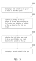
- Fig. 3 is a flow chart of the method for adaptively adjusting a hidden area mask of one embodiment of the present disclosure
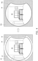
- Fig. 4 is a scenario applied with the proposed method of one embodiment of the present disclosure.
- the method of Fig. 3 could be performed by the HMD system of Fig. 2 , and the details of the steps of Fig. 3 will be discussed in accompanying with the elements of Fig. 2 and the scenario illustrated in Fig. 4 .
- the processor 24 controls the display 22 to display a first content 40 to an eye of a wearer of the HMD system 200.
- the first content 40 may be an image, a frame of a video, or a part of a scene presented to one of the eyes of the wearer, and the first content 40 may be masked by a first hidden area mask 42 (i.e., the illustrated black regions) during rendering to reduce GPU computation. That is, the unmasked region of the first content 40 is a first visible area 43 provided by the first hidden area mask 42.
- the considered eye of the wearer in the following discussions will be assumed to be the left eye of the wearer, but the present disclosure is not limited thereto.
- the processor 24 controls the image capturing device 21 to capture a plurality of first eye images of the eye while the display 22 displaying the first content 40 and obtains an eyesight of the eye based on the first eye images.
- the processor 24 may perform any known eye-tracking algorithms to track the considered eye (e.g., the left eye) of the wearer to obtain the eyesight of the considered eye.
- the processor 24 may obtain a plurality of gaze points of the left eye based on the first eye images during a predetermined period and use a range formed by the gaze points to define the eyesight of the left eye.
- the eyesight of the left eye of the wearer is assumed to be corresponding to a second visible area 44 smaller than the first visible area 43, and the second visible area 44 may be regarded as a maximum visible area of the left eye of the wearer, currently. That is, based on the retrieved eyesight of the left eye of the wearer, the unmasked regions of the content 40 between the second visible area 44 and the first hidden area mask 42 cannot be seen by the left eye of the wearer.
- step S330 the processor 24 adjusts the first hidden area mask 42 to be a second hidden area mask 42a based on the eyesight of the eye, and in step S340 the processor 24 controls the display 22 to display a second content 40a to the eye, wherein the second content 40a is masked by the second hidden area mask 42a.
- the second hidden area mask 42a corresponds to the second visible area 44. That is, the unmasked region of the second content 42a corresponds to the second visible area 44 provided by the second hidden area mask 42a.
- the proposed method enlarges the first hidden area mask 42 to be the second hidden area mask 42a to mask more portions of the displayed contents. Since the further masked portions of the displayed contents cannot be seen by the considered eye of the wearer in the first place, the loading of the GPU of the HMD system may be reduced for processing less image data without affecting the VR experience provided to the wearers.
- the second hidden area mask 42a is illustrated to be corresponding to the second visible area 44 (i.e., the maximum visible area of the left eye), in other embodiments, the second hidden area mask may be designed to have another aspect that provides a visible area slightly larger than the second visible area 44 but smaller than the first visible area 43. In this way, when the eyesight of the considered eye accidentally increases for some reasons, the visible area provided by the second hidden area mask may still fit the eyesight of the considered eye.
- the method of Fig. 3 may be recursively performed to repeatedly refine the size of the hidden area mask to better fit the maximum visible area of the considered eye of the wearer.
- the processor 24 may control the image capturing device 21 to capture a plurality of second eye images of the eye while the display 22 displaying the second content 42a. Next, the processor 24 may update the eyesight of the eye based on the second eye images and adjust the second hidden area mask 42a to be a third hidden area mask based on the updated eyesight of the eye. Afterwards, the processor 24 may control the display 22 to display a third content to the eye, wherein the third content is masked by the third hidden area mask.
- the method of Fig. 3 may be terminated, and the resulted hidden area mask may be used to mask the following contents until the HMD system 200 is turned off.
- the processor 24 may determine a similarity between the first hidden area mask 42 and the second hidden area mask 42a. If the similarity is higher than a threshold, the processor 24 may control the display 22 to display other contents to the eye based on the second hidden area mask 42a until the HMD system is turned off.
- the similarity between the first hidden area mask 42 and the second hidden area mask 42a may be obtained by: analysing the pixels commonly covered by the first hidden area mask 42 and the second hidden area mask 42a; and characterizing the percentage that the pixels take part in the second hidden area mask 42a as the similarity. If the similarity is higher than a threshold (e.g., 90%), it represents the second hidden area mask 42a may be stable enough to be applied to the following contents without sabotaging the VR experiences. Hence, the second hidden area mask 42a may be used to mask the following contents to be displayed by the display 22 until the HMD system 200 is turned off. When the HMD system 200 is turned on again, the method of Fig. 3 may be performed again to better fit the visible area of the current wearer.
- a threshold e.g. 90%
- the processor 24 may choose any two of consecutively obtained hidden area masks to calculate the similarity therebetween to determine whether the obtained hidden area masks have been stable enough.
- the processor 24 may determine whether the obtained hidden area masks are stable by analysing the similarities among the hidden area masks. If all of the similarities are higher than a threshold, the hidden area masks may be determined to be stable enough to be applied to the following contents until the HMD system 200 is turned off.
- the processor 24 may obtain a first similarity between the first hidden area mask 42 and the second hidden area mask 42a and a second similarity between the second hidden area mask 42a and the third hidden area mask. If the first and the second similarity are higher than a threshold (e.g., 95%), the hidden area masks may be determined to be stable enough, and the third hidden area mask may be applied to the following contents until the HMD system 200 is turned off.
- a threshold e.g., 95%
- the processor 24 may choose any number of consecutively obtained hidden area masks to calculate the similarities therebetween to determine whether the obtained hidden area masks have been stable enough. In this case, if all of the similarities are higher than the threshold, the hidden area masks may be determined to be stable enough to be applied to the following contents until the HMD system 200 is turned off.
- the present invention further provides a computer program product for executing foregoing method for adaptively adjusting a hidden area mask.
- the computer program product is composed of a plurality of program instructions (for example, a setting program instruction and a deployment program instruction) embodied therein. These program instructions can be loaded into an electronic device and executed by the same to execute the method for adaptively adjusting a hidden area mask and the functions of the electronic device described above.
- the present disclosure proposes a method for adaptively adjusting a hidden area mask, the HMD system using the same method, and a computer program produce, which may adaptively refine the hidden area mask to adjust the provided visible area based on the eyesight of the wearer of the HMD system. Since the display of the HMD system may display the subsequent contents with a smaller visible area after the hidden area mask is adaptively enlarged, the loading of the HMD system may be reduced, and hence the budget spent on the GPU may be reduced. From another perspective, the developer may have more budgets for 3D scene design and interactions.
Landscapes
- Engineering & Computer Science (AREA)
- Physics & Mathematics (AREA)
- Theoretical Computer Science (AREA)
- General Engineering & Computer Science (AREA)
- General Physics & Mathematics (AREA)
- Signal Processing (AREA)
- Multimedia (AREA)
- Human Computer Interaction (AREA)
- Geometry (AREA)
- Computer Graphics (AREA)
- Optics & Photonics (AREA)
- Controls And Circuits For Display Device (AREA)
- User Interface Of Digital Computer (AREA)
Claims (13)
- Ein am Kopf angebrachtes Anzeigesystem bzw. Head-Mounted-Display(HMD)-System (200), das aufweist:eine Bilderfassungsvorrichtung (21);eine Anzeige (22);einen nichtflüchtigen Speicher (23), der ein oder mehrere Programme speichert; undeinen Prozessor (24), der mit der Bilderfassungsvorrichtung (21), der Anzeige (22) und dem nichtflüchtigen Speicher (23) gekoppelt ist und konfiguriert ist, um das eine oder die mehreren Programme auszuführen, und zum:Steuern der Anzeige (22), um einen ersten Inhalt (40) einem Auge eines Trägers des Head-Mounted-Display-Systems (200) anzuzeigen, wobei der erste Inhalt (40) durch eine erste verborgener-Bereich-Maske (42) während der Darstellung maskiert ist;Steuern der Bilderfassungsvorrichtung (200) zum:Erfassen einer Vielzahl von ersten Augenbildern des Auges, während die Anzeige (22) den ersten Inhalt (40) anzeigt, undErhalten einer Vielzahl von Blickpunkten des Auges basierend auf den ersten Augenbildern während eines vorgegebenen Zeitraums;Verwenden eines durch die Blickpunkte gebildeten Bereichs, um einen Sichtbereich des Auges zu definieren;Anpassen der ersten verborgener-Bereich-Maske (42) als zweite verborgener-Bereich-Maske (42a) basierend auf dem definierten Sichtbereich des Auges des Trägers; undSteuern der Anzeige (22), um einen zweiten Inhalt (40a) dem Auge anzuzeigen, wobei der zweite Inhalt (40a) durch die zweite verborgener-Bereich-Maske (42a) maskiert ist.
- Das Head-Mounted-Display-System (200) gemäß Anspruch 1, wobei die erste verborgener-Bereich-Maske (42) einem ersten sichtbaren Bereich (43) entspricht, die zweite verborgener-Bereich-Maske (42a) einem zweiten sichtbaren Bereich (44) entspricht und der zweite sichtbare Bereich (44) kleiner ist als der erste sichtbare Bereich (43).
- Das Head-Mounted-Display-System (200) gemäß Anspruch 2, wobei der zweite sichtbare Bereich (44) dem Sichtbereich des Auges entspricht.
- Das Head-Mounted-Display-System (200) gemäß Anspruch 1, wobei der Prozessor (24) weiter konfiguriert ist zum:Steuern der Bilderfassungseinrichtung (21), um eine Vielzahl von zweiten Augenbildern des Auges zu erfassen, während die Anzeige (22) den zweiten Inhalt (40a) anzeigt;Aktualisieren des Sichtbereichs des Auges basierend auf den zweiten Augenbildern;Anpassen der zweiten verborgener-Bereich-Maske (42a) als dritte verborgener-Bereich-Maske basierend auf dem aktualisierten Sichtbereich des Auges; undSteuern der Anzeige (22), um einen dritten Inhalt dem Auge des Trägers anzuzeigen, wobei der dritte Inhalt durch die dritte verborgener-Bereich-Maske maskiert ist.
- Das Head-Mounted-Display-System (200) gemäß Anspruch 1, wobei der Prozessor (24) weiter konfiguriert ist zum:Bestimmen einer Ähnlichkeit zwischen der ersten verborgener-Bereich-Maske (42) und der zweiten verborgener-Bereich-Maske (42a); undwenn die Ähnlichkeit höher als ein Schwellenwert ist, Steuern der Anzeige (22), um andere Inhalte dem Auge anzuzeigen basierend auf der zweiten verborgener-Bereich-Maske (42a), bis das Head-Mounted-Display-System (200) ausgeschaltet wird.
- Das Head-Mounted-Display-System (200) gemäß Anspruch 5, wobei, wenn die Ähnlichkeit nicht höher als der Schwellenwert ist, der Prozessor (24) weiter konfiguriert ist zum:Steuern der Bilderfassungsvorrichtung (21), um eine Vielzahl von zweiten Augenbildern des Auges zu erfassen, während die Anzeige (22) den zweiten Inhalt anzeigt;Aktualisieren des Sichtbereichs des Auges basierend auf den zweiten Augenbildern;Anpassen der zweiten verborgener-Bereich-Maske als dritte verborgener-Bereich-Maske basierend auf dem aktualisierten Sichtbereich des Auges; undSteuern der Anzeige (22), um einen dritten Inhalt dem Auge anzuzeigen, wobei der dritte Inhalt durch die dritte verborgener-Bereich-Maske maskiert ist.
- Verfahren zum adaptiven Anpassen einer verborgener-Bereich-Maske, angepasst an ein Head-Mounted-Display-System (200), das aufweist:Anzeigen (S310) eines ersten Inhalts (40) einem Auge eines Trägers des Head-Mounted-Display-Systems (200), wobei der erste Inhalt (40) durch eine erste verborgener-Bereich-Maske (42) während der Darstellung maskiert ist;Erfassen (S320) einer Vielzahl von ersten Augenbildern des Auges, während der erste Inhalt (40) angezeigt wird;Erhalten (S320) einer Vielzahl von Blickpunkten des Auges basierend auf den ersten Augenbildern während eines vorgegebenen Zeitraums;Verwenden eines durch die Blickpunkte gebildeten Bereichs, um einen Sichtbereich des Auges zu definieren;Anpassen (S330) der ersten verborgener-Bereich-Maske (42) als zweite verborgener-Bereich-Maske (42a) basierend auf dem definierten Sehfeld des Auges des Trägers; undAnzeigen (S340) eines zweiten Inhalts (40a) dem Auge, wobei der zweite Inhalt (40a) durch die zweite verborgener-Bereich-Maske (42a) maskiert ist.
- Das Verfahren gemäß Anspruch 7, wobei die erste verborgener-Bereich-Maske (42) einem ersten sichtbaren Bereich (43) entspricht, die zweite verborgener-Bereich-Maske (42a) einem zweiten sichtbaren Bereich (44) entspricht und der zweite sichtbare Bereich (44) kleiner ist als der erste sichtbare Bereich (43).
- Das Verfahren gemäß Anspruch 8, wobei der zweite sichtbare Bereich (44) dem Sichtbereich des Auges entspricht.
- Das Verfahren gemäß Anspruch 7, das weiter aufweist:Erfassen einer Vielzahl von zweiten Augenbildern des Auges, während der zweite Inhalt (40a) angezeigt wird;Aktualisieren des Sichtbereichs des Auges basierend auf den zweiten Augenbildern;Anpassen der zweiten verborgener-Bereich-Maske (42a) als dritte verborgener-Bereich-Maske basierend auf dem aktualisierten Sichtbereich des Auges; undAnzeigen eines dritten Inhalts dem Auge, wobei der dritte Inhalt durch die dritte verborgener-Bereich-Maske maskiert ist.
- Das Verfahren gemäß Anspruch 7, das weiter aufweist:Bestimmen einer Ähnlichkeit zwischen der ersten verborgener-Bereich-Maske (42) und der zweiten verborgener-Bereich-Maske (42a); undwenn die Ähnlichkeit höher als ein Schwellenwert ist, Anzeigen anderer Inhalte dem Auge basierend auf der zweiten verborgener-Bereich-Maske (42a), bis das Head-Mounted-Display-System (200) ausgeschaltet wird.
- Das Verfahren gemäß Anspruch 11, wobei, wenn die Ähnlichkeit nicht höher als der Schwellenwert ist, es weiter aufweist:Erfassen einer Vielzahl von zweiten Augenbildern des Auges, während der zweite Inhalt (40a) angezeigt wird;Aktualisieren des Sichtbereichs des Auges basierend auf den zweiten Augenbildern;Anpassen der zweiten verborgener-Bereich-Maske (42a) als dritte verborgener-Bereich-Maske basierend auf dem aktualisierten Sichtbereich des Auges; undAnzeigen eines dritten Inhalts dem Auge, wobei der dritte Inhalt durch die dritte verborgener-Bereich-Maske maskiert ist.
- Computerprogrammprodukt zur Verwendung in Verbindung mit dem Head-Mounted-Display-System (200) gemäß einem der Ansprüche 1 bis 6, wobei das Computerprogrammprodukt ein computerlesbares Speichermedium und ein darin gespeichertes ausführbares Computerprogramm aufweist, wobei das ausführbare Computerprogramm Anweisungen zum Ausführen des Verfahrens gemäß einem der Ansprüche 7 bis 12 aufweist.
Applications Claiming Priority (2)
| Application Number | Priority Date | Filing Date | Title |
|---|---|---|---|
| US201762509198P | 2017-05-22 | 2017-05-22 | |
| US15/939,275 US10607399B2 (en) | 2017-05-22 | 2018-03-29 | Head-mounted display system, method for adaptively adjusting hidden area mask, and computer readable medium |
Publications (2)
| Publication Number | Publication Date |
|---|---|
| EP3407167A1 EP3407167A1 (de) | 2018-11-28 |
| EP3407167B1 true EP3407167B1 (de) | 2023-11-22 |
Family
ID=62217761
Family Applications (1)
| Application Number | Title | Priority Date | Filing Date |
|---|---|---|---|
| EP18172553.2A Active EP3407167B1 (de) | 2017-05-22 | 2018-05-16 | Kopfmontiertes anzeigesystem, verfahren zur adaptiven einstellung einer verborgenen bereichsmaske und computerprogrammprodukt |
Country Status (4)
| Country | Link |
|---|---|
| US (1) | US10607399B2 (de) |
| EP (1) | EP3407167B1 (de) |
| CN (1) | CN108931852B (de) |
| TW (1) | TWI653470B (de) |
Families Citing this family (4)
| Publication number | Priority date | Publication date | Assignee | Title |
|---|---|---|---|---|
| US10936057B2 (en) * | 2019-04-09 | 2021-03-02 | Samsung Electronics Co., Ltd. | System and method for natural three-dimensional calibration for robust eye tracking |
| CN111240466B (zh) * | 2019-09-02 | 2023-12-26 | 北京佳珥医学科技有限公司 | 辅助听力文字近眼显示适应性调节方法、控制设备和系统 |
| US11514875B1 (en) * | 2021-07-07 | 2022-11-29 | Htc Corporation | Method for mitigating dizziness, electronic device, and computer readable medium |
| US20260030793A1 (en) * | 2024-07-24 | 2026-01-29 | Samsung Electronics Co., Ltd. | Dynamic attentional region generation and rendering |
Family Cites Families (23)
| Publication number | Priority date | Publication date | Assignee | Title |
|---|---|---|---|---|
| US6466206B1 (en) | 1998-02-17 | 2002-10-15 | Sun Microsystems, Inc. | Graphics system with programmable real-time alpha key generation |
| JP2002157606A (ja) * | 2000-11-17 | 2002-05-31 | Canon Inc | 画像表示制御装置、複合現実感提示システム、画像表示制御方法、及び処理プログラムを提供する媒体 |
| US6943799B2 (en) * | 2002-03-29 | 2005-09-13 | The Boeing Company | Gaze directed visual system |
| EP1720058A4 (de) * | 2004-02-19 | 2010-03-24 | Scalar Corp | Bildanzeigeeinrichtung |
| JP4834606B2 (ja) * | 2007-05-16 | 2011-12-14 | キヤノン株式会社 | 画像処理方法及び画像処理装置 |
| CN103294397B (zh) * | 2008-04-30 | 2016-03-23 | 宏达国际电子股份有限公司 | 使用者界面显示区域的调整方法及装置 |
| CN101699862B (zh) * | 2009-11-16 | 2011-04-13 | 上海交通大学 | Ptz摄像机获取感兴趣区域高分辨率图像的方法 |
| TWI529574B (zh) * | 2010-05-28 | 2016-04-11 | 仁寶電腦工業股份有限公司 | 電子裝置與其操作方法 |
| US8831278B2 (en) | 2010-11-30 | 2014-09-09 | Eastman Kodak Company | Method of identifying motion sickness |
| JP6155643B2 (ja) * | 2013-01-07 | 2017-07-05 | セイコーエプソン株式会社 | 表示装置、および、表示装置の制御方法 |
| US9645395B2 (en) | 2013-03-15 | 2017-05-09 | Mark Bolas | Dynamic field of view throttling as a means of improving user experience in head mounted virtual environments |
| JP2014211720A (ja) * | 2013-04-17 | 2014-11-13 | 富士通株式会社 | 表示装置および表示制御プログラム |
| CN104704818B (zh) * | 2013-06-19 | 2018-08-31 | 松下知识产权经营株式会社 | 图像显示装置和图像显示方法 |
| US10365728B2 (en) * | 2015-06-11 | 2019-07-30 | Intel Corporation | Adaptive provision of content based on user response |
| KR20170033462A (ko) * | 2015-09-16 | 2017-03-27 | 삼성디스플레이 주식회사 | 전자 기기 및 헤드 마운트 디스플레이 장치의 영상 표시 방법 |
| EP3360029B1 (de) * | 2015-10-08 | 2019-11-13 | PCMS Holdings, Inc. | Verfahren und systeme zur automatischen kalibrierung für dynamische anzeigekonfigurationen |
| US11579686B2 (en) * | 2016-03-07 | 2023-02-14 | Apple Inc. | Method and device for carrying out eye gaze mapping |
| US10306315B2 (en) * | 2016-03-29 | 2019-05-28 | International Business Machines Corporation | Video streaming augmenting |
| EP3236306A1 (de) | 2016-04-20 | 2017-10-25 | Hexkraft GmbH | Verfahren zum rendering einer virtuellen 3d-realität und eine virtuelle-realität-ausrüstung zur implementierung des verfahrens |
| US20190143989A1 (en) * | 2016-05-11 | 2019-05-16 | Sony Corporation | Image processing device, image processing method, and movable body |
| CN106126143A (zh) * | 2016-06-29 | 2016-11-16 | 石惠卿 | 一种应用于头戴显示器的图像调整方法及头戴显示器 |
| CN106331681A (zh) * | 2016-08-22 | 2017-01-11 | 石惠卿 | 一种头戴显示器的图像显示方法 |
| US10643443B2 (en) * | 2016-12-30 | 2020-05-05 | Axis Ab | Alarm masking based on gaze in video management system |
-
2018
- 2018-03-29 US US15/939,275 patent/US10607399B2/en active Active
- 2018-05-04 TW TW107115333A patent/TWI653470B/zh active
- 2018-05-16 EP EP18172553.2A patent/EP3407167B1/de active Active
- 2018-05-18 CN CN201810478721.1A patent/CN108931852B/zh active Active
Also Published As
| Publication number | Publication date |
|---|---|
| TW201901240A (zh) | 2019-01-01 |
| TWI653470B (zh) | 2019-03-11 |
| US20180336719A1 (en) | 2018-11-22 |
| CN108931852A (zh) | 2018-12-04 |
| EP3407167A1 (de) | 2018-11-28 |
| US10607399B2 (en) | 2020-03-31 |
| CN108931852B (zh) | 2020-10-27 |
Similar Documents
| Publication | Publication Date | Title |
|---|---|---|
| US11461961B2 (en) | Spatially-resolved dynamic dimming for augmented reality device | |
| US20250014536A1 (en) | Image processing device and image processing method | |
| US11480804B2 (en) | Distributed foveated rendering based on user gaze | |
| US20250005855A1 (en) | Locations of media controls for media content and captions for media content in three-dimensional environments | |
| US10643307B2 (en) | Super-resolution based foveated rendering | |
| EP3302228B1 (de) | Verfahren und vorrichtung zur blickerkennung | |
| EP3195595B1 (de) | Technologien zur einstellung einer perspektive eines aufgenommenen bildes zur anzeige | |
| US9424767B2 (en) | Local rendering of text in image | |
| US20210074055A1 (en) | Intelligent Stylus Beam and Assisted Probabilistic Input to Element Mapping in 2D and 3D Graphical User Interfaces | |
| US20160323567A1 (en) | Virtual eyeglass set for viewing actual scene that corrects for different location of lenses than eyes | |
| CN112384843B (zh) | 动态面板掩膜 | |
| US10607399B2 (en) | Head-mounted display system, method for adaptively adjusting hidden area mask, and computer readable medium | |
| US12236560B2 (en) | Per-pixel filter | |
| JP2023099443A (ja) | Ar処理方法及び装置 | |
| US11543655B1 (en) | Rendering for multi-focus display systems | |
| US20170076697A1 (en) | Image Presentation Control Methods and Image Presentation Control Apparatuses | |
| US20200292825A1 (en) | Attention direction on optical passthrough displays | |
| US20250239030A1 (en) | Vertex pose adjustment with passthrough and time-warp transformations for video see-through (vst) extended reality (xr) | |
| US20220189433A1 (en) | Application programming interface for setting the prominence of user interface elements | |
| US20190204910A1 (en) | Saccadic breakthrough mitigation for near-eye display | |
| CN113269044A (zh) | 头戴式显示设备的显示控制方法、装置及头戴式显示设备 | |
| CN108027646B (zh) | 一种终端显示防抖方法及装置 | |
| US12366916B2 (en) | Method and system for determining a current gaze direction | |
| KR20170044319A (ko) | 헤드 마운트 디스플레이의 시야 확장 방법 | |
| CN112368668B (zh) | 用于混合现实头戴式耳机的便携式电子设备 |
Legal Events
| Date | Code | Title | Description |
|---|---|---|---|
| PUAI | Public reference made under article 153(3) epc to a published international application that has entered the european phase |
Free format text: ORIGINAL CODE: 0009012 |
|
| STAA | Information on the status of an ep patent application or granted ep patent |
Free format text: STATUS: EXAMINATION IS IN PROGRESS |
|
| 17P | Request for examination filed |
Effective date: 20180516 |
|
| AK | Designated contracting states |
Kind code of ref document: A1 Designated state(s): AL AT BE BG CH CY CZ DE DK EE ES FI FR GB GR HR HU IE IS IT LI LT LU LV MC MK MT NL NO PL PT RO RS SE SI SK SM TR |
|
| AX | Request for extension of the european patent |
Extension state: BA ME |
|
| RBV | Designated contracting states (corrected) |
Designated state(s): AL AT BE BG CH CY CZ DE DK EE ES FI FR GB GR HR HU IE IS IT LI LT LU LV MC MK MT NL NO PL PT RO RS SE SI SK SM TR |
|
| GRAP | Despatch of communication of intention to grant a patent |
Free format text: ORIGINAL CODE: EPIDOSNIGR1 |
|
| STAA | Information on the status of an ep patent application or granted ep patent |
Free format text: STATUS: GRANT OF PATENT IS INTENDED |
|
| INTG | Intention to grant announced |
Effective date: 20230620 |
|
| GRAS | Grant fee paid |
Free format text: ORIGINAL CODE: EPIDOSNIGR3 |
|
| GRAA | (expected) grant |
Free format text: ORIGINAL CODE: 0009210 |
|
| STAA | Information on the status of an ep patent application or granted ep patent |
Free format text: STATUS: THE PATENT HAS BEEN GRANTED |
|
| AK | Designated contracting states |
Kind code of ref document: B1 Designated state(s): AL AT BE BG CH CY CZ DE DK EE ES FI FR GB GR HR HU IE IS IT LI LT LU LV MC MK MT NL NO PL PT RO RS SE SI SK SM TR |
|
| REG | Reference to a national code |
Ref country code: GB Ref legal event code: FG4D |
|
| REG | Reference to a national code |
Ref country code: CH Ref legal event code: EP |
|
| REG | Reference to a national code |
Ref country code: DE Ref legal event code: R096 Ref document number: 602018061355 Country of ref document: DE |
|
| REG | Reference to a national code |
Ref country code: IE Ref legal event code: FG4D |
|
| REG | Reference to a national code |
Ref country code: NL Ref legal event code: FP |
|
| REG | Reference to a national code |
Ref country code: LT Ref legal event code: MG9D |
|
| PG25 | Lapsed in a contracting state [announced via postgrant information from national office to epo] |
Ref country code: GR Free format text: LAPSE BECAUSE OF FAILURE TO SUBMIT A TRANSLATION OF THE DESCRIPTION OR TO PAY THE FEE WITHIN THE PRESCRIBED TIME-LIMIT Effective date: 20240223 |
|
| PG25 | Lapsed in a contracting state [announced via postgrant information from national office to epo] |
Ref country code: IS Free format text: LAPSE BECAUSE OF FAILURE TO SUBMIT A TRANSLATION OF THE DESCRIPTION OR TO PAY THE FEE WITHIN THE PRESCRIBED TIME-LIMIT Effective date: 20240322 |
|
| PG25 | Lapsed in a contracting state [announced via postgrant information from national office to epo] |
Ref country code: LT Free format text: LAPSE BECAUSE OF FAILURE TO SUBMIT A TRANSLATION OF THE DESCRIPTION OR TO PAY THE FEE WITHIN THE PRESCRIBED TIME-LIMIT Effective date: 20231122 |
|
| REG | Reference to a national code |
Ref country code: AT Ref legal event code: MK05 Ref document number: 1634422 Country of ref document: AT Kind code of ref document: T Effective date: 20231122 |
|
| PG25 | Lapsed in a contracting state [announced via postgrant information from national office to epo] |
Ref country code: AT Free format text: LAPSE BECAUSE OF FAILURE TO SUBMIT A TRANSLATION OF THE DESCRIPTION OR TO PAY THE FEE WITHIN THE PRESCRIBED TIME-LIMIT Effective date: 20231122 |
|
| PG25 | Lapsed in a contracting state [announced via postgrant information from national office to epo] |
Ref country code: ES Free format text: LAPSE BECAUSE OF FAILURE TO SUBMIT A TRANSLATION OF THE DESCRIPTION OR TO PAY THE FEE WITHIN THE PRESCRIBED TIME-LIMIT Effective date: 20231122 |
|
| PG25 | Lapsed in a contracting state [announced via postgrant information from national office to epo] |
Ref country code: LT Free format text: LAPSE BECAUSE OF FAILURE TO SUBMIT A TRANSLATION OF THE DESCRIPTION OR TO PAY THE FEE WITHIN THE PRESCRIBED TIME-LIMIT Effective date: 20231122 Ref country code: IS Free format text: LAPSE BECAUSE OF FAILURE TO SUBMIT A TRANSLATION OF THE DESCRIPTION OR TO PAY THE FEE WITHIN THE PRESCRIBED TIME-LIMIT Effective date: 20240322 Ref country code: GR Free format text: LAPSE BECAUSE OF FAILURE TO SUBMIT A TRANSLATION OF THE DESCRIPTION OR TO PAY THE FEE WITHIN THE PRESCRIBED TIME-LIMIT Effective date: 20240223 Ref country code: ES Free format text: LAPSE BECAUSE OF FAILURE TO SUBMIT A TRANSLATION OF THE DESCRIPTION OR TO PAY THE FEE WITHIN THE PRESCRIBED TIME-LIMIT Effective date: 20231122 Ref country code: BG Free format text: LAPSE BECAUSE OF FAILURE TO SUBMIT A TRANSLATION OF THE DESCRIPTION OR TO PAY THE FEE WITHIN THE PRESCRIBED TIME-LIMIT Effective date: 20240222 Ref country code: AT Free format text: LAPSE BECAUSE OF FAILURE TO SUBMIT A TRANSLATION OF THE DESCRIPTION OR TO PAY THE FEE WITHIN THE PRESCRIBED TIME-LIMIT Effective date: 20231122 Ref country code: PT Free format text: LAPSE BECAUSE OF FAILURE TO SUBMIT A TRANSLATION OF THE DESCRIPTION OR TO PAY THE FEE WITHIN THE PRESCRIBED TIME-LIMIT Effective date: 20240322 |
|
| PG25 | Lapsed in a contracting state [announced via postgrant information from national office to epo] |
Ref country code: SE Free format text: LAPSE BECAUSE OF FAILURE TO SUBMIT A TRANSLATION OF THE DESCRIPTION OR TO PAY THE FEE WITHIN THE PRESCRIBED TIME-LIMIT Effective date: 20231122 Ref country code: RS Free format text: LAPSE BECAUSE OF FAILURE TO SUBMIT A TRANSLATION OF THE DESCRIPTION OR TO PAY THE FEE WITHIN THE PRESCRIBED TIME-LIMIT Effective date: 20231122 Ref country code: PL Free format text: LAPSE BECAUSE OF FAILURE TO SUBMIT A TRANSLATION OF THE DESCRIPTION OR TO PAY THE FEE WITHIN THE PRESCRIBED TIME-LIMIT Effective date: 20231122 Ref country code: NO Free format text: LAPSE BECAUSE OF FAILURE TO SUBMIT A TRANSLATION OF THE DESCRIPTION OR TO PAY THE FEE WITHIN THE PRESCRIBED TIME-LIMIT Effective date: 20240222 Ref country code: LV Free format text: LAPSE BECAUSE OF FAILURE TO SUBMIT A TRANSLATION OF THE DESCRIPTION OR TO PAY THE FEE WITHIN THE PRESCRIBED TIME-LIMIT Effective date: 20231122 Ref country code: HR Free format text: LAPSE BECAUSE OF FAILURE TO SUBMIT A TRANSLATION OF THE DESCRIPTION OR TO PAY THE FEE WITHIN THE PRESCRIBED TIME-LIMIT Effective date: 20231122 |
|
| PG25 | Lapsed in a contracting state [announced via postgrant information from national office to epo] |
Ref country code: DK Free format text: LAPSE BECAUSE OF FAILURE TO SUBMIT A TRANSLATION OF THE DESCRIPTION OR TO PAY THE FEE WITHIN THE PRESCRIBED TIME-LIMIT Effective date: 20231122 |
|
| PG25 | Lapsed in a contracting state [announced via postgrant information from national office to epo] |
Ref country code: CZ Free format text: LAPSE BECAUSE OF FAILURE TO SUBMIT A TRANSLATION OF THE DESCRIPTION OR TO PAY THE FEE WITHIN THE PRESCRIBED TIME-LIMIT Effective date: 20231122 |
|
| PG25 | Lapsed in a contracting state [announced via postgrant information from national office to epo] |
Ref country code: SK Free format text: LAPSE BECAUSE OF FAILURE TO SUBMIT A TRANSLATION OF THE DESCRIPTION OR TO PAY THE FEE WITHIN THE PRESCRIBED TIME-LIMIT Effective date: 20231122 |
|
| PG25 | Lapsed in a contracting state [announced via postgrant information from national office to epo] |
Ref country code: SM Free format text: LAPSE BECAUSE OF FAILURE TO SUBMIT A TRANSLATION OF THE DESCRIPTION OR TO PAY THE FEE WITHIN THE PRESCRIBED TIME-LIMIT Effective date: 20231122 Ref country code: SK Free format text: LAPSE BECAUSE OF FAILURE TO SUBMIT A TRANSLATION OF THE DESCRIPTION OR TO PAY THE FEE WITHIN THE PRESCRIBED TIME-LIMIT Effective date: 20231122 Ref country code: RO Free format text: LAPSE BECAUSE OF FAILURE TO SUBMIT A TRANSLATION OF THE DESCRIPTION OR TO PAY THE FEE WITHIN THE PRESCRIBED TIME-LIMIT Effective date: 20231122 Ref country code: IT Free format text: LAPSE BECAUSE OF FAILURE TO SUBMIT A TRANSLATION OF THE DESCRIPTION OR TO PAY THE FEE WITHIN THE PRESCRIBED TIME-LIMIT Effective date: 20231122 Ref country code: EE Free format text: LAPSE BECAUSE OF FAILURE TO SUBMIT A TRANSLATION OF THE DESCRIPTION OR TO PAY THE FEE WITHIN THE PRESCRIBED TIME-LIMIT Effective date: 20231122 Ref country code: DK Free format text: LAPSE BECAUSE OF FAILURE TO SUBMIT A TRANSLATION OF THE DESCRIPTION OR TO PAY THE FEE WITHIN THE PRESCRIBED TIME-LIMIT Effective date: 20231122 Ref country code: CZ Free format text: LAPSE BECAUSE OF FAILURE TO SUBMIT A TRANSLATION OF THE DESCRIPTION OR TO PAY THE FEE WITHIN THE PRESCRIBED TIME-LIMIT Effective date: 20231122 |
|
| REG | Reference to a national code |
Ref country code: DE Ref legal event code: R097 Ref document number: 602018061355 Country of ref document: DE |
|
| PLBE | No opposition filed within time limit |
Free format text: ORIGINAL CODE: 0009261 |
|
| STAA | Information on the status of an ep patent application or granted ep patent |
Free format text: STATUS: NO OPPOSITION FILED WITHIN TIME LIMIT |
|
| PG25 | Lapsed in a contracting state [announced via postgrant information from national office to epo] |
Ref country code: SI Free format text: LAPSE BECAUSE OF FAILURE TO SUBMIT A TRANSLATION OF THE DESCRIPTION OR TO PAY THE FEE WITHIN THE PRESCRIBED TIME-LIMIT Effective date: 20231122 |
|
| 26N | No opposition filed |
Effective date: 20240823 |
|
| PG25 | Lapsed in a contracting state [announced via postgrant information from national office to epo] |
Ref country code: SI Free format text: LAPSE BECAUSE OF FAILURE TO SUBMIT A TRANSLATION OF THE DESCRIPTION OR TO PAY THE FEE WITHIN THE PRESCRIBED TIME-LIMIT Effective date: 20231122 |
|
| REG | Reference to a national code |
Ref country code: CH Ref legal event code: PL |
|
| PG25 | Lapsed in a contracting state [announced via postgrant information from national office to epo] |
Ref country code: MC Free format text: LAPSE BECAUSE OF FAILURE TO SUBMIT A TRANSLATION OF THE DESCRIPTION OR TO PAY THE FEE WITHIN THE PRESCRIBED TIME-LIMIT Effective date: 20231122 |
|
| PG25 | Lapsed in a contracting state [announced via postgrant information from national office to epo] |
Ref country code: LU Free format text: LAPSE BECAUSE OF NON-PAYMENT OF DUE FEES Effective date: 20240516 |
|
| PG25 | Lapsed in a contracting state [announced via postgrant information from national office to epo] |
Ref country code: MC Free format text: LAPSE BECAUSE OF FAILURE TO SUBMIT A TRANSLATION OF THE DESCRIPTION OR TO PAY THE FEE WITHIN THE PRESCRIBED TIME-LIMIT Effective date: 20231122 Ref country code: LU Free format text: LAPSE BECAUSE OF NON-PAYMENT OF DUE FEES Effective date: 20240516 Ref country code: CH Free format text: LAPSE BECAUSE OF NON-PAYMENT OF DUE FEES Effective date: 20240531 |
|
| REG | Reference to a national code |
Ref country code: BE Ref legal event code: MM Effective date: 20240531 |
|
| PG25 | Lapsed in a contracting state [announced via postgrant information from national office to epo] |
Ref country code: IE Free format text: LAPSE BECAUSE OF NON-PAYMENT OF DUE FEES Effective date: 20240516 |
|
| PG25 | Lapsed in a contracting state [announced via postgrant information from national office to epo] |
Ref country code: BE Free format text: LAPSE BECAUSE OF NON-PAYMENT OF DUE FEES Effective date: 20240531 |
|
| PGFP | Annual fee paid to national office [announced via postgrant information from national office to epo] |
Ref country code: DE Payment date: 20250319 Year of fee payment: 8 |
|
| PG25 | Lapsed in a contracting state [announced via postgrant information from national office to epo] |
Ref country code: CY Free format text: LAPSE BECAUSE OF FAILURE TO SUBMIT A TRANSLATION OF THE DESCRIPTION OR TO PAY THE FEE WITHIN THE PRESCRIBED TIME-LIMIT; INVALID AB INITIO Effective date: 20180516 |
|
| PG25 | Lapsed in a contracting state [announced via postgrant information from national office to epo] |
Ref country code: HU Free format text: LAPSE BECAUSE OF FAILURE TO SUBMIT A TRANSLATION OF THE DESCRIPTION OR TO PAY THE FEE WITHIN THE PRESCRIBED TIME-LIMIT; INVALID AB INITIO Effective date: 20180516 |
|
| PG25 | Lapsed in a contracting state [announced via postgrant information from national office to epo] |
Ref country code: FI Free format text: LAPSE BECAUSE OF FAILURE TO SUBMIT A TRANSLATION OF THE DESCRIPTION OR TO PAY THE FEE WITHIN THE PRESCRIBED TIME-LIMIT Effective date: 20231122 |
|
| PGFP | Annual fee paid to national office [announced via postgrant information from national office to epo] |
Ref country code: GB Payment date: 20260312 Year of fee payment: 9 |
|
| PGFP | Annual fee paid to national office [announced via postgrant information from national office to epo] |
Ref country code: NL Payment date: 20260317 Year of fee payment: 9 |
|
| PGFP | Annual fee paid to national office [announced via postgrant information from national office to epo] |
Ref country code: FR Payment date: 20260309 Year of fee payment: 9 |