EP3406804A1 - Compact construction machinery - Google Patents
Compact construction machinery Download PDFInfo
- Publication number
- EP3406804A1 EP3406804A1 EP16886395.9A EP16886395A EP3406804A1 EP 3406804 A1 EP3406804 A1 EP 3406804A1 EP 16886395 A EP16886395 A EP 16886395A EP 3406804 A1 EP3406804 A1 EP 3406804A1
- Authority
- EP
- European Patent Office
- Prior art keywords
- heat exchanger
- cover
- engine
- revolving frame
- exchanger cover
- Prior art date
- Legal status (The legal status is an assumption and is not a legal conclusion. Google has not performed a legal analysis and makes no representation as to the accuracy of the status listed.)
- Granted
Links
Images






Classifications
-
- E—FIXED CONSTRUCTIONS
- E02—HYDRAULIC ENGINEERING; FOUNDATIONS; SOIL SHIFTING
- E02F—DREDGING; SOIL-SHIFTING
- E02F9/00—Component parts of dredgers or soil-shifting machines, not restricted to one of the kinds covered by groups E02F3/00 - E02F7/00
-
- B—PERFORMING OPERATIONS; TRANSPORTING
- B62—LAND VEHICLES FOR TRAVELLING OTHERWISE THAN ON RAILS
- B62D—MOTOR VEHICLES; TRAILERS
- B62D25/00—Superstructure or monocoque structure sub-units; Parts or details thereof not otherwise provided for
- B62D25/08—Front or rear portions
- B62D25/10—Bonnets or lids, e.g. for trucks, tractors, busses, work vehicles
-
- E—FIXED CONSTRUCTIONS
- E02—HYDRAULIC ENGINEERING; FOUNDATIONS; SOIL SHIFTING
- E02F—DREDGING; SOIL-SHIFTING
- E02F9/00—Component parts of dredgers or soil-shifting machines, not restricted to one of the kinds covered by groups E02F3/00 - E02F7/00
- E02F9/08—Superstructures; Supports for superstructures
- E02F9/0858—Arrangement of component parts installed on superstructures not otherwise provided for, e.g. electric components, fenders, air-conditioning units
- E02F9/0866—Engine compartment, e.g. heat exchangers, exhaust filters, cooling devices, silencers, mufflers, position of hydraulic pumps in the engine compartment
-
- B—PERFORMING OPERATIONS; TRANSPORTING
- B60—VEHICLES IN GENERAL
- B60K—ARRANGEMENT OR MOUNTING OF PROPULSION UNITS OR OF TRANSMISSIONS IN VEHICLES; ARRANGEMENT OR MOUNTING OF PLURAL DIVERSE PRIME-MOVERS IN VEHICLES; AUXILIARY DRIVES FOR VEHICLES; INSTRUMENTATION OR DASHBOARDS FOR VEHICLES; ARRANGEMENTS IN CONNECTION WITH COOLING, AIR INTAKE, GAS EXHAUST OR FUEL SUPPLY OF PROPULSION UNITS IN VEHICLES
- B60K11/00—Arrangement in connection with cooling of propulsion units
- B60K11/02—Arrangement in connection with cooling of propulsion units with liquid cooling
- B60K11/04—Arrangement or mounting of radiators, radiator shutters, or radiator blinds
-
- B—PERFORMING OPERATIONS; TRANSPORTING
- B62—LAND VEHICLES FOR TRAVELLING OTHERWISE THAN ON RAILS
- B62D—MOTOR VEHICLES; TRAILERS
- B62D25/00—Superstructure or monocoque structure sub-units; Parts or details thereof not otherwise provided for
- B62D25/08—Front or rear portions
- B62D25/10—Bonnets or lids, e.g. for trucks, tractors, busses, work vehicles
- B62D25/12—Parts or details thereof
-
- E—FIXED CONSTRUCTIONS
- E02—HYDRAULIC ENGINEERING; FOUNDATIONS; SOIL SHIFTING
- E02F—DREDGING; SOIL-SHIFTING
- E02F3/00—Dredgers; Soil-shifting machines
- E02F3/04—Dredgers; Soil-shifting machines mechanically-driven
- E02F3/28—Dredgers; Soil-shifting machines mechanically-driven with digging tools mounted on a dipper- or bucket-arm, i.e. there is either one arm or a pair of arms, e.g. dippers, buckets
- E02F3/30—Dredgers; Soil-shifting machines mechanically-driven with digging tools mounted on a dipper- or bucket-arm, i.e. there is either one arm or a pair of arms, e.g. dippers, buckets with a dipper-arm pivoted on a cantilever beam, i.e. boom
- E02F3/32—Dredgers; Soil-shifting machines mechanically-driven with digging tools mounted on a dipper- or bucket-arm, i.e. there is either one arm or a pair of arms, e.g. dippers, buckets with a dipper-arm pivoted on a cantilever beam, i.e. boom working downwardly and towards the machine, e.g. with backhoes
- E02F3/325—Backhoes of the miniature type
-
- E—FIXED CONSTRUCTIONS
- E02—HYDRAULIC ENGINEERING; FOUNDATIONS; SOIL SHIFTING
- E02F—DREDGING; SOIL-SHIFTING
- E02F9/00—Component parts of dredgers or soil-shifting machines, not restricted to one of the kinds covered by groups E02F3/00 - E02F7/00
- E02F9/08—Superstructures; Supports for superstructures
- E02F9/0808—Improving mounting or assembling, e.g. frame elements, disposition of all the components on the superstructures
-
- E—FIXED CONSTRUCTIONS
- E02—HYDRAULIC ENGINEERING; FOUNDATIONS; SOIL SHIFTING
- E02F—DREDGING; SOIL-SHIFTING
- E02F9/00—Component parts of dredgers or soil-shifting machines, not restricted to one of the kinds covered by groups E02F3/00 - E02F7/00
- E02F9/08—Superstructures; Supports for superstructures
- E02F9/0858—Arrangement of component parts installed on superstructures not otherwise provided for, e.g. electric components, fenders, air-conditioning units
- E02F9/0891—Lids or bonnets or doors or details thereof
-
- E—FIXED CONSTRUCTIONS
- E02—HYDRAULIC ENGINEERING; FOUNDATIONS; SOIL SHIFTING
- E02F—DREDGING; SOIL-SHIFTING
- E02F9/00—Component parts of dredgers or soil-shifting machines, not restricted to one of the kinds covered by groups E02F3/00 - E02F7/00
- E02F9/08—Superstructures; Supports for superstructures
- E02F9/10—Supports for movable superstructures mounted on travelling or walking gears or on other superstructures
- E02F9/12—Slewing or traversing gears
- E02F9/121—Turntables, i.e. structure rotatable about 360°
-
- E—FIXED CONSTRUCTIONS
- E02—HYDRAULIC ENGINEERING; FOUNDATIONS; SOIL SHIFTING
- E02F—DREDGING; SOIL-SHIFTING
- E02F9/00—Component parts of dredgers or soil-shifting machines, not restricted to one of the kinds covered by groups E02F3/00 - E02F7/00
- E02F9/16—Cabins, platforms, or the like, for drivers
-
- E—FIXED CONSTRUCTIONS
- E02—HYDRAULIC ENGINEERING; FOUNDATIONS; SOIL SHIFTING
- E02F—DREDGING; SOIL-SHIFTING
- E02F9/00—Component parts of dredgers or soil-shifting machines, not restricted to one of the kinds covered by groups E02F3/00 - E02F7/00
- E02F9/18—Counterweights
Definitions
- the present invention relates to small-sized construction machines such as hydraulic excavators, for example, and particularly, to a small-sized construction machine that is provided with a cover for covering an engine, a heat exchanger and the like to be capable of opening/closing.
- a hydraulic excavator that is a representative example of construction machines is provided with an automotive lower traveling structure, and an upper revolving structure that is rotatably mounted on the lower traveling structure.
- a working mechanism is tiltably provided in the front side of the upper revolving structure, and an excavating work of earth and sand and the like are performed by using this working mechanism.
- the upper revolving structure of the hydraulic excavator has a revolving frame that is formed as a support structure, and this revolving frame is provided thereon with mount equipment devices, such as an engine, a hydraulic pump and a heat exchanger and the like.
- the upper revolving structure is provided with an opening/closing type cover that covers various kinds of mount equipment devices to be capable of opening/closing. A worker can perform maintenance works such as inspection and maintenance to the engine and the heat exchanger by opening this opening/closing type cover.
- a side cover for covering the mount equipment device in a left-right direction has one end side in a front-rear direction that is usually supported by the revolving frame via a hinge mechanism and the other end side in the front-rear direction that acts as a free end. Accordingly, the side cover has a horizontal-opening structure of being rotatable in the front-rear direction (horizontal direction).
- This side cover is provided with a lock mechanism, which enables the side cover to be held (locked) in a closed state (refer to Patent Document 1).
- Patent Document 1 Japanese Patent Laid-Open No. 2002-321651 A
- the aforementioned side cover having the horizontal-opening structure cannot hold the closed state thereof in a case where a failure of the lock mechanism or the like occurs, for example.
- the side cover opens inadvertently by a revolving movement of the upper revolving structure and therefore, the side cover collides with obstacles in the circumference to be damaged.
- a small-sized hydraulic excavator called a mini-excavator is loaded on a small-sized truck to be transported to a working site and is used for a demolition work of the inside of a building, an excavating work in a narrow area such as an urban area, and the like. Therefore, a total weight of the small-sized hydraulic excavator is suppressed to approximately 0.7 to 8 tons, for example. Accordingly, in such a small-sized hydraulic excavator, the upper revolving structure is sized to be small and a space for arranging the mount equipment device on the revolving frame is small.
- an operating space at the time of operating the lock mechanism provided in the cover that covers the mount equipment device to be capable of opening/closing is narrow, leading to a problem that workability of the maintenance work is worsened.
- the present invention is made in view of the aforementioned problems in the conventional art, and an object of the present invention is to provide a small-sized construction machine that can hold a cover for covering a mount equipment device in a closed state.
- the present invention is characterized in that: the heat exchanger cover is formed of a horizontal-opening structure of being rotatable to the revolving frame with a front end in a front-rear direction as a fulcrum and a rear end in the front-rear direction as a free end; and a lock mechanism is provided on a rear end side of the heat exchanger cover to hold the heat exchanger cover in a closed state, wherein in a state where both the heat exchanger cover and the engine cover are closed, the engine cover covers the rear end of the heat exchanger cover and the lock mechanism from backward.
- the present invention in a state where both the heat exchanger cover and the engine cover are closed, it is possible to hold the rear end of the heat exchanger cover of the horizontal-opening structure with the engine cover. Accordingly, even in a case where the heat exchanger cover is not locked in the closed state, for example, because of a failure of the lock mechanism or the like, the rear end of the heat exchanger cover is held by the engine cover, thus making it possible to suppress the heat exchanger cover from rotating in the front-rear direction (horizontal direction) by the revolving movement of the upper revolving structure. As a result, it is possible to suppress the heat exchanger cover from opening inadvertently at the revolving movement time to interfere with surrounding obstacles.
- a small-sized hydraulic excavator 1 is provided with an automotive lower traveling structure 2 of a crawler type, and an upper revolving structure 4 that is rotatably mounted on the lower traveling structure 2 through a revolving device 3.
- the small-sized hydraulic excavator 1 is loaded on a small-sized truck to be transported to a working site and is used for a demolition work of the inside of a building, an excavating work in a narrow area of an urban area or the like. Therefore, a total weight of the small-sized hydraulic excavator 1 is suppressed to approximately 0.7 to 8 tons, for example.
- the upper revolving structure 4 includes a revolving frame 6, a counterweight 7, an engine 8, a heat exchanger 10, a support member 14, a cab 15 and an exterior cover 19, which will be described later.
- the small-sized hydraulic excavator 1 is applied to a narrow working site such as the inside of a building or an urban area, for example, the upper revolving structure 4 is formed to be small. Therefore, in the hydraulic excavator 1, a space for arranging various kinds of mounted equipment on the revolving frame 6 is narrow, and a rear position of the cab 15 is arranged on the upper side of the engine 8 and the heat exchanger 10.
- the revolving frame 6 is rotatably provided on the lower traveling structure 2 through the revolving device 3.
- the revolving frame 6 is formed as a support structural body and acts as a base of the upper revolving structure 4.
- the revolving frame 6 includes a bottom plate 6A formed in a rectangular shape to extend in a front-rear direction by using a thick steel plate or the like, and a left vertical plate 6B and a right vertical plate 6C arranged vertically to extend in the front-rear direction on the bottom plate 6A.
- a support bracket 6D is provided in a front end part of each of the left vertical plate 6B and the right vertical plate 6C.
- the support bracket 6D swingably supports the swing post 5A provided in the base end of the working mechanism 5 in the left-right direction.
- a left rear bracket 6E and a right rear bracket 6F are provided in rear end parts of the left vertical plate 6B and the right vertical plate 6C.
- the counterweight 7 to be described later is mounted in the left rear bracket 6E and the right rear bracket 6F, and a left rear leg part 14C and a right rear leg part 14D of the support member 14 to be described later are mounted therein.
- a horizontal plate 6G is vertically arranged in the intermediate part of the bottom plate 6A in the front-rear direction to extend in the left-right direction across the intermediate part of the left vertical plate 6B in the front-rear direction.
- the horizontal plate 6G extends to a left end edge part of the bottom plate 6A over the left vertical plate 6B from the right vertical plate 6C.
- a left front leg part 14A of the support member 14 is mounted in a left end part of the horizontal plate 6G.
- a support-member support bracket 6H erecting upward from the bottom plate 6A is mounted in a right end part of the bottom plate 6A positioned on an extension line of the horizontal plate 6G.
- a right front leg part 14B of the support member 14 is mounted in the support-member support bracket 6H.
- a heat exchanger support base 6J is provided in the vicinity of a part of the bottom plate 6A in which the right vertical plate 6C and the right rear bracket 6F cross to extend along the right vertical plate 6C in the front-rear direction (refer to Fig. 7 ) .
- the heat exchanger 10 to be described later is mounted on the heat exchanger support base 6J.
- a left cover bracket 6K is provided in a left end part of the bottom plate 6A positioned ahead of the horizontal plate 6G to extend upward.
- a left front cover 20 to be described later is mounted in the left cover bracket 6K.
- a right front cover bracket 6L is provided in a right front part of the bottom plate 6A to extend upward.
- a right front cover 21 to be described later is mounted in the right front cover bracket 6L.
- the counterweight 7 is mounted on the rear end of the revolving frame 6.
- the counterweight 7 acts as a weight balance to the working mechanism 5, and is formed as a heavy load in a convex curved shape.
- the counterweight 7 is mounted in the left rear bracket 6E and the right rear bracket 6F in the revolving frame 6 respectively by using bolts 7A.
- a left corner part and a right corner part of the counterweight 7 respectively are chamfered in an arc shape not to become angular. Accordingly, the counterweight 7 can avoid interference with the surrounding obstacles at the revolving movement of the upper revolving structure 4.
- the engine 8 is mounted closer to the rear side of the horizontal plate 6G of the revolving frame 6.
- the engine 8 is arranged on the revolving frame 6 in a horizontal state where a crank shaft (not shown) extends in the left-right direction.
- a hydraulic pump (not shown) is provided in the left side to the engine 8. The hydraulic pump is driven by the engine 8 to deliver pressurized oil toward various kinds of hydraulic actuators mounted on the hydraulic excavator 1.
- a cooling fan 9 is provided in the right side as one side in the left-right direction to the engine 8.
- the cooling fan 9 rotates adopting the engine 8 as a power source to suck in outside air as cooling air, and supplies the cooling air to the heat exchanger 10 to be described later.
- the heat exchanger 10 is positioned upstream side of the cooling fan 9 in a flowing direction of the cooling air and is provided on the revolving frame 6.
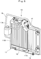
- the heat exchanger 10, as shown in Fig. 6 includes a frame body 11, a radiator 12 and an oil cooler 13, which will be described later.
- the heat exchanger 10 is mounted on the heat exchanger support base 6J of the revolving frame 6 and extends along the right vertical plate 6C in the front-rear direction.
- the frame body 11 configures an outer shell of the heat exchanger 10, and supports the radiator 12, the oil cooler 13 and the like integrally.
- the frame body 11 is formed in a rectangular frame shape as a whole by performing bending work to a steel plate member, for example.
- the frame body 11 includes a bottom plate 11A extending in the front-rear direction, and a rear plate 11B arranged in the rear side of the bottom plate 11A and extending in the upper-lower direction.
- the rear plate 11B configures the rear end of the heat exchanger 10.
- the heat exchanger 10 is arranged vertically on the revolving frame 6 by mounting the bottom plate 11A of the frame body 11 on the heat exchanger support base 6J of the revolving frame 6 using a plurality of bolts.
- the bottom plate 11A of the frame body 11 is provided with the radiator 12 and the oil cooler 13 mounted to line up in parallel to a flow of cooling air. That is, the radiator 12 and the oil cooler 13 are mounted on the frame body 11 to line up in the front-rear direction. In this state, a partition member 17 to be described later is mounted in the frame body 11 to extend from the surroundings of the radiator 12 and the oil cooler 13.
- the radiator 12 is mounted to the frame body 11 in a position closer to the rear plate 11B.
- the radiator 12 faces the cooling fan 9 in the left-right direction.
- the radiator 12 is arranged to extend in the front-rear direction such that the flowing direction of the cooling air becomes the left-right direction.
- the radiator 12 is connected to a water jacket (not shown) of the engine 8.
- the radiator 12 is to cool engine cooling water, a temperature of which has increased by cooling the engine 8, by cooling air.
- the oil cooler 13 is mounted to the frame body 11 to be adjacent to the front side of the radiator 12.
- the oil cooler 13 faces the cooling fan 9 in the left-right direction.
- the oil cooler 13, as similar to the radiator 12, is arranged to extend in the front-rear direction such that the flowing direction of the cooling air becomes the left-right direction.
- the oil cooler 13 cools the hydraulic oil, which is returned from various kinds of hydraulic actuators mounted on the hydraulic excavator 1 and a temperature of which has increased and, by cooling air, and the cooled hydraulic oil is circulated to an hydraulic oil tank.
- the support member 14 is arranged closer to the rear side than the horizontal plate 6G of the revolving frame 6 and is mounted to the revolving frame 6 to bridge over the engine 8 and the heat exchanger 10.
- the support member 14 supports the rear side of the cab 15 to be described later and is configured for a base of an operator's seat (any of them is not shown) arranged in the inside of the cab 15 to be mounted thereon.
- the support member 14 includes the left front leg part 14A, the right front leg part 14B, the left rear leg part 14C, the right rear leg part 14D and a support base 14E mounted on the upper end of each of the leg parts 14A, 14B, 14C, 14D.
- a lower end of the left front leg part 14A is bolted to a left end part of the horizontal plate 6G configuring part of the revolving frame 6. An upper end of the left front leg part 14A is inclined obliquely toward the backward side.
- a lower end of the right front leg part 14B is bolted to the support-member support bracket 6H of the revolving frame 6. An upper end of the right front leg part 14B is inclined obliquely toward the backward side.
- a lower end of the left rear leg part 14C is bolted to the left rear bracket 6E of the revolving frame 6. An upper end of the left rear leg part 14C extends upward.
- a lower end of the right rear leg part 14D is bolted to the right rear bracket 6F of the revolving frame 6.
- An upper end of the right rear leg part 14D extends upward.
- a fastening tool 31 to be described later is provided in the intermediate part of the right rear leg part 14D in the upper-lower direction to project toward the backward side.
- the support base 14E is fixed to an upper end of each of the left front leg part 14A, the right front leg part 14B, the left rear leg part 14C and the right rear leg part 14D.
- the support base 14E has a length dimension substantially equal to a width dimension of the revolving frame 6 in the left-right direction, and connects the upper ends of the leg parts 14A, 14B, 14C, 14D with each other.
- the support base 14E extends in the left-right direction above the engine 8 and the heat exchanger 10, and supports the rear side of the cab 15 on the upper side to the engine 8 and the heat exchanger 10.
- the cab 15 is mounted on the revolving frame 6 in a state of covering the revolving frame 6 over a substantially entire region from above to define an operator's room.
- the cab 15 has a length dimension in the front-rear direction having 70% to 90% or more of the upper revolving structure 4 in the front-rear direction, for example. Accordingly, occupant comfort in the inside of the cab 15 is enhanced in the small-sized hydraulic excavator 1. As shown in Fig. 1 to Fig.
- the cab 15 is formed in a boxy shape to be surrounded by a front surface part 15A, a rear surface part 15B facing the front surface part 15A in the front-rear direction, a left side surface part 15C positioned in the left side between the front surface part 15A and the rear surface part 15B, a right side surface part 15D facing the left side surface part 15C and an upper surface part 15E for closing an upper end of each of the front surface part 15A, the rear surface part 15B, the left side surface part 15C and the right side surface part 15D.
- a recessed part 15F recessed toward the upper side and the front side is formed in a rear lower side of the cab 15, and the cab 15 is formed in a stepped boxy shape as a whole.
- the recessed part 15F in the rear side of the cab 15 is supported by the support base 14E of the support member 14 and covers the engine 8 and the heat exchanger 10 from above. Accordingly, the cab 15 is mounted on the revolving frame 6 in a state of covering the revolving frame 6 over a substantially entire region from above, thus making it possible to largely secure a residence space in the inside of the cab 15. On the other hand, the space formed between the revolving frame 6 and the cab 15 becomes narrow.
- an equipment device accommodating room 16 is formed between the bottom plate 6A of the revolving frame 6 and the recessed part 15F of the cab 15 to be covered with the exterior cover 19 to be described later.
- the equipment device accommodating room 16 is partitioned into an engine room 16A for accommodating the engine 8 and the like and a heat exchanger room 16B for accommodating the heat exchanger 10 and the like across the partition member 17 to be described later.
- the engine room 16A is covered with an engine cover 23 to be described later to be capable of opening/closing.
- the heat exchanger room 16B is covered with a heat exchanger cover 28 to be described later to be capable of opening/closing.
- the partition member 17 is provided integrally with the frame body 11 to extend from the surroundings of the radiator 12 and the oil cooler 13 configuring part of the heat exchanger 10 (refer to Fig. 6 ). That is, the partition member 17 forms an outer peripheral part of the frame body 11.
- the partition member 17 seals the engine room 16A in a state where the engine cover 23 is closed, and seals the heat exchanger room 16B in a state where the heat exchanger cover 28 is closed. Accordingly, the partition member 17 defines the equipment device accommodating room 16 into the engine room 16A and the heat exchanger room 16B.
- a seal material 18 formed of an elastic material such as rubber and the like is provided on an outer peripheral edge of the partition member 17. The seal material 18 is to seal a clearance formed between the outer peripheral edge of the partition member 17 and an inner peripheral surface of the engine cover 23 or the like when the engine cover 23 is closed (refer to Fig. 11 ).
- the cooling air sucked in the heat exchanger room 16B by the cooling fan 9 passes through the heat exchanger 10, and after that, is supplied to the engine room 16A.
- the partition member 17 can block penetration of the cooling air into the heat exchanger room 16B from the engine room 16A to prevent the cooling air a temperature of which has increased in the engine room 16A from penetrating into the heat exchanger room 16B.
- a low-temperature cooling air is supplied into the heat exchanger room 16B from an exterior.
- the exterior cover 19 is arranged on the circumference of the revolving frame 6 between the counterweight 7 and the cab 15.
- the exterior cover 19 covers mount equipment devices such as the engine 8, the cooling fan 9 and the heat exchanger 10 and the like, which are mounted on the revolving frame 6.
- the exterior cover 19 includes the left front cover 20, a right front cover 21, a left rear cover 22, the engine cover 23 and the heat exchanger cover 28 to be described later.
- the left front cover 20 has a lower side that is arranged between the left end part and the front end part of the bottom plate 6A configuring part of the revolving frame 6 and an upper side that is arranged between the left side surface part 15C and the front surface part 15A of the cab 15.
- the left front cover 20 is formed in an L-letter shape extending along the left end part and the front end part of the bottom plate 6A.
- the left front cover 20 is mounted to the left cover bracket 6K of the revolving frame 6 and the like.
- the right front cover 21 has a lower side that is arranged between the right end part and the front end part of the bottom plate 6A configuring part of the revolving frame 6 and an upper side that is arranged between the right side surface part 15D and the front surface part 15A of the cab 15.
- the right front cover 21 is formed in an L-letter shape extending along the right end part and the front end part of the bottom plate 6A.
- the right front cover 21 is mounted to the right front cover bracket 6L of the revolving frame 6 and the like.
- the left rear cover 22 has a lower side that is arranged between the left end part of the bottom plate 6A configuring part of the revolving frame 6 and the counterweight 7 and an upper side that is arranged in a position corresponding to the recessed part 15F of the left side surface part 15C of the cab 15.
- the left rear cover 22 is formed in an L-letter shape bending along the left end part and the rear end part of the bottom plate 6A.
- the left front cover 22 is mounted fixedly to a bracket (not shown) provided in the support member 14, for example.
- the left rear cover 22 covers the engine 8, a hydraulic pump (not shown) and the like accommodated in the engine room 16A from the left side.
- a left corner part of the left rear cover 22 is chamfered in an arc shape not to become angular. Accordingly, the left corner part of the left rear cover 22 can avoid interference with the surrounding obstacles at the revolving movement of the upper revolving structure 4.
- the engine cover 23 is arranged between a part of the rear surface part 15B of the cab 15 corresponding to the recessed part 15F and the counterweight 7 to be capable of opening/closing in the upper-lower direction.
- the engine cover 23 is arranged between the left rear cover 22 and the heat exchanger cover 28, and is bent in an arc shape along the rear surface of the counterweight 7.
- the engine cover 23 covers the engine 8 accommodated in the engine room 16A, the heat exchanger 10 accommodated in the heat exchanger room 16B, and the like from the rear side.
- the engine cover 23 is mounted to the support member 14 through a link mechanism 23A.
- the engine cover 23 moves in the upper-lower direction between a closed position shown in Fig. 2 and an opened position shown in Fig. 3 .
- the engine cover 23 is provided with an engine cover lock mechanism 24 that holds the engine cover 23 in the closed state (closed position).
- the engine cover lock mechanism 24 has a paw member 24A that projects to the forward side from an inner side surface of the engine cover 23.
- the paw member 24A is engaged to a reverse U-letter-shaped hook 25 provided in the counterweight 7 when the engine cover 23 is closed.
- a lock release operation tool 26 is provided on an outer side surface of the engine cover 23. The lock release operation tool 26 releases the engaging state of the paw member 24A to the hook 25.
- the lock release operation tool 26 is operated from the outside of the engine cover 23 in the closed position by using a key (not shown) or the like. Accordingly, the paw member 24A of the engine cover lock mechanism 24 is disengaged from the hook 25, making it possible to open the engine cover 23 upward by the link mechanism 23A.
- a seal member 27 formed of an elastic material such as rubber and the like is provided on an outer peripheral edge of the engine cover 23.
- the seal member 27 seals a clearance to the heat exchanger cover 28 when the engine cover 23 is closed. Accordingly, rainwater, dusts and the like can be suppressed from entering the equipment device accommodating room 16 through the outer peripheral edge of the engine cover 23.
- the heat exchanger cover 28 has a lower side that is arranged between the right end part of the bottom plate 6A configuring part of the revolving frame 6 and the counterweight 7 and an upper side that is arranged in a part corresponding to the recessed part 15F of the right side surface part 15D of the cab 15 to be capable of opening/closing in the front-rear direction.
- the heat exchanger cover 28 is formed in an L-letter shape along the right end part and the rear end part of the bottom plate 6A.
- the heat exchanger cover 28 covers the heat exchanger 10 accommodated in the heat exchanger room 16B, and the like from the right side.
- a right corner part of the heat exchanger cover 28 is chamfered in an arc shape not to become angular. Accordingly, the right corner part of the heat exchanger cover 28 can avoid interference with the surrounding obstacles at the revolving movement of the upper revolving structure 4.
- the heat exchanger cover 28 includes a right surface plate 28A and a rear surface plate 28B bent in the left side toward the engine cover 23 from the rear end side of the right surface plate 28A.
- the right surface plate 28A extends in the front-rear direction in a state of facing the radiator 12 in the heat exchanger 10 and the like.
- the rear surface plate 28B faces the frame body 11 (rear plate 11B) in the heat exchanger 10 in the front-rear direction.
- a front end 28C of the heat exchanger cover 28 (right surface plate 28A) in the front-rear direction is rotatably mounted in the right front leg part 14B of the support member 14 through a hinge member 29.
- a rear end 28D of the heat exchanger cover 28 becomes a free end.
- the rear end 28D is rotatable in the front-rear direction (horizontal direction) on a basis of the front end 28C supported by the hinge member 29. Accordingly, the heat exchanger cover 28 is configured to open/close in the horizontal direction between the closed position shown in Fig. 2 and Fig. 11 and the opened position shown in Fig. 3 .
- a plurality of air flowing openings 28E are formed in the right surface plate 28A of the heat exchanger cover 28 to line up in the upper-lower direction. At rotation of the cooling fan 9, outside air is sucked in the inside of the heat exchanger room 16B through each of the air flowing openings 28E.
- a plate-shaped mounting seat 28G bent in an L-letter shape is fixed to an inner surface 28F positioned in the inside of a narrow space 30, which will be described later, of the rear surface plate 28B.
- a heat exchanger cover lock mechanism 32 to be described later is mounted to the mounting seat 28G.
- the narrow space 30 surrounded by the engine cover 23, the heat exchanger cover 28 and the partition member 17 is formed closer to the rear side than the heat exchanger 10.
- the narrow space 30 usually acts as a dead space.
- the right rear leg part 14D of the support member 14 is arranged in the inside of the narrow space 30, as well as the fastening tool 31 to be described later and the heat exchanger cover lock mechanism 32 are provided therein.
- the narrow space 30 is formed as a space surrounded by an extension part 23C of the engine cover 23, an extension part 28H of the heat exchanger cover 28 and an extension part 17A of the partition member 17.
- the extension part 23C of the engine cover 23 is a part extended to the heat exchanger room 16B-side from the partition member 17.
- the extension part 28H of the heat exchanger cover 28 is a part extended closer to the rear side than the rear plate 11B (rear end of the heat exchanger 10) of the frame body 11 configuring part of the heat exchanger 10.
- the extension part 17A of the partition member 17 is a part extended closer to the rear side than the rear plate 11B of the heat exchanger 10.
- the fastening tool 31 is provided in the right rear leg part 14D of the support member 14. In this case, the fastening tool 31 is arranged in a part closer to the upper side than the right rear bracket 6F of the revolving frame 6. The fastening tool 31 is engaged to an engaging groove 37 of a latch 36 to be described later. As shown in Fig. 11 , the fastening tool 31 is formed of a columnar shaft body on which a male screw 31A is formed, and is mounted to be removable (replaceable) to the right rear leg part 14D by using bolts 31B. The fastening tool 31 extends backward from the rear surface of the right rear leg part 14D and a tip end of the fastening tool 31 projects into the narrow space 30.
- the heat exchanger cover lock mechanism 32 is provided in the rear end side of the heat exchanger cover 28.
- the heat exchanger cover lock mechanism 32 holds (locks) the heat exchanger cover 28 in the closed state.
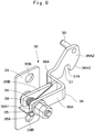
- the heat exchanger cover lock mechanism 32 includes a mounting base 33, the latch 36, the engaging groove 37, a spring member 38 and a lock release pin 39, which will be described later.
- the mounting base 33 is formed of a rectangular flat plate extending in the upper-lower direction.
- the mounting base 33 is fixed to the mounting seat 28G provided on the inner surface 28F of the heat exchanger cover 28 by using bolts 33A.
- the mounting base 33 is arranged in the inside of the narrow space 30.
- a support shaft 34 is fixed in the intermediate part of the mounting base 33 in the upper-lower direction.
- the support shaft 34 projects forward (to the heat exchanger 10-side) from the mounting base 33.
- a spring receiving plate 35 is fixed to the mounting base 33 on the lower side of the support shaft 34.
- a notched portion 35A is provided in the spring receiving plate 35, and one end side of the spring member 38 to be described later is hooked in the notched portion 35A.
- the latch 36 is rotatably supported on the support shaft 34.
- the latch 36 rotates in the inside of the narrow space 30 in the upper-lower direction to cause the engaging groove 37 to be engaged to and disengaged from the fastening tool 31.
- the latch 36 includes a bending plate 36A formed of a plate body bent in a crank shape, and a rectangular supplementary plate 36B fixed on the bending plate 36A.
- the supplementary plate 36B faces a base end part 36A1 of the bending plate 36A by an interval in the front-rear direction.
- the base end part 36A1 of the bending plate 36A and the supplementary plate 36B are rotatably inserted in the support shaft 34 in the upper-lower direction.
- An arc-shaped cam surface 36A3 is provided in a position corresponding to the fastening tool 31 on an outer peripheral edge of a tip end part 36A2 of the bending plate 36A.
- the cam surface 36A3 abuts on the fastening tool 31 when the heat exchanger cover 28 closes from the opened state.
- the tip end part 36A2 of the latch 36 rotates upward at the center of the support shaft 34 along the shape of the cam surface 36A3 to guide an open end 37A of the engaging groove 37 to be described later toward the fastening tool 31.
- the engaging groove 37 is provided in the tip end part 36A2 of the bending plate 36A configuring part of the latch 36.
- the engaging groove 37 is engaged to the fastening tool 31.
- the engaging groove 37 is formed by notching a lower end edge of the tip end part 36A2 of the bending plate 36A upward.
- a lower end of the engaging groove 37 is formed as the open end 37A opened downward in the proximate part of the cam surface 36A3 of the bending plate 36A. Accordingly, when the heat exchanger cover 28 closes from the opened state, the tip end part 36A2 of the latch 36 gradually rotates upward at the center of the support shaft 34 along the shape of the cam surface 36A3.
- the tip end part 36A2 of the latch 36 rotates downward at the center of the support shaft 34 due to engagement of the open end 37A of the engaging groove 37 to the fastening tool 31.
- the engaging groove 37 provided in the tip end part 36A2 of the latch 36 is automatically engaged to the fastening tool 31 fixed to the right rear leg part 14D of the support member 14.
- the latch 36 can hold (lock) the heat exchanger cover 28 in the closed state.
- bolt insertion holes 33B (refer to Fig. 9 ) formed in the mounting base 33 each are set to have a hole diameter for forming an appropriate clearance to the bolt 33A.
- the spring member 38 is provided to wind around the support shaft 34 between the base end part 36A1 of the bending plate 36A and the supplementary plate 36B that configure part of the latch 36.
- One end 38A of the spring member 38 is hooked in the supplementary plate 36B, and the other end (not shown) of the spring member 38 is hooked in the spring receiving plate 35.
- the spring member 38 urges the tip end part 36A2 of the latch 36 (bending plate 36A) in a direction of rotating downward at the center of the support shaft 34.
- the lock release pin 39 is positioned in the vicinity of the engaging groove 37 to be provided in the tip end part 36A2 of the bending plate 36A configuring part of the latch 36.
- the lock release pin 39 projects backward from the tip end part 36A2 of the bending plate 36A.
- the lock release pin 39 is operated upward to disengage the engaging groove 37 of the latch 36 from the fastening tool 31 against an urging force of the spring member 38.
- the hydraulic excavator 1 has the configuration as described above, and next, an operation thereof will be explained.
- the small-sized hydraulic excavator 1 a total weight of which is approximately 0.7 to 8 tons is transported to a working site in a state of being loaded on a loading platform of the small-sized truck.
- an operator gets in the inside of the cab 15 to operate the lever/pedal for travel and the operating lever for work (any of them is not shown) arranged in the inside of the cab 15. Accordingly, the hydraulic excavator 1 self-travels to the desired working site, and after that, performs a demolition work of the inside of a building, a side ditch digging work in a narrow urban area and the like and an excavating work of earth and sand.
- the hydraulic excavator 1 has a length dimension of the cab 15 in the front-rear direction that is for example, 70% to 90% or more of a length dimension of the upper revolving structure 4 in the front-rear direction. Therfore, the hydraulic excavator 1 can enhance occupant comfort in the inside of the cab 15.
- the left corner part and the right corner part of the counterweight 7 are chamfered in an arc shape
- the left corner part of the left rear cover 22 and the right corner part of the heat exchanger cover 28 configuring part of the exterior cover 19 are chamfered in an arc shape. Therefore, when the upper revolving structure 4 is revolved, the counterweight 7 and the exterior cover 19 can be suppressed from colliding with surrounding structures, stumpages and the like.
- the front end 28C of the heat exchanger cover 28 covering the heat exchanger 10 is mounted to the support member 14 through the hinge member 29. Therefore, the heat exchanger cover 28 is formed of a horizontal-opening structure in which the rear end 28D as the free end is rotatable in the front-rear direction on a basis of the front end 28C.
- the narrow space 30 surrounded by the engine cover 23, the heat exchanger cover 28 and the partition member 17 is formed closer to the rear side than the heat exchanger 10.
- the heat exchanger cover lock mechanism 32 is accommodated in the narrow space 30.
- the equipment device accommodating space on the revolving frame 6 becomes narrow.
- the heat exchanger cover lock mechanism 32 provided in the heat exchanger cover 28 can be covered and hidden with the engine cover 23.
- the heat exchanger cover 28 can be shown in a neat and fine form to enhance outside appearance quality (outside appearance beauty) of the hydraulic excavator 1.
- the partition member 17 is formed as a part of the frame body 11 of the heat exchanger 10 and integrally with the frame body 11.
- the partition member 17 is provided between the engine room 16A and the heat exchanger room 16B in the circumference of the heat exchanger 10. Thereby, in a state where both the engine cover 23 and the heat exchanger cover 28 are closed, the heat exchanger room 16B is partitioned from the engine room 16A by the partition member 17.
- the cooling air sucked in by the cooling fan 9 passes through the heat exchanger 10, and thereby, is supplied to the engine room 16A from the heat exchanger room 16B.
- the partition member 17 blocks the cooling air from penetrating into the heat exchanger room 16B from the engine room 16A.
- the narrow space 30 is formed as a space surrounded by the extension part 23C of the engine cover 23 in the closed state that extends from the partition member 17 to the heat exchanger room 16B-side, the extension part 28H of the heat exchanger cover 28 in the closed state that extends closer to the rear side than the rear end (rear plate 11B of the frame body 11) of the heat exchanger 10 and the extension part 17A of the partition member 17 that extends closer to the rear side than the rear end of the heat exchanger 10. Accordingly, it is possible to arrange the heat exchanger cover lock mechanism 32 effectively utilizing the narrow space 30 that is usually supposed to be a dead space.
- the support member 14 is provided in the rear side of the revolving frame 6 to support the rear side of the cab 15 and the fastening tool 31 is provided in the support member 14 to project into the narrow space 30.
- the heat exchanger cover lock mechanism 32 is configured to hold the heat exchanger cover 28 in the closed state by being engaged to the fastening tool 31 at the time of closing the heat exchanger cover 28. Accordingly, when the heat exchanger cover 28 is closed from the opened state, the engaging groove 37 provided in the tip end part 36A2 of the latch 36 (bending plate 36A) is automatically engaged to the fastening tool 31. As a result, when the heat exchanger cover 28 moves to the closed position, it is possible to automatically hold the heat exchanger cover 28 in the closed state by the heat exchanger cover lock mechanism 32.
- the heat exchanger cover lock mechanism 32 includes the mounting base 33 of the heat exchanger cover 28 that is provided on the inner surface 28F of the heat exchanger cover 28 positioned in the inside of the narrow space 30, the latch 36 that is supported on the mounting base 33 through the support shaft 34 and is rotatable in the upper-lower direction in the inside of the narrow space 30, the engaging groove 37 that is provided in the latch 36 and is engaged to the fastening tool 31 and the lock release pin 39 that is positioned in the vicinity of the engaging groove 37 and is provided in the latch 36 to be operated for disengaging the engaging groove 37 from the fastening tool 31. Accordingly, when the engaging groove 37 provided in the latch 36 is engaged to the fastening tool 31, the heat exchanger cover 28 is locked to the closed position. In addition, the lock state of the heat exchanger cover 28 is released by operating the lock release pin 39 to disengage the engaging groove 37 of the latch 36 from the fastening tool 31.
- the embodiment is explained by taking the small-sized hydraulic excavator 1 provided with the working mechanism 5 for an excavating work including the bucket 5D as a small-sized construction machine, as an example.
- the present invention is not limited thereto, but may be applied to a small-sized hydraulic excavator provided with working tools other than the bucket, such as grapples and rock drills and the like.
Landscapes
- Engineering & Computer Science (AREA)
- Mining & Mineral Resources (AREA)
- Civil Engineering (AREA)
- General Engineering & Computer Science (AREA)
- Structural Engineering (AREA)
- Mechanical Engineering (AREA)
- Chemical & Material Sciences (AREA)
- Combustion & Propulsion (AREA)
- Transportation (AREA)
- Component Parts Of Construction Machinery (AREA)
- Superstructure Of Vehicle (AREA)
Abstract
Description
- The present invention relates to small-sized construction machines such as hydraulic excavators, for example, and particularly, to a small-sized construction machine that is provided with a cover for covering an engine, a heat exchanger and the like to be capable of opening/closing.
- In general, a hydraulic excavator that is a representative example of construction machines is provided with an automotive lower traveling structure, and an upper revolving structure that is rotatably mounted on the lower traveling structure. A working mechanism is tiltably provided in the front side of the upper revolving structure, and an excavating work of earth and sand and the like are performed by using this working mechanism.
- The upper revolving structure of the hydraulic excavator has a revolving frame that is formed as a support structure, and this revolving frame is provided thereon with mount equipment devices, such as an engine, a hydraulic pump and a heat exchanger and the like. The upper revolving structure is provided with an opening/closing type cover that covers various kinds of mount equipment devices to be capable of opening/closing. A worker can perform maintenance works such as inspection and maintenance to the engine and the heat exchanger by opening this opening/closing type cover.
- Here, a side cover for covering the mount equipment device in a left-right direction has one end side in a front-rear direction that is usually supported by the revolving frame via a hinge mechanism and the other end side in the front-rear direction that acts as a free end. Accordingly, the side cover has a horizontal-opening structure of being rotatable in the front-rear direction (horizontal direction). This side cover is provided with a lock mechanism, which enables the side cover to be held (locked) in a closed state (refer to Patent Document 1).
- Patent Document 1: Japanese Patent Laid-Open No.
2002-321651 A - However, the aforementioned side cover having the horizontal-opening structure cannot hold the closed state thereof in a case where a failure of the lock mechanism or the like occurs, for example. As a result, there is a possibility that the side cover opens inadvertently by a revolving movement of the upper revolving structure and therefore, the side cover collides with obstacles in the circumference to be damaged.
- On the other hand, a small-sized hydraulic excavator called a mini-excavator is loaded on a small-sized truck to be transported to a working site and is used for a demolition work of the inside of a building, an excavating work in a narrow area such as an urban area, and the like. Therefore, a total weight of the small-sized hydraulic excavator is suppressed to approximately 0.7 to 8 tons, for example. Accordingly, in such a small-sized hydraulic excavator, the upper revolving structure is sized to be small and a space for arranging the mount equipment device on the revolving frame is small. Therefore, in the small-sized hydraulic excavator, an operating space at the time of operating the lock mechanism provided in the cover that covers the mount equipment device to be capable of opening/closing is narrow, leading to a problem that workability of the maintenance work is worsened.
- The present invention is made in view of the aforementioned problems in the conventional art, and an object of the present invention is to provide a small-sized construction machine that can hold a cover for covering a mount equipment device in a closed state.
- (1) In order to solve the aforementioned problems, the present invention is applied to a small-sized construction machine comprising: an automotive lower traveling structure; an upper revolving structure that is rotatably mounted on the lower traveling structure; and a working mechanism that is provided in the front side of the upper revolving structure, wherein the upper revolving structure includes: a revolving frame that is formed as a support structural body; a counterweight that is mounted in the rear side of the revolving frame for acting as a weight balance to the working mechanism; an engine that is positioned in the front side to the counterweight and is mounted on the revolving frame in a horizontal state of extending in a left-right direction; a cooling fan that is provided on one side of the engine in the left-right direction to suck in outside air as cooling air; a heat exchanger that is positioned upstream of the cooling fan in a flow direction of the cooling air and is mounted on the revolving frame to cool fluid by the cooling air; a stepped boxy cab that is provided on the revolving frame and has a recessed part formed by notching a rear side of a side surface and a rear surface; an engine cover that is provided between the counterweight and the rear surface of the cab to be capable of opening/closing in an upper-lower direction for inspection of the engine; and a heat exchanger cover that is provided between the rear side of the side surface of the cab and the revolving frame to be capable of opening/closing for inspection of the heat exchanger.
- In addition, the present invention is characterized in that: the heat exchanger cover is formed of a horizontal-opening structure of being rotatable to the revolving frame with a front end in a front-rear direction as a fulcrum and a rear end in the front-rear direction as a free end; and a lock mechanism is provided on a rear end side of the heat exchanger cover to hold the heat exchanger cover in a closed state, wherein in a state where both the heat exchanger cover and the engine cover are closed, the engine cover covers the rear end of the heat exchanger cover and the lock mechanism from backward.
- According to the present invention, in a state where both the heat exchanger cover and the engine cover are closed, it is possible to hold the rear end of the heat exchanger cover of the horizontal-opening structure with the engine cover. Accordingly, even in a case where the heat exchanger cover is not locked in the closed state, for example, because of a failure of the lock mechanism or the like, the rear end of the heat exchanger cover is held by the engine cover, thus making it possible to suppress the heat exchanger cover from rotating in the front-rear direction (horizontal direction) by the revolving movement of the upper revolving structure. As a result, it is possible to suppress the heat exchanger cover from opening inadvertently at the revolving movement time to interfere with surrounding obstacles.
-
-
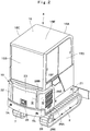
Fig. 1 is a front view showing a small-sized hydraulic excavator according to an embodiment in the present invention. -
Fig. 2 is a perspective view showing the hydraulic excavator in a state where a working mechanism is removed as viewed from the right backward side. -
Fig. 3 is a perspective view showing the hydraulic excavator in a state where an engine cover and a heat exchanger cover in the hydraulic excavator are opened as viewed in a position similar toFig. 2 . -
Fig. 4 is an exploded perspective view showing a revolving frame and a support member. -
Fig. 5 is an exploded perspective view showing the revolving frame and an exterior cover. -
Fig. 6 is a perspective view showing a heat exchanger as a single unit. -
Fig. 7 is a perspective view showing a state where the engine cover and the heat exchanger cover are mounted on the revolving frame as viewed from the left forward side. -
Fig. 8 is a partially enlarged perspective view showing the heat exchanger cover, the lock mechanism, a fastening tool and the like inFig. 7 . -
Fig. 9 is a perspective view showing the lock mechanism as a single unit. -
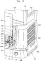
Fig. 10 is a perspective view showing a state where the engine cover is opened to operate the lock mechanism. -
Fig. 11 is a cross sectional view showing a state where the heat exchanger cover is locked in a closed position by the lock mechanism as viewed in a direction of arrows XI - XI inFig. 2 . -
Fig. 12 is a cross sectional view showing a state where the locked state by the lock mechanism is released to open the heat exchanger cover as viewed from a position as similar toFig. 11 . - Hereinafter, a small-sized hydraulic excavator taken as a representative example of small-sized construction machines according to an embodiment in the present invention will be in detail explained with reference to
Fig. 1 to Fig. 12 . - In
Fig. 1 , a small-sizedhydraulic excavator 1 is provided with an automotivelower traveling structure 2 of a crawler type, and an upper revolvingstructure 4 that is rotatably mounted on thelower traveling structure 2 through a revolvingdevice 3. A swingtype working mechanism 5, which includes aswing post 5A, aboom 5B, anarm 5C, abucket 5D and the like, is provided in the front side of the upper revolvingstructure 4 to be capable of swinging in a left-right direction, and thisworking mechanism 5 is used to perform an excavating work of earth and sand, and the like. Here, the small-sizedhydraulic excavator 1 is loaded on a small-sized truck to be transported to a working site and is used for a demolition work of the inside of a building, an excavating work in a narrow area of an urban area or the like. Therefore, a total weight of the small-sizedhydraulic excavator 1 is suppressed to approximately 0.7 to 8 tons, for example. - The upper revolving
structure 4 includes a revolvingframe 6, acounterweight 7, anengine 8, aheat exchanger 10, asupport member 14, acab 15 and anexterior cover 19, which will be described later. Here, since the small-sizedhydraulic excavator 1 is applied to a narrow working site such as the inside of a building or an urban area, for example, the upper revolvingstructure 4 is formed to be small. Therefore, in thehydraulic excavator 1, a space for arranging various kinds of mounted equipment on the revolvingframe 6 is narrow, and a rear position of thecab 15 is arranged on the upper side of theengine 8 and theheat exchanger 10. - The revolving
frame 6 is rotatably provided on thelower traveling structure 2 through the revolvingdevice 3. The revolvingframe 6 is formed as a support structural body and acts as a base of the upper revolvingstructure 4. As shown inFig. 4 andFig. 7 , the revolvingframe 6 includes abottom plate 6A formed in a rectangular shape to extend in a front-rear direction by using a thick steel plate or the like, and a leftvertical plate 6B and a rightvertical plate 6C arranged vertically to extend in the front-rear direction on thebottom plate 6A. - A
support bracket 6D is provided in a front end part of each of the leftvertical plate 6B and the rightvertical plate 6C. Thesupport bracket 6D swingably supports theswing post 5A provided in the base end of theworking mechanism 5 in the left-right direction. A leftrear bracket 6E and a rightrear bracket 6F are provided in rear end parts of the leftvertical plate 6B and the rightvertical plate 6C. Thecounterweight 7 to be described later is mounted in the leftrear bracket 6E and the rightrear bracket 6F, and a leftrear leg part 14C and a rightrear leg part 14D of thesupport member 14 to be described later are mounted therein. - A
horizontal plate 6G is vertically arranged in the intermediate part of thebottom plate 6A in the front-rear direction to extend in the left-right direction across the intermediate part of the leftvertical plate 6B in the front-rear direction. Thehorizontal plate 6G extends to a left end edge part of thebottom plate 6A over the leftvertical plate 6B from the rightvertical plate 6C. A leftfront leg part 14A of thesupport member 14 is mounted in a left end part of thehorizontal plate 6G. A support-member support bracket 6H erecting upward from thebottom plate 6A is mounted in a right end part of thebottom plate 6A positioned on an extension line of thehorizontal plate 6G. A rightfront leg part 14B of thesupport member 14 is mounted in the support-member support bracket 6H. - A heat
exchanger support base 6J is provided in the vicinity of a part of thebottom plate 6A in which the rightvertical plate 6C and the rightrear bracket 6F cross to extend along the rightvertical plate 6C in the front-rear direction (refer toFig. 7 ) . Theheat exchanger 10 to be described later is mounted on the heatexchanger support base 6J. Aleft cover bracket 6K is provided in a left end part of thebottom plate 6A positioned ahead of thehorizontal plate 6G to extend upward. A leftfront cover 20 to be described later is mounted in theleft cover bracket 6K. In addition, a rightfront cover bracket 6L is provided in a right front part of thebottom plate 6A to extend upward. Aright front cover 21 to be described later is mounted in the rightfront cover bracket 6L. - The
counterweight 7 is mounted on the rear end of the revolvingframe 6. Thecounterweight 7 acts as a weight balance to the workingmechanism 5, and is formed as a heavy load in a convex curved shape. Thecounterweight 7 is mounted in the leftrear bracket 6E and the rightrear bracket 6F in the revolvingframe 6 respectively by usingbolts 7A. Here, a left corner part and a right corner part of thecounterweight 7 respectively are chamfered in an arc shape not to become angular. Accordingly, thecounterweight 7 can avoid interference with the surrounding obstacles at the revolving movement of the upper revolvingstructure 4. - The
engine 8 is mounted closer to the rear side of thehorizontal plate 6G of the revolvingframe 6. Theengine 8 is arranged on the revolvingframe 6 in a horizontal state where a crank shaft (not shown) extends in the left-right direction. A hydraulic pump (not shown) is provided in the left side to theengine 8. The hydraulic pump is driven by theengine 8 to deliver pressurized oil toward various kinds of hydraulic actuators mounted on thehydraulic excavator 1. - A cooling
fan 9 is provided in the right side as one side in the left-right direction to theengine 8. The coolingfan 9 rotates adopting theengine 8 as a power source to suck in outside air as cooling air, and supplies the cooling air to theheat exchanger 10 to be described later. - The
heat exchanger 10 is positioned upstream side of the coolingfan 9 in a flowing direction of the cooling air and is provided on the revolvingframe 6. Theheat exchanger 10, as shown inFig. 6 , includes aframe body 11, aradiator 12 and anoil cooler 13, which will be described later. Theheat exchanger 10 is mounted on the heatexchanger support base 6J of the revolvingframe 6 and extends along the rightvertical plate 6C in the front-rear direction. - The
frame body 11 configures an outer shell of theheat exchanger 10, and supports theradiator 12, theoil cooler 13 and the like integrally. Theframe body 11 is formed in a rectangular frame shape as a whole by performing bending work to a steel plate member, for example. Theframe body 11 includes abottom plate 11A extending in the front-rear direction, and arear plate 11B arranged in the rear side of thebottom plate 11A and extending in the upper-lower direction. Therear plate 11B configures the rear end of theheat exchanger 10. Theheat exchanger 10 is arranged vertically on the revolvingframe 6 by mounting thebottom plate 11A of theframe body 11 on the heatexchanger support base 6J of the revolvingframe 6 using a plurality of bolts. - The
bottom plate 11A of theframe body 11 is provided with theradiator 12 and theoil cooler 13 mounted to line up in parallel to a flow of cooling air. That is, theradiator 12 and theoil cooler 13 are mounted on theframe body 11 to line up in the front-rear direction. In this state, apartition member 17 to be described later is mounted in theframe body 11 to extend from the surroundings of theradiator 12 and theoil cooler 13. - The
radiator 12 is mounted to theframe body 11 in a position closer to therear plate 11B. Theradiator 12 faces the coolingfan 9 in the left-right direction. Theradiator 12 is arranged to extend in the front-rear direction such that the flowing direction of the cooling air becomes the left-right direction. Theradiator 12 is connected to a water jacket (not shown) of theengine 8. Theradiator 12 is to cool engine cooling water, a temperature of which has increased by cooling theengine 8, by cooling air. - The
oil cooler 13 is mounted to theframe body 11 to be adjacent to the front side of theradiator 12. Theoil cooler 13 faces the coolingfan 9 in the left-right direction. Theoil cooler 13, as similar to theradiator 12, is arranged to extend in the front-rear direction such that the flowing direction of the cooling air becomes the left-right direction. Theoil cooler 13 cools the hydraulic oil, which is returned from various kinds of hydraulic actuators mounted on thehydraulic excavator 1 and a temperature of which has increased and, by cooling air, and the cooled hydraulic oil is circulated to an hydraulic oil tank. - The
support member 14 is arranged closer to the rear side than thehorizontal plate 6G of the revolvingframe 6 and is mounted to the revolvingframe 6 to bridge over theengine 8 and theheat exchanger 10. Thesupport member 14 supports the rear side of thecab 15 to be described later and is configured for a base of an operator's seat (any of them is not shown) arranged in the inside of thecab 15 to be mounted thereon. As shown inFig. 4 andFig. 5 , thesupport member 14 includes the leftfront leg part 14A, the rightfront leg part 14B, the leftrear leg part 14C, the rightrear leg part 14D and asupport base 14E mounted on the upper end of each of theleg parts - A lower end of the left
front leg part 14A is bolted to a left end part of thehorizontal plate 6G configuring part of the revolvingframe 6. An upper end of the leftfront leg part 14A is inclined obliquely toward the backward side. A lower end of the rightfront leg part 14B is bolted to the support-member support bracket 6H of the revolvingframe 6. An upper end of the rightfront leg part 14B is inclined obliquely toward the backward side. On the other hand, a lower end of the leftrear leg part 14C is bolted to the leftrear bracket 6E of the revolvingframe 6. An upper end of the leftrear leg part 14C extends upward. A lower end of the rightrear leg part 14D is bolted to the rightrear bracket 6F of the revolvingframe 6. An upper end of the rightrear leg part 14D extends upward. Here, afastening tool 31 to be described later is provided in the intermediate part of the rightrear leg part 14D in the upper-lower direction to project toward the backward side. - The
support base 14E is fixed to an upper end of each of the leftfront leg part 14A, the rightfront leg part 14B, the leftrear leg part 14C and the rightrear leg part 14D. Thesupport base 14E has a length dimension substantially equal to a width dimension of the revolvingframe 6 in the left-right direction, and connects the upper ends of theleg parts support base 14E extends in the left-right direction above theengine 8 and theheat exchanger 10, and supports the rear side of thecab 15 on the upper side to theengine 8 and theheat exchanger 10. - The
cab 15 is mounted on the revolvingframe 6 in a state of covering the revolvingframe 6 over a substantially entire region from above to define an operator's room. Thecab 15 has a length dimension in the front-rear direction having 70% to 90% or more of the upper revolvingstructure 4 in the front-rear direction, for example. Accordingly, occupant comfort in the inside of thecab 15 is enhanced in the small-sizedhydraulic excavator 1. As shown inFig. 1 to Fig. 3 , thecab 15 is formed in a boxy shape to be surrounded by afront surface part 15A, arear surface part 15B facing thefront surface part 15A in the front-rear direction, a leftside surface part 15C positioned in the left side between thefront surface part 15A and therear surface part 15B, a rightside surface part 15D facing the leftside surface part 15C and anupper surface part 15E for closing an upper end of each of thefront surface part 15A, therear surface part 15B, the leftside surface part 15C and the rightside surface part 15D. Further, a recessedpart 15F recessed toward the upper side and the front side is formed in a rear lower side of thecab 15, and thecab 15 is formed in a stepped boxy shape as a whole. - In a state where the
cab 15 is mounted on the revolvingframe 6, the recessedpart 15F in the rear side of thecab 15 is supported by thesupport base 14E of thesupport member 14 and covers theengine 8 and theheat exchanger 10 from above. Accordingly, thecab 15 is mounted on the revolvingframe 6 in a state of covering the revolvingframe 6 over a substantially entire region from above, thus making it possible to largely secure a residence space in the inside of thecab 15. On the other hand, the space formed between the revolvingframe 6 and thecab 15 becomes narrow. - As shown in
Fig. 3 , an equipmentdevice accommodating room 16 is formed between thebottom plate 6A of the revolvingframe 6 and the recessedpart 15F of thecab 15 to be covered with theexterior cover 19 to be described later. The equipmentdevice accommodating room 16 is partitioned into anengine room 16A for accommodating theengine 8 and the like and aheat exchanger room 16B for accommodating theheat exchanger 10 and the like across thepartition member 17 to be described later. Theengine room 16A is covered with anengine cover 23 to be described later to be capable of opening/closing. Theheat exchanger room 16B is covered with aheat exchanger cover 28 to be described later to be capable of opening/closing. - The
partition member 17 is provided integrally with theframe body 11 to extend from the surroundings of theradiator 12 and theoil cooler 13 configuring part of the heat exchanger 10 (refer toFig. 6 ). That is, thepartition member 17 forms an outer peripheral part of theframe body 11. Thepartition member 17 seals theengine room 16A in a state where theengine cover 23 is closed, and seals theheat exchanger room 16B in a state where theheat exchanger cover 28 is closed. Accordingly, thepartition member 17 defines the equipmentdevice accommodating room 16 into theengine room 16A and theheat exchanger room 16B. Aseal material 18 formed of an elastic material such as rubber and the like is provided on an outer peripheral edge of thepartition member 17. Theseal material 18 is to seal a clearance formed between the outer peripheral edge of thepartition member 17 and an inner peripheral surface of theengine cover 23 or the like when theengine cover 23 is closed (refer toFig. 11 ). - Thereby, the cooling air sucked in the
heat exchanger room 16B by the coolingfan 9 passes through theheat exchanger 10, and after that, is supplied to theengine room 16A. Accordingly, thepartition member 17 can block penetration of the cooling air into theheat exchanger room 16B from theengine room 16A to prevent the cooling air a temperature of which has increased in theengine room 16A from penetrating into theheat exchanger room 16B. As a result, a low-temperature cooling air is supplied into theheat exchanger room 16B from an exterior. - The
exterior cover 19 is arranged on the circumference of the revolvingframe 6 between thecounterweight 7 and thecab 15. Theexterior cover 19 covers mount equipment devices such as theengine 8, the coolingfan 9 and theheat exchanger 10 and the like, which are mounted on the revolvingframe 6. As shown inFig. 2 andFig. 5 , theexterior cover 19 includes theleft front cover 20, a rightfront cover 21, a leftrear cover 22, theengine cover 23 and theheat exchanger cover 28 to be described later. - The
left front cover 20 has a lower side that is arranged between the left end part and the front end part of thebottom plate 6A configuring part of the revolvingframe 6 and an upper side that is arranged between the leftside surface part 15C and thefront surface part 15A of thecab 15. Theleft front cover 20 is formed in an L-letter shape extending along the left end part and the front end part of thebottom plate 6A. Theleft front cover 20 is mounted to theleft cover bracket 6K of the revolvingframe 6 and the like. On the other hand, the rightfront cover 21 has a lower side that is arranged between the right end part and the front end part of thebottom plate 6A configuring part of the revolvingframe 6 and an upper side that is arranged between the rightside surface part 15D and thefront surface part 15A of thecab 15. The rightfront cover 21 is formed in an L-letter shape extending along the right end part and the front end part of thebottom plate 6A. The rightfront cover 21 is mounted to the rightfront cover bracket 6L of the revolvingframe 6 and the like. - The left
rear cover 22 has a lower side that is arranged between the left end part of thebottom plate 6A configuring part of the revolvingframe 6 and thecounterweight 7 and an upper side that is arranged in a position corresponding to the recessedpart 15F of the leftside surface part 15C of thecab 15. The leftrear cover 22 is formed in an L-letter shape bending along the left end part and the rear end part of thebottom plate 6A. Theleft front cover 22 is mounted fixedly to a bracket (not shown) provided in thesupport member 14, for example. The leftrear cover 22 covers theengine 8, a hydraulic pump (not shown) and the like accommodated in theengine room 16A from the left side. Here, a left corner part of the leftrear cover 22 is chamfered in an arc shape not to become angular. Accordingly, the left corner part of the leftrear cover 22 can avoid interference with the surrounding obstacles at the revolving movement of the upper revolvingstructure 4. - The
engine cover 23 is arranged between a part of therear surface part 15B of thecab 15 corresponding to the recessedpart 15F and thecounterweight 7 to be capable of opening/closing in the upper-lower direction. Theengine cover 23 is arranged between the leftrear cover 22 and theheat exchanger cover 28, and is bent in an arc shape along the rear surface of thecounterweight 7. Theengine cover 23 covers theengine 8 accommodated in theengine room 16A, theheat exchanger 10 accommodated in theheat exchanger room 16B, and the like from the rear side. As shown inFig. 7 andFig. 8 , theengine cover 23 is mounted to thesupport member 14 through alink mechanism 23A. Theengine cover 23 moves in the upper-lower direction between a closed position shown inFig. 2 and an opened position shown inFig. 3 . - When the
engine cover 23 is placed in the closed position as shown inFig. 2 , theengine room 16A is closed by theengine cover 23. On the other hand, when theengine cover 23 is placed in the opened position as shown inFig. 3 , theengine room 16A is released, making it possible to perform a maintenance work to theengine 8 and the like. - Here, as shown in
Fig. 7 , theengine cover 23 is provided with an enginecover lock mechanism 24 that holds theengine cover 23 in the closed state (closed position). The enginecover lock mechanism 24 has apaw member 24A that projects to the forward side from an inner side surface of theengine cover 23. Thepaw member 24A is engaged to a reverse U-letter-shapedhook 25 provided in thecounterweight 7 when theengine cover 23 is closed. As a result, theengine cover 23 is automatically held in the closed state. On the other hand, a lockrelease operation tool 26 is provided on an outer side surface of theengine cover 23. The lockrelease operation tool 26 releases the engaging state of thepaw member 24A to thehook 25. The lockrelease operation tool 26 is operated from the outside of theengine cover 23 in the closed position by using a key (not shown) or the like. Accordingly, thepaw member 24A of the enginecover lock mechanism 24 is disengaged from thehook 25, making it possible to open theengine cover 23 upward by thelink mechanism 23A. - Further, as shown in
Fig. 11 , aseal member 27 formed of an elastic material such as rubber and the like is provided on an outer peripheral edge of theengine cover 23. Theseal member 27 seals a clearance to theheat exchanger cover 28 when theengine cover 23 is closed. Accordingly, rainwater, dusts and the like can be suppressed from entering the equipmentdevice accommodating room 16 through the outer peripheral edge of theengine cover 23. - The
heat exchanger cover 28 has a lower side that is arranged between the right end part of thebottom plate 6A configuring part of the revolvingframe 6 and thecounterweight 7 and an upper side that is arranged in a part corresponding to the recessedpart 15F of the rightside surface part 15D of thecab 15 to be capable of opening/closing in the front-rear direction. Theheat exchanger cover 28 is formed in an L-letter shape along the right end part and the rear end part of thebottom plate 6A. Theheat exchanger cover 28 covers theheat exchanger 10 accommodated in theheat exchanger room 16B, and the like from the right side. A right corner part of theheat exchanger cover 28 is chamfered in an arc shape not to become angular. Accordingly, the right corner part of theheat exchanger cover 28 can avoid interference with the surrounding obstacles at the revolving movement of the upper revolvingstructure 4. - Here, the
heat exchanger cover 28 includes aright surface plate 28A and arear surface plate 28B bent in the left side toward theengine cover 23 from the rear end side of theright surface plate 28A. Theright surface plate 28A extends in the front-rear direction in a state of facing theradiator 12 in theheat exchanger 10 and the like. Therear surface plate 28B faces the frame body 11 (rear plate 11B) in theheat exchanger 10 in the front-rear direction. As shown inFig. 3 andFig. 7 , afront end 28C of the heat exchanger cover 28 (right surface plate 28A) in the front-rear direction is rotatably mounted in the rightfront leg part 14B of thesupport member 14 through ahinge member 29. As a result, arear end 28D of the heat exchanger cover 28 (rear surface plate 28B) becomes a free end. Therear end 28D is rotatable in the front-rear direction (horizontal direction) on a basis of thefront end 28C supported by thehinge member 29. Accordingly, theheat exchanger cover 28 is configured to open/close in the horizontal direction between the closed position shown inFig. 2 andFig. 11 and the opened position shown inFig. 3 . - A plurality of
air flowing openings 28E are formed in theright surface plate 28A of theheat exchanger cover 28 to line up in the upper-lower direction. At rotation of the coolingfan 9, outside air is sucked in the inside of theheat exchanger room 16B through each of theair flowing openings 28E. On the other hand, as shown inFig. 11 and Fig. 12 , a plate-shaped mountingseat 28G bent in an L-letter shape is fixed to aninner surface 28F positioned in the inside of anarrow space 30, which will be described later, of therear surface plate 28B. A heat exchangercover lock mechanism 32 to be described later is mounted to the mountingseat 28G. - As shown in
Fig. 2 andFig. 11 , in a state where both theengine cover 23 and theheat exchanger cover 28 are closed, therear end 28D of theheat exchanger cover 28 and the heat exchangercover lock mechanism 32 are covered with theengine cover 23 from backward. That is, therear end 28D of theheat exchanger cover 28 and aright end 23B of theengine cover 23 overlap in the front-rear direction. As a result, even when therear end 28D of theheat exchanger cover 28 rotates in the front-rear direction on a basis of thefront end 28C, therear end 28D of theheat exchanger cover 28 abuts on theright end 23B of theengine cover 23. Accordingly, as long as theengine cover 23 is held in the closed state, theheat exchanger cover 28 can be suppressed from opening inadvertently. - On the other hand, as shown by hatching in
Fig. 11 , in a state where both theengine cover 23 and theheat exchanger cover 28 are closed, thenarrow space 30 surrounded by theengine cover 23, theheat exchanger cover 28 and thepartition member 17 is formed closer to the rear side than theheat exchanger 10. Thenarrow space 30 usually acts as a dead space. The rightrear leg part 14D of thesupport member 14 is arranged in the inside of thenarrow space 30, as well as thefastening tool 31 to be described later and the heat exchangercover lock mechanism 32 are provided therein. - More specifically, the
narrow space 30 is formed as a space surrounded by anextension part 23C of theengine cover 23, anextension part 28H of theheat exchanger cover 28 and anextension part 17A of thepartition member 17. Theextension part 23C of theengine cover 23 is a part extended to theheat exchanger room 16B-side from thepartition member 17. Theextension part 28H of theheat exchanger cover 28 is a part extended closer to the rear side than therear plate 11B (rear end of the heat exchanger 10) of theframe body 11 configuring part of theheat exchanger 10. Theextension part 17A of thepartition member 17 is a part extended closer to the rear side than therear plate 11B of theheat exchanger 10. - The
fastening tool 31 is provided in the rightrear leg part 14D of thesupport member 14. In this case, thefastening tool 31 is arranged in a part closer to the upper side than the rightrear bracket 6F of the revolvingframe 6. Thefastening tool 31 is engaged to an engaginggroove 37 of alatch 36 to be described later. As shown inFig. 11 , thefastening tool 31 is formed of a columnar shaft body on which amale screw 31A is formed, and is mounted to be removable (replaceable) to the rightrear leg part 14D by usingbolts 31B. Thefastening tool 31 extends backward from the rear surface of the rightrear leg part 14D and a tip end of thefastening tool 31 projects into thenarrow space 30. - The heat exchanger
cover lock mechanism 32 is provided in the rear end side of theheat exchanger cover 28. The heat exchangercover lock mechanism 32 holds (locks) theheat exchanger cover 28 in the closed state. As shown inFig. 7 to Fig. 11 , the heat exchangercover lock mechanism 32 includes a mountingbase 33, thelatch 36, the engaginggroove 37, aspring member 38 and alock release pin 39, which will be described later. - The mounting
base 33 is formed of a rectangular flat plate extending in the upper-lower direction. The mountingbase 33 is fixed to the mountingseat 28G provided on theinner surface 28F of theheat exchanger cover 28 by usingbolts 33A. When theheat exchanger cover 28 is closed, the mountingbase 33 is arranged in the inside of thenarrow space 30. Asupport shaft 34 is fixed in the intermediate part of the mountingbase 33 in the upper-lower direction. Thesupport shaft 34 projects forward (to the heat exchanger 10-side) from the mountingbase 33. Aspring receiving plate 35 is fixed to the mountingbase 33 on the lower side of thesupport shaft 34. A notchedportion 35A is provided in thespring receiving plate 35, and one end side of thespring member 38 to be described later is hooked in the notchedportion 35A. - The
latch 36 is rotatably supported on thesupport shaft 34. Thelatch 36 rotates in the inside of thenarrow space 30 in the upper-lower direction to cause the engaginggroove 37 to be engaged to and disengaged from thefastening tool 31. Thelatch 36 includes abending plate 36A formed of a plate body bent in a crank shape, and a rectangularsupplementary plate 36B fixed on thebending plate 36A. Thesupplementary plate 36B faces a base end part 36A1 of thebending plate 36A by an interval in the front-rear direction. The base end part 36A1 of thebending plate 36A and thesupplementary plate 36B are rotatably inserted in thesupport shaft 34 in the upper-lower direction. - An arc-shaped cam surface 36A3 is provided in a position corresponding to the
fastening tool 31 on an outer peripheral edge of a tip end part 36A2 of thebending plate 36A. The cam surface 36A3 abuts on thefastening tool 31 when theheat exchanger cover 28 closes from the opened state. The tip end part 36A2 of thelatch 36 rotates upward at the center of thesupport shaft 34 along the shape of the cam surface 36A3 to guide anopen end 37A of the engaginggroove 37 to be described later toward thefastening tool 31. - The engaging
groove 37 is provided in the tip end part 36A2 of thebending plate 36A configuring part of thelatch 36. The engaginggroove 37 is engaged to thefastening tool 31. The engaginggroove 37 is formed by notching a lower end edge of the tip end part 36A2 of thebending plate 36A upward. A lower end of the engaginggroove 37 is formed as theopen end 37A opened downward in the proximate part of the cam surface 36A3 of thebending plate 36A. Accordingly, when theheat exchanger cover 28 closes from the opened state, the tip end part 36A2 of thelatch 36 gradually rotates upward at the center of thesupport shaft 34 along the shape of the cam surface 36A3. In addition, the tip end part 36A2 of thelatch 36 rotates downward at the center of thesupport shaft 34 due to engagement of theopen end 37A of the engaginggroove 37 to thefastening tool 31. Thus, when theheat exchanger cover 28 closes from the opened state, the engaginggroove 37 provided in the tip end part 36A2 of thelatch 36 is automatically engaged to thefastening tool 31 fixed to the rightrear leg part 14D of thesupport member 14. As a result, thelatch 36 can hold (lock) theheat exchanger cover 28 in the closed state. - It should be noted that
bolt insertion holes 33B (refer toFig. 9 ) formed in the mountingbase 33 each are set to have a hole diameter for forming an appropriate clearance to thebolt 33A. Thereby, even in a case where an assembly tolerance has variations at the time of mounting theheat exchanger cover 28 on thesupport member 14, it is possible to adjust a mounting position of the mountingbase 33 to theheat exchanger cover 28. Accordingly, thefastening tool 31 provided in thesupport member 14 and the engaginggroove 37 of the heat exchangercover lock mechanism 32 can be easily positioned. - The
spring member 38 is provided to wind around thesupport shaft 34 between the base end part 36A1 of thebending plate 36A and thesupplementary plate 36B that configure part of thelatch 36. Oneend 38A of thespring member 38 is hooked in thesupplementary plate 36B, and the other end (not shown) of thespring member 38 is hooked in thespring receiving plate 35. Thespring member 38 urges the tip end part 36A2 of the latch 36 (bendingplate 36A) in a direction of rotating downward at the center of thesupport shaft 34. As a result, in a state where theheat exchanger cover 28 is held in the closed state, the engaginggroove 37 of thelatch 36 can be suppressed from being disengaged from thefastening tool 31 inadvertently. - The
lock release pin 39 is positioned in the vicinity of the engaginggroove 37 to be provided in the tip end part 36A2 of thebending plate 36A configuring part of thelatch 36. Thelock release pin 39 projects backward from the tip end part 36A2 of thebending plate 36A. Thelock release pin 39 is operated upward to disengage the engaginggroove 37 of thelatch 36 from thefastening tool 31 against an urging force of thespring member 38. - Here, as shown in
Fig. 11 , in a state where both theengine cover 23 and theheat exchanger cover 28 are closed, the heat exchangercover lock mechanism 32 is covered with theengine cover 23 from backward. At this time, thefastening tool 31, the tip end part 36A2 of the latch 36 (bendingplate 36A) in which the engaginggroove 37 is formed and thelock release pin 39 are arranged in the left side to therear end 28D of theheat exchanger cover 28. Therefore, in a state where theengine cover 23 is opened upward, an operator can confirm a state where the engaginggroove 37 of thelatch 36 is engaged to thefastening tool 31 with a visual contact, and can easily operate the lock release pin 39 (refer toFig. 10 ). - The
hydraulic excavator 1 according to the present embodiment has the configuration as described above, and next, an operation thereof will be explained. - The small-sized hydraulic excavator 1 a total weight of which is approximately 0.7 to 8 tons is transported to a working site in a state of being loaded on a loading platform of the small-sized truck. When the
hydraulic excavator 1 is transported to the working site, an operator gets in the inside of thecab 15 to operate the lever/pedal for travel and the operating lever for work (any of them is not shown) arranged in the inside of thecab 15. Accordingly, thehydraulic excavator 1 self-travels to the desired working site, and after that, performs a demolition work of the inside of a building, a side ditch digging work in a narrow urban area and the like and an excavating work of earth and sand. - Here, the
hydraulic excavator 1 has a length dimension of thecab 15 in the front-rear direction that is for example, 70% to 90% or more of a length dimension of the upper revolvingstructure 4 in the front-rear direction. Therfore, thehydraulic excavator 1 can enhance occupant comfort in the inside of thecab 15. In addition, the left corner part and the right corner part of thecounterweight 7 are chamfered in an arc shape, and the left corner part of the leftrear cover 22 and the right corner part of theheat exchanger cover 28 configuring part of theexterior cover 19 are chamfered in an arc shape. Therefore, when the upper revolvingstructure 4 is revolved, thecounterweight 7 and theexterior cover 19 can be suppressed from colliding with surrounding structures, stumpages and the like. - Here, in the
hydraulic excavator 1 according to the present embodiment, thefront end 28C of theheat exchanger cover 28 covering theheat exchanger 10 is mounted to thesupport member 14 through thehinge member 29. Therefore, theheat exchanger cover 28 is formed of a horizontal-opening structure in which therear end 28D as the free end is rotatable in the front-rear direction on a basis of thefront end 28C. - In contrast thereto, in the present embodiment, as shown in
Fig. 2 andFig. 11 , in a case where both theengine cover 23 and theheat exchanger cover 28 are closed, therear end 28D of theheat exchanger cover 28 and the heat exchangercover lock mechanism 32 are covered with theengine cover 23 from backward. Accordingly, even if therear end 28D of theheat exchanger cover 28 will rotate in the front-rear direction on a basis of thefront end 28C, therear end 28D of theheat exchanger cover 28 abuts on theright end 23B of theengine cover 23. - Accordingly, as long as the
engine cover 23 holds the closed state by the enginecover lock mechanism 24, it is possible to suppress the heat exchanger cover 28 from opening inadvertently. As a result, even if the heat exchangercover lock mechanism 32 is out of order, there is no possibility that theheat exchanger cover 28 opens inadvertently by a revolving movement of the upper revolvingstructure 4. Accordingly, since it is possible to prevent the heat exchanger cover 28 from colliding with objects existing in the circumference of thehydraulic excavator 1, it is possible to protect theheat exchanger cover 28. - In addition, according to the present embodiment, in a state where both the
engine cover 23 and theheat exchanger cover 28 are closed, thenarrow space 30 surrounded by theengine cover 23, theheat exchanger cover 28 and thepartition member 17 is formed closer to the rear side than theheat exchanger 10. The heat exchangercover lock mechanism 32 is accommodated in thenarrow space 30. In the small-sizedhydraulic excavator 1, since thecab 15 is arranged to cover theengine 8 and theheat exchanger 10 from the upper side, the equipment device accommodating space on the revolvingframe 6 becomes narrow. In the present embodiment, however, it is possible to provide the heat exchangercover lock mechanism 32 effectively utilizing thenarrow space 30 that is usually supposed to be a dead space. - Further, as shown in
Fig. 11 , in a state where both theengine cover 23 and theheat exchanger cover 28 are closed, thefastening tool 31 accommodated in thenarrow space 30, the tip end part 36A2 of thelatch 36 in which the engaginggroove 37 is formed and thelock release pin 39 are arranged in the left side to therear end 28D of theheat exchanger cover 28. Therefore, as shown inFig. 10 , in a state where theengine cover 23 is opened upward, an operator can confirm a state where the engaginggroove 37 of thelatch 36 is engaged to thefastening tool 31 with a visual contact. In addition, an operator operates thelock release pin 39 to easily release a lock state of theheat exchanger cover 28, making it possible to quickly open theheat exchanger cover 28. As a result, when an operator performs a maintenance work to theheat exchanger 10 and the like accommodated in the inside of theheat exchanger room 16B, it is possible to enhance the workability. - Further, in a state where the
engine cover 23 is closed, the heat exchangercover lock mechanism 32 provided in theheat exchanger cover 28 can be covered and hidden with theengine cover 23. As a result, theheat exchanger cover 28 can be shown in a neat and fine form to enhance outside appearance quality (outside appearance beauty) of thehydraulic excavator 1. - In addition, in the present embodiment, the
partition member 17 is formed as a part of theframe body 11 of theheat exchanger 10 and integrally with theframe body 11. Thepartition member 17 is provided between theengine room 16A and theheat exchanger room 16B in the circumference of theheat exchanger 10. Thereby, in a state where both theengine cover 23 and theheat exchanger cover 28 are closed, theheat exchanger room 16B is partitioned from theengine room 16A by thepartition member 17. - Accordingly, the cooling air sucked in by the cooling
fan 9 passes through theheat exchanger 10, and thereby, is supplied to theengine room 16A from theheat exchanger room 16B. At this time, thepartition member 17 blocks the cooling air from penetrating into theheat exchanger room 16B from theengine room 16A. As a result, it is possible to prevent the cooling air a temperature of which has increased in theengine room 16A from penetrating into theheat exchanger room 16B to supply a low-temperature cooling air into theheat exchanger room 16B. - In addition, in the present embodiment, the
narrow space 30 is formed as a space surrounded by theextension part 23C of theengine cover 23 in the closed state that extends from thepartition member 17 to theheat exchanger room 16B-side, theextension part 28H of theheat exchanger cover 28 in the closed state that extends closer to the rear side than the rear end (rear plate 11B of the frame body 11) of theheat exchanger 10 and theextension part 17A of thepartition member 17 that extends closer to the rear side than the rear end of theheat exchanger 10. Accordingly, it is possible to arrange the heat exchangercover lock mechanism 32 effectively utilizing thenarrow space 30 that is usually supposed to be a dead space. - In addition, in the present embodiment, the
support member 14 is provided in the rear side of the revolvingframe 6 to support the rear side of thecab 15 and thefastening tool 31 is provided in thesupport member 14 to project into thenarrow space 30. The heat exchangercover lock mechanism 32 is configured to hold theheat exchanger cover 28 in the closed state by being engaged to thefastening tool 31 at the time of closing theheat exchanger cover 28. Accordingly, when theheat exchanger cover 28 is closed from the opened state, the engaginggroove 37 provided in the tip end part 36A2 of the latch 36 (bendingplate 36A) is automatically engaged to thefastening tool 31. As a result, when theheat exchanger cover 28 moves to the closed position, it is possible to automatically hold theheat exchanger cover 28 in the closed state by the heat exchangercover lock mechanism 32. - In addition, in the present embodiment, the heat exchanger
cover lock mechanism 32 includes the mountingbase 33 of theheat exchanger cover 28 that is provided on theinner surface 28F of theheat exchanger cover 28 positioned in the inside of thenarrow space 30, thelatch 36 that is supported on the mountingbase 33 through thesupport shaft 34 and is rotatable in the upper-lower direction in the inside of thenarrow space 30, the engaginggroove 37 that is provided in thelatch 36 and is engaged to thefastening tool 31 and thelock release pin 39 that is positioned in the vicinity of the engaginggroove 37 and is provided in thelatch 36 to be operated for disengaging the engaginggroove 37 from thefastening tool 31. Accordingly, when the engaginggroove 37 provided in thelatch 36 is engaged to thefastening tool 31, theheat exchanger cover 28 is locked to the closed position. In addition, the lock state of theheat exchanger cover 28 is released by operating thelock release pin 39 to disengage the engaginggroove 37 of thelatch 36 from thefastening tool 31. - It should be noted that the embodiment is explained by taking the small-sized
hydraulic excavator 1 provided with the workingmechanism 5 for an excavating work including thebucket 5D as a small-sized construction machine, as an example. However, the present invention is not limited thereto, but may be applied to a small-sized hydraulic excavator provided with working tools other than the bucket, such as grapples and rock drills and the like. -
- 1:
- Hydraulic excavator (Small-sized construction machine)
- 2:
- Lower traveling structure
- 4:
- Upper revolving structure
- 5:
- Working mechanism
- 6:
- Revolving frame
- 7:
- Counterweight
- 8:
- Engine
- 9:
- Cooling fan
- 10:
- Heat exchanger
- 11B:
- Rear plate (Rear end of heat exchanger)
- 14:
- Support member
- 15:
- Cab
- 15B:
- Rear surface part (Rear surface)
- 15F:
- Recessed part
- 16:
- Equipment device accommodating room
- 16A:
- Engine room
- 16B:
- Heat exchanger room
- 17:
- Partition member
- 17A, 23C, 28H:
- Extension part
- 23:
- Engine cover
- 28:
- Heat exchanger cover
- 28D:
- Rear end
- 28F:
- Inner surface
- 30:
- Narrow space
- 31:
- Fastening tool
- 32:
- Heat exchanger cover lock mechanism (Lock mechanism)
- 33:
- Mounting base
- 34:
- Support shaft
- 36:
- Latch
- 37:
- Engaging groove
- 39:
- Lock release pin
Claims (6)
- A small-sized construction machine comprising:an automotive lower traveling structure;an upper revolving structure that is rotatably mounted on said lower traveling structure; anda working mechanism that is provided in the front side of said upper revolving structure, whereinsaid upper revolving structure includes:a revolving frame that is formed as a support structural body;a counterweight that is mounted in the rear side of said revolving frame for acting as a weight balance to said working mechanism;an engine that is positioned in the front side to said counterweight and is mounted on said revolving frame in a horizontal state of extending in a left-right direction;a cooling fan that is provided on one side of said engine in the left-right direction to suck in outside air as cooling air;a heat exchanger that is positioned upstream of said cooling fan in a flow direction of the cooling air and is mounted on said revolving frame to cool fluid by the cooling air;a stepped boxy cab that is provided on said revolving frame and has a recessed part formed by notching a rear side of a side surface and a rear surface;an engine cover that is provided between said counterweight and the rear surface of said cab to be capable of opening/closing in an upper-lower direction for inspection of said engine; anda heat exchanger cover that is provided between the rear side of the side surface of said cab and said revolving frame to be capable of opening/closing for inspection of said heat exchanger, characterized in that:said heat exchanger cover is formed of a horizontal-opening structure of being rotatable to said revolving frame with a front end in a front-rear direction as a fulcrum and a rear end in the front-rear direction as a free end; anda lock mechanism is provided on a rear end side of said heat exchanger cover to hold said heat exchanger cover in a closed state, whereinin a state where both said heat exchanger cover and said engine cover are closed, said engine cover covers the rear end of said heat exchanger cover and said lock mechanism from backward.
- The small-sized construction machine according to claim 1, wherein
a partition member is provided in the circumference of said heat exchanger for partition between an engine room in which said engine is accommodated and that is opened/closed by said engine cover and a heat exchanger room in which said heat exchanger is accommodated and that opened/closed by said heat exchanger cover, wherein
in a state where both said engine cover and said heat exchanger cover are closed, cooling air having entered into said heat exchanger room passes through said heat exchanger and then, flows toward said engine room. - The small-sized construction machine according to claim 2, wherein
a narrow space is formed closer to the rear side than said heat exchanger, the narrow space being surrounded by said engine cover, said heat exchanger cover and said partition member in a state where said engine cover and said heat exchanger cover are closed, wherein
said lock mechanism is accommodated in the inside of said narrow space. - The small-sized construction machine according to claim 3, wherein
said narrow space includes a space that is surrounded by a part of said engine cover in the closed state extending to said heat exchanger room-side from said partition member, a part of said heat exchanger cover in the closed state extending closer to the rear side than the rear end of said heat exchanger and a part of said partition member extending closer to the rear side than the rear end of said heat exchanger. - The small-sized construction machine according to claim 3, wherein
a support member is provided in the rear side of said revolving frame to support the rear side of said cab, and
a fastening tool projecting into said narrow space is provided in said support member, wherein
said lock mechanism is engaged to said fastening tool at the time of closing said heat exchanger cover to hold said heat exchanger cover in the closed state. - The small-sized construction machine according to claim 5, wherein
said lock mechanism includes:a mounting base that is provided on an inner surface of said heat exchanger cover positioned in the inside of said narrow space;a latch that is supported on said mounting base through a support shaft and is rotatable in an upper-lower direction in the inside of said narrow space;an engaging groove that is provided in said latch and is engaged to said fastening tool; anda lock release pin that is positioned in the vicinity of said engaging groove and is provided in said latch to be operated for disengaging said engaging groove from said fastening tool.
Applications Claiming Priority (2)
| Application Number | Priority Date | Filing Date | Title |
|---|---|---|---|
| JP2016009063A JP6495193B2 (en) | 2016-01-20 | 2016-01-20 | Small construction machinery |
| PCT/JP2016/076315 WO2017126155A1 (en) | 2016-01-20 | 2016-09-07 | Compact construction machinery |
Publications (3)
| Publication Number | Publication Date |
|---|---|
| EP3406804A1 true EP3406804A1 (en) | 2018-11-28 |
| EP3406804A4 EP3406804A4 (en) | 2019-08-07 |
| EP3406804B1 EP3406804B1 (en) | 2021-11-03 |
Family
ID=59362260
Family Applications (1)
| Application Number | Title | Priority Date | Filing Date |
|---|---|---|---|
| EP16886395.9A Active EP3406804B1 (en) | 2016-01-20 | 2016-09-07 | Compact construction machinery |
Country Status (6)
| Country | Link |
|---|---|
| US (1) | US10961689B2 (en) |
| EP (1) | EP3406804B1 (en) |
| JP (1) | JP6495193B2 (en) |
| KR (1) | KR102082840B1 (en) |
| CN (1) | CN108138462B (en) |
| WO (1) | WO2017126155A1 (en) |
Cited By (1)
| Publication number | Priority date | Publication date | Assignee | Title |
|---|---|---|---|---|
| EP4467728A1 (en) * | 2023-05-25 | 2024-11-27 | Kässbohrer Geländefahrzeug AG | Tracked vehicle |
Families Citing this family (8)
| Publication number | Priority date | Publication date | Assignee | Title |
|---|---|---|---|---|
| US10550546B2 (en) * | 2018-03-26 | 2020-02-04 | Komatsu Ltd. | Cover of work vehicle, cab of work vehicle, and work vehicle |
| JP7100605B2 (en) * | 2019-04-25 | 2022-07-13 | 株式会社クボタ | Rectifying plate mounting structure and work vehicle |
| CN110468900B (en) * | 2019-08-27 | 2024-10-29 | 三一重机有限公司 | Cab protection device and excavator |
| JP6974920B2 (en) * | 2019-10-10 | 2021-12-01 | キャタピラー エス エー アール エル | Cooling fan arrangement structure |
| JP2022098754A (en) * | 2020-12-22 | 2022-07-04 | ヤンマーホールディングス株式会社 | Construction machinery |
| CN113309166B (en) * | 2021-05-27 | 2022-06-07 | 徐工集团工程机械股份有限公司科技分公司 | Multipurpose upper cover mechanism for skid steer loaders |
| US12077938B2 (en) * | 2021-10-12 | 2024-09-03 | Caterpillar Inc. | Secondary control system and method for mounting with service orientation |
| US12415573B2 (en) * | 2022-12-13 | 2025-09-16 | Cnh Industrial America Llc | Off-road vehicle with a dual-hinge hood assembly |
Family Cites Families (19)
| Publication number | Priority date | Publication date | Assignee | Title |
|---|---|---|---|---|
| JP3572719B2 (en) * | 1995-05-16 | 2004-10-06 | コベルコ建機株式会社 | Hydraulic working machine |
| JP2000080676A (en) * | 1998-09-04 | 2000-03-21 | Hitachi Constr Mach Co Ltd | Construction machinery |
| JP2001348909A (en) * | 2000-06-02 | 2001-12-21 | Shin Caterpillar Mitsubishi Ltd | Construction machinery |
| JP2002070075A (en) | 2000-08-25 | 2002-03-08 | Hitachi Constr Mach Co Ltd | Construction equipment |
| JP2002321651A (en) * | 2001-04-26 | 2002-11-05 | Hitachi Constr Mach Co Ltd | Opening/closing door locking device of construction machine |
| JP4226506B2 (en) * | 2004-03-29 | 2009-02-18 | 株式会社クボタ | Work control unit structure of a swing work machine |
| JP4276151B2 (en) * | 2004-09-15 | 2009-06-10 | 日立建機株式会社 | Construction machinery |
| KR20060060068A (en) * | 2004-11-30 | 2006-06-05 | 히다찌 겐끼 가부시키가이샤 | Pedal cover of construction machinery |
| US7388301B2 (en) * | 2005-10-12 | 2008-06-17 | Kobelco Construction Machinery Co., Ltd. | Construction machine |
| JP4142692B2 (en) * | 2006-02-07 | 2008-09-03 | 株式会社竹内製作所 | Battery arrangement structure of work vehicle |
| JP2007217922A (en) | 2006-02-15 | 2007-08-30 | Hitachi Constr Mach Co Ltd | Construction machinery |
| JP4527074B2 (en) * | 2006-03-13 | 2010-08-18 | ヤンマー株式会社 | Excavator |
| JP5172381B2 (en) * | 2008-02-22 | 2013-03-27 | 日立建機株式会社 | Construction machinery |
| JP2010168739A (en) * | 2009-01-20 | 2010-08-05 | Hitachi Constr Mach Co Ltd | Construction machinery |
| JP5562763B2 (en) * | 2009-08-27 | 2014-07-30 | 日立建機株式会社 | Construction machinery |
| KR101815331B1 (en) * | 2010-06-15 | 2018-01-04 | 가부시키가이샤 히다치 겡키 티에라 | Electric construction machine |
| JP2014080828A (en) * | 2012-10-18 | 2014-05-08 | Hitachi Constr Mach Co Ltd | Construction machine |
| JP6012760B2 (en) * | 2012-12-05 | 2016-10-25 | 日立建機株式会社 | Construction machinery |
| JP2015140633A (en) * | 2014-01-30 | 2015-08-03 | コベルコ建機株式会社 | Construction machine |
-
2016
- 2016-01-20 JP JP2016009063A patent/JP6495193B2/en active Active
- 2016-09-07 US US15/757,840 patent/US10961689B2/en active Active
- 2016-09-07 KR KR1020187006472A patent/KR102082840B1/en active Active
- 2016-09-07 CN CN201680051236.5A patent/CN108138462B/en active Active
- 2016-09-07 EP EP16886395.9A patent/EP3406804B1/en active Active
- 2016-09-07 WO PCT/JP2016/076315 patent/WO2017126155A1/en not_active Ceased
Cited By (1)
| Publication number | Priority date | Publication date | Assignee | Title |
|---|---|---|---|---|
| EP4467728A1 (en) * | 2023-05-25 | 2024-11-27 | Kässbohrer Geländefahrzeug AG | Tracked vehicle |
Also Published As
| Publication number | Publication date |
|---|---|
| WO2017126155A1 (en) | 2017-07-27 |
| EP3406804B1 (en) | 2021-11-03 |
| KR102082840B1 (en) | 2020-02-28 |
| CN108138462A (en) | 2018-06-08 |
| KR20180031043A (en) | 2018-03-27 |
| CN108138462B (en) | 2020-07-14 |
| US10961689B2 (en) | 2021-03-30 |
| US20200232184A1 (en) | 2020-07-23 |
| JP2017128928A (en) | 2017-07-27 |
| EP3406804A4 (en) | 2019-08-07 |
| JP6495193B2 (en) | 2019-04-03 |
Similar Documents
| Publication | Publication Date | Title |
|---|---|---|
| EP3406804B1 (en) | Compact construction machinery | |
| EP1943121B1 (en) | Cooling device for construction machine | |
| JP5173976B2 (en) | Construction equipment front guard mounting device | |
| JP2007092455A (en) | Construction machinery | |
| JP3956913B2 (en) | Work machine | |
| JP2010168739A (en) | Construction machinery | |
| JP2017115558A (en) | Small-sized construction machine | |
| EP3719214A1 (en) | Cab for working machine, and working machine | |
| JP6797144B2 (en) | Construction machinery | |
| JP5054802B2 (en) | Construction machinery | |
| JP6543095B2 (en) | Construction machinery | |
| JP2017155493A (en) | Construction machine and method for attaching engine cover of construction machine | |
| JP4908392B2 (en) | Construction machinery | |
| JP2011012509A (en) | Construction machine | |
| WO2014065211A1 (en) | Construction machinery | |
| JP7301720B2 (en) | construction machinery | |
| JP6522566B2 (en) | Small hydraulic shovel | |
| JP2007217922A (en) | Construction machinery | |
| JP4611846B2 (en) | Construction machine manufacturing method | |
| KR101301153B1 (en) | Fixing device of door for heavy equipment | |
| JP7643375B2 (en) | Construction Machinery | |
| JP2020133285A (en) | Work machine | |
| JP2007247144A (en) | Excavating work machine | |
| JP4703369B2 (en) | Work machine | |
| JP2025029617A (en) | Work vehicles |
Legal Events
| Date | Code | Title | Description |
|---|---|---|---|
| STAA | Information on the status of an ep patent application or granted ep patent |
Free format text: STATUS: THE INTERNATIONAL PUBLICATION HAS BEEN MADE |
|
| PUAI | Public reference made under article 153(3) epc to a published international application that has entered the european phase |
Free format text: ORIGINAL CODE: 0009012 |
|
| STAA | Information on the status of an ep patent application or granted ep patent |
Free format text: STATUS: REQUEST FOR EXAMINATION WAS MADE |
|
| 17P | Request for examination filed |
Effective date: 20180328 |
|
| AK | Designated contracting states |
Kind code of ref document: A1 Designated state(s): AL AT BE BG CH CY CZ DE DK EE ES FI FR GB GR HR HU IE IS IT LI LT LU LV MC MK MT NL NO PL PT RO RS SE SI SK SM TR |
|
| AX | Request for extension of the european patent |
Extension state: BA ME |
|
| DAV | Request for validation of the european patent (deleted) | ||
| DAX | Request for extension of the european patent (deleted) | ||
| A4 | Supplementary search report drawn up and despatched |
Effective date: 20190708 |
|
| RIC1 | Information provided on ipc code assigned before grant |
Ipc: E02F 3/32 20060101ALI20190702BHEP Ipc: E02F 9/00 20060101AFI20190702BHEP Ipc: E02F 9/08 20060101ALI20190702BHEP Ipc: B62D 25/10 20060101ALI20190702BHEP Ipc: B62D 25/12 20060101ALI20190702BHEP |
|
| STAA | Information on the status of an ep patent application or granted ep patent |
Free format text: STATUS: EXAMINATION IS IN PROGRESS |
|
| 17Q | First examination report despatched |
Effective date: 20200401 |
|
| GRAP | Despatch of communication of intention to grant a patent |
Free format text: ORIGINAL CODE: EPIDOSNIGR1 |
|
| STAA | Information on the status of an ep patent application or granted ep patent |
Free format text: STATUS: GRANT OF PATENT IS INTENDED |
|
| INTG | Intention to grant announced |
Effective date: 20210429 |
|
| GRAS | Grant fee paid |
Free format text: ORIGINAL CODE: EPIDOSNIGR3 |
|
| GRAA | (expected) grant |
Free format text: ORIGINAL CODE: 0009210 |
|
| STAA | Information on the status of an ep patent application or granted ep patent |
Free format text: STATUS: THE PATENT HAS BEEN GRANTED |
|
| AK | Designated contracting states |
Kind code of ref document: B1 Designated state(s): AL AT BE BG CH CY CZ DE DK EE ES FI FR GB GR HR HU IE IS IT LI LT LU LV MC MK MT NL NO PL PT RO RS SE SI SK SM TR |
|
| REG | Reference to a national code |
Ref country code: GB Ref legal event code: FG4D |
|
| REG | Reference to a national code |
Ref country code: AT Ref legal event code: REF Ref document number: 1444049 Country of ref document: AT Kind code of ref document: T Effective date: 20211115 Ref country code: CH Ref legal event code: EP |
|
| REG | Reference to a national code |
Ref country code: DE Ref legal event code: R096 Ref document number: 602016065871 Country of ref document: DE |
|
| REG | Reference to a national code |
Ref country code: IE Ref legal event code: FG4D |
|
| REG | Reference to a national code |
Ref country code: LT Ref legal event code: MG9D |
|
| REG | Reference to a national code |
Ref country code: NL Ref legal event code: MP Effective date: 20211103 |
|
| REG | Reference to a national code |
Ref country code: AT Ref legal event code: MK05 Ref document number: 1444049 Country of ref document: AT Kind code of ref document: T Effective date: 20211103 |
|
| PG25 | Lapsed in a contracting state [announced via postgrant information from national office to epo] |
Ref country code: RS Free format text: LAPSE BECAUSE OF FAILURE TO SUBMIT A TRANSLATION OF THE DESCRIPTION OR TO PAY THE FEE WITHIN THE PRESCRIBED TIME-LIMIT Effective date: 20211103 Ref country code: LT Free format text: LAPSE BECAUSE OF FAILURE TO SUBMIT A TRANSLATION OF THE DESCRIPTION OR TO PAY THE FEE WITHIN THE PRESCRIBED TIME-LIMIT Effective date: 20211103 Ref country code: FI Free format text: LAPSE BECAUSE OF FAILURE TO SUBMIT A TRANSLATION OF THE DESCRIPTION OR TO PAY THE FEE WITHIN THE PRESCRIBED TIME-LIMIT Effective date: 20211103 Ref country code: BG Free format text: LAPSE BECAUSE OF FAILURE TO SUBMIT A TRANSLATION OF THE DESCRIPTION OR TO PAY THE FEE WITHIN THE PRESCRIBED TIME-LIMIT Effective date: 20220203 Ref country code: AT Free format text: LAPSE BECAUSE OF FAILURE TO SUBMIT A TRANSLATION OF THE DESCRIPTION OR TO PAY THE FEE WITHIN THE PRESCRIBED TIME-LIMIT Effective date: 20211103 |
|
| PG25 | Lapsed in a contracting state [announced via postgrant information from national office to epo] |
Ref country code: IS Free format text: LAPSE BECAUSE OF FAILURE TO SUBMIT A TRANSLATION OF THE DESCRIPTION OR TO PAY THE FEE WITHIN THE PRESCRIBED TIME-LIMIT Effective date: 20220303 Ref country code: SE Free format text: LAPSE BECAUSE OF FAILURE TO SUBMIT A TRANSLATION OF THE DESCRIPTION OR TO PAY THE FEE WITHIN THE PRESCRIBED TIME-LIMIT Effective date: 20211103 Ref country code: PT Free format text: LAPSE BECAUSE OF FAILURE TO SUBMIT A TRANSLATION OF THE DESCRIPTION OR TO PAY THE FEE WITHIN THE PRESCRIBED TIME-LIMIT Effective date: 20220303 Ref country code: PL Free format text: LAPSE BECAUSE OF FAILURE TO SUBMIT A TRANSLATION OF THE DESCRIPTION OR TO PAY THE FEE WITHIN THE PRESCRIBED TIME-LIMIT Effective date: 20211103 Ref country code: NO Free format text: LAPSE BECAUSE OF FAILURE TO SUBMIT A TRANSLATION OF THE DESCRIPTION OR TO PAY THE FEE WITHIN THE PRESCRIBED TIME-LIMIT Effective date: 20220203 Ref country code: NL Free format text: LAPSE BECAUSE OF FAILURE TO SUBMIT A TRANSLATION OF THE DESCRIPTION OR TO PAY THE FEE WITHIN THE PRESCRIBED TIME-LIMIT Effective date: 20211103 Ref country code: LV Free format text: LAPSE BECAUSE OF FAILURE TO SUBMIT A TRANSLATION OF THE DESCRIPTION OR TO PAY THE FEE WITHIN THE PRESCRIBED TIME-LIMIT Effective date: 20211103 Ref country code: HR Free format text: LAPSE BECAUSE OF FAILURE TO SUBMIT A TRANSLATION OF THE DESCRIPTION OR TO PAY THE FEE WITHIN THE PRESCRIBED TIME-LIMIT Effective date: 20211103 Ref country code: GR Free format text: LAPSE BECAUSE OF FAILURE TO SUBMIT A TRANSLATION OF THE DESCRIPTION OR TO PAY THE FEE WITHIN THE PRESCRIBED TIME-LIMIT Effective date: 20220204 Ref country code: ES Free format text: LAPSE BECAUSE OF FAILURE TO SUBMIT A TRANSLATION OF THE DESCRIPTION OR TO PAY THE FEE WITHIN THE PRESCRIBED TIME-LIMIT Effective date: 20211103 |
|
| PG25 | Lapsed in a contracting state [announced via postgrant information from national office to epo] |
Ref country code: SM Free format text: LAPSE BECAUSE OF FAILURE TO SUBMIT A TRANSLATION OF THE DESCRIPTION OR TO PAY THE FEE WITHIN THE PRESCRIBED TIME-LIMIT Effective date: 20211103 Ref country code: SK Free format text: LAPSE BECAUSE OF FAILURE TO SUBMIT A TRANSLATION OF THE DESCRIPTION OR TO PAY THE FEE WITHIN THE PRESCRIBED TIME-LIMIT Effective date: 20211103 Ref country code: RO Free format text: LAPSE BECAUSE OF FAILURE TO SUBMIT A TRANSLATION OF THE DESCRIPTION OR TO PAY THE FEE WITHIN THE PRESCRIBED TIME-LIMIT Effective date: 20211103 Ref country code: EE Free format text: LAPSE BECAUSE OF FAILURE TO SUBMIT A TRANSLATION OF THE DESCRIPTION OR TO PAY THE FEE WITHIN THE PRESCRIBED TIME-LIMIT Effective date: 20211103 Ref country code: DK Free format text: LAPSE BECAUSE OF FAILURE TO SUBMIT A TRANSLATION OF THE DESCRIPTION OR TO PAY THE FEE WITHIN THE PRESCRIBED TIME-LIMIT Effective date: 20211103 Ref country code: CZ Free format text: LAPSE BECAUSE OF FAILURE TO SUBMIT A TRANSLATION OF THE DESCRIPTION OR TO PAY THE FEE WITHIN THE PRESCRIBED TIME-LIMIT Effective date: 20211103 |
|
| REG | Reference to a national code |
Ref country code: DE Ref legal event code: R097 Ref document number: 602016065871 Country of ref document: DE |
|
| PLBE | No opposition filed within time limit |
Free format text: ORIGINAL CODE: 0009261 |
|
| STAA | Information on the status of an ep patent application or granted ep patent |
Free format text: STATUS: NO OPPOSITION FILED WITHIN TIME LIMIT |
|
| 26N | No opposition filed |
Effective date: 20220804 |
|
| PG25 | Lapsed in a contracting state [announced via postgrant information from national office to epo] |
Ref country code: AL Free format text: LAPSE BECAUSE OF FAILURE TO SUBMIT A TRANSLATION OF THE DESCRIPTION OR TO PAY THE FEE WITHIN THE PRESCRIBED TIME-LIMIT Effective date: 20211103 |
|
| PG25 | Lapsed in a contracting state [announced via postgrant information from national office to epo] |
Ref country code: SI Free format text: LAPSE BECAUSE OF FAILURE TO SUBMIT A TRANSLATION OF THE DESCRIPTION OR TO PAY THE FEE WITHIN THE PRESCRIBED TIME-LIMIT Effective date: 20211103 |
|
| PG25 | Lapsed in a contracting state [announced via postgrant information from national office to epo] |
Ref country code: MC Free format text: LAPSE BECAUSE OF FAILURE TO SUBMIT A TRANSLATION OF THE DESCRIPTION OR TO PAY THE FEE WITHIN THE PRESCRIBED TIME-LIMIT Effective date: 20211103 |
|
| REG | Reference to a national code |
Ref country code: CH Ref legal event code: PL |
|
| REG | Reference to a national code |
Ref country code: BE Ref legal event code: MM Effective date: 20220930 |
|
| PG25 | Lapsed in a contracting state [announced via postgrant information from national office to epo] |
Ref country code: IT Free format text: LAPSE BECAUSE OF FAILURE TO SUBMIT A TRANSLATION OF THE DESCRIPTION OR TO PAY THE FEE WITHIN THE PRESCRIBED TIME-LIMIT Effective date: 20211103 |
|
| PG25 | Lapsed in a contracting state [announced via postgrant information from national office to epo] |
Ref country code: LU Free format text: LAPSE BECAUSE OF NON-PAYMENT OF DUE FEES Effective date: 20220907 |
|
| PG25 | Lapsed in a contracting state [announced via postgrant information from national office to epo] |
Ref country code: LI Free format text: LAPSE BECAUSE OF NON-PAYMENT OF DUE FEES Effective date: 20220930 Ref country code: IE Free format text: LAPSE BECAUSE OF NON-PAYMENT OF DUE FEES Effective date: 20220907 Ref country code: FR Free format text: LAPSE BECAUSE OF NON-PAYMENT OF DUE FEES Effective date: 20220930 Ref country code: CH Free format text: LAPSE BECAUSE OF NON-PAYMENT OF DUE FEES Effective date: 20220930 |
|
| PG25 | Lapsed in a contracting state [announced via postgrant information from national office to epo] |
Ref country code: BE Free format text: LAPSE BECAUSE OF NON-PAYMENT OF DUE FEES Effective date: 20220930 |
|
| PG25 | Lapsed in a contracting state [announced via postgrant information from national office to epo] |
Ref country code: HU Free format text: LAPSE BECAUSE OF FAILURE TO SUBMIT A TRANSLATION OF THE DESCRIPTION OR TO PAY THE FEE WITHIN THE PRESCRIBED TIME-LIMIT; INVALID AB INITIO Effective date: 20160907 |
|
| PG25 | Lapsed in a contracting state [announced via postgrant information from national office to epo] |
Ref country code: CY Free format text: LAPSE BECAUSE OF FAILURE TO SUBMIT A TRANSLATION OF THE DESCRIPTION OR TO PAY THE FEE WITHIN THE PRESCRIBED TIME-LIMIT Effective date: 20211103 |
|
| PG25 | Lapsed in a contracting state [announced via postgrant information from national office to epo] |
Ref country code: MK Free format text: LAPSE BECAUSE OF FAILURE TO SUBMIT A TRANSLATION OF THE DESCRIPTION OR TO PAY THE FEE WITHIN THE PRESCRIBED TIME-LIMIT Effective date: 20211103 |
|
| PG25 | Lapsed in a contracting state [announced via postgrant information from national office to epo] |
Ref country code: MT Free format text: LAPSE BECAUSE OF FAILURE TO SUBMIT A TRANSLATION OF THE DESCRIPTION OR TO PAY THE FEE WITHIN THE PRESCRIBED TIME-LIMIT Effective date: 20211103 |
|
| PGFP | Annual fee paid to national office [announced via postgrant information from national office to epo] |
Ref country code: DE Payment date: 20250730 Year of fee payment: 10 |
|
| PGFP | Annual fee paid to national office [announced via postgrant information from national office to epo] |
Ref country code: GB Payment date: 20250731 Year of fee payment: 10 |
|
| PG25 | Lapsed in a contracting state [announced via postgrant information from national office to epo] |
Ref country code: TR Free format text: LAPSE BECAUSE OF FAILURE TO SUBMIT A TRANSLATION OF THE DESCRIPTION OR TO PAY THE FEE WITHIN THE PRESCRIBED TIME-LIMIT Effective date: 20211103 |