EP3406558A1 - Machine assembly and elevator - Google Patents
Machine assembly and elevator Download PDFInfo
- Publication number
- EP3406558A1 EP3406558A1 EP18173301.5A EP18173301A EP3406558A1 EP 3406558 A1 EP3406558 A1 EP 3406558A1 EP 18173301 A EP18173301 A EP 18173301A EP 3406558 A1 EP3406558 A1 EP 3406558A1
- Authority
- EP
- European Patent Office
- Prior art keywords
- elevator
- tractors
- tractor assembly
- tractor
- rack
- Prior art date
- Legal status (The legal status is an assumption and is not a legal conclusion. Google has not performed a legal analysis and makes no representation as to the accuracy of the status listed.)
- Withdrawn
Links
Images


Classifications
-
- B—PERFORMING OPERATIONS; TRANSPORTING
- B66—HOISTING; LIFTING; HAULING
- B66B—ELEVATORS; ESCALATORS OR MOVING WALKWAYS
- B66B11/00—Main component parts of lifts in, or associated with, buildings or other structures
- B66B11/0005—Constructional features of hoistways
-
- B—PERFORMING OPERATIONS; TRANSPORTING
- B66—HOISTING; LIFTING; HAULING
- B66B—ELEVATORS; ESCALATORS OR MOVING WALKWAYS
- B66B11/00—Main component parts of lifts in, or associated with, buildings or other structures
- B66B11/02—Cages, i.e. cars
- B66B11/026—Attenuation system for shocks, vibrations, imbalance, e.g. passengers on the same side
- B66B11/028—Active systems
-
- B—PERFORMING OPERATIONS; TRANSPORTING
- B66—HOISTING; LIFTING; HAULING
- B66B—ELEVATORS; ESCALATORS OR MOVING WALKWAYS
- B66B11/00—Main component parts of lifts in, or associated with, buildings or other structures
- B66B11/0035—Arrangement of driving gear, e.g. location or support
-
- B—PERFORMING OPERATIONS; TRANSPORTING
- B66—HOISTING; LIFTING; HAULING
- B66B—ELEVATORS; ESCALATORS OR MOVING WALKWAYS
- B66B11/00—Main component parts of lifts in, or associated with, buildings or other structures
- B66B11/0035—Arrangement of driving gear, e.g. location or support
- B66B11/004—Arrangement of driving gear, e.g. location or support in the machine room
-
- B—PERFORMING OPERATIONS; TRANSPORTING
- B66—HOISTING; LIFTING; HAULING
- B66B—ELEVATORS; ESCALATORS OR MOVING WALKWAYS
- B66B11/00—Main component parts of lifts in, or associated with, buildings or other structures
- B66B11/0035—Arrangement of driving gear, e.g. location or support
- B66B11/0045—Arrangement of driving gear, e.g. location or support in the hoistway
-
- B—PERFORMING OPERATIONS; TRANSPORTING
- B66—HOISTING; LIFTING; HAULING
- B66B—ELEVATORS; ESCALATORS OR MOVING WALKWAYS
- B66B11/00—Main component parts of lifts in, or associated with, buildings or other structures
- B66B11/04—Driving gear ; Details thereof, e.g. seals
-
- B—PERFORMING OPERATIONS; TRANSPORTING
- B66—HOISTING; LIFTING; HAULING
- B66B—ELEVATORS; ESCALATORS OR MOVING WALKWAYS
- B66B11/00—Main component parts of lifts in, or associated with, buildings or other structures
- B66B11/04—Driving gear ; Details thereof, e.g. seals
- B66B11/043—Driving gear ; Details thereof, e.g. seals actuated by rotating motor; Details, e.g. ventilation
- B66B11/0484—Driving gear ; Details thereof, e.g. seals actuated by rotating motor; Details, e.g. ventilation with a clutch or a coupling system between several motors, e.g. switching different speeds, progressive starting, torque limitation, flywheel
Definitions
- the present invention relates to the field of elevators, and in particular, to a tractor assembly of an elevator.
- An objective of the present invention is to provide a tractor assembly that can achieve a high workload at a low cost.
- Another objective of the present invention is to provide an elevator that can achieve a high workload at a low cost.
- a tractor assembly which includes: a rack; multiple tractors; and multiple traction parts connected to an elevator car and an elevator counterweight respectively via the tractors; wherein the multiple tractors are mounted on the rack respectively, and are staggered along a horizontal direction; the vertical direction extends along an elevator hoistway, and the horizontal direction transects the elevator hoistway to extend.
- Particular embodiments may include any of the following optional features, alone or in combination: A part of the multiple tractors may be arranged above the elevator car, and the other part of the multiple tractors is arranged above the elevator counterweight.
- the rack may be constructed as a mounting frame in which multiple fixed traction pulleys are disposed.
- the traction parts may be connected to the elevator car and the elevator counterweight respectively via the tractors and the fixed traction pulleys.
- a rope ratio of the tractor assembly particularly may be 1:1.
- the rack may comprise multiple mounting frames in each of which a set of fixed traction pulleys is disposed respectively.
- the tractors each may correspond to a mounting frame and a set of fixed traction pulleys.
- a rope ratio of the tractor assembly particularly may be 1:1.
- Borders of the multiple mounting frames may be provided with connecting portions matched with each other.
- the tractor assembly further may comprise movable traction pulleys disposed on the elevator car and the elevator counterweight respectively.
- a rope ratio of the tractor assembly particularly may be 2:1.
- the rack may be provided with a mounting base plate, for providing mounting positions of the tractors.
- the traction parts may be steel belts or steel wire ropes.
- the tractor assembly may comprise two tractors.
- On/off of the multiple tractors may be controlled in a linked manner.
- an elevator which includes: an elevator car, an elevator counterweight, and a tractor assembly; wherein the tractor assembly includes a rack, multiple tractors, and multiple traction parts; the traction parts are connected to the elevator car and the elevator counterweight respectively via the tractors; wherein the multiple tractors are mounted on the rack respectively, and are staggered along a horizontal direction; the vertical direction extends along an elevator hoistway, and the horizontal direction transects the elevator hoistway to extend.
- Particular embodiments may include any of the following optional features, alone or in combination: A part of the multiple tractors may be arranged above the elevator car, and the other part of the multiple tractors may be arranged above the elevator counterweight.
- the rack may be constructed as a mounting frame in which multiple fixed traction pulleys are disposed; the traction parts may be connected to the elevator car and the elevator counterweight respectively via the tractors and the fixed traction pulleys; and a rope ratio of the tractor assembly particularly may be 1:1.
- the rack may comprise multiple mounting frames in each of which a set of fixed traction pulleys is disposed respectively.
- the tractors each may correspond to a mounting frame and a set of fixed traction pulleys.
- a rope ratio of the tractor assembly particularly may be 1:1.
- the elevator further may comprise movable traction pulleys disposed on the elevator car and the elevator counterweight respectively, and a rope ratio of the tractor assembly particularly may be 2:1.
- the rack may be provided with a mounting base plate, for providing mounting positions of the tractors.
- the traction parts may be steel belts.
- the tractor assembly may comprise two tractors.
- On/off of the multiple tractors may be be controlled in a linked manner.
- the rack may bemounted in the elevator hoistway or an elevator machine room.
- the elevator counterweight may be a lateral elevator counterweight and/or a rear elevator counterweight.
- the tractor assembly 100 includes: two racks 110a and 110b; two tractors 120a and 120b disposed in parallel; and two sets of traction belts 150a and 150b, wherein the two sets of traction belts 150a and 150b are connected to an elevator car 200 and an elevator counterweight 300 respectively via the two tractors 120a and 120b.
- the two tractors 120a and 120b are mounted on the racks 110a and 110b respectively, and are staggered along a horizontal direction.
- one of the two tractors 120a and 120b is arranged in a relative left position in the figure, while the other one is arranged in a relative right position in the figure.
- the space can be utilized more effectively, and mutual interference caused by movements of traction belts drawn by two tractors can be avoided.
- the tractor 120a on the left is actually arranged above the elevator car, while the tractor 120b on the right is actually arranged above the elevator counterweight.
- the tractor 120a will be directly connected to the car via traction
- the tractor 120b will be directly connected to the counterweight 300 via traction, thus avoiding the loss of force transmission caused by multiple transfer parts.
- FIG. 5 and FIG. 6 specific spatial arrangement positions of two tractors in FIG. 5 and FIG. 6 are only an example.
- the two tractors can also be both arranged above the elevator car, as long as they are staggered in the horizontal direction at the same time.
- the relative positions between the tractors and traction wheels can also be adjusted to adapt to different spatial requirements and transmission requirements.
- the two tractors 120a and 120b can also be staggered along a vertical direction. More specifically, one of the two tractors 120a and 120b is arranged in a relative upper position along a hoistway, while the other one is arranged in a relative lower position along the hoistway, such that the two tractors are staggered at a height H in the vertical direction.
- Such an arrangement manner can also utilize the space more effectively, and can avoid mutual interference caused by movements of traction belts drawn by the two tractors.
- the vertical direction and the horizontal direction described above should normally use the hoistway as a reference standard. That is, the arrangement along the vertical direction indicates staggering the multiple traction parts in an extending direction of the length of the hoistway, such that a part of the tractors is arranged higher than the other part.
- the arrangement along the horizontal direction indicates staggering the multiple traction parts in a direction of transecting the hoistway to extend, such that rotation axes of a part of the tractors and rotation axes of the other part of the tractors are staggered on the horizontal plane.
- the racks 110a and 110b each include a mounting frame.
- the mounting frame is constructed substantially as a rectangle and is formed by surrounding four borders.
- a set of fixed traction pulleys 130a and 130b is disposed on inner sides of two opposite long borders of the first mounting frame, and a set of fixed traction pulleys 130c and 130d is disposed on inner sides of two opposite long borders of the second mounting frame.
- the tractors 120a and 120b each correspond to a mounting frame and a set of fixed traction pulleys 130a, 130b, 130c and 130d respectively, thus forming two sets of traction drive systems that can move independently and have a rope ratio of 1:1.
- the elevator car and the elevator counterweight can be drawn by operating either or both of the two sets of traction drive systems.
- a set of fixed traction pulleys and a tractor can draw a limited number of traction belts, for example, the number is generally 4-5 at most.
- two sets of fixed traction pulleys and two tractors can draw up to 8-10 traction belts. This can effectively avoid sinking and oscillation problems occurring when the elevator is in an operating state or a stop state, thus improving the reliability and comfort of taking the elevator.
- the borders of the multiple mounting frames should be provided with connecting portions matched with each other, such that they can be connected into a whole.
- the whole rack into a mounting frame and dispose multiple fixed traction pulleys 130a, 130b, 130c and 130d in the mounting frame.
- the traction belts 150a and 150b are connected to the elevator car 200 and the elevator counterweight 300 respectively via the tractors 120a and 120b and the fixed traction pulleys 130a, 130b, 130c and 130d.
- the traction on the elevator car and the elevator counterweight can also be achieved.
- a rope ratio of the tractor assembly 100 is 1:1, thus reducing the quantity of the traction belts significantly.
- the traction belts are steel belts or steel wire ropes, the quantity of the steel belts or steel wire ropes can be reduced greatly.
- movable traction pulleys whose rope ratio is 2:1 can also be used.
- movable traction pulleys can be disposed on the elevator car 200 and the elevator counterweight 300 respectively, thus achieving the traction on the elevator car and the elevator counterweight.
- mounting base plates 140a and 140b may be further disposed on the racks 110a and 110b, for providing the tractors 120a and 120b with mounting positions.
- on/off of the multiple tractors should be able to be controlled in a linked manner.
- the elevator includes an elevator car 200, an elevator counterweight 300, and a tractor assembly 100.
- the tractor assembly 100 includes two racks 110a and 110b, two tractors 120a and 120b, and two sets of traction belts 150a and 150b.
- the two sets of traction belts 150a and 150b are connected to the elevator car 200 and the elevator counterweight 300 respectively via the tractors 120a and 120b.
- the two tractors 120a and 120b are mounted to the two racks 110a and 110b respectively, and are staggered along a horizontal direction.
- the tractor 120a is arranged above the elevator car 200 along the horizontal direction, while the tractor 120b is arranged above the elevator counterweight 300 along the horizontal direction.
- arrangement of two tractors is implemented without making too many changes to an existing structure space; on the other hand, compared with a unit that uses a heavy load tractor, the product cost can be reduced significantly while achieving basically the same technical effect.
- the racks 110a and 110b can be mounted in the elevator hoistway or an elevator machine room.
- the space dimension of the machine room can be reduced, so that the design of a small machine room can be achieved.
- the tractor assembly is directly arranged above the elevator hoistway, even the machine room can be directly saved, so that the machine room-free design can be achieved.
- the tractor assembly has good applicability, which can be applied to a number of mounting forms such as the elevator counterweight 300 is a lateral elevator counterweight and/or a rear elevator counterweight.
Landscapes
- Engineering & Computer Science (AREA)
- Civil Engineering (AREA)
- Mechanical Engineering (AREA)
- Structural Engineering (AREA)
- Lift-Guide Devices, And Elevator Ropes And Cables (AREA)
Abstract
Description
- The present invention relates to the field of elevators, and in particular, to a tractor assembly of an elevator.
- At present, with the increase of the elevator workload and the lifting distance, developers also need to use increasingly larger tractors to operate elevators. However, for such a tractor, its manufacturing cost is not simply increased linearly as the workload increases. In fact, when a required workload increases, the corresponding manufacturing cost of the tractor will grow exponentially. In this case, if multiple tractors with a small workload are used to replace a tractor with a large workload, the cost can be reduced significantly while a similar work requirement is met. However, how to arrange multiple tractors in a mounting space becomes a problem to be urgently solved in practical application of such a technology.
- An objective of the present invention is to provide a tractor assembly that can achieve a high workload at a low cost.
- Another objective of the present invention is to provide an elevator that can achieve a high workload at a low cost.
- To achieve the objective of the present invention, according to one aspect, a tractor assembly is provided, which includes: a rack; multiple tractors; and multiple traction parts connected to an elevator car and an elevator counterweight respectively via the tractors; wherein the multiple tractors are mounted on the rack respectively, and are staggered along a horizontal direction; the vertical direction extends along an elevator hoistway, and the horizontal direction transects the elevator hoistway to extend.
- Particular embodiments may include any of the following optional features, alone or in combination:
A part of the multiple tractors may be arranged above the elevator car, and the other part of the multiple tractors is arranged above the elevator counterweight. - The rack may be constructed as a mounting frame in which multiple fixed traction pulleys are disposed. The traction parts may be connected to the elevator car and the elevator counterweight respectively via the tractors and the fixed traction pulleys. A rope ratio of the tractor assembly particularly may be 1:1.
- The rack may comprise multiple mounting frames in each of which a set of fixed traction pulleys is disposed respectively. The tractors each may correspond to a mounting frame and a set of fixed traction pulleys. A rope ratio of the tractor assembly particularly may be 1:1.
- Borders of the multiple mounting frames may be provided with connecting portions matched with each other.
- The tractor assembly further may comprise movable traction pulleys disposed on the elevator car and the elevator counterweight respectively. A rope ratio of the tractor assembly particularly may be 2:1.
- The rack may be provided with a mounting base plate, for providing mounting positions of the tractors.
- The traction parts may be steel belts or steel wire ropes.
- The tractor assembly may comprise two tractors.
- On/off of the multiple tractors may be controlled in a linked manner.
- To achieve the another objective of the present invention, according to another aspect, an elevator is further provided, which includes: an elevator car, an elevator counterweight, and a tractor assembly; wherein the tractor assembly includes a rack, multiple tractors, and multiple traction parts; the traction parts are connected to the elevator car and the elevator counterweight respectively via the tractors; wherein the multiple tractors are mounted on the rack respectively, and are staggered along a horizontal direction; the vertical direction extends along an elevator hoistway, and the horizontal direction transects the elevator hoistway to extend.
- Particular embodiments may include any of the following optional features, alone or in combination:
A part of the multiple tractors may be arranged above the elevator car, and the other part of the multiple tractors may be arranged above the elevator counterweight. - The rack may be constructed as a mounting frame in which multiple fixed traction pulleys are disposed; the traction parts may be connected to the elevator car and the elevator counterweight respectively via the tractors and the fixed traction pulleys; and a rope ratio of the tractor assembly particularly may be 1:1.
- The rack may comprise multiple mounting frames in each of which a set of fixed traction pulleys is disposed respectively. In particular, the tractors each may correspond to a mounting frame and a set of fixed traction pulleys. Further, a rope ratio of the tractor assembly particularly may be 1:1.
- Borders of the multiple mounting frames may be provided with connecting portions matched with each other.
The elevator further may comprise movable traction pulleys disposed on the elevator car and the elevator counterweight respectively, and a rope ratio of the tractor assembly particularly may be 2:1. - The rack may be provided with a mounting base plate, for providing mounting positions of the tractors.
- The traction parts may be steel belts.
- The tractor assembly may comprise two tractors.
- On/off of the multiple tractors may be be controlled in a linked manner.
- The rack may bemounted in the elevator hoistway or an elevator machine room.
- The elevator counterweight may be a lateral elevator counterweight and/or a rear elevator counterweight.
-
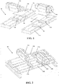
FIG. 1 is a schematic exploded view of an embodiment of a tractor assembly according to the present invention; -
FIG. 2 is a schematic assembly diagram of an embodiment of a tractor assembly according to the present invention; -
FIG. 3 is a schematic exploded view of another embodiment of a tractor assembly according to the present invention; -
FIG. 4 is a schematic assembly diagram of another embodiment of a tractor assembly according to the present invention; -
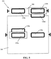
FIG. 5 is a brief top view of relative mounting positions of a tractor assembly and a car as well as a counterweight according to the present invention; and -
FIG. 6 is a schematic diagram of a connection relationship between a tractor assembly and a car as well as a counterweight according to the present invention. - Referring to
FIG. 1 and FIG. 2 , an embodiment of a tractor assembly according to the conception is shown. Thetractor assembly 100 includes: tworacks tractors traction belts traction belts elevator car 200 and anelevator counterweight 300 respectively via the twotractors tractor assembly 100, the twotractors racks - It should be known that, although the solution is described with two
racks tractors traction belts - Referring to
FIG. 1 and FIG. 2 , in a horizontally staggered arrangement manner, more specifically, one of the twotractors - In fact, as further shown in
FIG. 5 andFIG. 6 subsequently, thetractor 120a on the left is actually arranged above the elevator car, while thetractor 120b on the right is actually arranged above the elevator counterweight. As such, it can better avoid mutual interference caused by movements of the tractors, and the space is reasonably utilized. Moreover, in this case, thetractor 120a will be directly connected to the car via traction, while thetractor 120b will be directly connected to thecounterweight 300 via traction, thus avoiding the loss of force transmission caused by multiple transfer parts. - Definitely, specific spatial arrangement positions of two tractors in
FIG. 5 andFIG. 6 are only an example. Similarly, although not shown in the figures, the two tractors can also be both arranged above the elevator car, as long as they are staggered in the horizontal direction at the same time. Also similarly, the relative positions between the tractors and traction wheels can also be adjusted to adapt to different spatial requirements and transmission requirements. - Optionally, referring to
FIG. 3 and FIG. 4 , as another arrangement manner, the twotractors tractors - As another optional solution, it is possible to combine the above two arrangement manners, that is, stagger the two
tractors FIG. 3 and FIG. 4 . - Herein, it should be known that, the vertical direction and the horizontal direction described above should normally use the hoistway as a reference standard. That is, the arrangement along the vertical direction indicates staggering the multiple traction parts in an extending direction of the length of the hoistway, such that a part of the tractors is arranged higher than the other part. The arrangement along the horizontal direction indicates staggering the multiple traction parts in a direction of transecting the hoistway to extend, such that rotation axes of a part of the tractors and rotation axes of the other part of the tractors are staggered on the horizontal plane.
- The structural and connection relationships between the parts therein are specifically described in the following.
- The
racks tractors traction pulleys - In this case, the borders of the multiple mounting frames should be provided with connecting portions matched with each other, such that they can be connected into a whole.
- Definitely, it is also possible to construct the whole rack into a mounting frame and dispose multiple fixed
traction pulleys traction belts elevator car 200 and theelevator counterweight 300 respectively via thetractors traction pulleys - Moreover, a rope ratio of the
tractor assembly 100 is 1:1, thus reducing the quantity of the traction belts significantly. For example, when the traction belts are steel belts or steel wire ropes, the quantity of the steel belts or steel wire ropes can be reduced greatly. - In addition, the solution of movable traction pulleys whose rope ratio is 2:1 can also be used. Although not shown in the figures, movable traction pulleys can be disposed on the
elevator car 200 and theelevator counterweight 300 respectively, thus achieving the traction on the elevator car and the elevator counterweight. - Optionally, to enhance the installation firmness of the tractors and the racks, mounting
base plates racks tractors - Optionally, to ensure that the output torque of multiple tractors can be superimposed and coordinated well and that the delay start or the following problems can be avoided, on/off of the multiple tractors should be able to be controlled in a linked manner.
- According to another aspect of the conception, an embodiment of an elevator is further provided. Referring to
FIG. 5 andFIG. 6 , the elevator includes anelevator car 200, anelevator counterweight 300, and atractor assembly 100. Thetractor assembly 100 includes tworacks tractors traction belts traction belts elevator car 200 and theelevator counterweight 300 respectively via thetractors tractors racks tractor 120a is arranged above theelevator car 200 along the horizontal direction, while thetractor 120b is arranged above theelevator counterweight 300 along the horizontal direction. With such arrangement, on the one hand, arrangement of two tractors is implemented without making too many changes to an existing structure space; on the other hand, compared with a unit that uses a heavy load tractor, the product cost can be reduced significantly while achieving basically the same technical effect. - Optionally, as an embodiment of several arrangement spaces, the
racks - In addition, the tractor assembly has good applicability, which can be applied to a number of mounting forms such as the
elevator counterweight 300 is a lateral elevator counterweight and/or a rear elevator counterweight. - An operating process of an elevator according to an embodiment of the conception will be described below with reference to
FIG. 4 . First of all, when the elevator operates, the load that originally needs to be provided by one tractor is now provided by the twotractors tractors tractor belts elevator car 200 and theelevator counterweight 300 via traction and compression of the fixedtraction pulleys elevator counterweight 300 descends when theelevator car 200 rises; theelevator counterweight 300 rises when theelevator car 200 descends. In addition, when theelevator car 200 stops on a particular floor, the elevator car may not sink and oscillate excessively during stop and start as the tractor assembly in this embodiment has up to 8-10 steel traction belts, thus greatly improving the user's comfort of taking the elevator. - The above examples mainly describe the tractor assembly and the elevator of the present invention. Although only some implementation manners of the present invention are described, those of ordinary skill in the art should understand that the present invention can be implemented in many other forms without departing from the purport and scope thereof. Therefore, the examples and implementation manners are regarded as exemplary instead of being limitative, the present invention can cover a variety of modifications and replacements without departing from the spirit and scope of the present invention as defined by the appended claims.
Claims (13)
- A tractor assembly, comprising:a rack;multiple tractors; andmultiple traction parts connected to an elevator car and an elevator counterweight respectively via the tractors,wherein the multiple tractors are mounted on the rack respectively, and are staggered along a horizontal direction and/or along a vertical direction; the vertical direction extends along an elevator hoistway, and the horizontal direction transects the elevator hoistway to extend.
- The tractor assembly according to claim 1, wherein a part of the multiple tractors is arranged above the elevator car, and the other part of the multiple tractors is arranged above the elevator counterweight.
- The tractor assembly according to claim 1 or 2, wherein the rack is constructed as a mounting frame in which multiple fixed traction pulleys are disposed; the traction parts are connected to the elevator car and the elevator counterweight respectively via the tractors and the fixed traction pulleys; and a rope ratio of the tractor assembly particularly is 1:1.
- The tractor assembly according to any of claims 1 to 3, wherein the rack comprises multiple mounting frames in each of which a set of fixed traction pulleys is disposed respectively; the tractors each correspond to a mounting frame and a set of fixed traction pulleys; and a rope ratio of the tractor assembly particularly is 1:1.
- The tractor assembly according to claim 4, wherein borders of the multiple mounting frames are provided with connecting portions matched with each other.
- The tractor assembly according to any of claims 1 to 5, further comprising movable traction pulleys disposed on the elevator car and the elevator counterweight respectively, and a rope ratio of the tractor assembly particularly being 2:1.
- The tractor assembly according to any of claims 1 to 6, wherein the rack is provided with a mounting base plate, for providing mounting positions of the tractors.
- The tractor assembly according to any of claims 1 to 7, wherein the traction parts are steel belts or steel wire ropes.
- The tractor assembly according to any of claims 1 to 8, wherein the tractor assembly comprises two tractors.
- The tractor assembly according to any of claims 1 to 9, wherein on/off of the multiple tractors can be controlled in a linked manner.
- An elevator, comprising an elevator car, an elevator counterweight, and a tractor assembly according to any of the previous claims.
- The elevator according to claim 11, wherein the rack is mounted in the elevator hoistway or an elevator machine room.
- The elevator according to claim 11 or 12, wherein the elevator counterweight is a lateral elevator counterweight and/or a rear elevator counterweight.
Applications Claiming Priority (1)
| Application Number | Priority Date | Filing Date | Title |
|---|---|---|---|
| CN201710367977.0A CN108928716A (en) | 2017-05-23 | 2017-05-23 | Traction thermomechanical components and elevator |
Publications (1)
| Publication Number | Publication Date |
|---|---|
| EP3406558A1 true EP3406558A1 (en) | 2018-11-28 |
Family
ID=62217868
Family Applications (1)
| Application Number | Title | Priority Date | Filing Date |
|---|---|---|---|
| EP18173301.5A Withdrawn EP3406558A1 (en) | 2017-05-23 | 2018-05-18 | Machine assembly and elevator |
Country Status (3)
| Country | Link |
|---|---|
| US (1) | US20180339883A1 (en) |
| EP (1) | EP3406558A1 (en) |
| CN (1) | CN108928716A (en) |
Families Citing this family (1)
| Publication number | Priority date | Publication date | Assignee | Title |
|---|---|---|---|---|
| CN114074880A (en) * | 2020-08-12 | 2022-02-22 | 奥的斯电梯公司 | Elevator system and its support column assembly |
Citations (8)
| Publication number | Priority date | Publication date | Assignee | Title |
|---|---|---|---|---|
| US1093583A (en) * | 1912-07-29 | 1914-04-14 | Gen Elevator Company | Electric elevator system. |
| EP0565893A2 (en) * | 1992-04-15 | 1993-10-20 | C. HAUSHAHN GmbH & Co. | Drive for rope elevator |
| JPH1077171A (en) * | 1996-09-04 | 1998-03-24 | Toshiba Corp | Elevator hoisting device |
| WO2004071926A1 (en) * | 2003-02-13 | 2004-08-26 | Mitsubishi Denki Kabushiki Kaisha | Elevator equipment |
| KR20070088539A (en) * | 2007-03-26 | 2007-08-29 | 미쓰비시덴키 가부시키가이샤 | Elevator device |
| US20100181150A1 (en) * | 2007-07-20 | 2010-07-22 | Kone Corporation | Elevator and elevator arrangement |
| US20110315487A1 (en) * | 2009-03-16 | 2011-12-29 | Otis Elevator Company | Arrangement of elevator machines |
| WO2015056646A1 (en) * | 2013-10-18 | 2015-04-23 | 文男 濱田 | Elevator device |
Family Cites Families (22)
| Publication number | Priority date | Publication date | Assignee | Title |
|---|---|---|---|---|
| US646918A (en) * | 1900-01-27 | 1900-04-03 | Otis Elevator Co | Elevator. |
| US1132761A (en) * | 1908-12-17 | 1915-03-23 | Otis Elevator Co | Rope-drive elevator. |
| DE19632850C2 (en) * | 1996-08-14 | 1998-09-10 | Regina Koester | Traction sheave elevator without counterweight |
| FI109596B (en) * | 1997-01-23 | 2002-09-13 | Kone Corp | Lift and lift drive machinery |
| US6910553B1 (en) * | 1998-02-07 | 2005-06-28 | Herman Steinweg Gmbh Co. & Kg Baumaschinenfabrik | Building elevator |
| US6202793B1 (en) * | 1998-12-22 | 2001-03-20 | Richard N. Fargo | Elevator machine with counter-rotating rotors |
| EP1460022A1 (en) * | 2003-03-20 | 2004-09-22 | Inventio Ag | Drive unit for elevator |
| CN100572248C (en) * | 2003-12-09 | 2009-12-23 | 三菱电机株式会社 | Elevator device |
| CN100486882C (en) * | 2003-12-09 | 2009-05-13 | 三菱电机株式会社 | Elevator device |
| CN101891097B (en) * | 2004-12-27 | 2011-11-09 | 三菱电机株式会社 | Elevator device |
| WO2006093020A1 (en) * | 2005-03-01 | 2006-09-08 | Mitsubishi Denki Kabushiki Kaisha | Elevator device |
| KR101335496B1 (en) * | 2009-05-27 | 2013-12-02 | 오티스 엘리베이터 컴파니 | Modular arrangement of a double wrap traction elevator machine with dynamic braking |
| WO2013179423A1 (en) * | 2012-05-30 | 2013-12-05 | 三菱電機株式会社 | Hoisting machine base of elevator and elevator device |
| EP2888191A4 (en) * | 2012-10-31 | 2016-04-20 | Kone Corp | Elevator and method for modernizing an elevator |
| US20140353089A1 (en) * | 2013-05-28 | 2014-12-04 | Unitronics Parking Solutions Ltd. | Vehicle elevator system |
| EP2868613B1 (en) * | 2013-11-05 | 2019-05-15 | KONE Corporation | An elevator |
| US20150158702A1 (en) * | 2013-12-10 | 2015-06-11 | Thyssenkrupp Elevator Ag | Low-Rise Elevator |
| EP2985255B1 (en) * | 2014-08-11 | 2021-11-17 | KONE Corporation | Elevator |
| US20170362063A1 (en) * | 2014-12-31 | 2017-12-21 | Otis Elevator Company | Elevator system roping arrangement |
| CN104760870A (en) * | 2015-04-14 | 2015-07-08 | 赵忠义 | Double-host driving elevator |
| CN206126603U (en) * | 2016-07-11 | 2017-04-26 | 江门市蒙德电气股份有限有限公司 | Many host computers driven elevator |
| EP3421407A1 (en) * | 2017-06-16 | 2019-01-02 | Otis Elevator Company | Rope-climbing self propelled elevator system |
-
2017
- 2017-05-23 CN CN201710367977.0A patent/CN108928716A/en active Pending
-
2018
- 2018-05-18 EP EP18173301.5A patent/EP3406558A1/en not_active Withdrawn
- 2018-05-22 US US15/986,017 patent/US20180339883A1/en not_active Abandoned
Patent Citations (8)
| Publication number | Priority date | Publication date | Assignee | Title |
|---|---|---|---|---|
| US1093583A (en) * | 1912-07-29 | 1914-04-14 | Gen Elevator Company | Electric elevator system. |
| EP0565893A2 (en) * | 1992-04-15 | 1993-10-20 | C. HAUSHAHN GmbH & Co. | Drive for rope elevator |
| JPH1077171A (en) * | 1996-09-04 | 1998-03-24 | Toshiba Corp | Elevator hoisting device |
| WO2004071926A1 (en) * | 2003-02-13 | 2004-08-26 | Mitsubishi Denki Kabushiki Kaisha | Elevator equipment |
| KR20070088539A (en) * | 2007-03-26 | 2007-08-29 | 미쓰비시덴키 가부시키가이샤 | Elevator device |
| US20100181150A1 (en) * | 2007-07-20 | 2010-07-22 | Kone Corporation | Elevator and elevator arrangement |
| US20110315487A1 (en) * | 2009-03-16 | 2011-12-29 | Otis Elevator Company | Arrangement of elevator machines |
| WO2015056646A1 (en) * | 2013-10-18 | 2015-04-23 | 文男 濱田 | Elevator device |
Also Published As
| Publication number | Publication date |
|---|---|
| US20180339883A1 (en) | 2018-11-29 |
| CN108928716A (en) | 2018-12-04 |
Similar Documents
| Publication | Publication Date | Title |
|---|---|---|
| CN107673173B (en) | Household elevator car frame structure | |
| CN201161862Y (en) | Elevator cage | |
| US20180339883A1 (en) | Machine assembly and elevator | |
| CN104760870A (en) | Double-host driving elevator | |
| SG176932A1 (en) | Improved lifting mechanism for elevator | |
| CN106044489A (en) | Household car frame with overhang safety tongs | |
| CN201198428Y (en) | Elevator with traction machine arranged laterally | |
| CN219238951U (en) | Double-counterweight elevator structure | |
| CN205820636U (en) | Machine room rack construction | |
| CN214003749U (en) | Machine room-free elevator traction machine frame with shock absorption function | |
| CN215047860U (en) | Elevator lifting assembly and elevator system | |
| CN205855727U (en) | A kind of machine-roomless lift | |
| CN202936060U (en) | Intermediate guide and traction elevator | |
| CN204549738U (en) | A kind of arrangement structure of machine-roomless lift | |
| CN203976176U (en) | A kind of tractive force and the coaxial top traction of gravity household ladder | |
| CN109969909B (en) | Arrangement structure and method without machine room | |
| CN207539264U (en) | A kind of damping device for building hoist | |
| CN205602931U (en) | Elevator to a heavy guiding mechanism | |
| KR200443734Y1 (en) | Brake Device for Elevator Hoist | |
| CN217458388U (en) | Counterweight rear-mounted elevator structure without machine room | |
| CN112478986A (en) | Reverse-pulling double-counterweight elevator structure | |
| CN216889605U (en) | Guide shoe assembly, elevator counterweight frame using guide shoe assembly and elevator counterweight system | |
| CN217708449U (en) | Counterweight housing diversion sheave structure | |
| CN219408753U (en) | Novel car roof maintenance box | |
| CN222699781U (en) | Cargo anti-falling self-locking mechanism of elevator |
Legal Events
| Date | Code | Title | Description |
|---|---|---|---|
| PUAI | Public reference made under article 153(3) epc to a published international application that has entered the european phase |
Free format text: ORIGINAL CODE: 0009012 |
|
| STAA | Information on the status of an ep patent application or granted ep patent |
Free format text: STATUS: THE APPLICATION HAS BEEN PUBLISHED |
|
| AK | Designated contracting states |
Kind code of ref document: A1 Designated state(s): AL AT BE BG CH CY CZ DE DK EE ES FI FR GB GR HR HU IE IS IT LI LT LU LV MC MK MT NL NO PL PT RO RS SE SI SK SM TR |
|
| AX | Request for extension of the european patent |
Extension state: BA ME |
|
| RIN1 | Information on inventor provided before grant (corrected) |
Inventor name: ZHOU, CHUANYONG Inventor name: SHEN, YUNZHU Inventor name: WATSON, BENJAMIN |
|
| STAA | Information on the status of an ep patent application or granted ep patent |
Free format text: STATUS: REQUEST FOR EXAMINATION WAS MADE |
|
| 17P | Request for examination filed |
Effective date: 20190510 |
|
| RBV | Designated contracting states (corrected) |
Designated state(s): AL AT BE BG CH CY CZ DE DK EE ES FI FR GB GR HR HU IE IS IT LI LT LU LV MC MK MT NL NO PL PT RO RS SE SI SK SM TR |
|
| STAA | Information on the status of an ep patent application or granted ep patent |
Free format text: STATUS: EXAMINATION IS IN PROGRESS |
|
| 17Q | First examination report despatched |
Effective date: 20200729 |
|
| STAA | Information on the status of an ep patent application or granted ep patent |
Free format text: STATUS: THE APPLICATION IS DEEMED TO BE WITHDRAWN |
|
| 18D | Application deemed to be withdrawn |
Effective date: 20220111 |