EP3406551A1 - Lock for a fabric coiler - Google Patents
Lock for a fabric coiler Download PDFInfo
- Publication number
- EP3406551A1 EP3406551A1 EP18172584.7A EP18172584A EP3406551A1 EP 3406551 A1 EP3406551 A1 EP 3406551A1 EP 18172584 A EP18172584 A EP 18172584A EP 3406551 A1 EP3406551 A1 EP 3406551A1
- Authority
- EP
- European Patent Office
- Prior art keywords
- lever
- winding shaft
- winding
- levers
- nonwoven winder
- Prior art date
- Legal status (The legal status is an assumption and is not a legal conclusion. Google has not performed a legal analysis and makes no representation as to the accuracy of the status listed.)
- Granted
Links
- 239000004744 fabric Substances 0.000 title 1
- 238000004804 winding Methods 0.000 claims abstract description 158
- 230000000295 complement effect Effects 0.000 claims description 2
- 230000002265 prevention Effects 0.000 claims 1
- 208000027418 Wounds and injury Diseases 0.000 description 10
- 230000005540 biological transmission Effects 0.000 description 3
- 230000006378 damage Effects 0.000 description 3
- 230000000694 effects Effects 0.000 description 3
- 238000010276 construction Methods 0.000 description 2
- 230000010354 integration Effects 0.000 description 2
- 239000000853 adhesive Substances 0.000 description 1
- 230000001070 adhesive effect Effects 0.000 description 1
- 238000005452 bending Methods 0.000 description 1
- 238000009960 carding Methods 0.000 description 1
- 239000011248 coating agent Substances 0.000 description 1
- 238000000576 coating method Methods 0.000 description 1
- 238000011161 development Methods 0.000 description 1
- 230000018109 developmental process Effects 0.000 description 1
- 238000005516 engineering process Methods 0.000 description 1
- 230000002349 favourable effect Effects 0.000 description 1
- 208000014674 injury Diseases 0.000 description 1
- 239000000463 material Substances 0.000 description 1
- 239000004745 nonwoven fabric Substances 0.000 description 1
- 230000003287 optical effect Effects 0.000 description 1
- 238000000926 separation method Methods 0.000 description 1
Images


Classifications
-
- D—TEXTILES; PAPER
- D01—NATURAL OR MAN-MADE THREADS OR FIBRES; SPINNING
- D01G—PRELIMINARY TREATMENT OF FIBRES, e.g. FOR SPINNING
- D01G27/00—Lap- or sliver-winding devices, e.g. for products of cotton scutchers, jute cards, or worsted gill boxes
- D01G27/04—Lap- or sliver-winding devices, e.g. for products of cotton scutchers, jute cards, or worsted gill boxes with automatic discharge of lap-roll or the like
-
- B—PERFORMING OPERATIONS; TRANSPORTING
- B65—CONVEYING; PACKING; STORING; HANDLING THIN OR FILAMENTARY MATERIAL
- B65H—HANDLING THIN OR FILAMENTARY MATERIAL, e.g. SHEETS, WEBS, CABLES
- B65H18/00—Winding webs
- B65H18/08—Web-winding mechanisms
- B65H18/10—Mechanisms in which power is applied to web-roll spindle
-
- B—PERFORMING OPERATIONS; TRANSPORTING
- B25—HAND TOOLS; PORTABLE POWER-DRIVEN TOOLS; MANIPULATORS
- B25J—MANIPULATORS; CHAMBERS PROVIDED WITH MANIPULATION DEVICES
- B25J15/00—Gripping heads and other end effectors
- B25J15/02—Gripping heads and other end effectors servo-actuated
- B25J15/0206—Gripping heads and other end effectors servo-actuated comprising articulated grippers
- B25J15/022—Gripping heads and other end effectors servo-actuated comprising articulated grippers actuated by articulated links
-
- B—PERFORMING OPERATIONS; TRANSPORTING
- B65—CONVEYING; PACKING; STORING; HANDLING THIN OR FILAMENTARY MATERIAL
- B65H—HANDLING THIN OR FILAMENTARY MATERIAL, e.g. SHEETS, WEBS, CABLES
- B65H18/00—Winding webs
- B65H18/02—Supporting web roll
- B65H18/028—Both ends type
-
- B—PERFORMING OPERATIONS; TRANSPORTING
- B65—CONVEYING; PACKING; STORING; HANDLING THIN OR FILAMENTARY MATERIAL
- B65H—HANDLING THIN OR FILAMENTARY MATERIAL, e.g. SHEETS, WEBS, CABLES
- B65H19/00—Changing the web roll
- B65H19/22—Changing the web roll in winding mechanisms or in connection with winding operations
- B65H19/2238—The web roll being driven by a winding mechanism of the nip or tangential drive type
- B65H19/2253—The web roll being driven by a winding mechanism of the nip or tangential drive type and the roll being displaced during the winding operation
- B65H19/2261—Pope-roller
-
- B—PERFORMING OPERATIONS; TRANSPORTING
- B65—CONVEYING; PACKING; STORING; HANDLING THIN OR FILAMENTARY MATERIAL
- B65H—HANDLING THIN OR FILAMENTARY MATERIAL, e.g. SHEETS, WEBS, CABLES
- B65H19/00—Changing the web roll
- B65H19/22—Changing the web roll in winding mechanisms or in connection with winding operations
- B65H19/30—Lifting, transporting, or removing the web roll; Inserting core
- B65H19/305—Inserting core
-
- B—PERFORMING OPERATIONS; TRANSPORTING
- B65—CONVEYING; PACKING; STORING; HANDLING THIN OR FILAMENTARY MATERIAL
- B65H—HANDLING THIN OR FILAMENTARY MATERIAL, e.g. SHEETS, WEBS, CABLES
- B65H18/00—Winding webs
- B65H18/08—Web-winding mechanisms
- B65H18/14—Mechanisms in which power is applied to web roll, e.g. to effect continuous advancement of web
- B65H18/16—Mechanisms in which power is applied to web roll, e.g. to effect continuous advancement of web by friction roller
-
- B—PERFORMING OPERATIONS; TRANSPORTING
- B65—CONVEYING; PACKING; STORING; HANDLING THIN OR FILAMENTARY MATERIAL
- B65H—HANDLING THIN OR FILAMENTARY MATERIAL, e.g. SHEETS, WEBS, CABLES
- B65H2301/00—Handling processes for sheets or webs
- B65H2301/40—Type of handling process
- B65H2301/41—Winding, unwinding
- B65H2301/417—Handling or changing web rolls
- B65H2301/418—Changing web roll
- B65H2301/4182—Core or mandrel insertion, e.g. means for loading core or mandrel in winding position
- B65H2301/41822—Core or mandrel insertion, e.g. means for loading core or mandrel in winding position from above, i.e. by gravity
-
- B—PERFORMING OPERATIONS; TRANSPORTING
- B65—CONVEYING; PACKING; STORING; HANDLING THIN OR FILAMENTARY MATERIAL
- B65H—HANDLING THIN OR FILAMENTARY MATERIAL, e.g. SHEETS, WEBS, CABLES
- B65H2701/00—Handled material; Storage means
- B65H2701/10—Handled articles or webs
- B65H2701/17—Nature of material
- B65H2701/174—Textile; fibres
Definitions
- the invention relates to a lock for a nonwoven winder for securely gripping a winding shaft and a nonwoven winder equipped therewith.
- Nonwoven winder are known per se. They serve to wind a fleece, for example coming out of a carding machine, onto a winding shaft.
- empty winding shafts are automatically wound in succession. This is done by passing incoming nonwoven material around a rotating contact roll.
- An empty winding shaft which is provided with an adhesive surface and rotates in the direction opposite to the contact roller, is placed against the contact roller and, due to the adhesion effect, takes over the nonwoven from the contact roller.
- Empty winding shafts are usually housed in a magazine of the nonwoven winder. To wind an empty winding shaft, it is transferred from the magazine to a waiting position in which the winding shaft is turned on, that is set in rotation.
- the winding shaft is locked at both ends by means of a pair of pliers and is preferably transported via a Anwickelposition in the actual winding position. There, the winding shaft is taken over by a winding and Ausschubabites, solves the tong lock and is moved back towards the next, in waiting position, another winding shaft to now receive this winding shaft or to lock.
- the winding shaft located in the winding position is pressed by means of the winding and Ausschubabitess against the rotating contact roller and wound due to the friction with this located on the contact roller fleece. If the winding shaft is almost completely wound, it is brought into a Ausschubposition, and the next winding shaft is locked, turned on and transported, as described above.
- two-sided acting pliers devices are known, which are very complex in construction.
- their locking elements must be brought from two sides of the winding shaft to this, which complicates the movement path of the lock and their particular drive technology integration in the nonwoven winder.
- the object of the invention is to counteract these disadvantages.
- a device which is configured to be integrated into a nonwoven winder in such a way that the nonwoven winder is able to transfer a winding shaft from a waiting position into a winding position and / or a winding position by means of the device.
- the device has a lever arrangement. This is such that it surrounds the winding shaft from one side in a locking state such that the lever arrangement, seen in the longitudinal direction of the winding shaft, is open to one side of the winding shaft and the Levers are arranged so that a weight force of the winding shaft is prevented from introducing into the lever assembly a (release) force, which is adapted to release the lock or release.
- the lever assembly engages only on one side of the winding shaft, which allows a simple rotational movement of the lever assembly for locking and transporting the locked winding shaft.
- no further means are required due to this embodiment, which prevent loosening of the winding shaft from the device, even if the drive element, for example in the form of a pneumatic cylinder, no force is exerted in the direction of locking more because, for example, a leak is present.
- the drive element could also be switched off after the locking of the winding shaft until it is unlocked again, which helps to save energy.
- Preventing such a release force is preferably realized by directing a weight force of the winding roll by means of the lever arrangement such that a resultant force is directed in the direction of at least one pivotal mounting of the lever arrangement substantially perpendicular to a movement path of the pivot bearing in the locking point.
- the weight force is unable to generate a force or torque on the lever arrangement which acts against the locking direction of the device.
- Both devices may have a drive section. This is arranged to move the lever assembly in the direction of locking state. This promotes an automatic winding operation of the nonwoven winder.
- the lever assembly may comprise a first and a second lever arm, each at one end to a and the same part are rotatably arranged.
- the first lever arm is pivotally connected at the other end to the second lever arm.
- This connection is such that a pivoting of the first lever in the direction of locking state results in that the winding roll between the one part and the second lever is taken out safe fall and the second lever is pivoted so that a free end of the second lever and the percussiongelenkige Connection between the two levers deflects the force of the winding shaft in the direction of a pivotal mounting of the first lever in the direction substantially perpendicular to the path of movement of a rotary bearing.
- the pivotal connection between the two levers is preferably realized by means of a rotatably arranged on two levers intermediate lever. This allows an additional degree of freedom in the realization of the inventive effect of the device.
- all levers are arranged rotatable about mutually parallel axes. Ie. the movement of the levers towards each other takes place exclusively in one plane.
- This allows a particularly space-saving integration in the nonwoven winder, since laterally of this plane other parts of the nonwoven winder, such as a transport device for transporting a winding shaft from the magazine to the waiting position can be arranged without increasing the width dimension of the nonwoven winder too much.
- this is preferably pivotally connected to one of the levers. Ie. the forced by the drive portion movement of a single lever is sufficient for locking and unlocking the Winding shaft off. This allows a very simple and thus inexpensive drive mechanism.
- the driven lever is preferably the aforementioned, first lever.
- the drive section preferably has a pneumatic cylinder. This is at one end pivotally mounted on the one part and arranged so that the piston is arranged in a direction transverse to the axis of rotation of the one of the lever, so preferably the first lever, movable and is pivotally connected at its free end with this lever.
- the pneumatic solution has the advantage that the device due to its own rotation while moving the winding shaft between waiting or Anmosposition and winding position can be easily connected to a fixed in relation to the nonwoven winder energy supply here by means of compressed air.
- the second lever in the contact region with the winding shaft in the locking state may be substantially complementary to an outer contour of the winding shaft. This promotes a maximum contact surface between the second lever and winding shaft and thus the greatest possible clamping action.
- At least one lever may be present in duplicate. Both levers are arranged so that their axes of rotation coincide. Ie. they have one and the same axis of rotation. One of these two levers is arranged on a first outside of one of the other levers pointing in the direction of its axis of rotation, which is not part of the duplicate lever. The other of these two levers is accordingly arranged on one of the first outer side facing away, second outer side of this other lever.
- the double lever thus includes the other lever, transverse to the axis of rotation, a. This has the advantage that no tilting moments can occur that affect the pivot bearing of the lever and possibly could lead to damage to the pivot bearing. This serves the longevity of the device.
- a nonwoven winder is arranged according to the invention to wind a first winding roll with an incoming fleece, and to bring a second winding roll into a waiting position. He has at least one of the aforementioned devices. Each device is mounted on a conveying portion of the nonwoven winder in a waiting state so that its lever assembly is capable of clampingly gripping the second winding roll.
- the conveying section is designed to move the second winding roll clamped or locked by the device from the waiting position toward the winding position and / or winding position of the nonwoven winder.
- the nonwoven winder additionally has another of the aforementioned devices. Both devices are arranged on two opposite sides of the nonwoven winder such that in the locked state each device has a respective end of the second winding shaft clamped attacks. Ie. the winding shaft remains free of the devices according to the invention with regard to the fleece-receiving region and the section for moving the winding shaft.
- the locking elements structurally influence other components of the nonwoven winder little or not at all, so that they can be further developed in terms of their function (s) or can be designed in the usual way. This promotes integrability even in existing nonwoven winder.
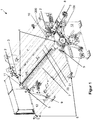
- FIG. 1 shows a nonwoven winder 1 according to an embodiment of the invention.
- the components which are immaterial to the invention are not explained further.
- the nonwoven winder 1 essentially comprises two frame walls 12, which are combined via non-designated connectors to form a frame which receives or holds all other functional elements of the nonwoven winder 1.
- the frame walls 12 have in a right-hand area a magazine 2 in which undelivered winding shafts (in this case two) are located.
- the nonwoven winder 1 comprises on each frame wall 12 a recess which defines a waiting position 3 for a winding shaft 20. Since the winding shafts are held on both sides by a respective frame wall 12, a waiting position 3 is thus realized by means of the two frame walls 12.
- the frame walls 12 thus form a holding section for a winding shaft 20 to be wound by means of the waiting position.
- the winding shaft 20 arranged therein is set in rotation by means of a clamping section 10.
- the Andrehabites 10 contacts the area of the winding shaft 20, which serves to receive fleece. Ie. not the entire winding shaft 20 is set in rotation but only here so centrally arranged thus winding section 21, the circumference forms the actual winding surface.
- a transport section 8 is provided.
- the nonwoven winder 1 has a Anwickelposition 4, which is located in a bending region, as seen along the axis of rotation of a contact roller 7 of the web unwinder 1, between the frame wall 12 and contact roller 7.
- the contact roller 7 leads in a known manner, the incoming fleece zoom to be wound on the winding shaft.
- a separating section 11 is provided.
- the nonwoven winder 1 has a winding position 5, which is realized by means of a section arranged here on the left between frame wall 12 and contact roller 7. In this position 5, the corresponding winding shaft, which has already taken up fleece in the Anwickelposition 4, finally wound.
- a movement portion 100 and a locking portion 200 are used.
- the fleece After winding the respective winding shaft, the fleece is separated by means of the separating section 11, and the wound winding shaft is moved by means of a winding and Ausschubabitess 9 in a Ausschubposition 6 of the web unwinder 1.
- FIG. 2 shows the nonwoven winder 1 with respect to its movement portion 100 in two views.
- Each here two movement sections 100 preferably comprises on both outer sides of the frame walls 12 elements which serve to move here the winding shaft 20 from the waiting or Anatomposition 3 in the Anwickelposition 4 and / or in the winding position 5.
- a belt 103 is provided by way of example, which is looped around a first, non-visible pulley and around a second belt pulley 108 of one of the movement sections 100.
- Each moving portion 100 includes a belt 103 wound around the respective pulley 108 and a second pulley 106.
- a connecting shaft 104 is provided to link the pulleys 106 of both moving portions 100 together.
- the connecting shaft 104 is freely rotatably received by both frame walls 12 by means of pivot bearings 13 in the frame walls 12.
- a motor 101 is operatively connected by means of a transmission 102 to a non-visible pulley, around which the belt 103 is looped.
- the motor 101 is thus able to transmit its rotational movement via the two belts 103 and the connecting shaft 104 also to the other, here rear side of the rear frame wall 12 and thus to the second movement section 100.
- Motor 101, gear 102 and preferably also the non-visible pulley are preferably fastened by means of a fastening element 107 on the front frame wall 12 here and thus form a drive module.
- All belts 103 may have or be acted upon by a respective belt tensioner.
- FIG. 3 is an enlarged section of the nonwoven winder 1 in the region of a movement portion 100 and the associated locking portion 200th
- the pulley 108 and the pivoting part 109 are fastened to each other by means of fastening elements 112 such as screws.
- a pneumatic cylinder 110 is attached together with a linear guide 111.
- the linear guide 111 translates a carriage 250 of the locking portion 200 from right to left and back.
- the locking portion 200 includes a pneumatic cylinder 210 which is pivotally mounted to the slide 250 with an end facing away from its piston 211.
- the free end of the piston 211 in turn is pivotally attached to one end of a cylinder lever 220, the other end is also pivotally mounted on the carriage 250.
- a connecting lever 240 is hinged at one end. At the other end, the connecting lever 240 is articulated to a locking lever 230.
- the locking lever 230 is articulated at its right-hand end to the carriage 250. Its left end carries a not visible here role, which abuts the winding shaft 20 in the state shown.
- the pneumatic cylinder 110 is able, via its piston, not shown here, to move the carriage 250 along the linear guide 111.
- the winding shaft 20 is to be moved from the waiting position 3 to the winding position 4, the likewise not visible belt 103 is moved by means of the motor 101, not shown here, so that the pulley 108 is rotated counterclockwise here. Thus, the locking portion 200 is rotated.
- the section takes over the winding shaft 20 and presses it against the contact roller 7, and the locking section 200 lets the winding shaft 20 go again.
- the pivot member 109 in the opposite direction, ie clockwise according to FIG. 4 , Turned back to take over the next, located in waiting position 3 winding shaft when the now located in winding position 5 winding shaft is almost fully wound and the web is transferred to a new winding shaft 20.
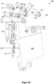
- FIG. 5 shows the locking portion 200 in four views.
- FIG. 5a shows the locking portion 200 as part of the nonwoven winder 1 with locked winding shaft 20.
- the winding shaft 20 is here by means of a storage section here in the form of a bearing sleeve 22 from the locking portion 200 used.
- FIG. 5b shows the locking portion 200 without winding shaft 20 and without front cylinder lever 220th
- the storage section 22 is freely rotatable with respect to the winding section 21 of the winding shaft 20. This makes it possible, as explained above, only turn the winding section 21.
- the locking portion 200 includes the above-described carriage 250, which also serves as a fastening element for the other elements of the locking portion 200.
- the pneumatic cylinder 210 is pivotally mounted at one end, which is remote from its piston 211, on the carriage 250 about an axis parallel to the axis of rotation or longitudinal extension of the winding shaft 20 freely rotatable. At this end are preferably also two ports 212 of the pneumatic cylinder 210 for sensors.
- the free end of the piston 211 is articulated via a connecting pin 201 at articulation points 221 here two cylinder lever 220.
- the articulation points 221 are formed at a first end of the respective cylinder lever 220. At another end, each cylinder lever 220 is articulated via a second articulation point 222 by means of a bearing pin 207 on the carriage 250. The bearing pin 207 thus forms the center of rotation of the respective lever 220.
- a connecting bolt 202 is freely rotatable or rotationally fixed on the respective cylinder lever 220.
- the connecting pin 202 extends from a cylinder lever 220 to the other.
- each have a connecting lever 240 is arranged and pivotally connected via a respective pivot point 241 and the connecting pin 202 with the cylinder levers 220, 220.
- each connecting lever 240 is pivotally articulated to the locking lever 230 at a respective articulation point 242 via a connecting pin 203.
- the locking lever 230 is also articulated at a left end here via a pivot point 231 and a bearing pin 208 on the carriage 250. Its right end here comprises a roller holder 232, on which a roller 204 is arranged freely rotatable. The axis of rotation of the roller 204 extends parallel to the axis of rotation of the winding shaft 20th
- the carriage 250 additionally has two roller holders 251, 252 holding a respective roller 205 and 206, respectively. Both rollers 205, 206 are arranged freely rotatable parallel to the roller 204 with respect to the other locking portion 200.
- FIG. 5c shows a view analog FIG. 5a in the form of a plan view of the front end of the winding shaft 20 in FIG. 5a
- FIG. 5d shows a view similar to Figure 5c, except that in FIG. 5c Front cylinder lever 220 is missing.
- a circle line shown by a dashed line indicates a movement path K1 of the connecting bolt 202 when the cylinder lever 220 is rotated by the pneumatic cylinder 210.
- the dashed circle indicates a movement path K2 of the connecting bolt 203 when the lock lever 230 is rotated.
- a circular line shown by a double dot-dashed line indicates a movement path K3 of the roller 204 when the lock lever 230 is pivoted.
- the piston 211 of the pneumatic cylinder 210 is preferably moved out. If, for example, due to a leak, the pressure in the pneumatic cylinder 210 drops, this could lead to the winding shaft 20 coming off the lock.
- the levers 220, 230, 240 and the articulation points are arranged both on the carriage 250 and on the levers 220, 240 such that a pressing of the winding shaft 20 against the roller 204 due to the weight of the winding shaft 20 causes that a resulting, introduced into the bearing pin 203 and transmitted via the lever 240 on the connecting pin 202 force substantially perpendicular to a center of the connecting pin 202 intersecting tangent T runs on the circle K1.
- the resulting angle ⁇ between the existing force line F and the tangent T is in the best case exactly 90 ° or slightly smaller. This results in that in the cylinder lever 220, no torque can be introduced, which could cause the lever 220, unfortunately, in a counterclockwise rotation in FIG.
- the locking is released releasably.
- the torque (even minus any frictional forces) is 0.
- the geometric arrangement of the levers 220, 230, 240 is thus in the locking state such that the locking acts self-locking.
- the winding shaft 20 can not easily disengage from the lock, even if the pneumatic cylinder 210 can no longer apply force in the extension direction of the piston 211.
- a separate locking section 200 belongs to each movement section 100.
- connection shaft 104 analog to the connecting shaft, which rotates the driven lever 230 together.
- Each pneumatic cylinder 110 may be replaced by any other drive element such as a worm drive electric motor.
- the worm gear could also be self-locking.
- the electric motor acts on the lever 230, for example, via a belt drive with the same rotation.
- a sensor may be provided to detect when the winding shaft 20 is in waiting position 3, in Anwickelposition 4 and / or in winding position 5.
- the sensor may include optical sensors.
- touch-sensitive sensors such as switches are conceivable, which are advantageously actuated by the respective winding shaft when they reach the respective position 3-5.
- a direct contact with the carriage 250 or lever 240 may also be provided.
- the contact surface of the respective element 250, 240 preferably has an elastic surface, which can be realized for example by means of a coating.
- the respective contact surface is preferably shaped to the outer contour of the bearing section 21 of the winding shaft 20 in order to achieve the greatest possible contact surface with the winding shaft 20.
- an electromagnetic support support may be provided on the locking portion 200.
- the carriage 111 is received on the linear guide 124 preferably guided by means of a dovetail guide or ball recirculation guide.
- the belt drives may be replaced individually or in total by any other transmission mechanism such as a chain drive.
- one of the levers 230, 240 may be arranged centrally, so that in the case preferably the levers 240, 250 and 230, 250 are paired and each individually facing away from one another, in the direction of the axis of rotation of the respective lever 230, 240 facing outer surfaces of this lever 230, 240 are arranged.
- the invention provides a simple and cost-effective way to keep a winding shaft 20 when moving from the waiting position 3 in the Anwickelposition 4 or 5 winding position safe.
Landscapes
- Engineering & Computer Science (AREA)
- Robotics (AREA)
- Mechanical Engineering (AREA)
- Textile Engineering (AREA)
- Replacement Of Web Rolls (AREA)
- Replacing, Conveying, And Pick-Finding For Filamentary Materials (AREA)
Abstract
Eine Vorrichtung (200) ist eingerichtet, in einen Vlieswickler (1) integriert zu werden, sodass dieser mittels der Vorrichtung (200) eine Wickelwelle (20) von einer Warteposition (3) in eine Anwickelposition (4) und/oder eine Wickelposition (5) überführen kann. Sie weist eine Hebelanordnung (220, 230, 240) auf, die dergestalt ist, dass sie in einem Verriegelungszustand die Wickelwelle (20) von einer Seite her derart umgreift, dass die Hebelanordnung (220, 230, 240), in Längsrichtung der Wickelwelle (20) gesehen, zu einer Seite der Wickelwelle (20) hin offen ist und die Hebel so angeordnet sind, dass eine Gewichtskraft der Wickelwelle (20) daran gehindert ist, in die Hebelanordnung (220, 230, 240) eine Kraft einzuleiten, die geeignet ist, die Verriegelung aufzuheben.A device (200) is set up to be integrated into a nonwoven winder (1) so that it can move a winding shaft (20) from a waiting position (3) into a winding position (4) and / or a winding position (5) by means of the device (200) ) can convict. It has a lever arrangement (220, 230, 240) which is such that, in a locking state, it engages around the winding shaft (20) from one side such that the lever arrangement (220, 230, 240), in the longitudinal direction of the winding shaft (FIG. 20), is open to one side of the winding shaft (20) and the levers are arranged so that a weight force of the winding shaft (20) is prevented from introducing into the lever assembly (220, 230, 240) a force that is suitable is to pick up the lock.
Ein Vlieswickler (1) ist eingerichtet, eine erste Wickelwelle (20) mit einem ankommenden Vlies zu bewickeln, und eine zweite Wickelwelle (20) in eine Warteposition (3) zu bringen. Er weist die Vorrichtung (200) auf. Diese ist an einem Beförderungsabschnitt des Vlieswicklers (1) in einem Wartezustand so angebracht, dass deren Hebelanordnung (220, 230, 240) die zweite Wickelwelle (20) klemmend greifen kann. Der Beförderungsabschnitt ist gestaltet, die geklemmte, zweite Wickelwelle (20) von der Warteposition (3) in Richtung Anwickelposition (4) und/oder Wickelposition (5) des Vlieswicklers (1) zu bewegen.

Description
Die Erfindung betrifft eine Verriegelung für einen Vlieswickler zum sicheren Ergreifen einer Wickelwelle sowie einen damit ausgestatteten Vlieswickler.The invention relates to a lock for a nonwoven winder for securely gripping a winding shaft and a nonwoven winder equipped therewith.
Vlieswickler an sich sind bekannt. Sie dienen dazu, ein beispielsweise aus einer Karde herauskommendes Vlies auf eine Wickelwelle aufzuwickeln. Dazu werden leere Wickelwellen im automatischen Wechsel nacheinander bewickelt. Dies erfolgt, indem ankommendes Vliesmaterial um eine rotierende Kontaktwalze herumgeführt wird. Eine mit einer adhäsiv wirkenden Oberfläche versehene und in zur Kontaktwalze entgegengesetzter Richtung rotierende, leere Wickelwelle wird an die Kontaktwalze angelegt und übernimmt aufgrund der Adhäsionswirkung das Vlies von der Kontaktwalze. Leere Wickelwellen sind üblicherweise in einem Magazin des Vlieswicklers untergebracht. Um eine leere Wickelwelle zu bewickeln, wird diese aus dem Magazin in eine Warteposition überführt, in der die Wickelwelle angedreht, also in Rotation versetzt wird. Dabei ist die Wickelwelle beiderends mittels einer Art Zange verriegelt und wird vorzugsweise über eine Anwickelposition in die eigentliche Wickelposition befördert. Dort wird die Wickelwelle von einem Wickel- und Ausschubabschnitt übernommen, die Zangenverriegelung löst und wird in Richtung nächste, sich in Warteposition befindlicher, anderer Wickelwelle zurückbewegt, um nunmehr diese Wickelwelle aufzunehmen bzw. zu verriegeln. Während des Bewickelns wird die sich in Wickelposition befindliche Wickelwelle mittels des Wickel- und Ausschubabschnitts gegen die rotierende Kontaktwalze gedrückt und aufgrund der Reibung mit dieser mit dem sich auf der Kontaktwalze befindlichen Vlies bewickelt. Ist die Wickelwelle nahezu vollständig bewickelt, wird sie in eine Ausschubposition gebracht, und die nächste Wickelwelle wird verriegelt, angedreht und transportiert, wie vorstehend beschrieben.Nonwoven winder are known per se. They serve to wind a fleece, for example coming out of a carding machine, onto a winding shaft. For this purpose, empty winding shafts are automatically wound in succession. This is done by passing incoming nonwoven material around a rotating contact roll. An empty winding shaft, which is provided with an adhesive surface and rotates in the direction opposite to the contact roller, is placed against the contact roller and, due to the adhesion effect, takes over the nonwoven from the contact roller. Empty winding shafts are usually housed in a magazine of the nonwoven winder. To wind an empty winding shaft, it is transferred from the magazine to a waiting position in which the winding shaft is turned on, that is set in rotation. The winding shaft is locked at both ends by means of a pair of pliers and is preferably transported via a Anwickelposition in the actual winding position. There, the winding shaft is taken over by a winding and Ausschubabschnitt, solves the tong lock and is moved back towards the next, in waiting position, another winding shaft to now receive this winding shaft or to lock. During winding, the winding shaft located in the winding position is pressed by means of the winding and Ausschubabschnitts against the rotating contact roller and wound due to the friction with this located on the contact roller fleece. If the winding shaft is almost completely wound, it is brought into a Ausschubposition, and the next winding shaft is locked, turned on and transported, as described above.
Zum Verriegeln der Wickelwelle mittels der Zange sind hinsichtlich der Rotationsachse der Wickelwelle zweiseitig wirkende Zangenvorrichtungen bekannt, die sehr aufwändig im Aufbau sind. Zudem müssen deren Verriegelungselemente von zwei Seiten der Wickelwelle an diese herangeführt werden, was den Bewegungsweg der Verriegelung und deren insbesondere antriebstechnisch Integration in den Vlieswickler verkompliziert. Abgesehen davon kann es bei Verlust der Energie bei einem eine Zange betätigenden Antriebselement dazu kommen, dass sich die Wickelwelle aufgrund ihres Gewichts aus der Verriegelung löst und sich unkontrolliert bewegt, beispielsweise fällt. Dies stellt ein hohes Verletzungsrisiko für sich in der Nähe befindliche Personen und die Gefahr dar, andere Teile beispielsweise des Vlieswicklers zu beschädigen.For locking the winding shaft by means of the pliers with respect to the axis of rotation of the winding shaft two-sided acting pliers devices are known, which are very complex in construction. In addition, their locking elements must be brought from two sides of the winding shaft to this, which complicates the movement path of the lock and their particular drive technology integration in the nonwoven winder. Apart from this, it can happen that the winding shaft due to their weight from the lock and moves uncontrollably, for example, falls in loss of energy in a forceps actuated drive element. This poses a high risk of injury to nearby persons and the danger of damaging other parts of, for example, the nonwoven winder.
Aufgabe der Erfindung ist es, diesen Nachteilen zu begegnen.The object of the invention is to counteract these disadvantages.
Diese Aufgabe wird durch den Gegenstand der Ansprüche 1 und 12 gelöst. Vorteilhafte Weiterbildungen sind in den Unteransprüchen angegeben.This object is solved by the subject matter of
Erfindungsgemäß ist eine Vorrichtung vorgesehen, die eingerichtet ist, derart in einen Vlieswickler integriert zu werden, dass der Vlieswickler in der Lage ist, mittels der Vorrichtung eine Wickelwelle von einer Warteposition vorzugsweise in eine Anwickelposition und/oder eine Wickelposition zu überführen. Die Vorrichtung weist eine Hebelanordnung auf. Diese ist dergestalt, dass sie in einem Verriegelungszustand die Wickelwelle von einer Seite her derart umgreift, dass die Hebelanordnung, in Längsrichtung der Wickelwelle gesehen, zu einer Seite der Wickelwelle hin offen ist und die Hebel so angeordnet sind, dass eine Gewichtskraft der Wickelwelle daran gehindert ist, in die Hebelanordnung eine (Löse-)Kraft einzuleiten, die geeignet ist, die Verriegelung aufzuheben bzw. zu lösen. D. h. die Hebelanordnung greift nur einseitig an der Wickelwelle an, was eine einfache Rotationsbewegung der Hebelanordnung zum Arretieren und Transportieren der verriegelten Wickelwelle ermöglicht. Zudem sind aufgrund dieser Ausgestaltung keine weiteren Mittel erforderlich, die ein Lösen der Wickelwelle aus der Vorrichtung verhindern, selbst wenn vom Antriebselement beispielsweise in Form eines Pneumatikzylinders keine Kraft in Richtung Verriegelung mehr ausgeübt wird, weil beispielsweise ein Leck vorhanden ist. Abgesehen davon könnte das Antriebselement nach erfolgtem Verriegeln der Wickelwelle bis zum Wiederentriegeln auch abgeschaltet werden, was Energie sparen hilft.According to the invention, a device is provided which is configured to be integrated into a nonwoven winder in such a way that the nonwoven winder is able to transfer a winding shaft from a waiting position into a winding position and / or a winding position by means of the device. The device has a lever arrangement. This is such that it surrounds the winding shaft from one side in a locking state such that the lever arrangement, seen in the longitudinal direction of the winding shaft, is open to one side of the winding shaft and the Levers are arranged so that a weight force of the winding shaft is prevented from introducing into the lever assembly a (release) force, which is adapted to release the lock or release. Ie. the lever assembly engages only on one side of the winding shaft, which allows a simple rotational movement of the lever assembly for locking and transporting the locked winding shaft. In addition, no further means are required due to this embodiment, which prevent loosening of the winding shaft from the device, even if the drive element, for example in the form of a pneumatic cylinder, no force is exerted in the direction of locking more because, for example, a leak is present. Apart from that, the drive element could also be switched off after the locking of the winding shaft until it is unlocked again, which helps to save energy.
Das Verhindern solch einer Lösekraft ist vorzugsweise realisiert, indem eine Gewichtskraft der Wickelrolle mittels der Hebelanordnung derart geleitet wird, dass eine resultierende Kraft in Richtung zumindest einer Drehlagerung der Hebelanordnung im Wesentlichen senkrecht zu einem Bewegungsweg der Drehlagerung im Verriegelungspunkt gerichtet ist. Dies führt dazu, dass die Gewichtskraft nicht in der Lage ist, eine Kraft bzw. ein Drehmoment an der Hebelanordnung zu erzeugen, die bzw. das gegen die Verriegelungsrichtung der Vorrichtung wirkt.Preventing such a release force is preferably realized by directing a weight force of the winding roll by means of the lever arrangement such that a resultant force is directed in the direction of at least one pivotal mounting of the lever arrangement substantially perpendicular to a movement path of the pivot bearing in the locking point. As a result, the weight force is unable to generate a force or torque on the lever arrangement which acts against the locking direction of the device.
Beide Vorrichtungen können über einen Antriebsabschnitt verfügen. Dieser ist eingerichtet, die Hebelanordnung in Richtung Verriegelungszustand zu bewegen. Dies fördert einen automatischen Wickelbetrieb des Vlieswicklers.Both devices may have a drive section. This is arranged to move the lever assembly in the direction of locking state. This promotes an automatic winding operation of the nonwoven winder.
Bei jeder der vorgenannten Vorrichtungen kann die Hebelanordnung einen ersten und einen zweiten Hebelarm umfassen, die jeweils einerends an ein und demselben Teil drehbar angeordnet sind. Der erste Hebelarm ist anderenends mit dem zweiten Hebelarm drehgelenkig verbunden. Diese Verbindung ist derart, dass ein Verschwenken des ersten Hebels in Richtung Verriegelungszustand dazu führt, dass die Wickelrolle zwischen dem einen Teil und dem zweiten Hebel herausfallsicher aufgenommen wird und der zweite Hebel derart mit verschwenkt wird, dass ein freies Ende des zweiten Hebels und die drehgelenkige Verbindung zwischen den beiden Hebeln die Kraft der Wickelwelle in Richtung einer Drehlagerung des ersten Hebels in Richtung im Wesentlichen senkrecht zum Bewegungsweg dieser einen Drehlagerung umlenkt. D. h. mit dieser mit relativ wenigen Teilen aufgebauten Konstruktion kann der erfindungsgemäße Effekt realisiert werden.In each of the aforementioned devices, the lever assembly may comprise a first and a second lever arm, each at one end to a and the same part are rotatably arranged. The first lever arm is pivotally connected at the other end to the second lever arm. This connection is such that a pivoting of the first lever in the direction of locking state results in that the winding roll between the one part and the second lever is taken out safe fall and the second lever is pivoted so that a free end of the second lever and the drehgelenkige Connection between the two levers deflects the force of the winding shaft in the direction of a pivotal mounting of the first lever in the direction substantially perpendicular to the path of movement of a rotary bearing. Ie. With this constructed with relatively few parts construction, the effect of the invention can be realized.
Die drehgelenkige Verbindung zwischen den beiden Hebeln ist vorzugsweise mittels eines drehbar an beiden Hebeln angeordneten Zwischenhebels realisiert. Dies ermöglicht einen zusätzlichen Freiheitsgrad in der Realisierung der erfindungsgemäßen Wirkung der Vorrichtung.The pivotal connection between the two levers is preferably realized by means of a rotatably arranged on two levers intermediate lever. This allows an additional degree of freedom in the realization of the inventive effect of the device.
Vorzugsweise alle Hebel(arme) sind um zueinander parallele Achsen rotierbar angeordnet. D. h. die Bewegung der Hebel zueinander erfolgt ausschließlich in einer Ebene. Dies ermöglicht eine besonders platzsparende Integration in den Vlieswickler, da seitlich dieser Ebene andere Teile des Vlieswicklers wie beispielsweise eine Transportvorrichtung zum Transportieren einer Wickelwelle vom Magazin in die Warteposition angeordnet werden können, ohne die Breitenabmessung des Vlieswicklers zu stark zu vergrößern.Preferably, all levers (arms) are arranged rotatable about mutually parallel axes. Ie. the movement of the levers towards each other takes place exclusively in one plane. This allows a particularly space-saving integration in the nonwoven winder, since laterally of this plane other parts of the nonwoven winder, such as a transport device for transporting a winding shaft from the magazine to the waiting position can be arranged without increasing the width dimension of the nonwoven winder too much.
Im Falle des Antriebsabschnitts ist dieser vorzugsweise mit einem der Hebel schwenkwirkverbunden. D. h. die mittels des Antriebsabschnitts erzwungene Bewegung eines einzigen Hebels reicht zum Ver- und Entriegeln der Wickelwelle aus. Dies ermöglicht einen sehr einfach aufgebauten und damit kostengünstigen Antriebsmechanismus.In the case of the drive section, this is preferably pivotally connected to one of the levers. Ie. the forced by the drive portion movement of a single lever is sufficient for locking and unlocking the Winding shaft off. This allows a very simple and thus inexpensive drive mechanism.
Der angetriebene Hebel ist dabei bevorzugt der vorgenannte, erste Hebel.The driven lever is preferably the aforementioned, first lever.
Bei den beiden letztgenannten Varianten weist der Antriebsabschnitt vorzugsweise einen Pneumatikzylinder auf. Dieser ist einerends an dem einen Teil drehgelenkig angebracht und so angeordnet, dass dessen Kolben in eine Richtung quer zur Rotationsachse des einen der Hebel, also vorzugsweise des ersten Hebels, bewegbar angeordnet ist und an seinem freien Ende mit diesem Hebel drehgelenkig verbunden ist. Die pneumatische Lösung hat den Vorteil, dass die Vorrichtung aufgrund der eigenen Rotation während des Bewegens der Wickelwelle zwischen Warte- bzw. Andrehposition und Wickelposition einfach an eine in Bezug auf den Vlieswickler feststehende Energieversorgung hier mittels Druckluft angeschlossen werden kann.In the latter two variants, the drive section preferably has a pneumatic cylinder. This is at one end pivotally mounted on the one part and arranged so that the piston is arranged in a direction transverse to the axis of rotation of the one of the lever, so preferably the first lever, movable and is pivotally connected at its free end with this lever. The pneumatic solution has the advantage that the device due to its own rotation while moving the winding shaft between waiting or Andrehposition and winding position can be easily connected to a fixed in relation to the nonwoven winder energy supply here by means of compressed air.
Bei jeder der mit zumindest zwei Hebeln ausgestatteten Vorrichtungen kann der zweite Hebel im Kontaktbereich mit der Wickelwelle im Verriegelungszustand im Wesentlichen komplementär zu einer Außenkontur der Wickelwelle ausgebildet sein. Dies fördert eine maximale Berührungsfläche zwischen zweitem Hebel und Wickelwelle und damit eine größtmögliche Klemmwirkung.In each of the devices equipped with at least two levers, the second lever in the contact region with the winding shaft in the locking state may be substantially complementary to an outer contour of the winding shaft. This promotes a maximum contact surface between the second lever and winding shaft and thus the greatest possible clamping action.
Bei jeder der vorgenannten Vorrichtungen kann zumindest ein Hebel doppelt vorhanden sein. Beide Hebel sind dabei so angeordnet, dass ihre Rotationsachsen übereinstimmen. D. h. sie haben ein und dieselbe Rotationsachse. Einer dieser zwei Hebel ist an einer in Richtung seiner Rotationsachse weisenden ersten Außenseite eines der anderen Hebel angeordnet, der nicht Bestandteil des doppelt vorhandenen Hebels ist. Der andere dieser zwei Hebel ist dementsprechend an einer der ersten Außenseite gegenüberliegenden, abgewandten, zweiten Außenseite dieses anderen Hebels angeordnet ist. Der doppelt vorhandene Hebel schließt somit den anderen Hebel, quer zur Rotationsachse, ein. Dies hat den Vorteil, dass keine Kippmomente entstehen können, die die Drehlagerung der Hebel beeinträchtigen und gegebenenfalls zu Beschädigungen an der Drehlagerung führen könnten. Dies dient der Langlebigkeit der Vorrichtung.In each of the aforementioned devices, at least one lever may be present in duplicate. Both levers are arranged so that their axes of rotation coincide. Ie. they have one and the same axis of rotation. One of these two levers is arranged on a first outside of one of the other levers pointing in the direction of its axis of rotation, which is not part of the duplicate lever. The other of these two levers is accordingly arranged on one of the first outer side facing away, second outer side of this other lever. The double lever thus includes the other lever, transverse to the axis of rotation, a. This has the advantage that no tilting moments can occur that affect the pivot bearing of the lever and possibly could lead to damage to the pivot bearing. This serves the longevity of the device.
Ein Vlieswickler ist erfindungsgemäß eingerichtet, eine erste Wickelrolle mit einem ankommenden Vlies zu bewickeln, und eine zweite Wickelrolle in eine Warteposition zu bringen. Er weist zumindest eine der vorgenannten Vorrichtungen auf. Jede Vorrichtung ist an einem Beförderungsabschnitt des Vlieswicklers in einem Wartezustand so angebracht, dass deren Hebelanordnung in der Lage ist, die zweite Wickelrolle klemmend zu greifen. Der Beförderungsabschnitt wiederum ist gestaltet, die mittels der Vorrichtung geklemmte bzw. verriegelte, zweite Wickelrolle von der Warteposition in Richtung Anwickelposition und/oder Wickelposition des Vlieswicklers zu bewegen. Damit ist ein sicheres Bewegen der Wickelwelle von der Warteposition in Anwickelposition und davon weg in Richtung Wickelposition möglich, in der der Vlieswickler in der Lage ist, die zweite Wickelrolle mittels einer Kontaktwalze des Vlieswicklers zu bewickeln. Ferner ermöglicht die funktionelle Trennung zwischen Verriegeln und Bewegen der jeweiligen Wickelwelle das Optimieren des jeweiligen Mechanismus' auf seine Funktion hin.A nonwoven winder is arranged according to the invention to wind a first winding roll with an incoming fleece, and to bring a second winding roll into a waiting position. He has at least one of the aforementioned devices. Each device is mounted on a conveying portion of the nonwoven winder in a waiting state so that its lever assembly is capable of clampingly gripping the second winding roll. The conveying section, in turn, is designed to move the second winding roll clamped or locked by the device from the waiting position toward the winding position and / or winding position of the nonwoven winder. For a safe movement of the winding shaft from the waiting position in Anwickelposition and away in the direction of winding position is possible in which the nonwoven winder is able to wind the second winding roll by means of a contact roller of the nonwoven winder. Furthermore, the functional separation between locking and moving the respective winding shaft makes it possible to optimize the respective mechanism for its function.
Vorzugsweise weist der Vlieswickler zusätzlich eine andere der vorgenannten Vorrichtungen auf. Beide Vorrichtungen sind an zwei einander gegenüberliegenden Seiten des Vlieswicklers so angeordnet, dass im Verriegelungszustand jede Vorrichtung ein jeweiliges Ende der zweiten Wickelwelle klemmend greift. D. h. die Wickelwelle bleibt hinsichtlich des vliesaufnehmenden Bereichs und des Abschnitts zum Bewegen der Wickelwelle frei von den erfindungsgemäßen Vorrichtungen. Dadurch beeinflussen die Verriegelungselemente andere Bestandteile des Vlieswicklers konstruktiv wenig oder gar nicht, sodass diese hinsichtlich ihrer Funktion(en) weiterentwickelt werden können oder in üblicher Weise ausgestaltet sein können. Dies fördert die Integrierbarkeit auch in bestehende Vlieswickler.Preferably, the nonwoven winder additionally has another of the aforementioned devices. Both devices are arranged on two opposite sides of the nonwoven winder such that in the locked state each device has a respective end of the second winding shaft clamped attacks. Ie. the winding shaft remains free of the devices according to the invention with regard to the fleece-receiving region and the section for moving the winding shaft. As a result, the locking elements structurally influence other components of the nonwoven winder little or not at all, so that they can be further developed in terms of their function (s) or can be designed in the usual way. This promotes integrability even in existing nonwoven winder.
Weitere Merkmale und Vorteile der Erfindung ergeben sich aus der nachfolgenden Beschreibung bevorzugter Ausführungsformen. Es zeigen:
Figur 1- einen Vlieswickler gemäß einer Ausführungsform der Erfindung,
Figur 2- den
Vlieswickler von Figur 1 hinsichtlich dessen Bewegungsabschnitts, Figur 3- ein vergrößerter
Ausschnitt von Figur 2 , Figur 4- eine zu
Figur 3 ähnliche Ansicht des Vlieswicklers, wenn sich die Wickelwelle in Anwickelposition befindet, und Figur 5- den Verriegelungsabschnitt des
Vlieswicklers von Figur 1 im Verriegelungszustand in vier Ansichten.
- FIG. 1
- a nonwoven winder according to an embodiment of the invention,
- FIG. 2
- the nonwoven winder from
FIG. 1 with regard to its movement section, - FIG. 3
- an enlarged section of
FIG. 2 . - FIG. 4
- one too
FIG. 3 similar view of the nonwoven winder when the winding shaft is in Anwickelposition, and - FIG. 5
- the locking portion of the nonwoven winder of
FIG. 1 in lock state in four views.
Der Vlieswickler 1 umfasst im Wesentlichen zwei Gestellwände 12, die über nicht bezeichnete Verbinder zu einem Gestell zusammengefasst sind, das alle anderen Funktionselemente des Vlieswicklers 1 aufnimmt bzw. hält.The
Die Gestellwände 12 weisen in einem rechten Bereich ein Magazin 2 auf, in dem sich nicht bezeichnete Wickelwellen (hier: zwei) befinden.The
Weiterhin umfasst der Vlieswickler 1 an jeder Gestellwand 12 eine Ausnehmung, die eine Warteposition 3 für eine Wickelwelle 20 definiert. Da die Wickelwellen beidseitig von einer jeweiligen Gestellwand 12 gehalten werden, wird somit eine Warteposition 3 mittels der beiden Gestellwände 12 realisiert. Die Gestellwände 12 bilden mittels der Warteposition mithin einen Halteabschnitt für eine zu bewickelnde Wickelwelle 20.Furthermore, the
In der Warteposition 3 wird die darin angeordnete Wickelwelle 20 mittels eines Andrehabschnitts 10 in Rotation versetzt. Der Andrehabschnitt 10 kontaktiert dabei den Bereich der Wickelwelle 20, der der Aufnahme von Vlies dient. D. h. nicht die gesamte Wickelwelle 20 wird in Rotation versetzt sondern nur deren hier mittig angeordneter somit Wickelabschnitt 21, der umfangsseitig die eigentliche Wickelfläche bildet.In the waiting
Um eine Wickelwelle vom Magazin 2 in die Warteposition 3 zu überführen, ist ein Transportabschnitt 8 vorgesehen.In order to transfer a winding shaft from the
Ferner weist der Vlieswickler 1 eine Anwickelposition 4 auf, die sich in einem Knickbereich, gesehen entlang der Rotationsachse einer Kontaktwalze 7 des Vlieswicklers 1, zwischen Gestellwand 12 und Kontaktwalze 7 befindet. Die Kontaktwalze 7 führt in bekannter Weise das hereinkommende Vlies an die zu bewickelnde Wickelwelle heran.Furthermore, the
Zum automatischen Wechseln des Vlieses von einer Wickelwelle auf die nächste ist ein Trennabschnitt 11 vorgesehen.For automatically changing the nonwoven fabric from one winding shaft to the next, a separating
Ferner weist der Vlieswickler 1 eine Wickelposition 5 auf, die mittels eines hier links angeordneten Abschnitts zwischen Gestellwand 12 und Kontaktwalze 7 realisiert ist. In dieser Position 5 wird die entsprechende Wickelwelle, die bereits Vlies in der Anwickelposition 4 aufgenommen hat, endgültig bewickelt.Furthermore, the
Zum Transportieren hier der Wickelwelle 20 von der Warteposition 3 über die Anwickelposition 4 zur Wickelposition 5 werden ein Bewegungsabschnitt 100 und ein Verriegelungsabschnitt 200 genutzt.For transporting here the winding
Nach dem Bewickeln der jeweiligen Wickelwelle wird das Vlies mittels des Trennabschnitts 11 getrennt, und die bewickelte Wickelwelle wird mittels eines Wickel- und Ausschubabschnitts 9 in eine Ausschubposition 6 des Vlieswicklers 1 bewegt.After winding the respective winding shaft, the fleece is separated by means of the separating
Jeder hier zweier Bewegungsabschnitte 100 umfasst vorzugsweise an beiden Außenseiten der Gestellwände 12 Elemente, die dem Bewegen hier der Wickelwelle 20 von der Warte- bzw. Andrehposition 3 in die Anwickelposition 4 und/oder in die Wickelposition 5 dienen.Each here two
Für beide Bewegungsabschnitte 100 ist beispielhaft ein Riemen 103 vorgesehen, der um eine erste, nicht sichtbare Riemenscheibe und um eine zweite Riemenscheibe 108 eines der Bewegungsabschnitte 100 geschlungen ist.For both
Jeder Bewegungsabschnitt 100 umfasst einen Riemen 103, der um die jeweilige Riemenscheibe 108 und eine zweite Riemenscheibe 106 geschlungen ist. Eine Verbindungswelle 104 ist vorgesehen, die Riemenscheiben 106 beider Bewegungsabschnitte 100 miteinander bewegungszuverbinden. Mittels Rotierens der jeweiligen Riemenscheibe 108 wird ein zum jeweiligen Bewegungsabschnitt 100 gehörendes Schwenkteil 109 mitrotiert.Each moving
Die Verbindungswelle 104 ist durch beide Gestellwände 12 hindurchgehend mittels Drehlagern 13 in den Gestellwänden 12 frei rotierbar aufgenommen.The connecting
Ein Motor 101 ist mittels eines Getriebes 102 mit einer nicht sichtbaren Riemenscheibe wirkverbunden, um die der Riemen 103 geschlungen ist. Der Motor 101 ist damit in der Lage, seine Drehbewegung über die zwei Riemen 103 und die Verbindungswelle 104 auch auf die andere, hier Rückseite der hinteren Gestellwand 12 und damit auf den zweiten Bewegungsabschnitt 100 zu übertragen.A
Motor 101, Getriebe 102 und vorzugsweise auch die nicht sichtbare Riemenscheibe sind bevorzugt mittels eines Befestigungselements 107 an der hier vorderen Gestellwand 12 befestigt und bilden mithin ein Antriebsmodul.
Alle Riemen 103 können über einen jeweiligen Riemenspanner verfügen bzw. von einem solchen beaufschlagt sein.All
Im gezeigten Beispiel sind die Riemenscheibe 108 und das Schwenkteil 109 mittels Befestigungselementen 112 wie Schrauben aneinander befestigt. An dem Schwenkteil 109 ist ein Pneumatikzylinder 110 nebst einer Linearführung 111 befestigt. Die Linearführung 111 führt einen Schlitten 250 des Verriegelungsabschnitts 200 translatorisch von rechts nach links und zurück.In the example shown, the
Der Verriegelungsabschnitt 200 umfasst einen Pneumatikzylinder 210, der mit einem seinem Kolben 211 abgewandten Ende an dem Schlitten 250 drehgelenkig befestigt ist. Das freie Ende des Kolbens 211 wiederum ist drehgelenkig an einem Ende eines Zylinderhebels 220 befestigt, der anderenends ebenfalls drehgelenkig am Schlitten 250 befestigt ist.The locking
In einem mittigen Bereich ist am Zylinderhebel 220 ein Verbindungshebel 240 einerends angelenkt. Anderenends ist der Verbindungshebel 240 an einem Verrieglungshebel 230 angelenkt.In a central region of the
Der Verriegelungshebel 230 ist an seinem hier rechten Ende an dem Schlitten 250 angelenkt. Sein linkes Ende trägt eine hier nicht sichtbare Rolle, die im gezeigten Zustand an der Wickelwelle 20 anliegt.The locking
Mittels Herausfahrens des Kolbens 211 ist der Pneumatikzylinder 210 in der Lage, den Verriegelungshebel 230 mit seinem linken Ende weiter in Richtung Wickelwelle 20 zu bewegen, sodass diese zwischen dem Verriegelungshebel 230 und dem Schlitten 250 festgehalten wird.By moving out of the
Der Pneumatikzylinder 110 ist über seinen hier nicht dargestellten Kolben in der Lage, den Schlitten 250 entlang der Linearführung 111 zu bewegen.The
Soll die Wickelwelle 20 von der Warteposition 3 in die Anwickelposition 4 bewegt werden, wird mittels des hier nicht dargestellten Motors 101 der ebenfalls nicht sichtbare Riemen 103 so bewegt, dass die Riemenscheibe 108 hier entgegen dem Uhrzeigersinn rotiert wird. Damit wird der Verriegelungsabschnitt 200 mitrotiert.If the winding
Dabei wird der Schlitten 250 in
In der Anwickelposition 4 wird mittels bekannten Reibeschlusses zwischen Wickelwelle 20 und Kontaktwalze 7 das Vlies von der Kontaktwalze 7 auf die Wickelwelle 20 übertragen und damit die Wickelwelle 20 angewickelt.In the
Ist die Wickelwelle 20 angewickelt, wird das Schwenkteil 109 gemäß Figur 4 weiter entgegen dem Uhrzeigersinn in Richtung Wickelposition 5 gedreht. Dabei wird im Rahmen der Linearführung 111 nunmehr darauf geachtet, dass die Wickelwelle 20 vorzugsweise ständig in Kontakt mit der Kontaktwalze 7 steht.If the winding
Befindet sich die Wickelwelle 20 in der Wickelposition 5, übernimmt der Abschnitt die Wickelwelle 20 und drückt sie an die Kontaktwalze 7, und der Verriegelungsabschnitt 200 lässt die Wickelwelle 20 wieder los. Daraufhin wird das Schwenkteil 109 in die entgegengesetzte Richtung, also im Uhrzeigersinn gemäß
Der Lagerungsabschnitt 22 ist in Bezug auf den Wickelabschnitt 21 der Wickelwelle 20 frei rotierbar angeordnet. Damit ist es möglich, wie vorstehend erläutert, nur den Wickelabschnitt 21 anzudrehen.The
Der Verriegelungsabschnitt 200 umfasst den vorstehend erläuterten Schlitten 250, der zugleich als Befestigungselement für die sonstigen Elemente des Verriegelungsabschnitts 200 dient.The locking
Der Pneumatikzylinder 210 ist mit einem Ende, das von seinem Kolben 211 entfernt ist, drehgelenkig am Schlitten 250 um eine Achse parallel zur Rotationsachse bzw. Längserstreckung der Wickelwelle 20 frei rotierbar befestigt. An diesem Ende befinden sich vorzugsweise auch zwei Anschlüsse 212 des Pneumatikzylinders 210 für Sensoren. Das freie Ende des Kolbens 211 ist über einen Verbindungsbolzen 201 an Anlenkstellen 221 hier zweier Zylinderhebel 220 angelenkt.The
Die Anlenkstellen 221 sind an einem ersten Ende des jeweiligen Zylinderhebels 220 ausgebildet. An einem anderen Ende ist jeder Zylinderhebel 220 über eine zweite Anlenkstelle 222 vermittels eines Lagerbolzens 207 am Schlitten 250 angelenkt. Der Lagerbolzen 207 bildet somit den Rotationsmittelpunkt des jeweiligen Hebels 220.The articulation points 221 are formed at a first end of the
In einem Bereich zwischen beiden Anlenkstellen 221, 222 ist am jeweiligen Zylinderhebel 220 ein Verbindungsbolzen 202 frei rotierbar oder drehfest eingesetzt. Der Verbindungsbolzen 202 erstreckt sich dabei von einem Zylinderhebel 220 zum anderen.In a region between the two
An den einander zugewandten Innenseiten der Zylinderhebel 220 ist jeweils ein Verbindungshebel 240 angeordnet und über eine jeweilige Anlenkstelle 241 und den Verbindungsbolzen 202 drehgelenkig mit den Zylinderhebeln 220, 220 verbunden.At the mutually facing inner sides of the
An seinem anderen Ende ist jeder Verbindungshebel 240 an einer jeweiligen Anlenkstelle 242 über einen Verbindungsbolzen 203 drehgelenkig nunmehr an dem Verriegelungshebel 230 angelenkt. Der Verriegelungshebel 230 ist an einem hier linken Ende über eine Anlenkstelle 231 und einen Lagerbolzen 208 ebenfalls am Schlitten 250 angelenkt. Sein hier rechtes Ende umfasst eine Rollenhalterung 232, an der eine Rolle 204 frei rotierbar angeordnet ist. Die Rotationsachse der Rolle 204 verläuft dabei parallel zur Rotationsachse der Wickelwelle 20.At its other end, each connecting
Der Schlitten 250 verfügt zusätzlich über zwei Rollenhalterungen 251, 252, die eine jeweilige Rolle 205 bzw. 206 halten. Beide Rollen 205, 206 sind parallel zur Rolle 204 frei rotierbar in Bezug auf den sonstigen Verriegelungsabschnitt 200 angeordnet.The
In einem unteren Bereich des Schlitten 250 ist dessen Führungsausnehmung 253 zum translatorischen Führen entlang der Linearführung 111 vorgesehen bzw. ausgebildet.In a lower region of the
Das Vorsehen jeweils zweier Hebel 220, 220 bzw. 240, 240 dient dem Zweck, den Verriegelungshebel 230 beidseitig erfassen zu können. Dadurch können keine Dreh- oder Kippmomente entstehen, die eine Beschädigung der Lagerung der Verbindungsbolzen 201 - 203 hervorrufen könnten.The provision of two
Eine mittels einer Strichpunktlinie dargestellte Kreislinie kennzeichnet einen Bewegungsweg K1 des Verbindungsbolzens 202, wenn der Zylinderhebel 220 mittels des Pneumatikzylinders 210 in Rotation versetzt bzw. verschwenkt wird.A circle line shown by a dashed line indicates a movement path K1 of the connecting
Die gestrichelte Kreislinie kennzeichnet einen Bewegungsweg K2 des Verbindungsbolzens 203, wenn der Verriegelungshebel 230 in Rotation versetzt bzw. verschwenkt wird.The dashed circle indicates a movement path K2 of the connecting
Eine mittels einer Doppelpunkt-Strich-Linie dargestellte Kreislinie kennzeichnet einen Bewegungsweg K3 der Rolle 204, wenn der Verriegelungshebel 230 verschwenkt bzw. in Rotation versetzt wird.A circular line shown by a double dot-dashed line indicates a movement path K3 of the
Um die Wickelwelle 20 zu verriegeln, wird der Kolben 211 des Pneumatikzylinders 210 vorzugsweise herausgefahren. Fällt nun beispielsweise aufgrund eines Lecks der Druck im Pneumatikzylinder 210 ab, könnte dies dazu führen, dass sich die Wickelwelle 20 aus der Verriegelung löst.In order to lock the winding
Um dies zu verhindern, sind die Hebel 220, 230, 240 und die Anlenkstellen sowohl am Schlitten 250 als auch an den Hebeln 220, 240 so angeordnet, dass ein Drücken der Wickelwelle 20 gegen die Rolle 204 aufgrund der Gewichtskraft der Wickelwelle 20 dazu führt, dass eine resultierende, in den Lagerbolzen 203 eingeleitete und über den Hebel 240 auf den Verbindungsbolzen 202 übertragene Kraft im Wesentlichen senkrecht zu einer den Mittelpunkt des Verbindungsbolzens 202 schneidende Tangente T an der Kreislinie K1 verläuft. Der resultierende Winkel α zwischen der so existierenden Kraftlinie F und der Tangente T ist im günstigsten Fall exakt 90° oder geringfügig kleiner. Dies führt dazu, dass in den Zylinderhebel 220 kein Drehmoment eingeleitet werden kann, das dazu führen könnte, dass der Hebel 220 unglücklicherweise in eine Rotation entgegen dem Uhrzeigersinn in
Beispielhaft gehört zu jedem Bewegungsabschnitt 100 ein eigener Verriegelungsabschnitt 200.By way of example, a
Die Erfindung ist nicht auf die vorbeschriebenen Ausführungen beschränkt.The invention is not limited to the above-described embodiments.
Gibt es zwei Verriegelungsabschnitte 200, können diese über eine zur Verbindungswelle 104 analoge Verbindungswelle verfügen, die die angetriebenen Hebel 230 miteinander rotationsverbindet.If there are two locking
Jeder Pneumatikzylinder 110 kann durch jedwedes andere Antriebselement wie einen Elektromotor mit Schneckentrieb ersetzt sein. In dem Fall könnte auch das Schneckengetriebe selbsthemmend ausgebildet sein. Oder aber der Elektromotor wirkt beispielsweise über einen Riementrieb gleich rotierend auf den Hebel 230.Each
Zudem kann eine Sensorik vorgesehen sein, um zu detektieren, wenn sich die Wickelwelle 20 in Warteposition 3, in Anwickelposition 4 und/oder in Wickelposition 5 befindet. Die Sensorik kann dabei optische Sensoren umfassen. Alternativ sind auch berührungssensitive Sensoren wie Schalter denkbar, die vorteilhafterweise von der jeweiligen Wickelwelle betätigt werden, wenn sie die jeweilige Position 3 - 5 erreichen.In addition, a sensor may be provided to detect when the winding
Anstelle zumindest einer der Rollen 204 - 206 kann auch ein direktes Anliegen am Schlitten 250 bzw. Hebel 240 vorgesehen sein. In dem Fall weist die Kontaktfläche des jeweiligen Elements 250, 240 vorzugsweise eine elastische Oberfläche auf, die beispielsweise mittels einer Beschichtung realisiert sein kann. In dem Fall ist die jeweilige Kontaktfläche vorzugsweise zur Außenkontur des Lagerabschnitts 21 der Wickelwelle 20 geformt, um eine größtmögliche Kontaktfläche mit der Wickelwelle 20 zu erreichen.Instead of at least one of the rollers 204-206, a direct contact with the
Zudem kann am Verriegelungsabschnitt 200 auch eine elektromagnetische Tragunterstützung vorgesehen sein.In addition, an electromagnetic support support may be provided on the locking
Der Schlitten 111 ist an der Linearführung 124 vorzugsweise mittels einer Schwalbenschwanzführung oder auch Kugelumlaufführung geführt aufgenommen.The
Die Riementriebe können einzeln oder insgesamt durch jedweden anderen Getriebemechanismus wie einen Kettentrieb ersetzt sein.The belt drives may be replaced individually or in total by any other transmission mechanism such as a chain drive.
Anstelle des Hebels 240 kann auch einer der Hebel 230, 240 mittig angeordnet sein, sodass in dem Fall vorzugsweise die Hebel 240, 250 bzw. 230, 250 paarig vorhanden sind und jeweils einzeln an einer der einander abgewandten, in Richtung der Rotationsachse des jeweiligen Hebels 230, 240 weisenden Außenflächen dieses Hebels 230, 240 angeordnet sind.Instead of the
Im Ergebnis schafft die Erfindung eine einfache und kostengünstig zu realisierende Möglichkeit, eine Wickelwelle 20 beim Bewegen von der Warteposition 3 in die Anwickelposition 4 oder Wickelposition 5 sicher zu halten.As a result, the invention provides a simple and cost-effective way to keep a winding
- 11
- VlieswicklerFleece roller
- 22
- Magazinmagazine
- 33
- Wartepositionwaiting position
- 44
- Anwickelpositionwinding start
- 55
- Wickelpositionwinding position
- 66
- Ausschubpositioneject
- 77
- Kontaktwalzecontact roller
- 88th
- Transportabschnitttransport section
- 99
- Wickel- und AusschubabschnittWinding and Ausschubabschnitt
- 1010
- AndrehabschnittAndrehabschnitt
- 1111
- Trennabschnittseparating section
- 1212
- Gestellwandframe wall
- 1313
- Drehlagerpivot bearing
- 2020
- Wickelwellewinding shaft
- 2121
- Wickelabschnittwinding section
- 2222
- Lagerhülsebearing sleeve
- 100100
- Bewegungsabschnittmovement section
- 101101
- Motorengine
- 102102
- Getriebetransmission
- 103103
- Riemenbelt
- 104104
- Verbindungswelleconnecting shaft
- 106106
- Riemenscheibepulley
- 107107
- Befestigungselementfastener
- 108108
- Riemenscheibepulley
- 109109
- Schwenkteilpivoting part
- 110110
- Pneumatikzylinderpneumatic cylinder
- 111111
- Linearführunglinear guide
- 112112
- Befestigungselementfastener
- 200200
- Verriegelungsabschnittlocking section
- 201 - 203201-203
- Verbindungsbolzenconnecting bolts
- 204 - 206204-206
- Rollerole
- 207, 208207, 208
- Lagerbolzenbearing bolt
- 210210
- Pneumatikzylinderpneumatic cylinder
- 211211
- Kolbenpiston
- 212212
- Anschlussconnection
- 220220
- Zylinderhebelcylinder lever
- 221,222221.222
- Anlenkstellearticulation
- 230230
- Verriegelungshebellocking lever
- 231231
- Anlenkstellearticulation
- 232232
- Rollenhalterungroll holder
- 240240
- Verbindungshebelconnecting lever
- 241, 242241, 242
- Anlenkstellearticulation
- 250250
- Schlittencarriage
- 251, 252251, 252
- Rollenhalterungroll holder
- 253253
- Führungsabschnittguide section
- FF
- Kraftliniepower line
- K1 - K3K1 - K3
- Bewegungskreismovement circle
- TT
- Tangentetangent
- αα
- Winkelangle
Claims (13)
eingerichtet, derart in einen Vlieswickler (1) integriert zu werden, dass der Vlieswickler (1) in der Lage ist, mittels der Vorrichtung (200) eine Wickelwelle (20) von einer Warteposition (3) in eine Anwickelposition (4) und/oder eine Wickelposition (5) zu überführen, und
arranged to be integrated into a nonwoven winder (1) in such a way that the nonwoven winder (1) is able to move a winding shaft (20) from a waiting position (3) into a winding position (4) and / or by means of the device (200) to transfer a winding position (5), and
Priority Applications (1)
| Application Number | Priority Date | Filing Date | Title |
|---|---|---|---|
| PL18172584T PL3406551T3 (en) | 2017-05-24 | 2018-05-16 | Locking device for a non-woven winder |
Applications Claiming Priority (1)
| Application Number | Priority Date | Filing Date | Title |
|---|---|---|---|
| DE102017111428.9A DE102017111428B4 (en) | 2017-05-24 | 2017-05-24 | Lock for a fleece winder |
Publications (2)
| Publication Number | Publication Date |
|---|---|
| EP3406551A1 true EP3406551A1 (en) | 2018-11-28 |
| EP3406551B1 EP3406551B1 (en) | 2021-04-28 |
Family
ID=62196363
Family Applications (1)
| Application Number | Title | Priority Date | Filing Date |
|---|---|---|---|
| EP18172584.7A Active EP3406551B1 (en) | 2017-05-24 | 2018-05-16 | Locking device for a non-woven winder |
Country Status (4)
| Country | Link |
|---|---|
| EP (1) | EP3406551B1 (en) |
| CN (1) | CN108946252B (en) |
| DE (1) | DE102017111428B4 (en) |
| PL (1) | PL3406551T3 (en) |
Cited By (1)
| Publication number | Priority date | Publication date | Assignee | Title |
|---|---|---|---|---|
| CN116654683A (en) * | 2023-07-25 | 2023-08-29 | 江苏时代新能源科技有限公司 | Tongs and conveyor |
Families Citing this family (2)
| Publication number | Priority date | Publication date | Assignee | Title |
|---|---|---|---|---|
| CN113233235B (en) * | 2021-04-12 | 2024-02-09 | 金东纸业(江苏)股份有限公司 | Flatness processing apparatus of scroll and calender, rewinding machine |
| CN113998507B (en) * | 2021-11-24 | 2022-08-30 | 吴江市华运纺织品有限公司 | Fold flattening rolling storage assembly is prevented to cloth |
Citations (4)
| Publication number | Priority date | Publication date | Assignee | Title |
|---|---|---|---|---|
| EP0849202A1 (en) * | 1996-12-18 | 1998-06-24 | Andritz-Patentverwaltungs-Gesellschaft m.b.H. | Method of and device for winding a paper or cardboard web |
| WO1998047801A1 (en) * | 1997-04-21 | 1998-10-29 | Valmet-Karlstad Ab | A reel-up with double secondary units |
| US6145778A (en) * | 1998-03-16 | 2000-11-14 | Valmet-Karlstad Ab | Reel-up and method of controlling nip load therein |
| US20050023407A1 (en) * | 2003-07-30 | 2005-02-03 | Heinonen Mikko P. | Paper machine reel-up with reel nip loading measurement |
Family Cites Families (6)
| Publication number | Priority date | Publication date | Assignee | Title |
|---|---|---|---|---|
| FI75542C (en) | 1986-02-27 | 1989-09-11 | Ahlstroem Valmet | Apparatus for moving tambour rolls to a roll or paper machine |
| US4728137A (en) * | 1986-07-22 | 1988-03-01 | American Engineering And Trade, Inc. | Compound toggle robotic gripper |
| KR100377293B1 (en) * | 1997-11-27 | 2003-03-26 | 미츠비시 쥬고교 가부시키가이샤 | Strip plate winding-up device |
| SE511829C2 (en) * | 1998-03-16 | 1999-12-06 | Valmet Karlstad Ab | Wheelchair in a paper machine |
| CN202704643U (en) * | 2012-09-01 | 2013-01-30 | 潍坊凯信机械有限公司 | Horizontal cylinder paper-reeling machine |
| CN203382277U (en) * | 2013-07-12 | 2014-01-08 | 美卓造纸机械公司 | Winding device for winding fiber web |
-
2017
- 2017-05-24 DE DE102017111428.9A patent/DE102017111428B4/en active Active
-
2018
- 2018-05-16 PL PL18172584T patent/PL3406551T3/en unknown
- 2018-05-16 EP EP18172584.7A patent/EP3406551B1/en active Active
- 2018-05-21 CN CN201810490819.9A patent/CN108946252B/en active Active
Patent Citations (4)
| Publication number | Priority date | Publication date | Assignee | Title |
|---|---|---|---|---|
| EP0849202A1 (en) * | 1996-12-18 | 1998-06-24 | Andritz-Patentverwaltungs-Gesellschaft m.b.H. | Method of and device for winding a paper or cardboard web |
| WO1998047801A1 (en) * | 1997-04-21 | 1998-10-29 | Valmet-Karlstad Ab | A reel-up with double secondary units |
| US6145778A (en) * | 1998-03-16 | 2000-11-14 | Valmet-Karlstad Ab | Reel-up and method of controlling nip load therein |
| US20050023407A1 (en) * | 2003-07-30 | 2005-02-03 | Heinonen Mikko P. | Paper machine reel-up with reel nip loading measurement |
Cited By (2)
| Publication number | Priority date | Publication date | Assignee | Title |
|---|---|---|---|---|
| CN116654683A (en) * | 2023-07-25 | 2023-08-29 | 江苏时代新能源科技有限公司 | Tongs and conveyor |
| CN116654683B (en) * | 2023-07-25 | 2023-11-17 | 江苏时代新能源科技有限公司 | Tongs and conveyor |
Also Published As
| Publication number | Publication date |
|---|---|
| PL3406551T3 (en) | 2021-08-23 |
| EP3406551B1 (en) | 2021-04-28 |
| DE102017111428B4 (en) | 2021-10-07 |
| CN108946252B (en) | 2021-02-26 |
| DE102017111428A1 (en) | 2018-11-29 |
| CN108946252A (en) | 2018-12-07 |
Similar Documents
| Publication | Publication Date | Title |
|---|---|---|
| DE112013003482B4 (en) | jig | |
| EP2762427B1 (en) | Device for turning an object | |
| DE102008057386A1 (en) | Drive mechanism and gripping mechanism with such a drive mechanism | |
| EP3406551A1 (en) | Lock for a fabric coiler | |
| DE102013101149A1 (en) | Device for turning and transporting an object | |
| DE3202382C2 (en) | Reversible accumulation conveyor | |
| DE102014211138A1 (en) | Device for manual or electromotive adjustment and / or fixing a first vehicle part and a second vehicle part relative to each other | |
| EP1799457B1 (en) | Device with several rollers | |
| WO2018108424A1 (en) | Door having an emergency opening device | |
| EP2669221A1 (en) | Transport device with a magnetic coupling | |
| EP1386532A1 (en) | Device for wrapping of articles | |
| DE2612628A1 (en) | Motor driven roller door auxiliary or emergency drive - has half manual drive unit stopped to meet other half when rotated | |
| CH660578A5 (en) | METHOD AND DEVICE FOR THE CONTINUOUS HANDLING OF LEAF-SHAPED OBJECTS. | |
| DE10010056B4 (en) | Printing plate changer | |
| EP1820660A2 (en) | Book block transport system | |
| DE2708478C3 (en) | Transfer and turning drum for a sheet-fed rotary printing press | |
| DE202011107220U1 (en) | Wire feeder | |
| EP3556667B1 (en) | Strapping device | |
| EP2286936B1 (en) | Pressing tool | |
| DE102008042920A1 (en) | Telescopic gripper for transporting e.g. heavy load, has turn off device with two attachment units, where middle attachment unit is arranged at chain or spindle is movably supported opposite to other unit arranged at arms by spring force | |
| DE19712690A1 (en) | Suction conveyor for sheets, with at least one conveyor stringer | |
| DE3911286C2 (en) | ||
| DE4333518A1 (en) | Curved belt conveyor | |
| DE29612112U1 (en) | Actuator for doors, in particular for vehicle doors | |
| DE10149821B4 (en) | Device for controlling the grippers of a pre-gripper |
Legal Events
| Date | Code | Title | Description |
|---|---|---|---|
| PUAI | Public reference made under article 153(3) epc to a published international application that has entered the european phase |
Free format text: ORIGINAL CODE: 0009012 |
|
| STAA | Information on the status of an ep patent application or granted ep patent |
Free format text: STATUS: REQUEST FOR EXAMINATION WAS MADE |
|
| STAA | Information on the status of an ep patent application or granted ep patent |
Free format text: STATUS: EXAMINATION IS IN PROGRESS |
|
| 17P | Request for examination filed |
Effective date: 20180516 |
|
| AK | Designated contracting states |
Kind code of ref document: A1 Designated state(s): AL AT BE BG CH CY CZ DE DK EE ES FI FR GB GR HR HU IE IS IT LI LT LU LV MC MK MT NL NO PL PT RO RS SE SI SK SM TR |
|
| AX | Request for extension of the european patent |
Extension state: BA ME |
|
| 17Q | First examination report despatched |
Effective date: 20181127 |
|
| RBV | Designated contracting states (corrected) |
Designated state(s): AL AT BE BG CH CY CZ DE DK EE ES FI FR GB GR HR HU IE IS IT LI LT LU LV MC MK MT NL NO PL PT RO RS SE SI SK SM TR |
|
| REG | Reference to a national code |
Ref country code: DE Ref legal event code: R079 Ref document number: 502018004971 Country of ref document: DE Free format text: PREVIOUS MAIN CLASS: B65H0019220000 Ipc: B25J0015020000 |
|
| RIC1 | Information provided on ipc code assigned before grant |
Ipc: B25J 15/02 20060101AFI20200813BHEP |
|
| GRAP | Despatch of communication of intention to grant a patent |
Free format text: ORIGINAL CODE: EPIDOSNIGR1 |
|
| STAA | Information on the status of an ep patent application or granted ep patent |
Free format text: STATUS: GRANT OF PATENT IS INTENDED |
|
| INTG | Intention to grant announced |
Effective date: 20201211 |
|
| GRAS | Grant fee paid |
Free format text: ORIGINAL CODE: EPIDOSNIGR3 |
|
| GRAA | (expected) grant |
Free format text: ORIGINAL CODE: 0009210 |
|
| STAA | Information on the status of an ep patent application or granted ep patent |
Free format text: STATUS: THE PATENT HAS BEEN GRANTED |
|
| AK | Designated contracting states |
Kind code of ref document: B1 Designated state(s): AL AT BE BG CH CY CZ DE DK EE ES FI FR GB GR HR HU IE IS IT LI LT LU LV MC MK MT NL NO PL PT RO RS SE SI SK SM TR |
|
| REG | Reference to a national code |
Ref country code: GB Ref legal event code: FG4D Free format text: NOT ENGLISH |
|
| REG | Reference to a national code |
Ref country code: CH Ref legal event code: EP |
|
| REG | Reference to a national code |
Ref country code: DE Ref legal event code: R096 Ref document number: 502018004971 Country of ref document: DE |
|
| REG | Reference to a national code |
Ref country code: AT Ref legal event code: REF Ref document number: 1386583 Country of ref document: AT Kind code of ref document: T Effective date: 20210515 |
|
| REG | Reference to a national code |
Ref country code: IE Ref legal event code: FG4D Free format text: LANGUAGE OF EP DOCUMENT: GERMAN |
|
| REG | Reference to a national code |
Ref country code: LT Ref legal event code: MG9D |
|
| PG25 | Lapsed in a contracting state [announced via postgrant information from national office to epo] |
Ref country code: NL Free format text: LAPSE BECAUSE OF FAILURE TO SUBMIT A TRANSLATION OF THE DESCRIPTION OR TO PAY THE FEE WITHIN THE PRESCRIBED TIME-LIMIT Effective date: 20210428 Ref country code: BG Free format text: LAPSE BECAUSE OF FAILURE TO SUBMIT A TRANSLATION OF THE DESCRIPTION OR TO PAY THE FEE WITHIN THE PRESCRIBED TIME-LIMIT Effective date: 20210728 Ref country code: FI Free format text: LAPSE BECAUSE OF FAILURE TO SUBMIT A TRANSLATION OF THE DESCRIPTION OR TO PAY THE FEE WITHIN THE PRESCRIBED TIME-LIMIT Effective date: 20210428 Ref country code: HR Free format text: LAPSE BECAUSE OF FAILURE TO SUBMIT A TRANSLATION OF THE DESCRIPTION OR TO PAY THE FEE WITHIN THE PRESCRIBED TIME-LIMIT Effective date: 20210428 Ref country code: LT Free format text: LAPSE BECAUSE OF FAILURE TO SUBMIT A TRANSLATION OF THE DESCRIPTION OR TO PAY THE FEE WITHIN THE PRESCRIBED TIME-LIMIT Effective date: 20210428 |
|
| PG25 | Lapsed in a contracting state [announced via postgrant information from national office to epo] |
Ref country code: IS Free format text: LAPSE BECAUSE OF FAILURE TO SUBMIT A TRANSLATION OF THE DESCRIPTION OR TO PAY THE FEE WITHIN THE PRESCRIBED TIME-LIMIT Effective date: 20210828 Ref country code: GR Free format text: LAPSE BECAUSE OF FAILURE TO SUBMIT A TRANSLATION OF THE DESCRIPTION OR TO PAY THE FEE WITHIN THE PRESCRIBED TIME-LIMIT Effective date: 20210729 Ref country code: NO Free format text: LAPSE BECAUSE OF FAILURE TO SUBMIT A TRANSLATION OF THE DESCRIPTION OR TO PAY THE FEE WITHIN THE PRESCRIBED TIME-LIMIT Effective date: 20210728 Ref country code: LV Free format text: LAPSE BECAUSE OF FAILURE TO SUBMIT A TRANSLATION OF THE DESCRIPTION OR TO PAY THE FEE WITHIN THE PRESCRIBED TIME-LIMIT Effective date: 20210428 Ref country code: PT Free format text: LAPSE BECAUSE OF FAILURE TO SUBMIT A TRANSLATION OF THE DESCRIPTION OR TO PAY THE FEE WITHIN THE PRESCRIBED TIME-LIMIT Effective date: 20210830 Ref country code: RS Free format text: LAPSE BECAUSE OF FAILURE TO SUBMIT A TRANSLATION OF THE DESCRIPTION OR TO PAY THE FEE WITHIN THE PRESCRIBED TIME-LIMIT Effective date: 20210428 Ref country code: SE Free format text: LAPSE BECAUSE OF FAILURE TO SUBMIT A TRANSLATION OF THE DESCRIPTION OR TO PAY THE FEE WITHIN THE PRESCRIBED TIME-LIMIT Effective date: 20210428 |
|
| REG | Reference to a national code |
Ref country code: NL Ref legal event code: MP Effective date: 20210428 |
|
| REG | Reference to a national code |
Ref country code: CH Ref legal event code: PL |
|
| PG25 | Lapsed in a contracting state [announced via postgrant information from national office to epo] |
Ref country code: SM Free format text: LAPSE BECAUSE OF FAILURE TO SUBMIT A TRANSLATION OF THE DESCRIPTION OR TO PAY THE FEE WITHIN THE PRESCRIBED TIME-LIMIT Effective date: 20210428 Ref country code: SK Free format text: LAPSE BECAUSE OF FAILURE TO SUBMIT A TRANSLATION OF THE DESCRIPTION OR TO PAY THE FEE WITHIN THE PRESCRIBED TIME-LIMIT Effective date: 20210428 Ref country code: EE Free format text: LAPSE BECAUSE OF FAILURE TO SUBMIT A TRANSLATION OF THE DESCRIPTION OR TO PAY THE FEE WITHIN THE PRESCRIBED TIME-LIMIT Effective date: 20210428 Ref country code: ES Free format text: LAPSE BECAUSE OF FAILURE TO SUBMIT A TRANSLATION OF THE DESCRIPTION OR TO PAY THE FEE WITHIN THE PRESCRIBED TIME-LIMIT Effective date: 20210428 Ref country code: CZ Free format text: LAPSE BECAUSE OF FAILURE TO SUBMIT A TRANSLATION OF THE DESCRIPTION OR TO PAY THE FEE WITHIN THE PRESCRIBED TIME-LIMIT Effective date: 20210428 Ref country code: DK Free format text: LAPSE BECAUSE OF FAILURE TO SUBMIT A TRANSLATION OF THE DESCRIPTION OR TO PAY THE FEE WITHIN THE PRESCRIBED TIME-LIMIT Effective date: 20210428 Ref country code: CH Free format text: LAPSE BECAUSE OF NON-PAYMENT OF DUE FEES Effective date: 20210531 Ref country code: MC Free format text: LAPSE BECAUSE OF FAILURE TO SUBMIT A TRANSLATION OF THE DESCRIPTION OR TO PAY THE FEE WITHIN THE PRESCRIBED TIME-LIMIT Effective date: 20210428 Ref country code: LI Free format text: LAPSE BECAUSE OF NON-PAYMENT OF DUE FEES Effective date: 20210531 Ref country code: RO Free format text: LAPSE BECAUSE OF FAILURE TO SUBMIT A TRANSLATION OF THE DESCRIPTION OR TO PAY THE FEE WITHIN THE PRESCRIBED TIME-LIMIT Effective date: 20210428 |
|
| REG | Reference to a national code |
Ref country code: DE Ref legal event code: R097 Ref document number: 502018004971 Country of ref document: DE |
|
| REG | Reference to a national code |
Ref country code: BE Ref legal event code: MM Effective date: 20210531 |
|
| PLBE | No opposition filed within time limit |
Free format text: ORIGINAL CODE: 0009261 |
|
| STAA | Information on the status of an ep patent application or granted ep patent |
Free format text: STATUS: NO OPPOSITION FILED WITHIN TIME LIMIT |
|
| REG | Reference to a national code |
Ref country code: LU Ref legal event code: PD Owner name: TRUETZSCHLER GROUP SE; DE Free format text: FORMER OWNER: TRUETZSCHLER GMBH & CO. KG Effective date: 20220309 |
|
| 26N | No opposition filed |
Effective date: 20220131 |
|
| PG25 | Lapsed in a contracting state [announced via postgrant information from national office to epo] |
Ref country code: IE Free format text: LAPSE BECAUSE OF NON-PAYMENT OF DUE FEES Effective date: 20210516 |
|
| PG25 | Lapsed in a contracting state [announced via postgrant information from national office to epo] |
Ref country code: IS Free format text: LAPSE BECAUSE OF FAILURE TO SUBMIT A TRANSLATION OF THE DESCRIPTION OR TO PAY THE FEE WITHIN THE PRESCRIBED TIME-LIMIT Effective date: 20210828 Ref country code: AL Free format text: LAPSE BECAUSE OF FAILURE TO SUBMIT A TRANSLATION OF THE DESCRIPTION OR TO PAY THE FEE WITHIN THE PRESCRIBED TIME-LIMIT Effective date: 20210428 |
|
| PG25 | Lapsed in a contracting state [announced via postgrant information from national office to epo] |
Ref country code: BE Free format text: LAPSE BECAUSE OF NON-PAYMENT OF DUE FEES Effective date: 20210531 |
|
| REG | Reference to a national code |
Ref country code: DE Ref legal event code: R081 Ref document number: 502018004971 Country of ref document: DE Owner name: TRUETZSCHLER GROUP SE, DE Free format text: FORMER OWNER: TRUETZSCHLER GMBH & CO. KG, 41199 MOENCHENGLADBACH, DE |
|
| GBPC | Gb: european patent ceased through non-payment of renewal fee |
Effective date: 20220516 |
|
| PG25 | Lapsed in a contracting state [announced via postgrant information from national office to epo] |
Ref country code: GB Free format text: LAPSE BECAUSE OF NON-PAYMENT OF DUE FEES Effective date: 20220516 |
|
| PG25 | Lapsed in a contracting state [announced via postgrant information from national office to epo] |
Ref country code: CY Free format text: LAPSE BECAUSE OF FAILURE TO SUBMIT A TRANSLATION OF THE DESCRIPTION OR TO PAY THE FEE WITHIN THE PRESCRIBED TIME-LIMIT Effective date: 20210428 |
|
| PG25 | Lapsed in a contracting state [announced via postgrant information from national office to epo] |
Ref country code: HU Free format text: LAPSE BECAUSE OF FAILURE TO SUBMIT A TRANSLATION OF THE DESCRIPTION OR TO PAY THE FEE WITHIN THE PRESCRIBED TIME-LIMIT; INVALID AB INITIO Effective date: 20180516 |
|
| PGFP | Annual fee paid to national office [announced via postgrant information from national office to epo] |
Ref country code: IT Payment date: 20230526 Year of fee payment: 6 |
|
| P01 | Opt-out of the competence of the unified patent court (upc) registered |
Effective date: 20230622 |
|
| PG25 | Lapsed in a contracting state [announced via postgrant information from national office to epo] |
Ref country code: MK Free format text: LAPSE BECAUSE OF FAILURE TO SUBMIT A TRANSLATION OF THE DESCRIPTION OR TO PAY THE FEE WITHIN THE PRESCRIBED TIME-LIMIT Effective date: 20210428 |
|
| PGFP | Annual fee paid to national office [announced via postgrant information from national office to epo] |
Ref country code: LU Payment date: 20240522 Year of fee payment: 7 |
|
| PGFP | Annual fee paid to national office [announced via postgrant information from national office to epo] |
Ref country code: DE Payment date: 20240521 Year of fee payment: 7 |
|
| REG | Reference to a national code |
Ref country code: AT Ref legal event code: MM01 Ref document number: 1386583 Country of ref document: AT Kind code of ref document: T Effective date: 20230516 |
|
| PG25 | Lapsed in a contracting state [announced via postgrant information from national office to epo] |
Ref country code: AT Free format text: LAPSE BECAUSE OF NON-PAYMENT OF DUE FEES Effective date: 20230516 |
|
| PG25 | Lapsed in a contracting state [announced via postgrant information from national office to epo] |
Ref country code: AT Free format text: LAPSE BECAUSE OF NON-PAYMENT OF DUE FEES Effective date: 20230516 |
|
| PGFP | Annual fee paid to national office [announced via postgrant information from national office to epo] |
Ref country code: FR Payment date: 20240528 Year of fee payment: 7 |
|
| PGFP | Annual fee paid to national office [announced via postgrant information from national office to epo] |
Ref country code: PL Payment date: 20240505 Year of fee payment: 7 |