EP3406517A1 - Spinners for use on tiltrotor aircraft - Google Patents
Spinners for use on tiltrotor aircraft Download PDFInfo
- Publication number
- EP3406517A1 EP3406517A1 EP17208887.4A EP17208887A EP3406517A1 EP 3406517 A1 EP3406517 A1 EP 3406517A1 EP 17208887 A EP17208887 A EP 17208887A EP 3406517 A1 EP3406517 A1 EP 3406517A1
- Authority
- EP
- European Patent Office
- Prior art keywords
- rotor blade
- spinner
- cutouts
- proprotor
- blade cutouts
- Prior art date
- Legal status (The legal status is an assumption and is not a legal conclusion. Google has not performed a legal analysis and makes no representation as to the accuracy of the status listed.)
- Granted
Links
Images




Classifications
-
- B—PERFORMING OPERATIONS; TRANSPORTING
- B64—AIRCRAFT; AVIATION; COSMONAUTICS
- B64C—AEROPLANES; HELICOPTERS
- B64C11/00—Propellers, e.g. of ducted type; Features common to propellers and rotors for rotorcraft
- B64C11/02—Hub construction
- B64C11/14—Spinners
-
- B—PERFORMING OPERATIONS; TRANSPORTING
- B64—AIRCRAFT; AVIATION; COSMONAUTICS
- B64C—AEROPLANES; HELICOPTERS
- B64C29/00—Aircraft capable of landing or taking-off vertically, e.g. vertical take-off and landing [VTOL] aircraft
- B64C29/0008—Aircraft capable of landing or taking-off vertically, e.g. vertical take-off and landing [VTOL] aircraft having its flight directional axis horizontal when grounded
- B64C29/0016—Aircraft capable of landing or taking-off vertically, e.g. vertical take-off and landing [VTOL] aircraft having its flight directional axis horizontal when grounded the lift during taking-off being created by free or ducted propellers or by blowers
- B64C29/0033—Aircraft capable of landing or taking-off vertically, e.g. vertical take-off and landing [VTOL] aircraft having its flight directional axis horizontal when grounded the lift during taking-off being created by free or ducted propellers or by blowers the propellers being tiltable relative to the fuselage
-
- B—PERFORMING OPERATIONS; TRANSPORTING
- B64—AIRCRAFT; AVIATION; COSMONAUTICS
- B64C—AEROPLANES; HELICOPTERS
- B64C11/00—Propellers, e.g. of ducted type; Features common to propellers and rotors for rotorcraft
-
- F—MECHANICAL ENGINEERING; LIGHTING; HEATING; WEAPONS; BLASTING
- F03—MACHINES OR ENGINES FOR LIQUIDS; WIND, SPRING, OR WEIGHT MOTORS; PRODUCING MECHANICAL POWER OR A REACTIVE PROPULSIVE THRUST, NOT OTHERWISE PROVIDED FOR
- F03D—WIND MOTORS
- F03D1/00—Wind motors with rotation axis substantially parallel to the air flow entering the rotor
- F03D1/06—Rotors
-
- Y—GENERAL TAGGING OF NEW TECHNOLOGICAL DEVELOPMENTS; GENERAL TAGGING OF CROSS-SECTIONAL TECHNOLOGIES SPANNING OVER SEVERAL SECTIONS OF THE IPC; TECHNICAL SUBJECTS COVERED BY FORMER USPC CROSS-REFERENCE ART COLLECTIONS [XRACs] AND DIGESTS
- Y02—TECHNOLOGIES OR APPLICATIONS FOR MITIGATION OR ADAPTATION AGAINST CLIMATE CHANGE
- Y02E—REDUCTION OF GREENHOUSE GAS [GHG] EMISSIONS, RELATED TO ENERGY GENERATION, TRANSMISSION OR DISTRIBUTION
- Y02E10/00—Energy generation through renewable energy sources
- Y02E10/70—Wind energy
- Y02E10/72—Wind turbines with rotation axis in wind direction
Definitions
- the present disclosure relates, in general, to spinners for use on aircraft and, in particular, to elongated spinners having rotor blade cutouts oriented to reduce the drag experienced by tiltrotor aircraft.
- spinners have an aerodynamic shape that streamlines an aircraft and helps to smoothen the airflow through the blades of the proprotor or propeller and over the surfaces aft of the proprotor or propeller.
- the blades of a proprotor or propeller may radially protrude from the spinner via cutouts, or holes, in the spinner.
- the cutouts may allow the blades to flap or move in various directions, including the fore-aft and lead-lag directions, and also allow the blades to pitch at various angles.
- Current spinner and cutout configurations present a number of drag issues for the aircraft.
- the present disclosure is directed to a proprotor assembly for a tiltrotor aircraft having a forward flight mode.
- the proprotor assembly includes a spinner subjected to freestream airflow during forward flight.
- the spinner has a tapered leading portion and a substantially cylindrical aft portion.
- the spinner forms a plurality of rotor blade cutouts exposing an inner chamber.
- the proprotor assembly includes a plurality of proprotor blade assemblies protruding radially from the spinner through the rotor blade cutouts.
- the rotor blade cutouts are formed at the substantially cylindrical aft portion of the spinner to reduce the freestream airflow into the inner chamber via the rotor blade cutouts during forward flight, thereby reducing drag experienced by the tiltrotor aircraft.
- the substantially cylindrical aft portion of the spinner may have an outer surface substantially parallel with the freestream airflow during forward flight.
- the rotor blade cutouts may be aligned with the freestream airflow such that air substantially bypasses the inner chamber during forward flight.
- placement of the rotor blade cutouts at the substantially cylindrical aft portion of the spinner may reduce exposure of the inner chamber of the spinner to freestream airflow during forward flight.
- the rotor blade cutouts may be oriented substantially parallel to the freestream airflow during forward flight.
- the rotor blade cutouts each may include a leading edge and a trailing edge forming an axis, the axes of the rotor blade cutouts each substantially parallel to the freestream airflow during forward flight.
- the tiltrotor aircraft moves in a forward direction during forward flight and the rotor blade cutouts may each include a leading edge and a trailing edge forming an axis, the axes of the rotor blade cutouts each substantially parallel to the forward direction.
- the spinner may have a central axis extending therethrough, the rotor blade cutouts may each include a leading edge and a trailing edge, the leading edge of each rotor blade cutout may have a distance L from the central axis, the trailing edge of each rotor blade cutout may have a distance T from the central axis and L may be substantially equal to T.
- the rotor blade cutouts may each form an oval shape.
- the rotor blade cutouts may each further comprise a leading side, a trailing side, a first lateral side and a second lateral side. In such embodiments, the leading and trailing sides may be curved and the first and second lateral sides may be substantially straight.
- reduction of the freestream airflow into the inner chamber may reduce air exchange through the rotor blade cutouts, thereby reducing momentum drag experienced by the tiltrotor aircraft.
- the proprotor blade assemblies may each include a shank extending through a respective one of the rotor blade cutouts, and placement of the rotor blade cutouts at the substantially cylindrical aft portion of the spinner may shield an increased portion of each shank from the freestream airflow during forward flight, thereby reducing drag caused by the shanks.
- the spinner may be elongated to reduce air pressure and air velocity adjacent to the rotor blade cutouts, thereby reducing drag attributable to the rotor blade cutouts during forward flight.
- airflow over the spinner during forward flight may experience a pressure spike
- the spinner may be elongated to increase the distance between the pressure spike and the rotor blade cutouts, thereby minimizing air pressure and air velocity adjacent to the rotor blade cutouts and rotor blade shanks during forward flight.
- the rotor blade cutouts may each have a leading edge
- the spinner may include a plurality of diverter brows, each of which may be aerodynamically optimized and disposed adjacent to the leading edge of a respective rotor blade cutout to divert airflow away from the rotor blade cutouts.
- the diverter brows may each have a rounded forward edge.
- the diverter brows may each form an arch shape. In some embodiments, the diverter brows may each include a triangular flap. In some embodiments, the proprotor blade assemblies may each include a shank extending through a respective one of the rotor blade cutouts, and the diverter brows may radially protrude from the spinner to shield an increased portion of each shank from the freestream airflow during forward flight, thereby reducing drag caused by the shanks.
- the present disclosure is directed to a tiltrotor aircraft having a forward flight mode.
- the tiltrotor aircraft including a fuselage, a wing supported by the fuselage and at least one propulsion assembly coupled to the wing and including a proprotor assembly.
- the proprotor assembly includes a spinner subjected to freestream airflow during forward flight.
- the spinner has a tapered leading portion and a substantially cylindrical aft portion.
- the spinner forms a plurality of rotor blade cutouts exposing an inner chamber.
- the proprotor assembly includes a plurality of proprotor blade assemblies protruding radially from the spinner through the rotor blade cutouts.
- the rotor blade cutouts are formed at the substantially cylindrical aft portion of the spinner to reduce freestream airflow into the inner chamber via the rotor blade cutouts during forward flight, thereby reducing drag experienced by the tiltrotor aircraft.
- the propulsion assembly may include a fixed nacelle coupled to the wing and a pylon assembly rotatably coupled to the fixed nacelle, the pylon assembly including the proprotor assembly.
- the spinner may be rotatable relative to the pylon assembly.
- reduction of the freestream airflow into the inner chamber may reduce ram drag experienced by the tiltrotor aircraft.
- the proprotor blade assemblies may include three or more proprotor blade assemblies and the rotor blade cutouts may include three or more rotor blade cutouts.
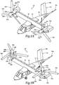
- Tiltrotor aircraft 10 includes a fuselage 12, a wing mount assembly 14 and a tail section 16 including rotatably mounted tail members 16a, 16b having control surfaces operable for horizontal and/or vertical stabilization during forward flight.
- a wing 18 is supported by fuselage 12. Coupled to outboard ends of wing 18 are propulsion assemblies 20a, 20b.
- Propulsion assembly 20a includes a fixed nacelle 22a that is coupled to wing 18 and houses an engine and a transmission.
- propulsion assembly 20a includes a pylon assembly 24a that is rotatable relative to fixed nacelle 22a between a generally horizontal orientation, as best seen in figure 1A , and a generally vertical orientation, as best seen in figure 1B .
- Pylon assembly 24a includes a proprotor assembly 26a including spinner 28a and proprotor blade assemblies 30a, which is rotatable relative to pylon assembly 24a responsive to torque and rotational energy provided by a rotor hub assembly and drive system mechanically coupled to the engine and transmission.
- propulsion assembly 20b includes a fixed nacelle 22b that houses an engine and transmission, a pylon assembly 24b that is rotatable relative to fixed nacelle 22b and a proprotor assembly 26b including spinner 28b and proprotor blade assemblies 30b, which is rotatable relative to pylon assembly 24b responsive to torque and rotational energy provided via a rotor hub assembly and drive system mechanically coupled to the engine and transmission housed by fixed nacelle 22b.
- the term “coupled” may include direct or indirect coupling by any means, including moving and/or non-moving mechanical connections.
- Figure 1A illustrates tiltrotor aircraft 10 in airplane or forward flight mode, in which proprotor assemblies 26a, 26b are rotating in a substantially vertical plane to provide a forward thrust enabling wing 18 to provide a lifting force responsive to forward airspeed, such that tiltrotor aircraft 10 flies much like a conventional propeller driven aircraft.
- Figure 1B illustrates tiltrotor aircraft 10 in helicopter or vertical takeoff and landing (VTOL) flight mode, in which proprotor assemblies 26a, 26b are rotating in a substantially horizontal plane to provide a lifting thrust such that tiltrotor aircraft 10 flies much like a conventional helicopter.
- VTOL vertical takeoff and landing
- tiltrotor aircraft 10 can be operated such that proprotor assemblies 26a, 26b are selectively positioned between forward flight mode and VTOL flight mode, which can be referred to as a conversion flight mode.
- tiltrotor aircraft 10 has been described as having one engine in each fixed nacelle 22a, 22b, it should be appreciated by those having ordinary skill in the art that other engine arrangements are possible and are considered to be within the scope of the present disclosure including, for example, alternatively or additionally having an engine housed within fuselage 12 that provides torque and rotational energy to both proprotor assemblies 26a, 26b.
- Spinners 28a, 28b are subjected to freestream airflow when tiltrotor aircraft 10 is in forward flight mode, as shown in figure 1A .
- Spinners 28a, 28b are elongated to form tapered leading portions 32a, 32b and substantially cylindrical aft portions 34a, 34b, respectively.
- Spinners 28a, 28b form rotor blade cutouts 36a, 36b that expose inner chambers 38a, 38b of spinners 28a, 28b, respectively.
- Proprotor blade assemblies 30a, 30b protrude radially from spinners 28a, 28b through rotor blade cutouts 36a, 36b, respectively.
- proprotor assemblies 26a, 26b may each include two, four, five or more proprotor blade assemblies and two, four, five or more rotor blade cutouts.
- Rotor blade cutouts 36a, 36b are formed at cylindrical aft portions 34a, 34b of spinners 28a, 28b, respectively.
- rotor blade cutouts 36a, 36b are substantially aligned or parallel with freestream airflow during forward flight such that the freestream airflow into inner chambers 38a, 38b of spinners 28a, 28b via rotor blade cutouts 36a, 36b is reduced, thereby reducing drag, including ram and momentum drag, experienced by tiltrotor aircraft 10.
- tiltrotor aircraft 10 is merely illustrative of a variety of aircraft that can implement the embodiments disclosed herein.
- spinners 28a, 28b may be used on any aircraft that utilizes a proprotor, propeller or rotor-based propulsion system.
- Other aircraft implementations can include hybrid aircraft, tiltwing aircraft, quad tiltrotor aircraft, unmanned aircraft, gyrocopters, airplanes, helicopters and the like.
- spinners 28a, 28b can be integrated into a variety of aircraft configurations.
- non-aircraft vehicles and devices can also implement the embodiments, including, but not limited to, automobiles or land-based vehicles.
- Proprotor assembly 100 includes a non-elongated spinner 102 from which three proprotor blade assemblies 104 protrude.
- Proprotor blade assemblies 104 include shanks 106 connecting proprotor blade assemblies 104 to a mast 108 via a rotor hub (not shown).
- Rotor blade cutouts 110 formed in spinner 102 provide holes through which shanks 106 connect proprotor blade assemblies 104 to mast 108.
- Rotor blade cutouts 110 accommodate the flapping envelope of proprotor blade assemblies 104, including flapping in the fore-aft direction 112.
- Rotor blade cutouts 110 may also accommodate lead-lag and pitching movements of proprotor blade assemblies 104.
- the flapping envelope of proprotor blade assemblies 104 may be expanded to increase control power in low speed and hover operations, as well as increase overall agility.
- flapping in fore-aft direction 112 may be expanded to a range between 12 and 18 degrees, such as 15 degrees, whereas previous tiltrotor aircraft may require a flapping envelope of 10.5 degrees or less.
- Larger rotor blade cutouts 110 may be necessary to accommodate such an expanded flapping envelope.
- Larger rotor blade cutouts 110 present a severe drag penalty for the tiltrotor aircraft when formed by non-elongated spinner 102, whose surface is tapered relative to freestream airflow 114.
- FIG. 2B shows the resulting profiles 118 of rotor blade cutouts 110 relative to freestream airflow 114 that create ram and momentum drag issues.
- Placement of rotor blade cutouts 110 on the tapered surface of spinner 102 causes leading edges 120a to have a distance 122 from central axis 124 of spinner 102 that is less than distance 126 between trailing edges 120b of rotor blade cutouts 110 and central axis 124.
- leading edges 120a are disposed more radially inward than trailing edges 120b.
- Such a configuration causes rotor blade cutouts 110 to be nonaligned with freestream airflow 114 to which spinner 102 is subjected during forward flight.
- Nonaligned rotor blade cutouts 110 also cause air exchange 130 between inner chamber 116 and the outside environment via rotor blade cutouts 110 during forward flight, which causes momentum drag for the tiltrotor aircraft.
- Air exchange 130 may be further exacerbated by swirling air 132 within inner chamber 116, which is caused by the entry of air into inner chamber 116 through rotor blade cutouts 110.
- leading edges 120a are more radially inward than trailing edges 120b, causing increased portions 134 of shanks 106 to be exposed to freestream airflow 114, the tiltrotor aircraft experiences additional profile drag. Accordingly, a need has arisen for an improved spinner that reduces or eliminates the drag-inducing effects caused by non-elongated spinner 102.
- Proprotor assembly 200 includes spinner 202, which is elongated to form a tapered leading portion 204 and a substantially cylindrical aft portion 206.
- Proprotor blade assemblies 208 protrude radially from spinner 202 through rotor blade cutouts 210 formed in spinner 202.
- Proprotor blade assemblies 208 are coupled, via shanks 212 and a rotor hub (not shown), to mast 214 located in inner chamber 216 of spinner 202.
- a dotted outline of non-elongated spinner 102 which was described in figures 2A-2C , is illustrated in figure 3A to contrast with the elongated spinner 202 of the illustrative embodiments.
- Rotor blade cutouts 210 are formed on cylindrical aft portion 206 of spinner 202 to reduce or eliminate freestream airflow 218 into inner chamber 216 via rotor blade cutouts 210 during forward flight, thereby reducing various types of drag experienced by the tiltrotor aircraft. While rotor blade cutouts 210 may expose inner chamber 216 to the environment outside of spinner 202, placement of rotor blade cutouts 210 on cylindrical aft portion 206 of spinner 202 reduces or eliminates the exposure of inner chamber 216 to freestream airflow 218 during forward flight.
- the projected frontal profile area of rotor blade cutouts 210 and inner chamber 216 is substantially reduced or eliminated by placing rotor blade cutouts 210 on cylindrical aft portion 206.
- Figure 3B may be contrasted with figure 2B , in which projected profile area 118 of rotor blade cutouts 110 is substantially larger and therefore more likely to allow freestream airflow into inner chamber 116 of spinner 102 and cause drag.
- rotor blade cutouts 210 are aligned and oriented substantially parallel to freestream airflow 218, as best seen in figure 3C , such that air substantially bypasses inner chamber 216 during forward flight.
- Cylindrical aft portion 206 has an outer surface 220 that is substantially parallel with freestream airflow 218 during forward flight, as best seen in figure 3C .
- Rotor blade cutouts 210 each include leading edges 222a and trailing edges 222b that form axes 224, which may substantially bisect each rotor blade cutout 210.
- Axes 224 are each substantially parallel to freestream airflow 218 during forward flight.
- Axes 224 are also substantially parallel to a forward direction 226 of motion in which tiltrotor aircraft moves during forward flight.
- leading and trailing edges 222a, 222b are each substantially the same distance 228 from central axis 230 extending through spinner 202.
- Rotor blade cutouts 210 each have a generally oval or stadium shape.
- rotor blade cutouts 210 have leading and trailing sides 232, 234 that are curved or arched and lateral sides 236, 238 that are substantially straight.
- rotor blade cutouts 210 may have other shapes than that which is illustrated, such as a rectangular, square, circular, triangular, irregular or other shape.
- Rotor blade cutouts 210 may be enlarged to accommodate expanded flapping envelopes for proprotor blade assemblies 208 in the fore-aft direction 240.
- rotor blade cutouts 210 may be sized to accommodate fore-aft flapping of proprotor blade assemblies 208 in a range between 12 to 18 degrees, such as 15 degrees.
- rotor blade cutouts 210 may be sized to accommodate fore-aft flapping of proprotor blade assemblies 208 of less than 12 degrees or greater than 18 degrees. Rotor blade cutouts 210 may also be sized to accommodate expanded lead-lag or pitching movement of proprotor blade assemblies 208.
- Inner chamber 216 may be any size or shape. For example, while inner chamber 216 is shown to provide fluid or air communication between rotor blade cutouts 210, inner chamber 216 may also include one or more cavities, voids or channels each adapted to contain shanks 212 or another portion of proprotor blade assemblies 208. Thus, inner chamber 216 may have any spatial configuration and be comprised of any number of individual inner chambers.
- Elongated spinner 202 reduces the drag on the tiltrotor aircraft in several respects.
- the alignment of rotor blade cutouts 210 with streamwise or freestream airflow over spinner 202 in forward flight reduces the exposed frontal area of rotor blade cutouts 210, as best seen in figure 3B , thereby reducing the associated ram drag.
- the reduction of freestream airflow 218 into inner chamber 216 via rotor blade cutouts 210 also reduces momentum drag by reducing the air exchanged into and out of spinner 202.
- spinner 202 By aligning rotor blade cutouts 210 to be parallel with freestream airflow 218, spinner 202 is wider at the location of shanks 212 such that increased portions 242 of shanks 212 are enclosed within spinner 202, thereby exposing reduced portions 244 of shanks 212 to freestream airflow 218 to minimize profile drag.
- Figure 3B may be contrasted to figure 2B , in which increased portion 134 was exposed to freestream airflow due to the leading edges of the rotor blade cutouts being more radially inward than the trailing edges of the rotor blade cutouts.
- Spinner 202 also minimizes drag on the tiltrotor aircraft by optimizing the airflow pressure along the length of spinner 202 such that air pressure and air velocity are reduced or minimized adjacent to rotor blade cutouts 210, as described in figure 4 below.
- Spinner 202 achieves reduced drag for the tiltrotor aircraft without adding an undue amount of weight, size or complexity to the tiltrotor aircraft.
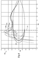
- a graph illustrating surface pressure coefficients along the lengths of various spinner shapes is schematically illustrated and generally designated 300.
- Graph 300 also shows the impact that various spinner shapes have on the location of the air pressure spike experienced by such spinners.
- spinner 302 corresponds to pressure coefficient curve 302a
- spinner 304 corresponds to pressure coefficient curve 304a
- spinner 306 corresponds to pressure coefficient curve 306a
- spinner 308 corresponds to pressure coefficient curve 308a.
- the location of the leading edge of the rotor blade cutouts on the illustrated spinners is represented in graph 300 by line 310.
- the nose shape and overall length of the spinners of the illustrative embodiments are configured so that the air pressure spike occurs in front of rotor blade cutouts 310 and the airflow has decelerated prior to reaching rotor blade cutouts 310 and proprotor blade assembly shanks, thereby reducing the drag caused by rotor blade cutouts 310 and proprotor blade assembly shanks.
- Spinners 304, 306 and 308 each have air pressures at rotor blade cutouts 310 that are lower than the air pressure for spinner 302, which is the stubbiest, shortest and least elongated of all the spinners in graph 300.
- the peaks, or magnitudes, of the pressure spikes for spinners 304, 306 and 308 are lower than the peak of the pressure spike for spinner 302, thereby reducing spinner skin friction drag for spinners 304, 306 and 308. Also, the pressure spike for spinners 304, 306 and 308 all occur further from rotor blade cutouts 310 than the pressure spike for spinner 302. Lower air pressure for spinners 304, 306 and 308 corresponds to a lower air velocity at rotor blade cutouts 310, and because drag is a function of air velocity, spinners 304, 306 and 308 cause a lower amount of drag than spinner 302.
- the spinner is elongated such that air pressure and air velocity is reduced or minimized adjacent to rotor blade cutouts 310, thereby reducing the drag attributable to rotor blade cutouts 310 and proprotor blade assembly shanks during forward flight.
- the tapered portion of the spinner may be shaped such that the peak, or magnitude, of the pressure spike caused by the spinner is reduced, which correspondingly reduces skin friction drag on the spinner.
- the spinner of the illustrative embodiments may also be elongated such that the distance between rotor blade cutout 310 and the pressure spike along the surface of the spinner is increased, thereby providing more distance for pressure recovery so that the air velocity slows or stabilizes by the time it reaches rotor blade cutouts 310.
- the additional distance provided by the elongated spinner design provides additional room for the airflow to go around the leading portion or nose of the spinner and decelerate by the time it gets to rotor blade cutouts 310, thereby minimizing air pressure and air velocity adjacent to rotor blade cutouts 310 during forward flight.
- Shorter spinner designs such as spinner 302 force air to accelerate more quickly around the leading portion of the spinner, thereby causing the associated pressure spike to occur closer to rotor blade cutouts 310, which can increase drag.
- graph 300 illustrates that spinner 308, which is the most elongated of all the spinners, has the lowest pressure coefficient adjacent to rotor blade cutouts 310.
- ram drag may be reduced for elongated spinner designs because airflow thereover has a reduced pressure and velocity adjacent to rotor blade cutouts 310, causing less air to enter the spinner via rotor blade cutouts 310 and reducing the profile drag caused by the shanks protruding therefrom.
- elongated spinner 400 forms rotor blade cutouts 402.
- Diverter brows 404 are each disposed adjacent leading edges 406 of respective rotor blade cutouts 402 to divert airflow away from rotor blade cutouts 402.
- Diverter brows 404 may be placed anywhere in front of rotor blade cutouts 402 to reduce the airflow into rotor blade cutouts 402 and minimize the airflow impinging on shanks 408.
- Diverter brows 404 radially protrude from spinner 400 to shield an increased portion 410 of shanks 408 from freestream airflow during forward flight, thereby reducing the drag caused by shanks 408.
- Diverter brows 404 have rounded forward edges 412 that approximate an arch shape.
- the forward edges of diverter brows 404 may also have other aerodynamic shapes, such as pointed, irregular or non-rounded shapes.
- diverter brows 414 may each be a triangular flap that radially protrudes from spinner 416.
- the radial protrusion of triangular flaps 414 also shields an increased portion of each shank protruding from rotor blade cutouts 418.
- Diverter brows 404, 414 may protrude radially by any distance suitable for the application, and may be any shape that helps to reduce drag of the tiltrotor aircraft.
Landscapes
- Engineering & Computer Science (AREA)
- Aviation & Aerospace Engineering (AREA)
- Structures Of Non-Positive Displacement Pumps (AREA)
Abstract
Description
- The present disclosure relates, in general, to spinners for use on aircraft and, in particular, to elongated spinners having rotor blade cutouts oriented to reduce the drag experienced by tiltrotor aircraft.
- The hub of an aircraft proprotor or propeller is typically covered by a spinner. Typically, spinners have an aerodynamic shape that streamlines an aircraft and helps to smoothen the airflow through the blades of the proprotor or propeller and over the surfaces aft of the proprotor or propeller. The blades of a proprotor or propeller may radially protrude from the spinner via cutouts, or holes, in the spinner. The cutouts may allow the blades to flap or move in various directions, including the fore-aft and lead-lag directions, and also allow the blades to pitch at various angles. Current spinner and cutout configurations, however, present a number of drag issues for the aircraft. For example, airflow during forward flight can enter the spinner through the cutouts, thereby creating ram drag. Cutouts may expose large portions of the blade shanks to freestream airflow, further causing ram or profile drag. The exchange of air into and out of the cutouts contributes to the momentum drag experienced by the aircraft. Also, current spinners are shaped such that air pressure is at a maximum near the cutouts, which leads to high air velocity and increased dynamic pressure near the cutouts and a further increase in the aforementioned drag effects. Previous techniques for reducing cutout-induced drag, such as sliding seals, have reliability and maintenance disadvantages and add undue weight, cost and complexity. Accordingly, a need has arisen for spinner and cutout configurations that reduce the various types of drag caused by current spinners while avoiding unnecessary weight, cost and complexity.
- In a first aspect, the present disclosure is directed to a proprotor assembly for a tiltrotor aircraft having a forward flight mode. The proprotor assembly includes a spinner subjected to freestream airflow during forward flight. The spinner has a tapered leading portion and a substantially cylindrical aft portion. The spinner forms a plurality of rotor blade cutouts exposing an inner chamber. The proprotor assembly includes a plurality of proprotor blade assemblies protruding radially from the spinner through the rotor blade cutouts. The rotor blade cutouts are formed at the substantially cylindrical aft portion of the spinner to reduce the freestream airflow into the inner chamber via the rotor blade cutouts during forward flight, thereby reducing drag experienced by the tiltrotor aircraft.
- In some embodiments, the substantially cylindrical aft portion of the spinner may have an outer surface substantially parallel with the freestream airflow during forward flight. In certain embodiments, the rotor blade cutouts may be aligned with the freestream airflow such that air substantially bypasses the inner chamber during forward flight. In some embodiments, placement of the rotor blade cutouts at the substantially cylindrical aft portion of the spinner may reduce exposure of the inner chamber of the spinner to freestream airflow during forward flight. In certain embodiments, the rotor blade cutouts may be oriented substantially parallel to the freestream airflow during forward flight. In some embodiments, the rotor blade cutouts each may include a leading edge and a trailing edge forming an axis, the axes of the rotor blade cutouts each substantially parallel to the freestream airflow during forward flight. In certain embodiments, the tiltrotor aircraft moves in a forward direction during forward flight and the rotor blade cutouts may each include a leading edge and a trailing edge forming an axis, the axes of the rotor blade cutouts each substantially parallel to the forward direction.
- In some embodiments, the spinner may have a central axis extending therethrough, the rotor blade cutouts may each include a leading edge and a trailing edge, the leading edge of each rotor blade cutout may have a distance L from the central axis, the trailing edge of each rotor blade cutout may have a distance T from the central axis and L may be substantially equal to T. In certain embodiments, the rotor blade cutouts may each form an oval shape. In some embodiments, the rotor blade cutouts may each further comprise a leading side, a trailing side, a first lateral side and a second lateral side. In such embodiments, the leading and trailing sides may be curved and the first and second lateral sides may be substantially straight. In certain embodiments, reduction of the freestream airflow into the inner chamber may reduce air exchange through the rotor blade cutouts, thereby reducing momentum drag experienced by the tiltrotor aircraft.
- In some embodiments, the proprotor blade assemblies may each include a shank extending through a respective one of the rotor blade cutouts, and placement of the rotor blade cutouts at the substantially cylindrical aft portion of the spinner may shield an increased portion of each shank from the freestream airflow during forward flight, thereby reducing drag caused by the shanks. In certain embodiments, the spinner may be elongated to reduce air pressure and air velocity adjacent to the rotor blade cutouts, thereby reducing drag attributable to the rotor blade cutouts during forward flight. In some embodiments, airflow over the spinner during forward flight may experience a pressure spike, and the spinner may be elongated to increase the distance between the pressure spike and the rotor blade cutouts, thereby minimizing air pressure and air velocity adjacent to the rotor blade cutouts and rotor blade shanks during forward flight. In certain embodiments, the rotor blade cutouts may each have a leading edge, and the spinner may include a plurality of diverter brows, each of which may be aerodynamically optimized and disposed adjacent to the leading edge of a respective rotor blade cutout to divert airflow away from the rotor blade cutouts. In some embodiments, the diverter brows may each have a rounded forward edge. In certain embodiments, the diverter brows may each form an arch shape. In some embodiments, the diverter brows may each include a triangular flap. In some embodiments, the proprotor blade assemblies may each include a shank extending through a respective one of the rotor blade cutouts, and the diverter brows may radially protrude from the spinner to shield an increased portion of each shank from the freestream airflow during forward flight, thereby reducing drag caused by the shanks.
- In a second aspect, the present disclosure is directed to a tiltrotor aircraft having a forward flight mode. The tiltrotor aircraft including a fuselage, a wing supported by the fuselage and at least one propulsion assembly coupled to the wing and including a proprotor assembly. The proprotor assembly includes a spinner subjected to freestream airflow during forward flight. The spinner has a tapered leading portion and a substantially cylindrical aft portion. The spinner forms a plurality of rotor blade cutouts exposing an inner chamber. The proprotor assembly includes a plurality of proprotor blade assemblies protruding radially from the spinner through the rotor blade cutouts. The rotor blade cutouts are formed at the substantially cylindrical aft portion of the spinner to reduce freestream airflow into the inner chamber via the rotor blade cutouts during forward flight, thereby reducing drag experienced by the tiltrotor aircraft.
- In some embodiments, the propulsion assembly may include a fixed nacelle coupled to the wing and a pylon assembly rotatably coupled to the fixed nacelle, the pylon assembly including the proprotor assembly. In certain embodiments, the spinner may be rotatable relative to the pylon assembly. In some embodiments, reduction of the freestream airflow into the inner chamber may reduce ram drag experienced by the tiltrotor aircraft. In certain embodiments, the proprotor blade assemblies may include three or more proprotor blade assemblies and the rotor blade cutouts may include three or more rotor blade cutouts.
- For a more complete understanding of the features and advantages of the present disclosure, reference is now made to the detailed description along with the accompanying figures in which corresponding numerals in the different figures refer to corresponding parts and in which:
-
Figures 1A-1B are schematic illustrations of a tiltrotor aircraft having elongated spinners in accordance with embodiments of the present disclosure; -
Figures 2A-2C are various views of a proprotor assembly utilizing a non-elongated spinner; -
Figures 3A-3C are various views of a proprotor assembly utilizing an elongated spinner in accordance with embodiments of the present disclosure; -
Figure 4 is a graph illustrating surface pressure coefficients along the lengths of various spinner shapes; -
Figures 5A-5D are various views of an elongated spinner having arch-shaped diverter brows in accordance with embodiments of the present disclosure; and -
Figures 6A-6C are various views of an elongated spinner having diverter brow flaps in accordance with embodiments of the present disclosure. - While the making and using of various embodiments of the present disclosure are discussed in detail below, it should be appreciated that the present disclosure provides many applicable inventive concepts, which can be embodied in a wide variety of specific contexts. The specific embodiments discussed herein are merely illustrative and do not delimit the scope of the present disclosure. In the interest of clarity, all features of an actual implementation may not be described in this specification. It will of course be appreciated that in the development of any such actual embodiment, numerous implementation-specific decisions must be made to achieve the developer's specific goals, such as compliance with system-related and business-related constraints, which will vary from one implementation to another. Moreover, it will be appreciated that such a development effort might be complex and time-consuming but would nevertheless be a routine undertaking for those of ordinary skill in the art having the benefit of this disclosure.
- In the specification, reference may be made to the spatial relationships between various components and to the spatial orientation of various aspects of components as the devices are depicted in the attached drawings. However, as will be recognized by those skilled in the art after a complete reading of the present disclosure, the devices, members, apparatuses, and the like described herein may be positioned in any desired orientation. Thus, the use of terms such as "above," "below," "upper," "lower" or other like terms to describe a spatial relationship between various components or to describe the spatial orientation of aspects of such components should be understood to describe a relative relationship between the components or a spatial orientation of aspects of such components, respectively, as the devices described herein may be oriented in any desired direction.
- Referring to
figures 1A-1B in the drawing, a tiltrotor aircraft is schematically illustrated and generally designated 10.Tiltrotor aircraft 10 includes afuselage 12, awing mount assembly 14 and atail section 16 including rotatably mountedtail members wing 18 is supported byfuselage 12. Coupled to outboard ends ofwing 18 arepropulsion assemblies Propulsion assembly 20a includes a fixednacelle 22a that is coupled towing 18 and houses an engine and a transmission. In addition,propulsion assembly 20a includes apylon assembly 24a that is rotatable relative to fixednacelle 22a between a generally horizontal orientation, as best seen infigure 1A , and a generally vertical orientation, as best seen infigure 1B .Pylon assembly 24a includes aproprotor assembly 26a including spinner 28a andproprotor blade assemblies 30a, which is rotatable relative topylon assembly 24a responsive to torque and rotational energy provided by a rotor hub assembly and drive system mechanically coupled to the engine and transmission. Similarly,propulsion assembly 20b includes a fixednacelle 22b that houses an engine and transmission, apylon assembly 24b that is rotatable relative to fixednacelle 22b and aproprotor assembly 26b including spinner 28b andproprotor blade assemblies 30b, which is rotatable relative topylon assembly 24b responsive to torque and rotational energy provided via a rotor hub assembly and drive system mechanically coupled to the engine and transmission housed by fixednacelle 22b. As used herein, the term "coupled" may include direct or indirect coupling by any means, including moving and/or non-moving mechanical connections. -
Figure 1A illustratestiltrotor aircraft 10 in airplane or forward flight mode, in whichproprotor assemblies thrust enabling wing 18 to provide a lifting force responsive to forward airspeed, such thattiltrotor aircraft 10 flies much like a conventional propeller driven aircraft.Figure 1B illustratestiltrotor aircraft 10 in helicopter or vertical takeoff and landing (VTOL) flight mode, in whichproprotor assemblies tiltrotor aircraft 10 flies much like a conventional helicopter. It should be appreciated thattiltrotor aircraft 10 can be operated such thatproprotor assemblies tiltrotor aircraft 10 has been described as having one engine in each fixednacelle fuselage 12 that provides torque and rotational energy to bothproprotor assemblies -
Spinners tiltrotor aircraft 10 is in forward flight mode, as shown infigure 1A .Spinners portions aft portions Spinners rotor blade cutouts inner chambers spinners Proprotor blade assemblies spinners rotor blade cutouts proprotor assembly proprotor blade assemblies rotor blade cutouts proprotor assemblies Rotor blade cutouts aft portions spinners rotor blade cutouts aft portions spinners rotor blade cutouts inner chambers spinners rotor blade cutouts tiltrotor aircraft 10. - It should be appreciated that
tiltrotor aircraft 10 is merely illustrative of a variety of aircraft that can implement the embodiments disclosed herein. Indeed,spinners spinners - Referring to
figures 2A-2C in the drawings, a proprotor assembly for a tiltrotor aircraft is schematically illustrated and generally designated 100.Proprotor assembly 100 includes anon-elongated spinner 102 from which threeproprotor blade assemblies 104 protrude.Proprotor blade assemblies 104 includeshanks 106 connectingproprotor blade assemblies 104 to amast 108 via a rotor hub (not shown).Rotor blade cutouts 110 formed inspinner 102 provide holes through whichshanks 106 connectproprotor blade assemblies 104 tomast 108.Rotor blade cutouts 110 accommodate the flapping envelope ofproprotor blade assemblies 104, including flapping in the fore-aft direction 112.Rotor blade cutouts 110 may also accommodate lead-lag and pitching movements ofproprotor blade assemblies 104. - In some applications, the flapping envelope of
proprotor blade assemblies 104 may be expanded to increase control power in low speed and hover operations, as well as increase overall agility. For example, flapping in fore-aft direction 112 may be expanded to a range between 12 and 18 degrees, such as 15 degrees, whereas previous tiltrotor aircraft may require a flapping envelope of 10.5 degrees or less. Largerrotor blade cutouts 110 may be necessary to accommodate such an expanded flapping envelope. Largerrotor blade cutouts 110, however, present a severe drag penalty for the tiltrotor aircraft when formed bynon-elongated spinner 102, whose surface is tapered relative tofreestream airflow 114. Becauserotor blade cutouts 110 are formed on the tapered surface ofspinner 102,inner chamber 116 ofspinner 102 is exposed tofreestream airflow 114 during forward flight, as best seen infigures 2B and 2C , thereby creating ram and momentum drag for the tiltrotor aircraft.Figure 2B shows the resultingprofiles 118 ofrotor blade cutouts 110 relative tofreestream airflow 114 that create ram and momentum drag issues. Placement ofrotor blade cutouts 110 on the tapered surface ofspinner 102causes leading edges 120a to have adistance 122 fromcentral axis 124 ofspinner 102 that is less thandistance 126 between trailingedges 120b ofrotor blade cutouts 110 andcentral axis 124. Thus, leadingedges 120a are disposed more radially inward than trailingedges 120b. Such a configuration causesrotor blade cutouts 110 to be nonaligned withfreestream airflow 114 to whichspinner 102 is subjected during forward flight. - Nonaligned
rotor blade cutouts 110 also causeair exchange 130 betweeninner chamber 116 and the outside environment viarotor blade cutouts 110 during forward flight, which causes momentum drag for the tiltrotor aircraft.Air exchange 130 may be further exacerbated by swirlingair 132 withininner chamber 116, which is caused by the entry of air intoinner chamber 116 throughrotor blade cutouts 110. Also, because leadingedges 120a are more radially inward than trailingedges 120b, causing increasedportions 134 ofshanks 106 to be exposed tofreestream airflow 114, the tiltrotor aircraft experiences additional profile drag. Accordingly, a need has arisen for an improved spinner that reduces or eliminates the drag-inducing effects caused bynon-elongated spinner 102. - Referring to
figures 3A-3C in the drawings, a proprotor assembly for a tiltrotor aircraft is schematically illustrated and generally designated 200.Proprotor assembly 200 includesspinner 202, which is elongated to form a tapered leadingportion 204 and a substantially cylindricalaft portion 206.Proprotor blade assemblies 208 protrude radially fromspinner 202 throughrotor blade cutouts 210 formed inspinner 202.Proprotor blade assemblies 208 are coupled, viashanks 212 and a rotor hub (not shown), tomast 214 located ininner chamber 216 ofspinner 202. A dotted outline ofnon-elongated spinner 102, which was described infigures 2A-2C , is illustrated infigure 3A to contrast with theelongated spinner 202 of the illustrative embodiments. -
Rotor blade cutouts 210 are formed on cylindricalaft portion 206 ofspinner 202 to reduce or eliminatefreestream airflow 218 intoinner chamber 216 viarotor blade cutouts 210 during forward flight, thereby reducing various types of drag experienced by the tiltrotor aircraft. Whilerotor blade cutouts 210 may exposeinner chamber 216 to the environment outside ofspinner 202, placement ofrotor blade cutouts 210 on cylindricalaft portion 206 ofspinner 202 reduces or eliminates the exposure ofinner chamber 216 tofreestream airflow 218 during forward flight. As best seen infigure 3B , the projected frontal profile area ofrotor blade cutouts 210 andinner chamber 216 is substantially reduced or eliminated by placingrotor blade cutouts 210 on cylindricalaft portion 206.Figure 3B may be contrasted withfigure 2B , in which projectedprofile area 118 ofrotor blade cutouts 110 is substantially larger and therefore more likely to allow freestream airflow intoinner chamber 116 ofspinner 102 and cause drag. In the illustrative embodiments,rotor blade cutouts 210 are aligned and oriented substantially parallel tofreestream airflow 218, as best seen infigure 3C , such that air substantially bypassesinner chamber 216 during forward flight. Cylindricalaft portion 206 has anouter surface 220 that is substantially parallel withfreestream airflow 218 during forward flight, as best seen infigure 3C . -
Rotor blade cutouts 210 each include leadingedges 222a and trailingedges 222b that form axes 224, which may substantially bisect eachrotor blade cutout 210.Axes 224 are each substantially parallel tofreestream airflow 218 during forward flight.Axes 224 are also substantially parallel to aforward direction 226 of motion in which tiltrotor aircraft moves during forward flight. Unlikespinner 102 illustrated infigures 2A-2C , leading and trailingedges same distance 228 fromcentral axis 230 extending throughspinner 202. -
Rotor blade cutouts 210 each have a generally oval or stadium shape. In particular,rotor blade cutouts 210 have leading and trailingsides lateral sides rotor blade cutouts 210 may have other shapes than that which is illustrated, such as a rectangular, square, circular, triangular, irregular or other shape.Rotor blade cutouts 210 may be enlarged to accommodate expanded flapping envelopes forproprotor blade assemblies 208 in the fore-aft direction 240. For example,rotor blade cutouts 210 may be sized to accommodate fore-aft flapping ofproprotor blade assemblies 208 in a range between 12 to 18 degrees, such as 15 degrees. In other embodiments,rotor blade cutouts 210 may be sized to accommodate fore-aft flapping ofproprotor blade assemblies 208 of less than 12 degrees or greater than 18 degrees.Rotor blade cutouts 210 may also be sized to accommodate expanded lead-lag or pitching movement ofproprotor blade assemblies 208.Inner chamber 216 may be any size or shape. For example, whileinner chamber 216 is shown to provide fluid or air communication betweenrotor blade cutouts 210,inner chamber 216 may also include one or more cavities, voids or channels each adapted to containshanks 212 or another portion ofproprotor blade assemblies 208. Thus,inner chamber 216 may have any spatial configuration and be comprised of any number of individual inner chambers. -
Elongated spinner 202 reduces the drag on the tiltrotor aircraft in several respects. The alignment ofrotor blade cutouts 210 with streamwise or freestream airflow overspinner 202 in forward flight reduces the exposed frontal area ofrotor blade cutouts 210, as best seen infigure 3B , thereby reducing the associated ram drag. The reduction offreestream airflow 218 intoinner chamber 216 viarotor blade cutouts 210 also reduces momentum drag by reducing the air exchanged into and out ofspinner 202. By aligningrotor blade cutouts 210 to be parallel withfreestream airflow 218,spinner 202 is wider at the location ofshanks 212 such that increasedportions 242 ofshanks 212 are enclosed withinspinner 202, thereby exposing reducedportions 244 ofshanks 212 tofreestream airflow 218 to minimize profile drag. The placement ofrotor blade cutouts 210 on cylindricalaft portion 206 shields increasedportions 242 ofshanks 212 by adistance 246 fromfreestream airflow 218 during forward flight. -
Figure 3B may be contrasted tofigure 2B , in which increasedportion 134 was exposed to freestream airflow due to the leading edges of the rotor blade cutouts being more radially inward than the trailing edges of the rotor blade cutouts.Spinner 202 also minimizes drag on the tiltrotor aircraft by optimizing the airflow pressure along the length ofspinner 202 such that air pressure and air velocity are reduced or minimized adjacent torotor blade cutouts 210, as described infigure 4 below.Spinner 202 achieves reduced drag for the tiltrotor aircraft without adding an undue amount of weight, size or complexity to the tiltrotor aircraft. - Referring to
figure 4 in the drawings, a graph illustrating surface pressure coefficients along the lengths of various spinner shapes is schematically illustrated and generally designated 300.Graph 300 also shows the impact that various spinner shapes have on the location of the air pressure spike experienced by such spinners. Ingraph 300, spinner 302 corresponds to pressurecoefficient curve 302a,spinner 304 corresponds to pressurecoefficient curve 304a,spinner 306 corresponds to pressurecoefficient curve 306a andspinner 308 corresponds to pressurecoefficient curve 308a. The location of the leading edge of the rotor blade cutouts on the illustrated spinners is represented ingraph 300 byline 310. The nose shape and overall length of the spinners of the illustrative embodiments are configured so that the air pressure spike occurs in front ofrotor blade cutouts 310 and the airflow has decelerated prior to reachingrotor blade cutouts 310 and proprotor blade assembly shanks, thereby reducing the drag caused byrotor blade cutouts 310 and proprotor blade assembly shanks.Spinners rotor blade cutouts 310 that are lower than the air pressure for spinner 302, which is the stubbiest, shortest and least elongated of all the spinners ingraph 300. The peaks, or magnitudes, of the pressure spikes forspinners spinners spinners rotor blade cutouts 310 than the pressure spike for spinner 302. Lower air pressure forspinners rotor blade cutouts 310, and because drag is a function of air velocity,spinners rotor blade cutouts 310, thereby reducing the drag attributable torotor blade cutouts 310 and proprotor blade assembly shanks during forward flight. Also in the illustrative embodiments, the tapered portion of the spinner may be shaped such that the peak, or magnitude, of the pressure spike caused by the spinner is reduced, which correspondingly reduces skin friction drag on the spinner. - The spinner of the illustrative embodiments may also be elongated such that the distance between
rotor blade cutout 310 and the pressure spike along the surface of the spinner is increased, thereby providing more distance for pressure recovery so that the air velocity slows or stabilizes by the time it reachesrotor blade cutouts 310. The additional distance provided by the elongated spinner design provides additional room for the airflow to go around the leading portion or nose of the spinner and decelerate by the time it gets torotor blade cutouts 310, thereby minimizing air pressure and air velocity adjacent torotor blade cutouts 310 during forward flight. Shorter spinner designs, such as spinner 302, force air to accelerate more quickly around the leading portion of the spinner, thereby causing the associated pressure spike to occur closer torotor blade cutouts 310, which can increase drag. Indeed,graph 300 illustrates thatspinner 308, which is the most elongated of all the spinners, has the lowest pressure coefficient adjacent torotor blade cutouts 310. Thus, ram drag may be reduced for elongated spinner designs because airflow thereover has a reduced pressure and velocity adjacent torotor blade cutouts 310, causing less air to enter the spinner viarotor blade cutouts 310 and reducing the profile drag caused by the shanks protruding therefrom. - Referring to
figures 5A-5D and6A-6C in the drawings, a variety of diverter brows are implemented on elongated spinners of the illustrative embodiments. Referring specifically tofigures 5A-5D ,elongated spinner 400 formsrotor blade cutouts 402.Diverter brows 404 are each disposed adjacent leadingedges 406 of respectiverotor blade cutouts 402 to divert airflow away fromrotor blade cutouts 402.Diverter brows 404 may be placed anywhere in front ofrotor blade cutouts 402 to reduce the airflow intorotor blade cutouts 402 and minimize the airflow impinging onshanks 408.Diverter brows 404 radially protrude fromspinner 400 to shield an increasedportion 410 ofshanks 408 from freestream airflow during forward flight, thereby reducing the drag caused byshanks 408.Diverter brows 404 have rounded forward edges 412 that approximate an arch shape. The forward edges of diverter brows 404 may also have other aerodynamic shapes, such as pointed, irregular or non-rounded shapes. For example, as shown infigures 6A-6C ,diverter brows 414 may each be a triangular flap that radially protrudes fromspinner 416. The radial protrusion oftriangular flaps 414 also shields an increased portion of each shank protruding fromrotor blade cutouts 418.Diverter brows - The foregoing description of embodiments of the disclosure has been presented for purposes of illustration and description. It is not intended to be exhaustive or to limit the disclosure to the precise form disclosed, and modifications and variations are possible in light of the above teachings or may be acquired from practice of the disclosure. The embodiments were chosen and described in order to explain the principals of the disclosure and its practical application to enable one skilled in the art to utilize the disclosure in various embodiments and with various modifications as are suited to the particular use contemplated. Other substitutions, modifications, changes and omissions may be made in the design, operating conditions and arrangement of the embodiments without departing from the scope of the present disclosure. Such modifications and combinations of the illustrative embodiments as well as other embodiments will be apparent to persons skilled in the art upon reference to the description. It is, therefore, intended that the appended claims encompass any such modifications or embodiments.
Claims (15)
- A proprotor assembly for a tiltrotor aircraft having a forward flight mode, the proprotor assembly comprising:a spinner subjected to freestream airflow during forward flight, the spinner having a tapered leading portion and a substantially cylindrical aft portion, the spinner forming a plurality of rotor blade cutouts exposing an inner chamber; anda plurality of proprotor blade assemblies protruding radially from the spinner through the rotor blade cutouts;wherein the rotor blade cutouts are formed in the substantially cylindrical aft portion of the spinner to reduce the freestream airflow into the inner chamber via the rotor blade cutouts during forward flight, thereby reducing drag experienced by the tiltrotor aircraft.
- The proprotor assembly as recited in claim 1 wherein the substantially cylindrical aft portion of the spinner has an outer surface substantially parallel with the freestream airflow during forward flight.
- The proprotor assembly as recited in claim 1 or in claim 2, wherein the rotor blade cutouts are aligned with the freestream airflow such that air substantially bypasses the inner chamber during forward flight.
- The proprotor assembly as recited in claim 1 or in claim 2 or in claim 3,
wherein the rotor blade cutouts are oriented substantially parallel to the freestream airflow during forward flight. - The proprotor assembly as recited in claim 1, or in any of claims 2 to 4,
wherein the rotor blade cutouts each include a leading edge and a trailing edge forming an axis therebetween, the axes of the rotor blade cutouts each substantially parallel to the freestream airflow during forward flight. - The proprotor assembly as recited in claim 1, or in any of claims 2 to 5,
wherein the spinner has a central axis extending therethrough;
wherein the rotor blade cutouts each include a leading edge and a trailing edge;
wherein the leading edge of each rotor blade cutout has a distance L from the central axis and the trailing edge of each rotor blade cutout has a distance T from the central axis; and
wherein L is substantially equal to T. - The proprotor assembly as recited in claim 1, or in any of claims 2 to 6,
wherein the rotor blade cutouts each form an oval shape, and optionally or preferably,
wherein the rotor blade cutouts each further comprise a leading side, a trailing side, a first lateral side and a second lateral side; and
wherein the leading and trailing sides are curved and the first and second lateral sides are substantially straight. - The proprotor assembly as recited in claim 1, or in any of claims 2 to 7,
wherein the proprotor blade assemblies each include a shank extending through a respective one of the rotor blade cutouts; and
wherein placement of the rotor blade cutouts at the substantially cylindrical aft portion of the spinner shields an increased portion of each shank from the freestream airflow during forward flight, thereby reducing drag caused by the shanks. - The proprotor assembly as recited in claim 1, or in any of claims 2 to 8,
wherein the spinner is elongated to reduce air pressure and air velocity adjacent to the rotor blade cutouts, thereby reducing drag attributable to the rotor blade cutouts during forward flight, and optionally or preferably,
wherein airflow over the spinner during forward flight experiences a pressure spike; and
wherein the spinner is elongated to increase the distance between the pressure spike and the rotor blade cutouts, thereby reducing air pressure and air velocity adjacent to the rotor blade cutouts during forward flight. - The proprotor assembly as recited in claim 1, or in any of claims 2 to 9,
wherein the rotor blade cutouts each have a leading edge; and
wherein the spinner further comprises a plurality of diverter brows each disposed adjacent to the leading edge of a respective rotor blade cutout to divert airflow away from the rotor blade cutouts. - The proprotor assembly as recited in claim 10, wherein the diverter brows each have a rounded forward edge; and/or, wherein the diverter brows each further comprise a triangular flap.
- The proprotor assembly as recited in claim 10 or in claim 11, wherein the proprotor blade assemblies each include a shank extending through a respective one of the rotor blade cutouts; and
wherein the diverter brows radially protrude from the spinner to shield an increased portion of each shank from the freestream airflow during forward flight, thereby reducing drag caused by the shanks. - A tiltrotor aircraft having a forward flight mode, the tiltrotor aircraft comprising:a fuselage;a wing supported by the fuselage; andat least one propulsion assembly coupled to the wing, each propulsion assembly including a proprotor assembly comprising:a spinner subjected to freestream airflow during forward flight, the spinner having a tapered leading portion and a substantially cylindrical aft portion, the spinner forming a plurality of rotor blade cutouts exposing an inner chamber; anda plurality of proprotor blade assemblies protruding radially from the spinner through the rotor blade cutouts;wherein the rotor blade cutouts are formed in the substantially cylindrical aft portion of the spinner to reduce freestream airflow into the inner chamber via the rotor blade cutouts during forward flight, thereby reducing drag experienced by the tiltrotor aircraft.
- The tiltrotor aircraft as recited in claim 13, wherein the propulsion assembly further comprises:a fixed nacelle coupled to the wing; anda pylon assembly rotatably coupled to the fixed nacelle, the pylon assembly including the proprotor assembly, and optionally or preferably,wherein the spinner is rotatable relative to the pylon assembly.
- The proprotor assembly as recited in claim 13 or in claim 14, wherein the rotor blade cutouts each include a leading edge and a trailing edge forming an axis therebetween, the axes of the rotor blade cutouts each substantially parallel to the freestream airflow during forward flight; and/or
wherein the plurality of proprotor blade assemblies further comprises three or more proprotor blade assemblies; and
wherein the plurality of rotor blade cutouts further comprises three or more rotor blade cutouts.
Applications Claiming Priority (1)
| Application Number | Priority Date | Filing Date | Title |
|---|---|---|---|
| US15/605,545 US10589842B2 (en) | 2017-05-25 | 2017-05-25 | Spinners for use on tiltrotor aircraft |
Publications (2)
| Publication Number | Publication Date |
|---|---|
| EP3406517A1 true EP3406517A1 (en) | 2018-11-28 |
| EP3406517B1 EP3406517B1 (en) | 2019-08-28 |
Family
ID=60702355
Family Applications (1)
| Application Number | Title | Priority Date | Filing Date |
|---|---|---|---|
| EP17208887.4A Active EP3406517B1 (en) | 2017-05-25 | 2017-12-20 | Spinners for use on tiltrotor aircraft |
Country Status (2)
| Country | Link |
|---|---|
| US (1) | US10589842B2 (en) |
| EP (1) | EP3406517B1 (en) |
Families Citing this family (2)
| Publication number | Priority date | Publication date | Assignee | Title |
|---|---|---|---|---|
| JP7436499B2 (en) * | 2019-03-21 | 2024-02-21 | エーエムエスエル イノベーションズ ピーティーワイ リミテッド | Vertical takeoff and landing (VTOL) aircraft |
| US12486026B1 (en) * | 2022-12-13 | 2025-12-02 | Wisk Aero Llc | Aerodynamic rotor blade strake |
Citations (5)
| Publication number | Priority date | Publication date | Assignee | Title |
|---|---|---|---|---|
| GB518873A (en) * | 1938-09-01 | 1940-03-11 | Dehavilland Aircraft | Improvements relating to spinners and like fairings for airscrews |
| US2346680A (en) * | 1941-07-03 | 1944-04-18 | Harper Elwood | Propeller spinner |
| EP2340992A2 (en) * | 2009-12-29 | 2011-07-06 | Hamilton Sundstrand Corporation | Method for propeller blade root flow control by airflow through spinner |
| EP2657130A1 (en) * | 2012-04-25 | 2013-10-30 | Bell Helicopter Textron Inc. | Aircraft rotor with discrete flap hinge |
| EP2930398A1 (en) * | 2014-04-10 | 2015-10-14 | Bell Helicopter Textron Inc. | Variable speed aircraft transmission |
Family Cites Families (7)
| Publication number | Priority date | Publication date | Assignee | Title |
|---|---|---|---|---|
| GB155902A (en) * | 1919-09-23 | 1920-12-23 | Ernest Abington Vessey | Improvements relating to screw propellers |
| US2408677A (en) * | 1942-03-23 | 1946-10-01 | Rotol Ltd | Propeller spinner |
| GB566427A (en) * | 1943-07-20 | 1944-12-29 | Dehavilland Aircraft | Improvements in propeller hub fairings |
| US2780297A (en) * | 1954-03-11 | 1957-02-05 | Gen Motors Corp | Spinner construction |
| US3081964A (en) * | 1958-12-08 | 1963-03-19 | Boeing Co | Airplanes for vertical and/or short take-off and landing |
| US3228476A (en) * | 1964-03-09 | 1966-01-11 | Charles B Brown | Aircraft spinner assembly |
| US4171183A (en) * | 1976-09-24 | 1979-10-16 | United Technologies Corporation | Multi-bladed, high speed prop-fan |
-
2017
- 2017-05-25 US US15/605,545 patent/US10589842B2/en active Active
- 2017-12-20 EP EP17208887.4A patent/EP3406517B1/en active Active
Patent Citations (5)
| Publication number | Priority date | Publication date | Assignee | Title |
|---|---|---|---|---|
| GB518873A (en) * | 1938-09-01 | 1940-03-11 | Dehavilland Aircraft | Improvements relating to spinners and like fairings for airscrews |
| US2346680A (en) * | 1941-07-03 | 1944-04-18 | Harper Elwood | Propeller spinner |
| EP2340992A2 (en) * | 2009-12-29 | 2011-07-06 | Hamilton Sundstrand Corporation | Method for propeller blade root flow control by airflow through spinner |
| EP2657130A1 (en) * | 2012-04-25 | 2013-10-30 | Bell Helicopter Textron Inc. | Aircraft rotor with discrete flap hinge |
| EP2930398A1 (en) * | 2014-04-10 | 2015-10-14 | Bell Helicopter Textron Inc. | Variable speed aircraft transmission |
Also Published As
| Publication number | Publication date |
|---|---|
| EP3406517B1 (en) | 2019-08-28 |
| US20180339762A1 (en) | 2018-11-29 |
| US10589842B2 (en) | 2020-03-17 |
Similar Documents
| Publication | Publication Date | Title |
|---|---|---|
| US10850833B2 (en) | Tiltrotor aircraft having rotatable wing extensions with winglets | |
| US10035587B2 (en) | Aerodynamically efficient lightweight vertical take-off and landing aircraft with multi-configuration wing tip mounted rotors | |
| US11603191B1 (en) | Stowable lift rotors for VTOL aircraft | |
| EP3623289A1 (en) | Tiltrotor free-pivot wing extension | |
| US7584923B2 (en) | Tilt-rotor aircraft | |
| US4828203A (en) | Vertical/short take-off and landing aircraft | |
| EP3087003B1 (en) | An unmanned aerial vehicle | |
| US12084173B2 (en) | Rotor alignment tab | |
| EP3369652B1 (en) | Tiltrotor aircraft having optimized hover capabilities | |
| US10933990B2 (en) | Modal tailboom flight control systems for compound helicopters | |
| US9120564B1 (en) | Tip jet attachment apparatus and method | |
| US20200001973A1 (en) | Chord-wise variable vortex generator | |
| CN108082466A (en) | A kind of tilting duct connection wing layout vertically taking off and landing flyer | |
| CA2195581A1 (en) | Gyro stabilized triple mode aircraft | |
| US10589842B2 (en) | Spinners for use on tiltrotor aircraft | |
| EP3283367A2 (en) | Extremely quiet short take-off and landing (stol) aircraft | |
| CN213473493U (en) | Outer fringe ring wing blade formula screw | |
| CN111532426A (en) | Aircraft with V-shaped empennage and multiple rotors in vertical take-off and landing layout | |
| KR101150855B1 (en) | Flight control structure of duct type flight robot | |
| GB2535231A (en) | Propeller for an aircraft for vertical take-off and landing | |
| US20180257771A1 (en) | Improved directional control for coaxial rotary wing craft | |
| CN119749847A (en) | A high-speed tilt-rotor aircraft | |
| CN119898474A (en) | Tilt rotor aircraft | |
| JP2026505834A (en) | Aircraft with flow guidance structure and flow guidance system |
Legal Events
| Date | Code | Title | Description |
|---|---|---|---|
| STAA | Information on the status of an ep patent application or granted ep patent |
Free format text: STATUS: EXAMINATION IS IN PROGRESS |
|
| PUAI | Public reference made under article 153(3) epc to a published international application that has entered the european phase |
Free format text: ORIGINAL CODE: 0009012 |
|
| 17P | Request for examination filed |
Effective date: 20171220 |
|
| AK | Designated contracting states |
Kind code of ref document: A1 Designated state(s): AL AT BE BG CH CY CZ DE DK EE ES FI FR GB GR HR HU IE IS IT LI LT LU LV MC MK MT NL NO PL PT RO RS SE SI SK SM TR |
|
| AX | Request for extension of the european patent |
Extension state: BA ME |
|
| RIC1 | Information provided on ipc code assigned before grant |
Ipc: B64C 11/00 20060101AFI20190221BHEP Ipc: B64C 29/00 20060101ALN20190221BHEP Ipc: B64C 11/14 20060101ALI20190221BHEP Ipc: F03D 1/06 20060101ALN20190221BHEP |
|
| REG | Reference to a national code |
Ref country code: DE Ref legal event code: R079 Ref document number: 602017006557 Country of ref document: DE Free format text: PREVIOUS MAIN CLASS: B64C0011140000 Ipc: B64C0011000000 |
|
| GRAP | Despatch of communication of intention to grant a patent |
Free format text: ORIGINAL CODE: EPIDOSNIGR1 |
|
| STAA | Information on the status of an ep patent application or granted ep patent |
Free format text: STATUS: GRANT OF PATENT IS INTENDED |
|
| RIC1 | Information provided on ipc code assigned before grant |
Ipc: B64C 11/14 20060101ALI20190319BHEP Ipc: F03D 1/06 20060101ALN20190319BHEP Ipc: B64C 29/00 20060101ALN20190319BHEP Ipc: B64C 11/00 20060101AFI20190319BHEP |
|
| RIC1 | Information provided on ipc code assigned before grant |
Ipc: B64C 29/00 20060101ALN20190328BHEP Ipc: F03D 1/06 20060101ALN20190328BHEP Ipc: B64C 11/14 20060101ALI20190328BHEP Ipc: B64C 11/00 20060101AFI20190328BHEP |
|
| RIC1 | Information provided on ipc code assigned before grant |
Ipc: F03D 1/06 20060101ALN20190402BHEP Ipc: B64C 29/00 20060101ALN20190402BHEP Ipc: B64C 11/00 20060101AFI20190402BHEP Ipc: B64C 11/14 20060101ALI20190402BHEP |
|
| INTG | Intention to grant announced |
Effective date: 20190417 |
|
| GRAS | Grant fee paid |
Free format text: ORIGINAL CODE: EPIDOSNIGR3 |
|
| GRAA | (expected) grant |
Free format text: ORIGINAL CODE: 0009210 |
|
| STAA | Information on the status of an ep patent application or granted ep patent |
Free format text: STATUS: THE PATENT HAS BEEN GRANTED |
|
| AK | Designated contracting states |
Kind code of ref document: B1 Designated state(s): AL AT BE BG CH CY CZ DE DK EE ES FI FR GB GR HR HU IE IS IT LI LT LU LV MC MK MT NL NO PL PT RO RS SE SI SK SM TR |
|
| REG | Reference to a national code |
Ref country code: GB Ref legal event code: FG4D |
|
| REG | Reference to a national code |
Ref country code: CH Ref legal event code: EP |
|
| REG | Reference to a national code |
Ref country code: DE Ref legal event code: R096 Ref document number: 602017006557 Country of ref document: DE |
|
| REG | Reference to a national code |
Ref country code: AT Ref legal event code: REF Ref document number: 1172080 Country of ref document: AT Kind code of ref document: T Effective date: 20190915 |
|
| REG | Reference to a national code |
Ref country code: IE Ref legal event code: FG4D |
|
| REG | Reference to a national code |
Ref country code: NL Ref legal event code: MP Effective date: 20190828 |
|
| REG | Reference to a national code |
Ref country code: LT Ref legal event code: MG4D |
|
| PG25 | Lapsed in a contracting state [announced via postgrant information from national office to epo] |
Ref country code: BG Free format text: LAPSE BECAUSE OF FAILURE TO SUBMIT A TRANSLATION OF THE DESCRIPTION OR TO PAY THE FEE WITHIN THE PRESCRIBED TIME-LIMIT Effective date: 20191128 Ref country code: SE Free format text: LAPSE BECAUSE OF FAILURE TO SUBMIT A TRANSLATION OF THE DESCRIPTION OR TO PAY THE FEE WITHIN THE PRESCRIBED TIME-LIMIT Effective date: 20190828 Ref country code: NL Free format text: LAPSE BECAUSE OF FAILURE TO SUBMIT A TRANSLATION OF THE DESCRIPTION OR TO PAY THE FEE WITHIN THE PRESCRIBED TIME-LIMIT Effective date: 20190828 Ref country code: NO Free format text: LAPSE BECAUSE OF FAILURE TO SUBMIT A TRANSLATION OF THE DESCRIPTION OR TO PAY THE FEE WITHIN THE PRESCRIBED TIME-LIMIT Effective date: 20191128 Ref country code: HR Free format text: LAPSE BECAUSE OF FAILURE TO SUBMIT A TRANSLATION OF THE DESCRIPTION OR TO PAY THE FEE WITHIN THE PRESCRIBED TIME-LIMIT Effective date: 20190828 Ref country code: LT Free format text: LAPSE BECAUSE OF FAILURE TO SUBMIT A TRANSLATION OF THE DESCRIPTION OR TO PAY THE FEE WITHIN THE PRESCRIBED TIME-LIMIT Effective date: 20190828 Ref country code: PT Free format text: LAPSE BECAUSE OF FAILURE TO SUBMIT A TRANSLATION OF THE DESCRIPTION OR TO PAY THE FEE WITHIN THE PRESCRIBED TIME-LIMIT Effective date: 20191230 Ref country code: FI Free format text: LAPSE BECAUSE OF FAILURE TO SUBMIT A TRANSLATION OF THE DESCRIPTION OR TO PAY THE FEE WITHIN THE PRESCRIBED TIME-LIMIT Effective date: 20190828 |
|
| PG25 | Lapsed in a contracting state [announced via postgrant information from national office to epo] |
Ref country code: ES Free format text: LAPSE BECAUSE OF FAILURE TO SUBMIT A TRANSLATION OF THE DESCRIPTION OR TO PAY THE FEE WITHIN THE PRESCRIBED TIME-LIMIT Effective date: 20190828 Ref country code: GR Free format text: LAPSE BECAUSE OF FAILURE TO SUBMIT A TRANSLATION OF THE DESCRIPTION OR TO PAY THE FEE WITHIN THE PRESCRIBED TIME-LIMIT Effective date: 20191129 Ref country code: RS Free format text: LAPSE BECAUSE OF FAILURE TO SUBMIT A TRANSLATION OF THE DESCRIPTION OR TO PAY THE FEE WITHIN THE PRESCRIBED TIME-LIMIT Effective date: 20190828 Ref country code: IS Free format text: LAPSE BECAUSE OF FAILURE TO SUBMIT A TRANSLATION OF THE DESCRIPTION OR TO PAY THE FEE WITHIN THE PRESCRIBED TIME-LIMIT Effective date: 20191228 Ref country code: AL Free format text: LAPSE BECAUSE OF FAILURE TO SUBMIT A TRANSLATION OF THE DESCRIPTION OR TO PAY THE FEE WITHIN THE PRESCRIBED TIME-LIMIT Effective date: 20190828 Ref country code: LV Free format text: LAPSE BECAUSE OF FAILURE TO SUBMIT A TRANSLATION OF THE DESCRIPTION OR TO PAY THE FEE WITHIN THE PRESCRIBED TIME-LIMIT Effective date: 20190828 |
|
| REG | Reference to a national code |
Ref country code: AT Ref legal event code: MK05 Ref document number: 1172080 Country of ref document: AT Kind code of ref document: T Effective date: 20190828 |
|
| PG25 | Lapsed in a contracting state [announced via postgrant information from national office to epo] |
Ref country code: TR Free format text: LAPSE BECAUSE OF FAILURE TO SUBMIT A TRANSLATION OF THE DESCRIPTION OR TO PAY THE FEE WITHIN THE PRESCRIBED TIME-LIMIT Effective date: 20190828 |
|
| PG25 | Lapsed in a contracting state [announced via postgrant information from national office to epo] |
Ref country code: DK Free format text: LAPSE BECAUSE OF FAILURE TO SUBMIT A TRANSLATION OF THE DESCRIPTION OR TO PAY THE FEE WITHIN THE PRESCRIBED TIME-LIMIT Effective date: 20190828 Ref country code: AT Free format text: LAPSE BECAUSE OF FAILURE TO SUBMIT A TRANSLATION OF THE DESCRIPTION OR TO PAY THE FEE WITHIN THE PRESCRIBED TIME-LIMIT Effective date: 20190828 Ref country code: EE Free format text: LAPSE BECAUSE OF FAILURE TO SUBMIT A TRANSLATION OF THE DESCRIPTION OR TO PAY THE FEE WITHIN THE PRESCRIBED TIME-LIMIT Effective date: 20190828 Ref country code: RO Free format text: LAPSE BECAUSE OF FAILURE TO SUBMIT A TRANSLATION OF THE DESCRIPTION OR TO PAY THE FEE WITHIN THE PRESCRIBED TIME-LIMIT Effective date: 20190828 Ref country code: PL Free format text: LAPSE BECAUSE OF FAILURE TO SUBMIT A TRANSLATION OF THE DESCRIPTION OR TO PAY THE FEE WITHIN THE PRESCRIBED TIME-LIMIT Effective date: 20190828 |
|
| PG25 | Lapsed in a contracting state [announced via postgrant information from national office to epo] |
Ref country code: IS Free format text: LAPSE BECAUSE OF FAILURE TO SUBMIT A TRANSLATION OF THE DESCRIPTION OR TO PAY THE FEE WITHIN THE PRESCRIBED TIME-LIMIT Effective date: 20200224 Ref country code: SK Free format text: LAPSE BECAUSE OF FAILURE TO SUBMIT A TRANSLATION OF THE DESCRIPTION OR TO PAY THE FEE WITHIN THE PRESCRIBED TIME-LIMIT Effective date: 20190828 Ref country code: CZ Free format text: LAPSE BECAUSE OF FAILURE TO SUBMIT A TRANSLATION OF THE DESCRIPTION OR TO PAY THE FEE WITHIN THE PRESCRIBED TIME-LIMIT Effective date: 20190828 Ref country code: SM Free format text: LAPSE BECAUSE OF FAILURE TO SUBMIT A TRANSLATION OF THE DESCRIPTION OR TO PAY THE FEE WITHIN THE PRESCRIBED TIME-LIMIT Effective date: 20190828 |
|
| REG | Reference to a national code |
Ref country code: DE Ref legal event code: R097 Ref document number: 602017006557 Country of ref document: DE |
|
| PLBE | No opposition filed within time limit |
Free format text: ORIGINAL CODE: 0009261 |
|
| STAA | Information on the status of an ep patent application or granted ep patent |
Free format text: STATUS: NO OPPOSITION FILED WITHIN TIME LIMIT |
|
| PG2D | Information on lapse in contracting state deleted |
Ref country code: IS |
|
| 26N | No opposition filed |
Effective date: 20200603 |
|
| REG | Reference to a national code |
Ref country code: BE Ref legal event code: MM Effective date: 20191231 |
|
| PG25 | Lapsed in a contracting state [announced via postgrant information from national office to epo] |
Ref country code: MC Free format text: LAPSE BECAUSE OF FAILURE TO SUBMIT A TRANSLATION OF THE DESCRIPTION OR TO PAY THE FEE WITHIN THE PRESCRIBED TIME-LIMIT Effective date: 20190828 |
|
| PG25 | Lapsed in a contracting state [announced via postgrant information from national office to epo] |
Ref country code: IE Free format text: LAPSE BECAUSE OF NON-PAYMENT OF DUE FEES Effective date: 20191220 Ref country code: LU Free format text: LAPSE BECAUSE OF NON-PAYMENT OF DUE FEES Effective date: 20191220 |
|
| PG25 | Lapsed in a contracting state [announced via postgrant information from national office to epo] |
Ref country code: BE Free format text: LAPSE BECAUSE OF NON-PAYMENT OF DUE FEES Effective date: 20191231 |
|
| PG25 | Lapsed in a contracting state [announced via postgrant information from national office to epo] |
Ref country code: CY Free format text: LAPSE BECAUSE OF FAILURE TO SUBMIT A TRANSLATION OF THE DESCRIPTION OR TO PAY THE FEE WITHIN THE PRESCRIBED TIME-LIMIT Effective date: 20190828 |
|
| PG25 | Lapsed in a contracting state [announced via postgrant information from national office to epo] |
Ref country code: HU Free format text: LAPSE BECAUSE OF FAILURE TO SUBMIT A TRANSLATION OF THE DESCRIPTION OR TO PAY THE FEE WITHIN THE PRESCRIBED TIME-LIMIT; INVALID AB INITIO Effective date: 20171220 Ref country code: MT Free format text: LAPSE BECAUSE OF FAILURE TO SUBMIT A TRANSLATION OF THE DESCRIPTION OR TO PAY THE FEE WITHIN THE PRESCRIBED TIME-LIMIT Effective date: 20190828 |
|
| REG | Reference to a national code |
Ref country code: CH Ref legal event code: PL |
|
| PG25 | Lapsed in a contracting state [announced via postgrant information from national office to epo] |
Ref country code: SI Free format text: LAPSE BECAUSE OF FAILURE TO SUBMIT A TRANSLATION OF THE DESCRIPTION OR TO PAY THE FEE WITHIN THE PRESCRIBED TIME-LIMIT Effective date: 20190828 |
|
| PG25 | Lapsed in a contracting state [announced via postgrant information from national office to epo] |
Ref country code: LI Free format text: LAPSE BECAUSE OF NON-PAYMENT OF DUE FEES Effective date: 20201231 Ref country code: CH Free format text: LAPSE BECAUSE OF NON-PAYMENT OF DUE FEES Effective date: 20201231 |
|
| PG25 | Lapsed in a contracting state [announced via postgrant information from national office to epo] |
Ref country code: MK Free format text: LAPSE BECAUSE OF FAILURE TO SUBMIT A TRANSLATION OF THE DESCRIPTION OR TO PAY THE FEE WITHIN THE PRESCRIBED TIME-LIMIT Effective date: 20190828 |
|
| P01 | Opt-out of the competence of the unified patent court (upc) registered |
Effective date: 20230602 |
|
| PGFP | Annual fee paid to national office [announced via postgrant information from national office to epo] |
Ref country code: GB Payment date: 20251229 Year of fee payment: 9 |
|
| PGFP | Annual fee paid to national office [announced via postgrant information from national office to epo] |
Ref country code: IT Payment date: 20251219 Year of fee payment: 9 |
|
| PGFP | Annual fee paid to national office [announced via postgrant information from national office to epo] |
Ref country code: FR Payment date: 20251226 Year of fee payment: 9 |
|
| PGFP | Annual fee paid to national office [announced via postgrant information from national office to epo] |
Ref country code: DE Payment date: 20251229 Year of fee payment: 9 |