EP3406132A1 - Abweisereinrichtung, presse und verfahren - Google Patents
Abweisereinrichtung, presse und verfahren Download PDFInfo
- Publication number
- EP3406132A1 EP3406132A1 EP18170400.8A EP18170400A EP3406132A1 EP 3406132 A1 EP3406132 A1 EP 3406132A1 EP 18170400 A EP18170400 A EP 18170400A EP 3406132 A1 EP3406132 A1 EP 3406132A1
- Authority
- EP
- European Patent Office
- Prior art keywords
- press
- deflector
- deflection device
- housing
- baling chamber
- Prior art date
- Legal status (The legal status is an assumption and is not a legal conclusion. Google has not performed a legal analysis and makes no representation as to the accuracy of the status listed.)
- Granted
Links
Images
Classifications
-
- A—HUMAN NECESSITIES
- A01—AGRICULTURE; FORESTRY; ANIMAL HUSBANDRY; HUNTING; TRAPPING; FISHING
- A01F—PROCESSING OF HARVESTED PRODUCE; HAY OR STRAW PRESSES; DEVICES FOR STORING AGRICULTURAL OR HORTICULTURAL PRODUCE
- A01F15/00—Baling presses for straw, hay or the like
- A01F15/07—Rotobalers, i.e. machines for forming cylindrical bales by winding and pressing
- A01F15/071—Wrapping devices
- A01F15/0715—Wrapping the bale in the press chamber before opening said chamber
-
- B—PERFORMING OPERATIONS; TRANSPORTING
- B30—PRESSES
- B30B—PRESSES IN GENERAL
- B30B9/00—Presses specially adapted for particular purposes
- B30B9/30—Presses specially adapted for particular purposes for baling; Compression boxes therefor
- B30B9/3003—Details
-
- A—HUMAN NECESSITIES
- A01—AGRICULTURE; FORESTRY; ANIMAL HUSBANDRY; HUNTING; TRAPPING; FISHING
- A01F—PROCESSING OF HARVESTED PRODUCE; HAY OR STRAW PRESSES; DEVICES FOR STORING AGRICULTURAL OR HORTICULTURAL PRODUCE
- A01F15/00—Baling presses for straw, hay or the like
- A01F15/08—Details
-
- A—HUMAN NECESSITIES
- A01—AGRICULTURE; FORESTRY; ANIMAL HUSBANDRY; HUNTING; TRAPPING; FISHING
- A01F—PROCESSING OF HARVESTED PRODUCE; HAY OR STRAW PRESSES; DEVICES FOR STORING AGRICULTURAL OR HORTICULTURAL PRODUCE
- A01F15/00—Baling presses for straw, hay or the like
- A01F15/07—Rotobalers, i.e. machines for forming cylindrical bales by winding and pressing
-
- A—HUMAN NECESSITIES
- A01—AGRICULTURE; FORESTRY; ANIMAL HUSBANDRY; HUNTING; TRAPPING; FISHING
- A01F—PROCESSING OF HARVESTED PRODUCE; HAY OR STRAW PRESSES; DEVICES FOR STORING AGRICULTURAL OR HORTICULTURAL PRODUCE
- A01F15/00—Baling presses for straw, hay or the like
- A01F15/07—Rotobalers, i.e. machines for forming cylindrical bales by winding and pressing
- A01F2015/077—Pressing chamber formed by belts and rollers
-
- A—HUMAN NECESSITIES
- A01—AGRICULTURE; FORESTRY; ANIMAL HUSBANDRY; HUNTING; TRAPPING; FISHING
- A01F—PROCESSING OF HARVESTED PRODUCE; HAY OR STRAW PRESSES; DEVICES FOR STORING AGRICULTURAL OR HORTICULTURAL PRODUCE
- A01F15/00—Baling presses for straw, hay or the like
- A01F15/07—Rotobalers, i.e. machines for forming cylindrical bales by winding and pressing
- A01F2015/0795—Pressing chamber with variable volume
Definitions
- the present invention relates to a deflector device for reducing material accumulation in a press, which is preferably designed in the manner of a round agricultural baler, a press with a deflector and a method for operating a press.
- Known deflecting devices are used on presses to counteract an accumulation of material within the press and thus prevent clogging and / or blocking of the press or one or more working means of the press.
- Such presses are used both in the agricultural and in the industrial sector.
- Corresponding agricultural presses serve, for example, for the formation of Erntegutballen, for example in the manner of round bales, and often produce at least substantially round cylindrical bales of crop, for example in the manner of straw, hay, shredded etc., etc.
- Industrial presses are used in the compaction of waste , Textiles or other substances or in their pressing into bales.
- Deflectors are known which direct material away from certain areas and / or work means, such as press means such as belts, rollers, to counteract accumulations of material.
- Such deflector means are usually designed in the manner of rigid covers, which do not optimally work, especially in difficult harvesting conditions, such as dry crop.
- the object underlying the invention is seen to provide a deflector, a press and a method of the type mentioned, by which the aforementioned disadvantages are overcome.
- This can, for example, be set in motion by operating vibrations of the press, such as those caused by a movement, in particular mechanical working means or components of the press, such as a receiving device, the material or crop in a baling chamber, or even one or more pressing means, the one or more movements (b) in order to produce a bale in the baling chamber, or occur when the press overruns a particularly uneven ground.
- the deflector may for example be designed such that it oscillates, oscillates or flutters, whereby accumulation and / or deposition or adhesion of material in the vicinity of the deflector can be prevented or counteracted.
- the deflector can be flexible, for example flexible in itself.
- the deflector can be provided at one end by one or more holding means in an advantageous manner directly or indirectly connectable to a frame of the press. At the other end, the deflector can preferably be provided at least substantially freely movable and / or extend away from the holding means or the frame. The deflector may thus extend, for example, preferably at least substantially in a state of rest, at least substantially vertically downwards, but it is also conceivable that it includes an angle with the vertical.
- the deflector is integrally formed.
- a one-piece design can also improve the durability of the deflector.
- the deflector may be formed like a flap, so that it can protrude substantially freely in the region of the press or hang, in which an accumulation of material to be counteracted.
- the deflector is designed in several parts or the deflector has a plurality of deflectors, for example, to achieve thereby a deviating from a one-piece design movement pattern.
- the deflector (s) is (are) formed by one or more movable plates or plates.
- This plate (s) may be rigid or made of metal, hard plastic or another rigid material. But it is particularly advantageous if the deflector consists at least partially of an elastic and / or rubber-like material. The deflector can also be kept in a particularly simple manner by the / the holding means without this one articulated connection is necessary. An improved durability may result if the material used has a textile carrier layer.
- the deflector forms a loop at least in its end region, this can counteract fraying, in particular when using a textile carrier material.
- a loop By means of such a loop it is also possible to further counteract the accumulation or deposit / deposition of material, in particular if this area achieves a not only fluttering but also a striking effect.
- the deflection device can be arranged adapted to the respective requirements. It is particularly favorable, however, if the deflection device is aligned at least substantially horizontally, so that as free as possible movement of the deflector or is possible.
- Providing a press with one or more of the abovementioned deflectors may promote the function of the press by reducing and / or preventing accumulations of material in the press or in one or more areas of the press. In this way, adhesions or deposits of material and / or blockages of the press and thus unwanted downtime of the press can be counteracted.
- a press usually has a housing and at least one pressing means arranged in the housing.
- the press is an agricultural baler for forming round cylindrical bales.
- the press can also be used in the industrial sector, for example to form bales of paper, waste, fabric or other materials.
- the deflector may be located in any area of the press where accumulations of material may occur. However, it is particularly advantageous to arrange at least one such deflection device between the pressing means and the housing and preferably adjacent and / or above a Hüllatorizucht plausible.
- the deflector is formed during formation of a bale by vibrations occurring during operation of the press influenced such that the deflector is set in motion, preferably in vibration, fluttering, whereby the deflector can counteract a collection of material.
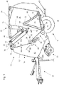
- FIG. 1 The drawing shows an embodiment of a press 10 is shown, which has a housing 12 supporting frame 14 which is supported on a chassis 16 on the ground 18.
- the press 10 shown is designed in the manner of a round baler and can be used both in the agricultural and in the industrial sector for the production of a round bale, in particular round cylindrical bale of harvested material, but also of waste, paper, fabric or tissue, cotton, tobacco etc. are used.
- Such a press 10 can be pulled by a work vehicle, not shown, preferably in the manner of a farm tractor, or be designed to be self-propelled.
- a drawbar 20 is provided at the front of the frame 14 to attach the press 10 to an agricultural tractor, not shown, and to be able to pull over a field.
- a pick-up device 22 in the form of a pick-up serves to receive crop material lying on the ground 18, e.g. of hay or straw deposited in a swath.
- the picked up by the receiving device 22 crop is fed to an inlet 24 a baling chamber 26 and rolled up there spirally to a round cylindrical bale, bound and then deposited on the substrate 18.
- the baling chamber 26 is further formed by an endless pressing means 34, which according to the present embodiment in the manner of two is carried out juxtaposed pressing belt and a number of stationary rollers 36, 38, 40, 42 and movable rollers 44, 42, 46, 48, 50, 52, 54, 56 is guided.
- the pressing means 34 has an outer side 34a facing the frame 14 and an inner side 34b.
- baling chamber 26 is circumferentially substantially surrounded by the pressing means 34 and the rollers 28, 30 and 32, it is bounded laterally by side walls, not shown.
- rollers 50, 52, 54, 56 of the movable rollers 44 - 56 are freely rotatably mounted in a lower portion 58 of a delta-shaped carrier 60 which is pivotally hinged about its upper tip 62 about a horizontally and transversely to the forward direction axis 64 and with an actuator (not shown) from the in Fig. 1 Bale formation position shown can be brought into a pivoted to the rear and top bale ejection position.
- a tensioning mechanism 66 for tightening the pressing means 34 has a tensioning lever 68, which cooperates with a first tensioning element (not shown), and a tensioning arm 72 cooperating with a second tensioning element 70.
- Both the clamping element, not shown, and the clamping element 72 may be formed in the usual way as a mechanical spring or as a hydraulic motor and / or have such.
- the tensioning lever 68 is mounted in the region of the side walls, not shown, about an axis 74 extending horizontally and transversely to the forward direction and carries two of the movable rollers 46, 48 and cleaning rollers 46a, 48a assigned to these rollers 46, 48 in an end region 76 facing away from the axis 74.
- the clamping arm 72 is mounted correspondingly about an axis 78 and carries in one end 80 one of the movable rollers 44.
- the clamping arm 68 is operatively connected to the clamping element 70 at one end, the other end with the press or their frame 14 in a manner not shown connected is.
- the pressing means 34 is always so firmly applied to the rotationally driven, stationary roller 38 by means of the clamping arm 70, that its entrainment is ensured.
- the roller 36 is driven in rotation.
- the pressing means 34 assumes an initial state in which it just straightens the inlet 24 bridges, and a final state in which it winds around a bale like a large loop.
- the baling chamber 26 is thus in Its size varies, ie its diameter increases with the size of the bale 18.
- the bale is in its formation in the baling chamber 26 and is largely wrapped by the pressing means 34, but falls from the baling chamber 26 to the rear on the ground 18, as soon as the carrier 60 with the movable rollers 50 - 56 opposite to the drawing swings upwards in a clockwise direction.
- the bale can also be stored on a press 10 downstream device.
- the illustrated embodiment of the baler is in the EP 1 308 078 A1 disclosed in detail.
- Other possible embodiments are in the DE 198 51 470 A1 .
- the disclosures of these documents are incorporated by reference into the present documentation.
- the press 10 in the manner of a so-called fixed-chamber press, the pressing means are preferably formed by substantially stationary rollers may be formed.
- a wrapping agent feed device 84 is provided which, in a known manner, brings wrapping means (not shown) to a bale formed in the baling chamber 26.
- wrapping means not shown
- the supply between the upper rollers 30 and 32 a housing or frame part of the Hüllatorizucht Anlagen 84 is shown by way of suggestion.
- a deflection device 88 is shown, which is provided to counteract an accumulation of material or crop, in particular in a region 90 between the housing or frame part 86 and the pressing means 34.
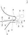
- the deflector 88 extends in the region 90 at least substantially across the width of the press 10, wherein the deflector 94 is connected to the frame 14 of the press 10 and extends away therefrom via retaining means 92 only shown by way of indication.
- the deflector device 88 is arranged between the pressing means 34 and a housing or frame part 86 of a wrapping agent feed device 84.
- the deflecting device is arranged such that non-pressed material emerging from the baling chamber 26 is at least partially intercepted by the deflecting device 88.
- the deflector 94 is formed at least partially in the manner of a movable or flexible flap.
- the deflector 94 is provided in one piece and is essentially formed by a rubber-like material applied to a textile carrier material, wherein the term rubber is not limited to natural rubber, but is intended to encompass any other suitable, in particular plastic material.
- Both in its holding means 92 to and facing away from the end portion 96 a, b of the deflector 94 forms a loop 98 which reinforces the respective end portion 96 a, b and can counteract a Auffaefing.
- the press 10 is moved by the unillustrated work vehicle over usually uneven ground.
- various components and / or work center of the press 10 are in motion.
- the receiving device 22 leads to the baling chamber 26 crop to form a bale.
- the pressing means 34 as shown in FIG. 1 and 2 set in motion (see arrow A). All this leads to vibrations of the press 10, by which the flexible deflector 94 is set in motion and, for example, depending on the strength and type of vibrations occurring and the exact design of the deflector 94, commutes, flutters and / or oscillates.
- the deflector 94 By the movement of the deflector 94 is a deposition of material, which can, for example, in difficult, especially dry harvesting conditions from the actual baling chamber 26, for example in the range of rollers 28 - 32 or rollers 36 - 56 can get into the surrounding housing 12, counteracts. In this way, a deposition and / or adhesion of material, in particular in areas around the housing or frame part 86 of the Hüllatorizucht Anlagen 84 can be counteracted.
Landscapes
- Life Sciences & Earth Sciences (AREA)
- Environmental Sciences (AREA)
- Engineering & Computer Science (AREA)
- Mechanical Engineering (AREA)
- Storage Of Harvested Produce (AREA)
- Harvesting Machines For Specific Crops (AREA)
Abstract
Description
- Die vorliegende Erfindung betrifft eine Abweisereinrichtung zur Verminderung von Materialansammlungen in einer Presse, welche vorzugsweise in der Art einer landwirtschaftlichen Rundballenpresse ausgebildet ist, eine Presse mit einer Abweisereinrichtung und ein Verfahren zum Betrieb einer Presse.
- Bekannte Abweisereinrichtungen werden an Pressen eingesetzt, um einer Ansammlung von Material innerhalb der Presse entgegenzuwirken und damit einem Verstopfen und/oder Blockieren der Presse bzw. einzelner oder mehrerer Arbeitsmittel der Presse vorzubeugen.
- Derartige Pressen werden sowohl im landwirtschaftlichen als auch im industriellen Bereich eingesetzt. Entsprechende landwirtschaftliche Pressen dienen beispielsweise zur Bildung von Erntegutballen, beispielsweise in der Art von Rundballen, und erzeugen häufig zumindest im Wesentlichen rundzylindrische Ballen aus Erntegut, beispielsweise in der Art von Stroh, Heu, Häckselgut etc.. Industrielle Pressen finden Verwendung bei der Verdichtung von Müll, Textilien oder anderen Stoffen bzw. bei deren Pressung zu Ballen.
- Es sind Abweisereinrichtungen bekannt, die Material von bestimmten Bereichen und/oder Arbeitsmitteln wie beispielsweise Pressmitteln in der Art von Gurten, Rollen bzw. Walzen weg lenken, um Ansammlungen von Material entgegenzuwirken. Derartige Abweisereinrichtung sind üblicherweise in der Art steifer Abdeckungen ausgebildet, welche insbesondere bei schwierigen Erntebedingungen, wie beispielsweise trockenem Erntegut, nicht optimal wirken.
- Die der Erfindung zugrunde liegende Aufgabe wird darin gesehen, eine Abweisereinrichtung, eine Presse und ein Verfahren der eingangs genannten Art anzugeben, durch welche die vorgenannten Nachteile überwunden werden.
- Die Aufgabe wird erfindungsgemäß durch die Lehre der Patentansprüche 1, 7 bzw. 9 gelöst. Weitere vorteilhafte Ausgestaltungen und Weiterbildungen der Erfindung gehen aus den Unteransprüchen hervor.
- Es ist eine Abweisereinrichtung zur Verminderung von Materialansammlungen in einer Presse vorgesehen, die wenigstens einen zumindest abschnittsweise beweglich ausgebildeten Abweiser aufweist. Dieser kann beispielsweise durch betriebsbedingte Vibrationen der Presse in Bewegung versetzt werden, wie sie beispielsweise durch eine Bewegung insbesondere mechanischer Arbeitsmittel bzw. Bauteile der Presse, wie etwa einer Aufnahmeeinrichtung, die Material bzw. Erntegut in einen Ballenpressraum einbringt, oder auch eines oder mehrerer Pressmittel, die oder das sich beweg(t)en, um in dem Ballenpressraum einen Ballen zu erzeugen, induziert werden, oder aber Auftreten, wenn die Presse einen insbesondere unebenen Untergrund überfährt. Der Abweiser kann beispielsweise derart ausgebildet sein, dass er schwingt, pendelt oder auch flattert, wodurch einem Ansammeln und/oder Ablagern bzw. Anhaften von Material in der näheren Umgebung des Abweisers vorgebeugt bzw. entgegengewirkt werden kann. Insbesondere kann der Abweiser flexibel, beispielsweise in sich biegsam ausgebildet sein.
- Der Abweiser kann einendends durch ein oder mehrere Haltemittel in vorteilhafter Weise direkt oder indirekt mit einem Rahmen der Presse verbindbar vorgesehen sein. Andernends kann der Abweiser vorzugsweise zumindest im Wesentlichen frei beweglich vorgesehen sein und/oder sich von dem/den Haltemittel(n) bzw. dem Rahmen weg erstrecken. Der Abweiser kann sich so beispielsweise, vorzugsweise wenigstens in einem Ruhezustand, zumindest im Wesentlichen vertikal nach unten erstrecken, es ist aber auch denkbar, dass er einen Winkel mit der Vertikalen einschließt.
- Besonders einfach und kostengünstig ist es, wenn der Abweiser einteilig ausgebildet ist. Eine einteilige Ausbildung kann darüber hinaus die Haltbarkeit des Abweisers verbessern. Auch kann der Abweiser lappenartig ausgebildet sein, so dass er im Wesentlichen frei in den Bereich der Presse hineinragen bzw. hängen kann, in dem einer Ansammlung von Material entgegengewirkt werden soll. Es ist aber auch denkbar, dass der Abweiser mehrteilig ausgebildet ist bzw. die Abweisereinrichtung mehrere Abweiser aufweist, beispielsweise um hierdurch ein von einer einteiligen Ausbildung abweichendes Bewegungsmuster zu erzielen.
- Es ist denkbar, dass der oder die Abweiser durch eine bzw. mehrere bewegliche Platte(n) gebildet wird/werden bzw. (eine) solche aufweist. Diese Platte(n) kann/können steif bzw. aus Metall, Hartplastik oder einem anderen steifen Werkstoff ausgebildet sein. Besonders vorteilhaft ist es aber, wenn der Abweiser zumindest bereichsweise aus einem elastischen und/oder gummiartigen Material besteht. Der Abweiser kann so auch in besonders einfacher Weise durch das/die Haltemittel gehalten werden, ohne dass hierzu eine gelenkige Verbindung notwendig ist. Eine verbesserte Haltbarkeit kann sich ergeben, wenn das verwendete Material eine textile Trägerschicht aufweist.
- Bildet der Abweiser zumindest in seinem Endbereich eine Schlaufe, so kann dies insbesondere bei der Verwendung eines textilen Trägermaterials einem Auffasern entgegenwirken. Durch eine derartige Schlaufe kann auch einem Ansammeln bzw. An-/Ablagern von Material weiter entgegengewirkt werden, insbesondere wenn dieser Bereich eine nicht nur flatternde sondern auch schlagende Wirkung erzielt. Es ist auch denkbar, an einem dem/n Haltemitteln zugewandten Bereich eine Schlaufe vorzusehen, welche optional auch als Befestigungsmöglichkeit oder zur Unterstützung einer Befestigung des Abweisers an dem Rahmen genutzt werden kann.
- Die Abweisereinrichtung kann an die jeweiligen Anforderungen angepasst angeordnet sein. Besonders günstig ist es aber, wenn die Abweisereinrichtung zumindest im Wesentlichen horizontal ausgerichtet ist, so dass eine möglichst freie Bewegung des bzw. der Abweiser möglich ist.
- Wird eine Presse mit einer oder mehreren der zuvor beschriebenen Abweisereinrichtungen ausgestattet, so kann dies die Funktion der Presse unterstützen, indem Ansammlungen von Material in der Presse bzw. in einem oder mehreren Bereichen der Presse vermindert und/oder verhindert werden können. Auf diese Weise kann Anhaftungen bzw. Ablagerungen von Material und/oder Verstopfungen der Presse und damit ungewollten Stillstandszeiten der Presse entgegengewirkt werden. Eine solche Presse weist üblicherweise ein Gehäuse und wenigstens ein in dem Gehäuse angeordnetes Pressmittel auf. Bei der Presse handelt es sich insbesondere um eine landwirtschaftliche Ballenpresse zur Bildung rundzylindrischer Ballen. Die Presse kann aber auch im industriellen Bereich, beispielsweise zur Bildung von Ballen aus Papier, Müll, Stoff oder anderen Materialien eingesetzt werden.
- Die Abweisereinrichtung kann in jedem Bereich der Presse, in der es zu Ansammlungen von Material kommen kann, angeordnet sein. Besonders vorteilhaft ist es aber, wenigstens eine solche Abweisereinrichtung zwischen dem Pressmittel und dem Gehäuse und vorzugsweise angrenzend und/oder oberhalb einer Hüllmittelzufuhreinrichtung anzuordnen.
- Gemäß einem Verfahren zum Betrieb einer Ballenpresse wird die Abweisereinrichtung während der Bildung eines Ballen durch im Betrieb der Presse auftretende Vibrationen derart beeinflusst, dass der Abweiser in Bewegung, vorzugsweise in Schwingung, Pendeln bzw. Flattern, versetzt wird, wodurch der Abweiser einer Ansammlung von Material entgegenwirken kann.
- Anhand der Zeichnung, die ein Ausführungsbeispiel der Erfindung zeigt, werden nachfolgend die Erfindung sowie weitere Vorteile und vorteilhafte Weiterbildungen der Erfindung und Ausgestaltungen der Erfindung näher beschrieben und erläutert.
- Es zeigt:
- Fig. 1
- eine Presse in Seitenansicht mit einer Abweisereinrichtung und
- Fig. 2
- eine vergrößerte Darstellung der Abweisereinrichtung.
- In der
Fig. 1 der Zeichnung ist eine Ausführungsform einer Presse 10 dargestellt, die einen ein Gehäuse 12 tragenden Rahmen 14 aufweist, der sich über ein Fahrwerk 16 auf dem Untergrund 18 abstützt. Die gezeigte Presse 10 ist in der Art einer Rundballenpresse ausgebildet und kann sowohl im landwirtschaftlichen als auch im industriellen Bereich zur Herstellung eines üblicherweise als Rundballen bezeichneten, insbesondere rundzylindrischen Ballens aus Erntegut, aber auch aus Müll, Papier, Stoff bzw. Gewebe, Baumwolle, Tabak etc. eingesetzt werden. Eine solche Presse 10 kann von einem nicht gezeigten Arbeitsfahrzeug, vorzugsweise in der Art eines Ackerschleppers, gezogen werden oder auch selbstfahrend ausgebildet sein. - Gemäß dem vorliegenden Ausführungsbeispiel ist an der Vorderseite des Rahmens 14 eine Deichsel 20 vorgesehen, um die Presse 10 an einem nicht gezeigten Ackerschlepper anhängen und über ein Feld ziehen zu können. Eine Aufnahmevorrichtung 22 in Form einer Pick-Up dient zur Aufnahme von auf dem Untergrund 18 liegenden Erntegut, z.B. von in einem Schwad abgelegten Heu oder Stroh. Das von der Aufnahmevorrichtung 22 aufgenommene Erntegut wird einem Einlass 24 einem Ballenpressraums 26 zugeführt und dort spiralförmig zu einem rundzylindrischen Ballen aufgerollt, gebunden und anschließend auf dem Untergrund 18 abgelegt.
- Am Einlass 24 des Ballenpressraums 26 sind eine untere, stationäre Rolle 28 und zwei obere Rollen 30, 32 positioniert. Der Ballenpressraum 26 wird weiterhin durch ein endloses Pressmittel 34 gebildet, das gemäß der vorliegenden Ausführungsform in der Art zweier nebeneinander anliegender Pressriemen ausgeführt ist und um eine Anzahl von ortsfesten Walzen 36, 38, 40, 42 und bewegbaren Walzen 44 , 42, 46, 48, 50, 52, 54, 56 geführt wird. Das Pressmittel 34 weist eine dem Rahmen 14 zugewandte Außenseite 34a und eine Innenseite 34b auf.
- Während der Ballenpressraum 26 umfangsseitig im Wesentlichen von dem Pressmittel 34 und den Rollen 28, 30 und 32 umgeben wird, wird er seitlich von nicht gezeigten Seitenwänden begrenzt.
- Vier Walzen 50, 52, 54, 56 der bewegbaren Walzen 44 - 56 sind in einem unteren Bereich 58 eines deltaförmigen Trägers 60 frei drehbar gelagert, der um seine obere Spitze 62 um eine horizontal und quer zur Vorwärtsrichtung verlaufende Achse 64 schwenkbar angelenkt ist und mit einem Aktor (nicht gezeigt) aus der in
Fig. 1 dargestellten Ballenbildungsposition in eine nach hinten und oben verschwenkte Ballenauswurfposition verbringbar ist. - Ein Spannmechanismus 66 zur Straffung des Pressmittels 34 weist einen Spannhebel 68, der mit einem nicht gezeigten ersten Spannelement zusammenwirkt, und einen mit einem zweiten Spannelement 70 zusammenwirkenden Spannarm 72 auf. Sowohl das nicht gezeigte Spannelement als auch das Spannelement 72 kann in üblicher Weise als eine mechanische Feder oder als ein Hydraulikmotor ausgebildet sein und/oder einen solchen aufweisen.
- Der Spannhebel 68 ist im Bereich der nicht gezeigten Seitenwände um eine horizontal und quer zur Vorwärtsrichtung verlaufende Achse 74 gelagert und trägt in einem der Achse 74 abgewandten Endbereich 76 zwei der bewegbaren Rollen 46, 48 sowie diesen Rollen 46, 48 zugeordnete Reinigungsrollen 46a, 48a. Der Spannarm 72 ist entsprechend um eine Achse 78 gelagert und trägt in einem Endbereich 80 eine der bewegbaren Rollen 44. Darüber hinaus ist der Spannarm 68 mit dem Spannelement 70 einenends wirksam verbunden, das andernends mit der Presse bzw. deren Rahmen 14 in nicht gezeigter Weise verbunden ist.
- Das Pressmittel 34 wird mittels des Spannarms 70 stets so fest an die drehend angetriebene, ortsfeste Walze 38 angelegt, dass seine Mitnahme gewährleistet ist. Auch die Walze 36 wird drehend angetrieben. Das Pressmittel 34 nimmt einen Anfangszustand ein, in dem es gerade gestreckt den Einlass 24 überbrückt, und einen Endzustand, in dem es sich wie eine große Schlaufe um einen Ballen schlingt. Der Ballenpressraum 26 ist somit in seiner Größe veränderlich, d. h. sein Durchmesser nimmt mit der Größe des Ballens 18 zu. Der Ballen befindet sich während seiner Bildung in dem Ballenpressraum 26 und wird von dem Pressmittel 34 größtenteils umschlungen, fällt aber aus dem Ballenpressraum 26 nach hinten auf den Untergrund 18, sobald der Träger 60 mit den beweglichen Walzen 50 - 56 mit Blick auf die Zeichnung entgegen dem Uhrzeigerdrehsinn nach oben schwenkt. Alternativ kann der Ballen auch auf einem der Presse 10 nachgeordneten Gerät abgelegt werden.
- Die dargestellte Ausführungsform der Ballenpresse ist in der
EP 1 308 078 A1 detailliert offenbart. Andere, mögliche Ausführungsformen sind in derDE 198 51 470 A1 ,DE 102 41 215 A1 und derEP 1 264 531 A1 beschrieben. Die Offenbarungen dieser Dokumente werden durch Verweis mit in die vorliegenden Unterlagen aufgenommen. Es ist aber auch denkbar, dass die Presse 10 in der Art einer sogenannten Festkammerpresse, deren Pressmittel vorzugsweise durch im Wesentlichen stationärer Rollen gebildet werden, ausgebildet sein kann. - In einem der Deichsel 20 zugewandten Bereich 82 der Ballenpresse 10 ist darüber hinaus eine Hüllmittelzufuhreinrichtungen 84 vorgesehen, die in bekannter Art und Weise Hüllmittel (nicht gezeigt) an einen in dem Ballenpressraum 26 gebildeten Ballen heranführt. Gemäß dem vorliegenden Ausführungsbeispiel erfolgt die Zufuhr zwischen den oberen Rollen 30 und 32. Bei 86 ist ein Gehäuse- oder Rahmenteil der Hüllmittelzufuhreinrichtung 84 andeutungsweise dargestellt. Angrenzend an den Gehäuse- oder Rahmenteil 86 wird eine Abweisereinrichtung 88 gezeigt, die vorgesehen ist, um einer Ansammlung von Material bzw. Erntegut insbesondere in einem Bereich 90 zwischen dem Gehäuse- oder Rahmenteil 86 und dem Pressemittel 34 entgegenzuwirken.
- Es wird nun auch auf die
Figur 2 der Zeichnung Bezug genommen, in der die Abweisereinrichtung 88 in einer vergrößertenr Darstellung gezeigt wird. Die Abweisereinrichtung 88 erstreckt sich in dem Bereich 90 zumindest im Wesentlichen über die Breite der Presse 10, wobei der Abweiser 94 über nur andeutungsweise dargestellte Haltemittel 92 mit dem Rahmen 14 der Presse 10 verbunden ist und sich von diesem weg erstreckt. Die Abweisereinrichtung 88 ist zwischen dem Pressmittel 34 und einem Gehäuse- oder Rahmenteil 86 einer Hüllmittelzufuhreinrichtung 84 angeordnet. Vorzugsweise ist die Abweisereinrichtung derart angeordnet, dass aus dem Ballenpressraum 26 heraustretendes, nicht gepresstes Material zumindest teilweise von der Abweisereinrichtung 88 abgefangen wird. Damit wird das aus dem Ballenpressraum heraustretende Material davon abgehalten in einen vorderen Bereich der Ballenpresse, insbesondere in einen Bereich der Hüllmittelzufuhreinrichtung 84 zu gelangen, um sich dort festzusetzen. Es ist vielmehr vorgesehen, dass das von der Abweisereinrichtung 88 abgefangene Material ohne Materialanhäufungen abprallt und in Richtung Aufnahmevorrichtung 22 herunterfällt. - Der Abweiser 94 ist zumindest bereichsweise in der Art eines beweglichen bzw. flexiblen Lappens ausgebildet. Gemäß dem gezeigten Ausführungsbeispiel ist der Abweiser 94 einteilig vorgesehen und wird im Wesentlichen durch ein auf ein textiles Trägermaterial aufgebrachtes, gummiartiges Material gebildet, wobei der Begriff Gummi nicht auf Naturkautschuk beschränkt ist, sondern jedes andere, geeignete, insbesondere Kunststoffmaterial umfassen soll. Sowohl in seinem den Haltemitteln 92 zu als auch abgewandten Endbereich 96 a, b bildet der Abweiser 94 eine Schlaufe 98, die den jeweiligen Endbereich 96 a, b verstärkt und einem Auffasern entgegenwirken kann.
- Im Betrieb wird die Presse 10 durch das nicht dargestelltes Arbeitsfahrzeug über üblicherweise unebenen Untergrund bewegt. Darüber hinaus befinden sich diverse Bauteile und/oder Arbeitsmitte der Presse 10 in Bewegung. So führt beispielsweise die Aufnahmevorrichtung 22 dem Ballenpressraum 26 Erntegut zur Bildung eines Ballens zu. Darüber hinaus wird beispielsweise das Pressmittel 34 gemäß der Darstellung in
Figur 1 und2 in Bewegung versetzt (siehe Pfeil A). All dies führt zu Vibrationen der Presse 10, durch welche der flexible Abweiser 94 in Bewegung versetzt wird und beispielsweise, je nach Stärke und Art der auftretenden Vibrationen und der genauen Ausführung des Abweisers 94, pendelt, flattert und/oder schwingt. Durch die Bewegung des Abweisers 94 wird einer Ablagerung von Material, welches beispielsweise bei schwierigen, insbesondere trockenen Erntebedingungen aus dem eigentlichen Ballenpressraum 26 beispielsweise im Bereich der Rollen 28 - 32 bzw. Walzen 36 - 56 in das umliegende Gehäuse 12 gelangen kann, entgegenwirkt. Auf dies Weise kann einer Ablagerungen und/oder Anhaftung von Material insbesondere in Bereichen um den Gehäuse- oder Rahmenteil 86 der Hüllmittelzufuhreinrichtung 84 entgegengewirkt werden.
Claims (10)
- Abweisereinrichtung (88) zur Verminderung von Materialansammlungen in einer Presse (10), welche vorzugsweise in der Art einer landwirtschaftlichen Rundballenpresse ausgebildet ist, dadurch gekennzeichnet, dass die Abweisereinrichtung (88) wenigstens einen zumindest abschnittsweise beweglich, flexibel ausgebildeten Abweiser (94) aufweist.
- Abweisereinrichtung (88) nach Anspruch 1, dadurch gekennzeichnet, der Abweiser (94) einenends durch wenigstens ein Haltemittel (92) mit einem Rahmenteil (14) der Presse (10) verbindbar vorgesehen ist und sich andernends im Wesentlichen frei beweglich erstreckt.
- Abweisereinrichtung (88) nach Anspruch 1 oder 2, dadurch gekennzeichnet, dass der Abweiser (94) zumindest im Wesentlichen einteilig ausgebildet ist.
- Abweisereinrichtung (88) nach einem der vorherigen Ansprüche, dadurch gekennzeichnet, dass der Abweiser (94) zumindest bereichsweise aus einem elastischen und/oder gummiartigen, eine textile Trägerschicht aufweisenden Material besteht.
- Abweisereinrichtung (88) nach Anspruch 4, dadurch gekennzeichnet, dass der Abweiser (94) zumindest in einem seiner Endbereiche (96 a, b) eine Schlaufe (98) bildet.
- Abweisereinrichtung (88) nach einem der vorherigen Ansprüche, dadurch gekennzeichnet, dass sich die Abweisereinrichtung (88) zumindest im Wesentlichen horizontal erstreckt.
- Presse (10), insbesondere eine landwirtschaftliche Ballenpresse zur Bildung rundzylindrischer Ballen, mit einem Gehäuse (12), wenigstens einem in dem Gehäuse (12) angeordneten und einen Ballenpressraum (26) bildenden Pressmittel (34) und mit einer Abweisereinrichtung (88) nach einem der vorherigen Ansprüche.
- Presse nach Anspruch 7, dadurch gekennzeichnet, dass die Abweisereinrichtung (88) zwischen dem Pressmittel (34) und einem Gehäuse- oder Rahmenteil (86) einer Hüllmittelzufuhreinrichtung (84) angeordent ist.
- Presse nach Anspruch 7 oder 8, dadurch gekennzeichnet, dass die Abweisereinrichtung (88) derart angeordnet ist, dass aus dem Ballenpressraum (26) heraustretendes, nicht gepresstes Material zumindest teilweise von der Abweisereinrichtung (88) abgefangen wird.
- Verfahren zum Betrieb einer Presse (10) nach einem der Ansprüche 7 bis 9, dadurch gekennzeichnet, dass die Abweisereinrichtung (88) während der Bildung eines Ballen durch im Betrieb der Presse (10) auftretende Vibrationen derart beeinflusst wird, dass der Abweiser (94) in Bewegung, vorzugsweise in Schwingung, Pendeln bzw. Flattern, versetzt wird, so dass einer Ansammlung von Material entgegengewirkt wird.
Applications Claiming Priority (1)
| Application Number | Priority Date | Filing Date | Title |
|---|---|---|---|
| DE102017208761.7A DE102017208761A1 (de) | 2017-05-23 | 2017-05-23 | Abweisereinrichtung, Presse und Verfahren |
Publications (2)
| Publication Number | Publication Date |
|---|---|
| EP3406132A1 true EP3406132A1 (de) | 2018-11-28 |
| EP3406132B1 EP3406132B1 (de) | 2020-10-07 |
Family
ID=62110903
Family Applications (1)
| Application Number | Title | Priority Date | Filing Date |
|---|---|---|---|
| EP18170400.8A Active EP3406132B1 (de) | 2017-05-23 | 2018-05-02 | Abweisereinrichtung, presse und verfahren |
Country Status (4)
| Country | Link |
|---|---|
| US (1) | US20180338427A1 (de) |
| EP (1) | EP3406132B1 (de) |
| CN (1) | CN108928030A (de) |
| DE (1) | DE102017208761A1 (de) |
Cited By (1)
| Publication number | Priority date | Publication date | Assignee | Title |
|---|---|---|---|---|
| EP3714670A1 (de) * | 2019-03-29 | 2020-09-30 | Maschinenfabrik Bernard Krone GmbH & Co. KG | Landwirtschaftliche runballenpresse |
Citations (10)
| Publication number | Priority date | Publication date | Assignee | Title |
|---|---|---|---|---|
| GB2084094A (en) * | 1980-09-11 | 1982-04-07 | Typrod Ltd | A spray reducing device for a vehicle |
| EP0095688A1 (de) * | 1982-05-28 | 1983-12-07 | Deere & Company | Rundballenpresse mit einem einen Guteinlass aufweisenden Ballenpressraum |
| DE8325223U1 (de) * | 1983-09-02 | 1986-02-06 | Claas Ohg, 4834 Harsewinkel | Großballenpresse für landwirtschaftliches Erntegut |
| DE19851470A1 (de) | 1998-11-09 | 2000-05-11 | Lely Welger Maschinenfabrik | Rundballenpresse für landwirtschaftliches Erntegut |
| EP1264531A1 (de) | 2001-06-06 | 2002-12-11 | Deere & Company | Rundballenpresse |
| EP1308078A1 (de) | 2001-10-30 | 2003-05-07 | Deere & Company | Rundballenpresse |
| DE10241215A1 (de) | 2002-09-06 | 2004-03-18 | Deere & Company, Moline | Rundballenpresse mit Wägeeinrichtung |
| DE202005018518U1 (de) * | 2005-11-26 | 2006-01-19 | Deere & Company, Moline | Ballenpresse |
| EP1648217A2 (de) * | 2003-07-31 | 2006-04-26 | Kverneland Group Geldrop B.V. | Abdeckfolienzufuhrvorrichtung zur abdeckung der aussenfläche eines landwirtschaftlichen ballens |
| US9434419B1 (en) * | 2012-12-10 | 2016-09-06 | Clarence Russell Casto, Jr. | Flexible flap assembly for a vehicle and kit containing the same |
Family Cites Families (8)
| Publication number | Priority date | Publication date | Assignee | Title |
|---|---|---|---|---|
| US3125948A (en) * | 1964-03-24 | Cleaner bar for upper baler drive roller | ||
| JP3222201B2 (ja) * | 1992-06-08 | 2001-10-22 | 株式会社デュプロ | 紙折機 |
| US5913805A (en) * | 1997-07-11 | 1999-06-22 | New Holland North America, Inc. | Trash baffle for round baler apparatus |
| US6016645A (en) * | 1998-05-11 | 2000-01-25 | Voss; Donald | Windrow deflector plate for a round baler |
| US6098390A (en) * | 1998-11-03 | 2000-08-08 | Deere & Company | Round baler belt support roll constructed for deflecting crop material away from roll clearance gaps in baling chamber side walls |
| GB201312758D0 (en) * | 2013-07-17 | 2013-08-28 | Kuhn Geldrop Bv | Baler |
| CN104170580B (zh) * | 2014-08-15 | 2016-01-27 | 江苏大学 | 一种联合收割打捆机防堵塞装置 |
| CN105103817B (zh) * | 2015-08-21 | 2017-06-13 | 牡丹江市万通微孔技术开发有限责任公司 | 一种圆捆打捆机 |
-
2017
- 2017-05-23 DE DE102017208761.7A patent/DE102017208761A1/de not_active Withdrawn
-
2018
- 2018-04-20 CN CN201810360068.9A patent/CN108928030A/zh active Pending
- 2018-05-02 EP EP18170400.8A patent/EP3406132B1/de active Active
- 2018-05-10 US US15/976,068 patent/US20180338427A1/en not_active Abandoned
Patent Citations (10)
| Publication number | Priority date | Publication date | Assignee | Title |
|---|---|---|---|---|
| GB2084094A (en) * | 1980-09-11 | 1982-04-07 | Typrod Ltd | A spray reducing device for a vehicle |
| EP0095688A1 (de) * | 1982-05-28 | 1983-12-07 | Deere & Company | Rundballenpresse mit einem einen Guteinlass aufweisenden Ballenpressraum |
| DE8325223U1 (de) * | 1983-09-02 | 1986-02-06 | Claas Ohg, 4834 Harsewinkel | Großballenpresse für landwirtschaftliches Erntegut |
| DE19851470A1 (de) | 1998-11-09 | 2000-05-11 | Lely Welger Maschinenfabrik | Rundballenpresse für landwirtschaftliches Erntegut |
| EP1264531A1 (de) | 2001-06-06 | 2002-12-11 | Deere & Company | Rundballenpresse |
| EP1308078A1 (de) | 2001-10-30 | 2003-05-07 | Deere & Company | Rundballenpresse |
| DE10241215A1 (de) | 2002-09-06 | 2004-03-18 | Deere & Company, Moline | Rundballenpresse mit Wägeeinrichtung |
| EP1648217A2 (de) * | 2003-07-31 | 2006-04-26 | Kverneland Group Geldrop B.V. | Abdeckfolienzufuhrvorrichtung zur abdeckung der aussenfläche eines landwirtschaftlichen ballens |
| DE202005018518U1 (de) * | 2005-11-26 | 2006-01-19 | Deere & Company, Moline | Ballenpresse |
| US9434419B1 (en) * | 2012-12-10 | 2016-09-06 | Clarence Russell Casto, Jr. | Flexible flap assembly for a vehicle and kit containing the same |
Cited By (1)
| Publication number | Priority date | Publication date | Assignee | Title |
|---|---|---|---|---|
| EP3714670A1 (de) * | 2019-03-29 | 2020-09-30 | Maschinenfabrik Bernard Krone GmbH & Co. KG | Landwirtschaftliche runballenpresse |
Also Published As
| Publication number | Publication date |
|---|---|
| EP3406132B1 (de) | 2020-10-07 |
| DE102017208761A1 (de) | 2018-11-29 |
| US20180338427A1 (en) | 2018-11-29 |
| CN108928030A (zh) | 2018-12-04 |
Similar Documents
| Publication | Publication Date | Title |
|---|---|---|
| EP3222134B1 (de) | Rundballenpresse und verfahren | |
| EP1252813B2 (de) | Landwirtschaftliche Erntemaschine | |
| EP1932419B1 (de) | Landwirtschaftliche Presse | |
| EP4108069A1 (de) | Rundballenpresse | |
| EP1790206A1 (de) | Aufsammeleinrichtung für landwirtschaftliche Erntemaschinen | |
| DE10255175A1 (de) | Ballenpresse | |
| EP0499909A1 (de) | Rundballenpresse | |
| EP1557080B1 (de) | Ballenpresse | |
| DE19950750A1 (de) | Schneidvorrichtung einer landwirtschaftlichen Erntebergungsmaschine | |
| EP3315015B1 (de) | Rundballenpresse, kombination eines landwirtschaftlichen fahrzeugs mit einer solchen und verfahren zum pressen von rundballen | |
| DE10251827A1 (de) | Gutaufnehmer | |
| EP1169907A1 (de) | Reversiervorrichtung für Landwirtschaftliche Erntemaschine | |
| EP3569056B1 (de) | Pressmittelleiteinrichtung und presse | |
| EP3482625B1 (de) | Leiteinrichtung und ballenpresse | |
| EP3406132B1 (de) | Abweisereinrichtung, presse und verfahren | |
| EP3501261B1 (de) | Leitmittel, ballenpresse und verfahren | |
| DE10249595A1 (de) | Erntebergungsmaschine | |
| EP4074162B1 (de) | Rundballenpresse mit starterwalze und elastisch auslenkbarem auslenkelement | |
| EP1738634B1 (de) | Erntegutaufnahmeeinrichtung und Erntemaschine | |
| EP0095689A1 (de) | Rundballenpresse mit einem einen Guteinlass aufweisenden Ballenpressraum | |
| EP4309491B1 (de) | Rundballenpresse | |
| EP3420805B1 (de) | Umhüllungseinrichtung, blockiereinrichtung, ballenpresse und verfahren zur anpassung einer ballenpresse an ein hüllmaterial | |
| DE4113630A1 (de) | Aufbereitungsmaschine fuer halmgut | |
| DE102005062249A1 (de) | Überkopfförderer | |
| EP1413191A1 (de) | Presse |
Legal Events
| Date | Code | Title | Description |
|---|---|---|---|
| PUAI | Public reference made under article 153(3) epc to a published international application that has entered the european phase |
Free format text: ORIGINAL CODE: 0009012 |
|
| STAA | Information on the status of an ep patent application or granted ep patent |
Free format text: STATUS: THE APPLICATION HAS BEEN PUBLISHED |
|
| AK | Designated contracting states |
Kind code of ref document: A1 Designated state(s): AL AT BE BG CH CY CZ DE DK EE ES FI FR GB GR HR HU IE IS IT LI LT LU LV MC MK MT NL NO PL PT RO RS SE SI SK SM TR |
|
| AX | Request for extension of the european patent |
Extension state: BA ME |
|
| STAA | Information on the status of an ep patent application or granted ep patent |
Free format text: STATUS: REQUEST FOR EXAMINATION WAS MADE |
|
| 17P | Request for examination filed |
Effective date: 20190528 |
|
| RBV | Designated contracting states (corrected) |
Designated state(s): AL AT BE BG CH CY CZ DE DK EE ES FI FR GB GR HR HU IE IS IT LI LT LU LV MC MK MT NL NO PL PT RO RS SE SI SK SM TR |
|
| STAA | Information on the status of an ep patent application or granted ep patent |
Free format text: STATUS: EXAMINATION IS IN PROGRESS |
|
| 17Q | First examination report despatched |
Effective date: 20191028 |
|
| GRAP | Despatch of communication of intention to grant a patent |
Free format text: ORIGINAL CODE: EPIDOSNIGR1 |
|
| STAA | Information on the status of an ep patent application or granted ep patent |
Free format text: STATUS: GRANT OF PATENT IS INTENDED |
|
| INTG | Intention to grant announced |
Effective date: 20200525 |
|
| GRAS | Grant fee paid |
Free format text: ORIGINAL CODE: EPIDOSNIGR3 |
|
| GRAA | (expected) grant |
Free format text: ORIGINAL CODE: 0009210 |
|
| STAA | Information on the status of an ep patent application or granted ep patent |
Free format text: STATUS: THE PATENT HAS BEEN GRANTED |
|
| AK | Designated contracting states |
Kind code of ref document: B1 Designated state(s): AL AT BE BG CH CY CZ DE DK EE ES FI FR GB GR HR HU IE IS IT LI LT LU LV MC MK MT NL NO PL PT RO RS SE SI SK SM TR |
|
| REG | Reference to a national code |
Ref country code: GB Ref legal event code: FG4D Free format text: NOT ENGLISH |
|
| REG | Reference to a national code |
Ref country code: CH Ref legal event code: EP Ref country code: AT Ref legal event code: REF Ref document number: 1320175 Country of ref document: AT Kind code of ref document: T Effective date: 20201015 |
|
| REG | Reference to a national code |
Ref country code: IE Ref legal event code: FG4D Free format text: LANGUAGE OF EP DOCUMENT: GERMAN |
|
| REG | Reference to a national code |
Ref country code: DE Ref legal event code: R096 Ref document number: 502018002650 Country of ref document: DE |
|
| REG | Reference to a national code |
Ref country code: NL Ref legal event code: MP Effective date: 20201007 |
|
| PG25 | Lapsed in a contracting state [announced via postgrant information from national office to epo] |
Ref country code: RS Free format text: LAPSE BECAUSE OF FAILURE TO SUBMIT A TRANSLATION OF THE DESCRIPTION OR TO PAY THE FEE WITHIN THE PRESCRIBED TIME-LIMIT Effective date: 20201007 Ref country code: PT Free format text: LAPSE BECAUSE OF FAILURE TO SUBMIT A TRANSLATION OF THE DESCRIPTION OR TO PAY THE FEE WITHIN THE PRESCRIBED TIME-LIMIT Effective date: 20210208 Ref country code: FI Free format text: LAPSE BECAUSE OF FAILURE TO SUBMIT A TRANSLATION OF THE DESCRIPTION OR TO PAY THE FEE WITHIN THE PRESCRIBED TIME-LIMIT Effective date: 20201007 Ref country code: NO Free format text: LAPSE BECAUSE OF FAILURE TO SUBMIT A TRANSLATION OF THE DESCRIPTION OR TO PAY THE FEE WITHIN THE PRESCRIBED TIME-LIMIT Effective date: 20210107 Ref country code: GR Free format text: LAPSE BECAUSE OF FAILURE TO SUBMIT A TRANSLATION OF THE DESCRIPTION OR TO PAY THE FEE WITHIN THE PRESCRIBED TIME-LIMIT Effective date: 20210108 |
|
| REG | Reference to a national code |
Ref country code: LT Ref legal event code: MG4D |
|
| PG25 | Lapsed in a contracting state [announced via postgrant information from national office to epo] |
Ref country code: PL Free format text: LAPSE BECAUSE OF FAILURE TO SUBMIT A TRANSLATION OF THE DESCRIPTION OR TO PAY THE FEE WITHIN THE PRESCRIBED TIME-LIMIT Effective date: 20201007 Ref country code: IS Free format text: LAPSE BECAUSE OF FAILURE TO SUBMIT A TRANSLATION OF THE DESCRIPTION OR TO PAY THE FEE WITHIN THE PRESCRIBED TIME-LIMIT Effective date: 20210207 Ref country code: LV Free format text: LAPSE BECAUSE OF FAILURE TO SUBMIT A TRANSLATION OF THE DESCRIPTION OR TO PAY THE FEE WITHIN THE PRESCRIBED TIME-LIMIT Effective date: 20201007 Ref country code: SE Free format text: LAPSE BECAUSE OF FAILURE TO SUBMIT A TRANSLATION OF THE DESCRIPTION OR TO PAY THE FEE WITHIN THE PRESCRIBED TIME-LIMIT Effective date: 20201007 Ref country code: BG Free format text: LAPSE BECAUSE OF FAILURE TO SUBMIT A TRANSLATION OF THE DESCRIPTION OR TO PAY THE FEE WITHIN THE PRESCRIBED TIME-LIMIT Effective date: 20210107 Ref country code: ES Free format text: LAPSE BECAUSE OF FAILURE TO SUBMIT A TRANSLATION OF THE DESCRIPTION OR TO PAY THE FEE WITHIN THE PRESCRIBED TIME-LIMIT Effective date: 20201007 |
|
| PG25 | Lapsed in a contracting state [announced via postgrant information from national office to epo] |
Ref country code: HR Free format text: LAPSE BECAUSE OF FAILURE TO SUBMIT A TRANSLATION OF THE DESCRIPTION OR TO PAY THE FEE WITHIN THE PRESCRIBED TIME-LIMIT Effective date: 20201007 Ref country code: NL Free format text: LAPSE BECAUSE OF FAILURE TO SUBMIT A TRANSLATION OF THE DESCRIPTION OR TO PAY THE FEE WITHIN THE PRESCRIBED TIME-LIMIT Effective date: 20201007 |
|
| REG | Reference to a national code |
Ref country code: DE Ref legal event code: R097 Ref document number: 502018002650 Country of ref document: DE |
|
| PG25 | Lapsed in a contracting state [announced via postgrant information from national office to epo] |
Ref country code: LT Free format text: LAPSE BECAUSE OF FAILURE TO SUBMIT A TRANSLATION OF THE DESCRIPTION OR TO PAY THE FEE WITHIN THE PRESCRIBED TIME-LIMIT Effective date: 20201007 Ref country code: RO Free format text: LAPSE BECAUSE OF FAILURE TO SUBMIT A TRANSLATION OF THE DESCRIPTION OR TO PAY THE FEE WITHIN THE PRESCRIBED TIME-LIMIT Effective date: 20201007 Ref country code: SK Free format text: LAPSE BECAUSE OF FAILURE TO SUBMIT A TRANSLATION OF THE DESCRIPTION OR TO PAY THE FEE WITHIN THE PRESCRIBED TIME-LIMIT Effective date: 20201007 Ref country code: EE Free format text: LAPSE BECAUSE OF FAILURE TO SUBMIT A TRANSLATION OF THE DESCRIPTION OR TO PAY THE FEE WITHIN THE PRESCRIBED TIME-LIMIT Effective date: 20201007 Ref country code: CZ Free format text: LAPSE BECAUSE OF FAILURE TO SUBMIT A TRANSLATION OF THE DESCRIPTION OR TO PAY THE FEE WITHIN THE PRESCRIBED TIME-LIMIT Effective date: 20201007 Ref country code: SM Free format text: LAPSE BECAUSE OF FAILURE TO SUBMIT A TRANSLATION OF THE DESCRIPTION OR TO PAY THE FEE WITHIN THE PRESCRIBED TIME-LIMIT Effective date: 20201007 |
|
| PLBE | No opposition filed within time limit |
Free format text: ORIGINAL CODE: 0009261 |
|
| STAA | Information on the status of an ep patent application or granted ep patent |
Free format text: STATUS: NO OPPOSITION FILED WITHIN TIME LIMIT |
|
| PG25 | Lapsed in a contracting state [announced via postgrant information from national office to epo] |
Ref country code: DK Free format text: LAPSE BECAUSE OF FAILURE TO SUBMIT A TRANSLATION OF THE DESCRIPTION OR TO PAY THE FEE WITHIN THE PRESCRIBED TIME-LIMIT Effective date: 20201007 |
|
| 26N | No opposition filed |
Effective date: 20210708 |
|
| PG25 | Lapsed in a contracting state [announced via postgrant information from national office to epo] |
Ref country code: AL Free format text: LAPSE BECAUSE OF FAILURE TO SUBMIT A TRANSLATION OF THE DESCRIPTION OR TO PAY THE FEE WITHIN THE PRESCRIBED TIME-LIMIT Effective date: 20201007 Ref country code: IT Free format text: LAPSE BECAUSE OF FAILURE TO SUBMIT A TRANSLATION OF THE DESCRIPTION OR TO PAY THE FEE WITHIN THE PRESCRIBED TIME-LIMIT Effective date: 20201007 |
|
| PG25 | Lapsed in a contracting state [announced via postgrant information from national office to epo] |
Ref country code: SI Free format text: LAPSE BECAUSE OF FAILURE TO SUBMIT A TRANSLATION OF THE DESCRIPTION OR TO PAY THE FEE WITHIN THE PRESCRIBED TIME-LIMIT Effective date: 20201007 |
|
| REG | Reference to a national code |
Ref country code: CH Ref legal event code: PL |
|
| PG25 | Lapsed in a contracting state [announced via postgrant information from national office to epo] |
Ref country code: CH Free format text: LAPSE BECAUSE OF NON-PAYMENT OF DUE FEES Effective date: 20210531 Ref country code: LU Free format text: LAPSE BECAUSE OF NON-PAYMENT OF DUE FEES Effective date: 20210502 Ref country code: MC Free format text: LAPSE BECAUSE OF FAILURE TO SUBMIT A TRANSLATION OF THE DESCRIPTION OR TO PAY THE FEE WITHIN THE PRESCRIBED TIME-LIMIT Effective date: 20201007 Ref country code: LI Free format text: LAPSE BECAUSE OF NON-PAYMENT OF DUE FEES Effective date: 20210531 |
|
| REG | Reference to a national code |
Ref country code: BE Ref legal event code: MM Effective date: 20210531 |
|
| PG25 | Lapsed in a contracting state [announced via postgrant information from national office to epo] |
Ref country code: IE Free format text: LAPSE BECAUSE OF NON-PAYMENT OF DUE FEES Effective date: 20210502 |
|
| PG25 | Lapsed in a contracting state [announced via postgrant information from national office to epo] |
Ref country code: IS Free format text: LAPSE BECAUSE OF FAILURE TO SUBMIT A TRANSLATION OF THE DESCRIPTION OR TO PAY THE FEE WITHIN THE PRESCRIBED TIME-LIMIT Effective date: 20210207 |
|
| PG25 | Lapsed in a contracting state [announced via postgrant information from national office to epo] |
Ref country code: BE Free format text: LAPSE BECAUSE OF NON-PAYMENT OF DUE FEES Effective date: 20210531 |
|
| GBPC | Gb: european patent ceased through non-payment of renewal fee |
Effective date: 20220502 |
|
| PG25 | Lapsed in a contracting state [announced via postgrant information from national office to epo] |
Ref country code: GB Free format text: LAPSE BECAUSE OF NON-PAYMENT OF DUE FEES Effective date: 20220502 |
|
| PG25 | Lapsed in a contracting state [announced via postgrant information from national office to epo] |
Ref country code: CY Free format text: LAPSE BECAUSE OF FAILURE TO SUBMIT A TRANSLATION OF THE DESCRIPTION OR TO PAY THE FEE WITHIN THE PRESCRIBED TIME-LIMIT Effective date: 20201007 |
|
| PG25 | Lapsed in a contracting state [announced via postgrant information from national office to epo] |
Ref country code: HU Free format text: LAPSE BECAUSE OF FAILURE TO SUBMIT A TRANSLATION OF THE DESCRIPTION OR TO PAY THE FEE WITHIN THE PRESCRIBED TIME-LIMIT; INVALID AB INITIO Effective date: 20180502 |
|
| PG25 | Lapsed in a contracting state [announced via postgrant information from national office to epo] |
Ref country code: MK Free format text: LAPSE BECAUSE OF FAILURE TO SUBMIT A TRANSLATION OF THE DESCRIPTION OR TO PAY THE FEE WITHIN THE PRESCRIBED TIME-LIMIT Effective date: 20201007 |
|
| PGFP | Annual fee paid to national office [announced via postgrant information from national office to epo] |
Ref country code: DE Payment date: 20240419 Year of fee payment: 7 |
|
| REG | Reference to a national code |
Ref country code: AT Ref legal event code: MM01 Ref document number: 1320175 Country of ref document: AT Kind code of ref document: T Effective date: 20230502 |
|
| PG25 | Lapsed in a contracting state [announced via postgrant information from national office to epo] |
Ref country code: AT Free format text: LAPSE BECAUSE OF NON-PAYMENT OF DUE FEES Effective date: 20230502 |
|
| PG25 | Lapsed in a contracting state [announced via postgrant information from national office to epo] |
Ref country code: AT Free format text: LAPSE BECAUSE OF NON-PAYMENT OF DUE FEES Effective date: 20230502 |
|
| PG25 | Lapsed in a contracting state [announced via postgrant information from national office to epo] |
Ref country code: MT Free format text: LAPSE BECAUSE OF FAILURE TO SUBMIT A TRANSLATION OF THE DESCRIPTION OR TO PAY THE FEE WITHIN THE PRESCRIBED TIME-LIMIT Effective date: 20201007 |
|
| PGFP | Annual fee paid to national office [announced via postgrant information from national office to epo] |
Ref country code: FR Payment date: 20250526 Year of fee payment: 8 |
|
| REG | Reference to a national code |
Ref country code: DE Ref legal event code: R119 Ref document number: 502018002650 Country of ref document: DE |
|
| PG25 | Lapsed in a contracting state [announced via postgrant information from national office to epo] |
Ref country code: TR Free format text: LAPSE BECAUSE OF FAILURE TO SUBMIT A TRANSLATION OF THE DESCRIPTION OR TO PAY THE FEE WITHIN THE PRESCRIBED TIME-LIMIT Effective date: 20201007 |
|
| PG25 | Lapsed in a contracting state [announced via postgrant information from national office to epo] |
Ref country code: DE Free format text: LAPSE BECAUSE OF NON-PAYMENT OF DUE FEES Effective date: 20251202 |
|
| PGFP | Annual fee paid to national office [announced via postgrant information from national office to epo] |
Ref country code: AT Payment date: 20260410 Year of fee payment: 5 |