EP3405652B1 - Couplemètre à torsion - Google Patents
Couplemètre à torsion Download PDFInfo
- Publication number
- EP3405652B1 EP3405652B1 EP17706274.2A EP17706274A EP3405652B1 EP 3405652 B1 EP3405652 B1 EP 3405652B1 EP 17706274 A EP17706274 A EP 17706274A EP 3405652 B1 EP3405652 B1 EP 3405652B1
- Authority
- EP
- European Patent Office
- Prior art keywords
- shaft
- fluid
- temperature
- torque
- transmission shaft
- Prior art date
- Legal status (The legal status is an assumption and is not a legal conclusion. Google has not performed a legal analysis and makes no representation as to the accuracy of the status listed.)
- Active
Links
- 230000005540 biological transmission Effects 0.000 claims description 66
- 239000012530 fluid Substances 0.000 claims description 53
- 238000005259 measurement Methods 0.000 claims description 22
- 230000007704 transition Effects 0.000 claims description 4
- 239000003921 oil Substances 0.000 description 8
- 238000006073 displacement reaction Methods 0.000 description 2
- 239000000446 fuel Substances 0.000 description 2
- 239000003350 kerosene Substances 0.000 description 2
- 238000000034 method Methods 0.000 description 2
- 230000015572 biosynthetic process Effects 0.000 description 1
- 238000009529 body temperature measurement Methods 0.000 description 1
- 230000008859 change Effects 0.000 description 1
- 238000009792 diffusion process Methods 0.000 description 1
- 235000021183 entrée Nutrition 0.000 description 1
- 239000010720 hydraulic oil Substances 0.000 description 1
- 238000009434 installation Methods 0.000 description 1
- 230000009467 reduction Effects 0.000 description 1
- 230000004044 response Effects 0.000 description 1
Images
Classifications
-
- G—PHYSICS
- G01—MEASURING; TESTING
- G01L—MEASURING FORCE, STRESS, TORQUE, WORK, MECHANICAL POWER, MECHANICAL EFFICIENCY, OR FLUID PRESSURE
- G01L3/00—Measuring torque, work, mechanical power, or mechanical efficiency, in general
- G01L3/02—Rotary-transmission dynamometers
- G01L3/04—Rotary-transmission dynamometers wherein the torque-transmitting element comprises a torsionally-flexible shaft
-
- F—MECHANICAL ENGINEERING; LIGHTING; HEATING; WEAPONS; BLASTING
- F01—MACHINES OR ENGINES IN GENERAL; ENGINE PLANTS IN GENERAL; STEAM ENGINES
- F01D—NON-POSITIVE DISPLACEMENT MACHINES OR ENGINES, e.g. STEAM TURBINES
- F01D5/00—Blades; Blade-carrying members; Heating, heat-insulating, cooling or antivibration means on the blades or the members
- F01D5/02—Blade-carrying members, e.g. rotors
- F01D5/08—Heating, heat-insulating or cooling means
- F01D5/085—Heating, heat-insulating or cooling means cooling fluid circulating inside the rotor
-
- G—PHYSICS
- G01—MEASURING; TESTING
- G01L—MEASURING FORCE, STRESS, TORQUE, WORK, MECHANICAL POWER, MECHANICAL EFFICIENCY, OR FLUID PRESSURE
- G01L3/00—Measuring torque, work, mechanical power, or mechanical efficiency, in general
- G01L3/02—Rotary-transmission dynamometers
- G01L3/04—Rotary-transmission dynamometers wherein the torque-transmitting element comprises a torsionally-flexible shaft
- G01L3/10—Rotary-transmission dynamometers wherein the torque-transmitting element comprises a torsionally-flexible shaft involving electric or magnetic means for indicating
- G01L3/101—Rotary-transmission dynamometers wherein the torque-transmitting element comprises a torsionally-flexible shaft involving electric or magnetic means for indicating involving magnetic or electromagnetic means
-
- F—MECHANICAL ENGINEERING; LIGHTING; HEATING; WEAPONS; BLASTING
- F01—MACHINES OR ENGINES IN GENERAL; ENGINE PLANTS IN GENERAL; STEAM ENGINES
- F01D—NON-POSITIVE DISPLACEMENT MACHINES OR ENGINES, e.g. STEAM TURBINES
- F01D17/00—Regulating or controlling by varying flow
- F01D17/02—Arrangement of sensing elements
- F01D17/04—Arrangement of sensing elements responsive to load
-
- F—MECHANICAL ENGINEERING; LIGHTING; HEATING; WEAPONS; BLASTING
- F01—MACHINES OR ENGINES IN GENERAL; ENGINE PLANTS IN GENERAL; STEAM ENGINES
- F01D—NON-POSITIVE DISPLACEMENT MACHINES OR ENGINES, e.g. STEAM TURBINES
- F01D21/00—Shutting-down of machines or engines, e.g. in emergency; Regulating, controlling, or safety means not otherwise provided for
- F01D21/003—Arrangements for testing or measuring
-
- G—PHYSICS
- G01—MEASURING; TESTING
- G01L—MEASURING FORCE, STRESS, TORQUE, WORK, MECHANICAL POWER, MECHANICAL EFFICIENCY, OR FLUID PRESSURE
- G01L3/00—Measuring torque, work, mechanical power, or mechanical efficiency, in general
- G01L3/02—Rotary-transmission dynamometers
- G01L3/04—Rotary-transmission dynamometers wherein the torque-transmitting element comprises a torsionally-flexible shaft
- G01L3/10—Rotary-transmission dynamometers wherein the torque-transmitting element comprises a torsionally-flexible shaft involving electric or magnetic means for indicating
- G01L3/109—Rotary-transmission dynamometers wherein the torque-transmitting element comprises a torsionally-flexible shaft involving electric or magnetic means for indicating involving measuring phase difference of two signals or pulse trains
-
- G—PHYSICS
- G01—MEASURING; TESTING
- G01L—MEASURING FORCE, STRESS, TORQUE, WORK, MECHANICAL POWER, MECHANICAL EFFICIENCY, OR FLUID PRESSURE
- G01L3/00—Measuring torque, work, mechanical power, or mechanical efficiency, in general
- G01L3/02—Rotary-transmission dynamometers
- G01L3/04—Rotary-transmission dynamometers wherein the torque-transmitting element comprises a torsionally-flexible shaft
- G01L3/10—Rotary-transmission dynamometers wherein the torque-transmitting element comprises a torsionally-flexible shaft involving electric or magnetic means for indicating
- G01L3/12—Rotary-transmission dynamometers wherein the torque-transmitting element comprises a torsionally-flexible shaft involving electric or magnetic means for indicating involving photoelectric means
-
- G—PHYSICS
- G01—MEASURING; TESTING
- G01L—MEASURING FORCE, STRESS, TORQUE, WORK, MECHANICAL POWER, MECHANICAL EFFICIENCY, OR FLUID PRESSURE
- G01L3/00—Measuring torque, work, mechanical power, or mechanical efficiency, in general
- G01L3/02—Rotary-transmission dynamometers
- G01L3/04—Rotary-transmission dynamometers wherein the torque-transmitting element comprises a torsionally-flexible shaft
- G01L3/08—Rotary-transmission dynamometers wherein the torque-transmitting element comprises a torsionally-flexible shaft involving optical means for indicating
-
- G—PHYSICS
- G01—MEASURING; TESTING
- G01L—MEASURING FORCE, STRESS, TORQUE, WORK, MECHANICAL POWER, MECHANICAL EFFICIENCY, OR FLUID PRESSURE
- G01L3/00—Measuring torque, work, mechanical power, or mechanical efficiency, in general
- G01L3/02—Rotary-transmission dynamometers
- G01L3/04—Rotary-transmission dynamometers wherein the torque-transmitting element comprises a torsionally-flexible shaft
- G01L3/10—Rotary-transmission dynamometers wherein the torque-transmitting element comprises a torsionally-flexible shaft involving electric or magnetic means for indicating
-
- Y—GENERAL TAGGING OF NEW TECHNOLOGICAL DEVELOPMENTS; GENERAL TAGGING OF CROSS-SECTIONAL TECHNOLOGIES SPANNING OVER SEVERAL SECTIONS OF THE IPC; TECHNICAL SUBJECTS COVERED BY FORMER USPC CROSS-REFERENCE ART COLLECTIONS [XRACs] AND DIGESTS
- Y02—TECHNOLOGIES OR APPLICATIONS FOR MITIGATION OR ADAPTATION AGAINST CLIMATE CHANGE
- Y02T—CLIMATE CHANGE MITIGATION TECHNOLOGIES RELATED TO TRANSPORTATION
- Y02T50/00—Aeronautics or air transport
- Y02T50/60—Efficient propulsion technologies, e.g. for aircraft
Definitions
- the invention relates to a torque meter.
- the invention relates to a torsion torque meter for measuring a torque of a rotating element, in particular in a turbomachine of an aircraft.
- Torsion torque meters are torque measuring devices whose operating principle is to measure the torsion of a first shaft, said transmission shaft, subjected to the torque to be measured, and to compare an angular deformation due to this torsion between transmission shaft and a second shaft, said reference shaft, which is not subject to the torque to be measured. The comparison makes it possible to deduce the couple to be measured.
- the measurement of the angular deformation is performed by adding to each shaft of reading teeth forming a phonic wheel, and the acquisition by a sensor of the passage of each tooth in front of the sensor.
- a reading tooth of the transmission shaft and a reading tooth of the reference shaft are spaced a certain distance apart.
- the resultant torsion causes deformation of the shaft and displacement of a reading tooth of the transmission shaft relative to a reading tooth of the reference shaft. .
- This displacement causes a variation in the passage time of the tooth in front of the sensor relative to a tooth of the reference shaft, and allows to deduce the torque to which the shaft is subjected.
- the torsion of the transmission shaft may be different, for the same pair to be measured. , depending on the temperature of the drive shaft.
- the measured angular deformation varies in the same way, and the measured torque has a greater or lesser error depending on the temperature for which the torque meter has been calibrated.
- a proposed solution is to use inclined reading teeth on the tone wheel, to reduce the influence of temperature. Nevertheless, the correction made by the inclination of the reading teeth is constant and does not depend on the torque. This correction is optimized only for a range of torque and introduces an error outside this range.
- the invention aims to overcome at least some of the disadvantages of known torsion torsion meters.
- the invention aims to provide, in at least one embodiment of the invention, a torque meter for a torque measurement with high accuracy.
- the invention also aims to provide, in at least one embodiment, a torque meter whose torque measurement is not affected by the temperature variations.
- the invention also aims to provide, in at least one embodiment of the invention, a torque meter that can be easily adapted to several aircraft turbomachines.
- a torsion torque meter according to the invention therefore makes it possible to impose a temperature on the transmission shaft thanks firstly to the confinement which makes it possible to significantly reduce the influence of the outside temperature on the transmission shaft, and on the other hand to the circulation of the fluid in the bore formed in the transmission shaft for imposing on the transmission shaft the temperature of the fluid which is known as measured by the main temperature sensor.
- the temperature of the transmission shaft is thus known because very close to the fluid temperature, it is possible to predict its influence on the measured angular deformation (due to the torsion of the transmission shaft) and thus to perform a correction of the torque measurement according to this temperature of the shaft.
- Measuring the fluid temperature with the temperature sensor is easier than measuring the temperature of the drive shaft.
- a torque meter makes it possible to simplify the so-called conformation or calibration procedures, in which the parameters are determined. of conformation allowing a correct measurement of the torque in a real operating situation, for example when the torque meter is installed in an engine.
- conformation parameters make, for example, the link between the temperature of the transmission shaft and the measured angular deformation, making it possible to deduce the torque therefrom.
- this conformation must be performed in the motor in which the torque meter is to be installed. In the event of a significant change in the motor, the torque meter configuration must be performed again.
- the conformation parameters are independent of the motor in which the torque meter is installed and the conformation procedure is therefore simplified, since it can be carried out in a motor. test that can be used by all torque meters according to the invention, to be conformed, or in a suitable conformation bench without requiring a complete engine.
- the fluid circulation circuit and the temperature sensor are part of a torque measurement correction device.
- This torque measurement correction device comprises a calculator making it possible, from the temperature measurement provided by the temperature sensor, to perform the correction of the torque measurement.
- the torque meter may further include a plurality of temperature sensors. Nevertheless, as the temperature of the fluid varies little because of the confinement, a single temperature sensor is generally necessary.
- the transmission shaft and the reference shaft are coaxial, the transmission shaft being disposed inside the reference shaft.
- the size of the torque meter is greatly reduced.
- the assembly formed by the transmission shaft and the reference shaft is sometimes called the torque meter shaft.
- the transmission shaft and the reference shaft are coaxial, the reference shaft being disposed inside the transmission shaft and the fluid flowing between the inner wall. of the transmission shaft and an outer wall of the reference shaft.
- the size of the torque meter is greatly reduced, and the torque meter is configured so that the fluid is in contact with the inner wall of the transmission shaft, so as to regulate the temperature of the shaft. transmission, despite the presence of the reference shaft within the transmission shaft, that is to say in the bore of the drive shaft.
- the fluid is oil and the fluid circulation circuit is a hydraulic circuit.
- the oil is a fluid widely used in the industrial field, whose circulation circuits are mastered, and allowing a good heat exchange with the drive shaft to impose its temperature.
- the main temperature sensor may be a temperature sensor already existing in the turbomachine for another use.
- the fluid may be fuel (kerosene for example), a gas (air for example), etc.
- the main temperature sensor is adapted to measure the temperature of the fluid at the inlet of the shaft.
- the main temperature sensor makes it possible to know the temperature at the inlet of the shaft, which is close to the temperature that will be imposed on the shaft during the circulation of the fluid in the bore of the tree.
- a temperature sensor is frequently present at the beginning of the hydraulic circuit before circulating in the different equipment, and can therefore be used for the torque meter without requiring the installation of a additional temperature sensor that would be redundant.
- the torque meter comprises an auxiliary temperature sensor, adapted to measure the temperature of the fluid at the outlet of the shaft.
- the addition of a second sensor at the output of the shaft makes it possible to detect a possible variation of the fluid temperature following the crossing of the transmission shaft. This variation can occur in the event of failure of containment of the trees and can thus be taken into account and corrected thanks to the second sensor. The measurement of the temperature is thus refined and more robust.
- the bore comprises two bore sub-sections connected by a transition zone, a first subsection on the input side of the shaft, and a second sub-section on the side of the output of the shaft, the second subsection having a diameter smaller than the diameter of the first subsection.
- the reduction of the diameter of the bore allows a better circulation of the oil through the formation of a baffle at the transition zone.
- the second subsection is off-axis with respect to the first subsection and to the bore.
- the invention also relates to a turbomachine comprising a rotating shaft, characterized in that it comprises a torsion torque meter according to the invention, adapted to measure the torque of the rotating shaft.
- the invention also relates to a torque meter and a turbomachine characterized in combination by all or some of the characteristics mentioned above or below.
- the figure 1 shows schematically in partial section a torsion torque meter 100 according to a first embodiment of the invention.
- the torque meter comprises two shafts, a first shaft said transmission shaft 12 and a second shaft called reference shaft 14.
- first shaft said transmission shaft 12
- second shaft called reference shaft 14.
- the transmission shaft 12 and the reference shaft 14 are coaxial and the transmission shaft 12 is disposed inside the reference shaft 14.
- the transmission shaft 12 is subjected to the torque to be measured by the torsion torque meter 10, whereas the reference shaft 14 is not subjected to it.
- the transmission shaft 12 is torsionally representative of the torque to be measured.
- the transmission shaft 12 and the reference shaft 14 each comprise a voice wheel 16a, 16b comprising reading teeth 18, the two wheels 16a, 16b being configured so that a reading sensor 20 detects the passage of the teeth 18. of readings of the two wheels 16a, 16b phonic.
- the reading is effected for example optically or magnetically, and makes it possible to determine the time between the passage of each tooth and thus the angular deformation between the transmission shaft 12 and the reference shaft 14 due to the fact that only the 12 transmission shaft is subject to the couple to measure.
- the angular deformation, representative of the torsion of the transmission shaft 12 makes it possible to determine the torque to be measured.
- the wheels 16a, 16b phonic and the sensor 20 of reading form a device for measuring an angular deformation.
- the torque meter 10 comprises on the one hand a temperature-containment enclosure 22 for suppressing or to limit the influence of the outside temperature of the torque meter 10, and secondly a circulation circuit of a fluid for imposing on the transmission shaft 12 a temperature, that of a fluid passing through it.
- the fluid circulation circuit comprises a portion which consists of a bore 24 of the transmission shaft 12, so as to circulate the fluid through this bore 24.
- the bore 24 forms an inner wall 26 and extends one end of the transmission shaft 12, said input 28 of the shaft, at an opposite end, said output 30 of the shaft.
- the bore 24 may comprise several subsections of different diameters connected by transition zones 31 forming one or more baffles, so as to improve the circulation of the fluid.
- the fluid thus circulates in the bore 24 and in contact with the inner wall 26, and thus makes it possible to impose its temperature on the transmission shaft 12, by thermal transmission. Confinement of the transmission shaft 12 by the containment chamber further ensures that any temperature variations of the transmission shaft 12 are linked only to a variation in the temperature of the fluid.
- the path of the fluid in the bore 24 is represented by an arrow passing through the transmission shaft 12 between the inlet 28 and the outlet 30 of the shaft.
- the fluid is injected into the bore 24 at the inlet 28 of the shaft, through an injector 32 of the fluid circulation circuit.
- the injector 32 allows the diffusion of the fluid on the inner wall 26 of the bore, and the circulation of the fluid along the bore 24.
- the fluid continues its circulation in the flow path. fluid circulation.
- the fluid circulation circuit comprises at least one temperature sensor: in this embodiment, a The main temperature sensor 34 is disposed near the inlet 28 of the shaft, before the injector 32, so as to measure the temperature of the fluid at the inlet 28 of the shaft.
- the temperature of the fluid thus measured makes it possible to perform a correction of the torque measurement of the torque meter 10: the torsion of the transmission shaft 12 being variable according to its temperature, knowing this temperature makes it possible to determine the variation of the torsion and of the deduce the correction to be made to the torque determined by the sensor 20 for reading the wheels 16a, 16b phonic, so as to obtain an accurate torque measurement.
- This torque calculation from the measurement of the reading sensor 20 and the temperature measured by the main temperature sensor 34 can be done for example in a computer (not shown).
- the reference shaft 14 does not require a fluid circulation circuit because it is not subjected to torque and therefore does not have a variable twist depending on its temperature.
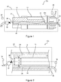
- the figure 2 schematically represents a portion of a torquemeter 200 according to a second embodiment of the invention.
- the torque meter comprises two shafts, a transmission shaft 12 and a reference shaft 14.
- the transmission shaft 12 and the reference shaft 14 are coaxial and unlike the first embodiment, it is the reference shaft 14 which is disposed inside the shaft. 12 of transmission.
- the parts of the torque meter 10 comprising the tone wheels are not shown because similar to the first embodiment.
- the torque meter 10 comprises a main temperature sensor 34 and an auxiliary temperature sensor 36 allowing a second measurement of the temperature at the outlet of the shaft.
- This auxiliary temperature sensor 36 makes it possible to refine the measurement and is useful in case of poor confinement of the transmission shaft 12 by the containment chamber 22, causing a variation in the temperature of the transmission shaft 12 due to an external element.
- an imperfect confinement of the transmission shaft 12 causes a temperature variation between the value at the input of the shaft, measured by the main temperature sensor 34, and the value at the output of the shaft, measured by the auxiliary temperature sensor 36, which remains low.
- the measured temperature value used for the correction of the measurement of the torque meter 10 may for example be the average between the temperatures measured at the input and at the output of the shaft, to take account of the small variation.
- the fluid used in the first and the second embodiment is, for example, oil.
- the turbomachine when using a torque meter according to one of these embodiments in an aircraft turbine engine, the turbomachine comprises a hydraulic oil circuit for supplying various equipment.
- the oil of this hydraulic circuit can be used to supply the fluid circulation circuit of the torque meter.
- elements of the hydraulic circuit can be reused, for example an oil temperature sensor distributed by the hydraulic circuit can be used as the main temperature sensor of the torque meter, if the oil does not undergo a temperature variation between this sensor and the input of the tree.
- the fluid used may for example be fuel (especially kerosene) or gas (especially air), which are also sometimes available in a turbomachine of an aircraft.
Landscapes
- Engineering & Computer Science (AREA)
- Physics & Mathematics (AREA)
- General Physics & Mathematics (AREA)
- Mechanical Engineering (AREA)
- General Engineering & Computer Science (AREA)
- Electromagnetism (AREA)
- Force Measurement Appropriate To Specific Purposes (AREA)
- Measuring Temperature Or Quantity Of Heat (AREA)
- Testing Of Devices, Machine Parts, Or Other Structures Thereof (AREA)
Priority Applications (1)
| Application Number | Priority Date | Filing Date | Title |
|---|---|---|---|
| PL17706274T PL3405652T3 (pl) | 2016-01-20 | 2017-01-17 | Czujnik momentu skręcającego |
Applications Claiming Priority (2)
| Application Number | Priority Date | Filing Date | Title |
|---|---|---|---|
| FR1650431A FR3046841B1 (fr) | 2016-01-20 | 2016-01-20 | Couplemetre a torsion |
| PCT/FR2017/050093 WO2017125671A1 (fr) | 2016-01-20 | 2017-01-17 | Couplemètre à torsion |
Publications (2)
| Publication Number | Publication Date |
|---|---|
| EP3405652A1 EP3405652A1 (fr) | 2018-11-28 |
| EP3405652B1 true EP3405652B1 (fr) | 2019-08-07 |
Family
ID=55451463
Family Applications (1)
| Application Number | Title | Priority Date | Filing Date |
|---|---|---|---|
| EP17706274.2A Active EP3405652B1 (fr) | 2016-01-20 | 2017-01-17 | Couplemètre à torsion |
Country Status (10)
| Country | Link |
|---|---|
| US (1) | US10677670B2 (pl) |
| EP (1) | EP3405652B1 (pl) |
| JP (1) | JP2019504317A (pl) |
| KR (1) | KR20180103872A (pl) |
| CN (1) | CN108431370B (pl) |
| CA (1) | CA3010592A1 (pl) |
| FR (1) | FR3046841B1 (pl) |
| PL (1) | PL3405652T3 (pl) |
| RU (1) | RU2722591C2 (pl) |
| WO (1) | WO2017125671A1 (pl) |
Families Citing this family (6)
| Publication number | Priority date | Publication date | Assignee | Title |
|---|---|---|---|---|
| CN110259431B (zh) * | 2019-06-05 | 2023-12-15 | 中国地质大学(武汉) | 一种基于摩擦纳米发电原理的涡轮钻具扭矩测量传感器 |
| FR3103273B1 (fr) * | 2019-11-14 | 2022-01-28 | Safran Aircraft Engines | Procédé de surveillance de la torsion d’un arbre rotatif sur une turbomachine d’un aéronef |
| CN113153439B (zh) * | 2021-05-06 | 2022-04-22 | 中国航发湖南动力机械研究所 | 一种具测扭功能的紧凑型涡轮轴结构 |
| IT202200006545A1 (it) * | 2022-04-01 | 2023-10-01 | Ge Avio Srl | Metodo ed apparecchiatura per calibrare un sensore di coppia di un motore aeronautico |
| CN115876386B (zh) * | 2022-11-25 | 2025-03-21 | 浙江凌昇动力科技有限公司 | 一种霍尔扭矩传感器的参数校正方法及设备、存储介质 |
| US11906017B1 (en) * | 2023-06-02 | 2024-02-20 | Pratt & Whitney Canada Corp. | Drive assembly and method of assembly |
Family Cites Families (14)
| Publication number | Priority date | Publication date | Assignee | Title |
|---|---|---|---|---|
| US4444063A (en) * | 1980-08-27 | 1984-04-24 | Sangamo Weston Limited | Torque measuring systems |
| GB2123568A (en) * | 1982-07-07 | 1984-02-01 | Rolls Royce | Measuring torque on gas- turbine engine shafts |
| SU1296865A1 (ru) * | 1985-03-06 | 1987-03-15 | Куйбышевский инженерно-строительный институт им.А.И.Микояна | Устройство дл измерени крут щего момента |
| FR2595821B1 (fr) * | 1986-03-12 | 1988-06-03 | Turbomeca | Procede et dispositif pour mesurer le couple transmis par un arbre soumis a des variations de temperature |
| US4899596A (en) * | 1988-05-04 | 1990-02-13 | Avco Corporation | Self-calibrating torque measuring system |
| JPH11252957A (ja) * | 1998-03-05 | 1999-09-17 | Nikon Corp | リニア型振動アクチュエータの特性測定装置 |
| JP2002120738A (ja) * | 2000-10-13 | 2002-04-23 | Koyo Seiko Co Ltd | 回転角度検出装置、トルク検出装置及び舵取装置 |
| US7533584B1 (en) * | 2007-11-12 | 2009-05-19 | Honeywell International Inc. | Systems and methods for temperature compensating torque sensors |
| FR2931552B1 (fr) * | 2008-05-21 | 2010-07-30 | Turbomeca | Dispositif de mesure de couple transmis par un arbre de puissance |
| DE102010052337A1 (de) * | 2010-11-25 | 2012-05-31 | Voith Patent Gmbh | Verfahren zur Einstellung des Arbeitsdruckes eines Getriebes |
| FR2972256B1 (fr) * | 2011-03-02 | 2013-03-29 | Turbomeca | Procede de calibration d'un couplemetre a torsion |
| DE102011075400A1 (de) * | 2011-05-06 | 2012-11-08 | Siemens Ag | Drehmomentsensoranordnung und Welle mit einer Drehmomentsensoranordnung |
| FR2993657B1 (fr) * | 2012-07-18 | 2015-05-01 | Ct Tech Des Ind Mecaniques | Dispositif de mesure d'un couple transmis par un arbre de transmission de puissance avec prise en compte des variations de temperature |
| JP6075269B2 (ja) * | 2013-11-05 | 2017-02-08 | 日本精工株式会社 | トルク測定装置付回転伝達装置 |
-
2016
- 2016-01-20 FR FR1650431A patent/FR3046841B1/fr active Active
-
2017
- 2017-01-17 CA CA3010592A patent/CA3010592A1/fr not_active Abandoned
- 2017-01-17 US US16/068,347 patent/US10677670B2/en active Active
- 2017-01-17 PL PL17706274T patent/PL3405652T3/pl unknown
- 2017-01-17 RU RU2018124456A patent/RU2722591C2/ru active
- 2017-01-17 JP JP2018535109A patent/JP2019504317A/ja not_active Ceased
- 2017-01-17 KR KR1020187019083A patent/KR20180103872A/ko not_active Withdrawn
- 2017-01-17 EP EP17706274.2A patent/EP3405652B1/fr active Active
- 2017-01-17 CN CN201780005787.2A patent/CN108431370B/zh active Active
- 2017-01-17 WO PCT/FR2017/050093 patent/WO2017125671A1/fr not_active Ceased
Non-Patent Citations (1)
| Title |
|---|
| None * |
Also Published As
| Publication number | Publication date |
|---|---|
| JP2019504317A (ja) | 2019-02-14 |
| US10677670B2 (en) | 2020-06-09 |
| FR3046841A1 (fr) | 2017-07-21 |
| PL3405652T3 (pl) | 2020-03-31 |
| FR3046841B1 (fr) | 2018-02-02 |
| RU2018124456A (ru) | 2020-02-21 |
| CN108431370B (zh) | 2020-11-17 |
| US20190025142A1 (en) | 2019-01-24 |
| RU2722591C2 (ru) | 2020-06-02 |
| RU2018124456A3 (pl) | 2020-04-10 |
| KR20180103872A (ko) | 2018-09-19 |
| WO2017125671A1 (fr) | 2017-07-27 |
| EP3405652A1 (fr) | 2018-11-28 |
| CN108431370A (zh) | 2018-08-21 |
| CA3010592A1 (fr) | 2017-07-27 |
Similar Documents
| Publication | Publication Date | Title |
|---|---|---|
| EP3405652B1 (fr) | Couplemètre à torsion | |
| US7532969B2 (en) | Gas turbine speed detection | |
| EP2265907A1 (fr) | Debitmetre instationnaire temps reel | |
| WO2009141261A1 (fr) | Dispositif de mesure de couple transmis par un arbre de puissance | |
| WO2023020797A1 (fr) | Capteur de détermination d'un niveau de liquide pour un réservoir d'aéronef, ensemble d'un réservoir et d'un capteur, procédé d'utilisation d'un tel capteur | |
| FR2595821A1 (fr) | Procede et dispositif pour mesurer le couple transmis par un arbre soumis a des variations de temperature | |
| FR3025885A1 (fr) | Dispositif de mesure de grandeurs aerodynamiques destine a etre place dans une veine d'ecoulement d'une turbomachine | |
| WO2014207369A1 (fr) | Ecrou de palier pour la mesure de regime de rotation d'un arbre lie a une turbomachine et dispositif de mesure associe | |
| CA2823172A1 (fr) | Dispositif et procede de surveillance de rotor | |
| WO2016027024A1 (fr) | Reducteur de vitesse pour une turbomachine | |
| CA2364922C (fr) | Dispositif de freinage a courants de foucault | |
| FR3059095A1 (fr) | Debitmetre thermique massique | |
| EP2681525B1 (fr) | Procede de calibration d'un couplemetre a torsion | |
| FR3068390A1 (fr) | Dispositif pour l'assemblage d'une turbomachine, et procede utilisant le dispositif | |
| FR2860067A1 (fr) | Dispositif pour mesurer la rugosite hydraulique de la surface interne d'un pipe-line | |
| WO2021234239A1 (fr) | Dispositif hydraulique de mesure de couple pour groupe moteur d'aéronef | |
| WO2024121289A1 (fr) | Procédé et système de contrôle de la perméabilité d'un circuit de lubrification d'une turbomachine d'aéronef | |
| FR3125845A1 (fr) | Procédé de détermination du fluage d’aubes | |
| EP3364011B1 (fr) | Moteur a pistons muni d'un systeme de mesure de couple, vehicule muni de ce moteur, et procede utilise par ce moteur | |
| EP4607185A1 (fr) | Systeme de determination d'une quantite d'emissions de dioxyde de carbone resultant de l'echauffement d'un conducteur electrique d'un cable electrique par effet joule | |
| FR3112364A1 (fr) | Témoin d’usure pour une turbomachine, turbomachine équipée d’un tel témoin d’usure, et procédé de mesure d’un jeu entre la périphérie externe d’une roue aubagée et un revêtement abradable dans une telle turbomachine | |
| FR2860868A1 (fr) | Dispositif pour controler la derive d'un organe de mesure du debit et/ou du volume d'un fluide et/ou calibrer ledit organe de mesure | |
| FR2771505A1 (fr) | Sonde thermique pour mesurer la temperature d'un ecoulement de fluide | |
| FR3150292A1 (fr) | Machine d’essai | |
| FR3087259A1 (fr) | Dispositif d'alimentation en air comprime d'un aeronef et son procede d'utilisation |
Legal Events
| Date | Code | Title | Description |
|---|---|---|---|
| STAA | Information on the status of an ep patent application or granted ep patent |
Free format text: STATUS: UNKNOWN |
|
| STAA | Information on the status of an ep patent application or granted ep patent |
Free format text: STATUS: THE INTERNATIONAL PUBLICATION HAS BEEN MADE |
|
| PUAI | Public reference made under article 153(3) epc to a published international application that has entered the european phase |
Free format text: ORIGINAL CODE: 0009012 |
|
| STAA | Information on the status of an ep patent application or granted ep patent |
Free format text: STATUS: REQUEST FOR EXAMINATION WAS MADE |
|
| 17P | Request for examination filed |
Effective date: 20180629 |
|
| AK | Designated contracting states |
Kind code of ref document: A1 Designated state(s): AL AT BE BG CH CY CZ DE DK EE ES FI FR GB GR HR HU IE IS IT LI LT LU LV MC MK MT NL NO PL PT RO RS SE SI SK SM TR |
|
| AX | Request for extension of the european patent |
Extension state: BA ME |
|
| DAV | Request for validation of the european patent (deleted) | ||
| DAX | Request for extension of the european patent (deleted) | ||
| GRAP | Despatch of communication of intention to grant a patent |
Free format text: ORIGINAL CODE: EPIDOSNIGR1 |
|
| STAA | Information on the status of an ep patent application or granted ep patent |
Free format text: STATUS: GRANT OF PATENT IS INTENDED |
|
| INTG | Intention to grant announced |
Effective date: 20190510 |
|
| GRAS | Grant fee paid |
Free format text: ORIGINAL CODE: EPIDOSNIGR3 |
|
| GRAA | (expected) grant |
Free format text: ORIGINAL CODE: 0009210 |
|
| STAA | Information on the status of an ep patent application or granted ep patent |
Free format text: STATUS: THE PATENT HAS BEEN GRANTED |
|
| AK | Designated contracting states |
Kind code of ref document: B1 Designated state(s): AL AT BE BG CH CY CZ DE DK EE ES FI FR GB GR HR HU IE IS IT LI LT LU LV MC MK MT NL NO PL PT RO RS SE SI SK SM TR |
|
| REG | Reference to a national code |
Ref country code: GB Ref legal event code: FG4D Free format text: NOT ENGLISH |
|
| REG | Reference to a national code |
Ref country code: CH Ref legal event code: EP Ref country code: AT Ref legal event code: REF Ref document number: 1164174 Country of ref document: AT Kind code of ref document: T Effective date: 20190815 |
|
| REG | Reference to a national code |
Ref country code: DE Ref legal event code: R096 Ref document number: 602017005969 Country of ref document: DE |
|
| REG | Reference to a national code |
Ref country code: IE Ref legal event code: FG4D Free format text: LANGUAGE OF EP DOCUMENT: FRENCH |
|
| REG | Reference to a national code |
Ref country code: NL Ref legal event code: MP Effective date: 20190807 |
|
| REG | Reference to a national code |
Ref country code: LT Ref legal event code: MG4D |
|
| PG25 | Lapsed in a contracting state [announced via postgrant information from national office to epo] |
Ref country code: HR Free format text: LAPSE BECAUSE OF FAILURE TO SUBMIT A TRANSLATION OF THE DESCRIPTION OR TO PAY THE FEE WITHIN THE PRESCRIBED TIME-LIMIT Effective date: 20190807 Ref country code: LT Free format text: LAPSE BECAUSE OF FAILURE TO SUBMIT A TRANSLATION OF THE DESCRIPTION OR TO PAY THE FEE WITHIN THE PRESCRIBED TIME-LIMIT Effective date: 20190807 Ref country code: SE Free format text: LAPSE BECAUSE OF FAILURE TO SUBMIT A TRANSLATION OF THE DESCRIPTION OR TO PAY THE FEE WITHIN THE PRESCRIBED TIME-LIMIT Effective date: 20190807 Ref country code: NL Free format text: LAPSE BECAUSE OF FAILURE TO SUBMIT A TRANSLATION OF THE DESCRIPTION OR TO PAY THE FEE WITHIN THE PRESCRIBED TIME-LIMIT Effective date: 20190807 Ref country code: BG Free format text: LAPSE BECAUSE OF FAILURE TO SUBMIT A TRANSLATION OF THE DESCRIPTION OR TO PAY THE FEE WITHIN THE PRESCRIBED TIME-LIMIT Effective date: 20191107 Ref country code: FI Free format text: LAPSE BECAUSE OF FAILURE TO SUBMIT A TRANSLATION OF THE DESCRIPTION OR TO PAY THE FEE WITHIN THE PRESCRIBED TIME-LIMIT Effective date: 20190807 Ref country code: NO Free format text: LAPSE BECAUSE OF FAILURE TO SUBMIT A TRANSLATION OF THE DESCRIPTION OR TO PAY THE FEE WITHIN THE PRESCRIBED TIME-LIMIT Effective date: 20191107 Ref country code: PT Free format text: LAPSE BECAUSE OF FAILURE TO SUBMIT A TRANSLATION OF THE DESCRIPTION OR TO PAY THE FEE WITHIN THE PRESCRIBED TIME-LIMIT Effective date: 20191209 |
|
| REG | Reference to a national code |
Ref country code: AT Ref legal event code: MK05 Ref document number: 1164174 Country of ref document: AT Kind code of ref document: T Effective date: 20190807 |
|
| PG25 | Lapsed in a contracting state [announced via postgrant information from national office to epo] |
Ref country code: IS Free format text: LAPSE BECAUSE OF FAILURE TO SUBMIT A TRANSLATION OF THE DESCRIPTION OR TO PAY THE FEE WITHIN THE PRESCRIBED TIME-LIMIT Effective date: 20191207 Ref country code: RS Free format text: LAPSE BECAUSE OF FAILURE TO SUBMIT A TRANSLATION OF THE DESCRIPTION OR TO PAY THE FEE WITHIN THE PRESCRIBED TIME-LIMIT Effective date: 20190807 Ref country code: AL Free format text: LAPSE BECAUSE OF FAILURE TO SUBMIT A TRANSLATION OF THE DESCRIPTION OR TO PAY THE FEE WITHIN THE PRESCRIBED TIME-LIMIT Effective date: 20190807 Ref country code: GR Free format text: LAPSE BECAUSE OF FAILURE TO SUBMIT A TRANSLATION OF THE DESCRIPTION OR TO PAY THE FEE WITHIN THE PRESCRIBED TIME-LIMIT Effective date: 20191108 Ref country code: LV Free format text: LAPSE BECAUSE OF FAILURE TO SUBMIT A TRANSLATION OF THE DESCRIPTION OR TO PAY THE FEE WITHIN THE PRESCRIBED TIME-LIMIT Effective date: 20190807 Ref country code: ES Free format text: LAPSE BECAUSE OF FAILURE TO SUBMIT A TRANSLATION OF THE DESCRIPTION OR TO PAY THE FEE WITHIN THE PRESCRIBED TIME-LIMIT Effective date: 20190807 |
|
| PG25 | Lapsed in a contracting state [announced via postgrant information from national office to epo] |
Ref country code: TR Free format text: LAPSE BECAUSE OF FAILURE TO SUBMIT A TRANSLATION OF THE DESCRIPTION OR TO PAY THE FEE WITHIN THE PRESCRIBED TIME-LIMIT Effective date: 20190807 |
|
| PG25 | Lapsed in a contracting state [announced via postgrant information from national office to epo] |
Ref country code: AT Free format text: LAPSE BECAUSE OF FAILURE TO SUBMIT A TRANSLATION OF THE DESCRIPTION OR TO PAY THE FEE WITHIN THE PRESCRIBED TIME-LIMIT Effective date: 20190807 Ref country code: DK Free format text: LAPSE BECAUSE OF FAILURE TO SUBMIT A TRANSLATION OF THE DESCRIPTION OR TO PAY THE FEE WITHIN THE PRESCRIBED TIME-LIMIT Effective date: 20190807 Ref country code: RO Free format text: LAPSE BECAUSE OF FAILURE TO SUBMIT A TRANSLATION OF THE DESCRIPTION OR TO PAY THE FEE WITHIN THE PRESCRIBED TIME-LIMIT Effective date: 20190807 Ref country code: EE Free format text: LAPSE BECAUSE OF FAILURE TO SUBMIT A TRANSLATION OF THE DESCRIPTION OR TO PAY THE FEE WITHIN THE PRESCRIBED TIME-LIMIT Effective date: 20190807 |
|
| PG25 | Lapsed in a contracting state [announced via postgrant information from national office to epo] |
Ref country code: IS Free format text: LAPSE BECAUSE OF FAILURE TO SUBMIT A TRANSLATION OF THE DESCRIPTION OR TO PAY THE FEE WITHIN THE PRESCRIBED TIME-LIMIT Effective date: 20200224 Ref country code: SM Free format text: LAPSE BECAUSE OF FAILURE TO SUBMIT A TRANSLATION OF THE DESCRIPTION OR TO PAY THE FEE WITHIN THE PRESCRIBED TIME-LIMIT Effective date: 20190807 Ref country code: SK Free format text: LAPSE BECAUSE OF FAILURE TO SUBMIT A TRANSLATION OF THE DESCRIPTION OR TO PAY THE FEE WITHIN THE PRESCRIBED TIME-LIMIT Effective date: 20190807 |
|
| REG | Reference to a national code |
Ref country code: DE Ref legal event code: R097 Ref document number: 602017005969 Country of ref document: DE |
|
| PLBE | No opposition filed within time limit |
Free format text: ORIGINAL CODE: 0009261 |
|
| STAA | Information on the status of an ep patent application or granted ep patent |
Free format text: STATUS: NO OPPOSITION FILED WITHIN TIME LIMIT |
|
| PG2D | Information on lapse in contracting state deleted |
Ref country code: IS |
|
| 26N | No opposition filed |
Effective date: 20200603 |
|
| PG25 | Lapsed in a contracting state [announced via postgrant information from national office to epo] |
Ref country code: MC Free format text: LAPSE BECAUSE OF FAILURE TO SUBMIT A TRANSLATION OF THE DESCRIPTION OR TO PAY THE FEE WITHIN THE PRESCRIBED TIME-LIMIT Effective date: 20190807 |
|
| REG | Reference to a national code |
Ref country code: CH Ref legal event code: PL |
|
| REG | Reference to a national code |
Ref country code: BE Ref legal event code: MM Effective date: 20200131 |
|
| PG25 | Lapsed in a contracting state [announced via postgrant information from national office to epo] |
Ref country code: LU Free format text: LAPSE BECAUSE OF NON-PAYMENT OF DUE FEES Effective date: 20200117 |
|
| PG25 | Lapsed in a contracting state [announced via postgrant information from national office to epo] |
Ref country code: BE Free format text: LAPSE BECAUSE OF NON-PAYMENT OF DUE FEES Effective date: 20200131 Ref country code: CH Free format text: LAPSE BECAUSE OF NON-PAYMENT OF DUE FEES Effective date: 20200131 Ref country code: LI Free format text: LAPSE BECAUSE OF NON-PAYMENT OF DUE FEES Effective date: 20200131 |
|
| PG25 | Lapsed in a contracting state [announced via postgrant information from national office to epo] |
Ref country code: IE Free format text: LAPSE BECAUSE OF NON-PAYMENT OF DUE FEES Effective date: 20200117 |
|
| PG25 | Lapsed in a contracting state [announced via postgrant information from national office to epo] |
Ref country code: MT Free format text: LAPSE BECAUSE OF FAILURE TO SUBMIT A TRANSLATION OF THE DESCRIPTION OR TO PAY THE FEE WITHIN THE PRESCRIBED TIME-LIMIT Effective date: 20190807 Ref country code: CY Free format text: LAPSE BECAUSE OF FAILURE TO SUBMIT A TRANSLATION OF THE DESCRIPTION OR TO PAY THE FEE WITHIN THE PRESCRIBED TIME-LIMIT Effective date: 20190807 |
|
| PG25 | Lapsed in a contracting state [announced via postgrant information from national office to epo] |
Ref country code: MK Free format text: LAPSE BECAUSE OF FAILURE TO SUBMIT A TRANSLATION OF THE DESCRIPTION OR TO PAY THE FEE WITHIN THE PRESCRIBED TIME-LIMIT Effective date: 20190807 |
|
| PG25 | Lapsed in a contracting state [announced via postgrant information from national office to epo] |
Ref country code: SI Free format text: LAPSE BECAUSE OF FAILURE TO SUBMIT A TRANSLATION OF THE DESCRIPTION OR TO PAY THE FEE WITHIN THE PRESCRIBED TIME-LIMIT Effective date: 20190807 |
|
| PGFP | Annual fee paid to national office [announced via postgrant information from national office to epo] |
Ref country code: PL Payment date: 20241223 Year of fee payment: 9 |
|
| PGFP | Annual fee paid to national office [announced via postgrant information from national office to epo] |
Ref country code: GB Payment date: 20241219 Year of fee payment: 9 |
|
| PGFP | Annual fee paid to national office [announced via postgrant information from national office to epo] |
Ref country code: FR Payment date: 20241219 Year of fee payment: 9 |
|
| PGFP | Annual fee paid to national office [announced via postgrant information from national office to epo] |
Ref country code: CZ Payment date: 20241219 Year of fee payment: 9 |
|
| PGFP | Annual fee paid to national office [announced via postgrant information from national office to epo] |
Ref country code: DE Payment date: 20241218 Year of fee payment: 9 |
|
| PGFP | Annual fee paid to national office [announced via postgrant information from national office to epo] |
Ref country code: IT Payment date: 20250107 Year of fee payment: 9 |