EP3405355B1 - System zum befüllen und entlüften eines reifens - Google Patents
System zum befüllen und entlüften eines reifens Download PDFInfo
- Publication number
- EP3405355B1 EP3405355B1 EP17702683.8A EP17702683A EP3405355B1 EP 3405355 B1 EP3405355 B1 EP 3405355B1 EP 17702683 A EP17702683 A EP 17702683A EP 3405355 B1 EP3405355 B1 EP 3405355B1
- Authority
- EP
- European Patent Office
- Prior art keywords
- valve
- chamber
- inflation
- communication
- deflation
- Prior art date
- Legal status (The legal status is an assumption and is not a legal conclusion. Google has not performed a legal analysis and makes no representation as to the accuracy of the status listed.)
- Active
Links
Images


Classifications
-
- B—PERFORMING OPERATIONS; TRANSPORTING
- B60—VEHICLES IN GENERAL
- B60C—VEHICLE TYRES; TYRE INFLATION; TYRE CHANGING; CONNECTING VALVES TO INFLATABLE ELASTIC BODIES IN GENERAL; DEVICES OR ARRANGEMENTS RELATED TO TYRES
- B60C23/00—Devices for measuring, signalling, controlling, or distributing tyre pressure or temperature, specially adapted for mounting on vehicles; Arrangement of tyre inflating devices on vehicles, e.g. of pumps or of tanks; Tyre cooling arrangements
- B60C23/001—Devices for manually or automatically controlling or distributing tyre pressure whilst the vehicle is moving
- B60C23/004—Devices for manually or automatically controlling or distributing tyre pressure whilst the vehicle is moving the control being done on the wheel, e.g. using a wheel-mounted reservoir
-
- F—MECHANICAL ENGINEERING; LIGHTING; HEATING; WEAPONS; BLASTING
- F16—ENGINEERING ELEMENTS AND UNITS; GENERAL MEASURES FOR PRODUCING AND MAINTAINING EFFECTIVE FUNCTIONING OF MACHINES OR INSTALLATIONS; THERMAL INSULATION IN GENERAL
- F16K—VALVES; TAPS; COCKS; ACTUATING-FLOATS; DEVICES FOR VENTING OR AERATING
- F16K11/00—Multiple-way valves, e.g. mixing valves; Pipe fittings incorporating such valves
- F16K11/02—Multiple-way valves, e.g. mixing valves; Pipe fittings incorporating such valves with all movable sealing faces moving as one unit
- F16K11/04—Multiple-way valves, e.g. mixing valves; Pipe fittings incorporating such valves with all movable sealing faces moving as one unit comprising only lift valves
- F16K11/048—Multiple-way valves, e.g. mixing valves; Pipe fittings incorporating such valves with all movable sealing faces moving as one unit comprising only lift valves with valve seats positioned between movable valve members
-
- F—MECHANICAL ENGINEERING; LIGHTING; HEATING; WEAPONS; BLASTING
- F16—ENGINEERING ELEMENTS AND UNITS; GENERAL MEASURES FOR PRODUCING AND MAINTAINING EFFECTIVE FUNCTIONING OF MACHINES OR INSTALLATIONS; THERMAL INSULATION IN GENERAL
- F16K—VALVES; TAPS; COCKS; ACTUATING-FLOATS; DEVICES FOR VENTING OR AERATING
- F16K11/00—Multiple-way valves, e.g. mixing valves; Pipe fittings incorporating such valves
- F16K11/10—Multiple-way valves, e.g. mixing valves; Pipe fittings incorporating such valves with two or more closure members not moving as a unit
- F16K11/14—Multiple-way valves, e.g. mixing valves; Pipe fittings incorporating such valves with two or more closure members not moving as a unit operated by one actuating member, e.g. a handle
- F16K11/18—Multiple-way valves, e.g. mixing valves; Pipe fittings incorporating such valves with two or more closure members not moving as a unit operated by one actuating member, e.g. a handle with separate operating movements for separate closure members
-
- F—MECHANICAL ENGINEERING; LIGHTING; HEATING; WEAPONS; BLASTING
- F16—ENGINEERING ELEMENTS AND UNITS; GENERAL MEASURES FOR PRODUCING AND MAINTAINING EFFECTIVE FUNCTIONING OF MACHINES OR INSTALLATIONS; THERMAL INSULATION IN GENERAL
- F16K—VALVES; TAPS; COCKS; ACTUATING-FLOATS; DEVICES FOR VENTING OR AERATING
- F16K31/00—Actuating devices; Operating means; Releasing devices
- F16K31/12—Actuating devices; Operating means; Releasing devices actuated by fluid
- F16K31/122—Actuating devices; Operating means; Releasing devices actuated by fluid the fluid acting on a piston
-
- F—MECHANICAL ENGINEERING; LIGHTING; HEATING; WEAPONS; BLASTING
- F16—ENGINEERING ELEMENTS AND UNITS; GENERAL MEASURES FOR PRODUCING AND MAINTAINING EFFECTIVE FUNCTIONING OF MACHINES OR INSTALLATIONS; THERMAL INSULATION IN GENERAL
- F16K—VALVES; TAPS; COCKS; ACTUATING-FLOATS; DEVICES FOR VENTING OR AERATING
- F16K31/00—Actuating devices; Operating means; Releasing devices
- F16K31/12—Actuating devices; Operating means; Releasing devices actuated by fluid
- F16K31/122—Actuating devices; Operating means; Releasing devices actuated by fluid the fluid acting on a piston
- F16K31/1225—Actuating devices; Operating means; Releasing devices actuated by fluid the fluid acting on a piston with a plurality of pistons
Definitions
- the invention relates to the technical sector of inflation-deflation systems of a tire, in particular controlled remotely from the passenger compartment of a vehicle for example.
- Said inflation-deflation systems make it possible to adjust the pressure of the tires from inside the vehicle by simply interacting with a control interface. This is very useful for rally, military, agricultural or civil type vehicles. These systems are generally designed for all vehicle pilots who need to vary the tire pressure, and in particular to vary the tire pressure to suit the coatings on which they travel, the loads they carry, and the speed of movement of the vehicle.
- the devices described in these patent applications include arrangements for injecting air at low or high pressure from a compressor connected to an air inlet to move a set of valves and inflate the tire. Conversely, when air is injected at high or low pressure, a set of valves is moved and the tire is brought into communication with the outside air and is deflated.
- this requires the arrangement of a compressor and an air passage hose associated with a rotary joint between the compressor and the inflation-deflation device mounted on the tire.
- the presence of the rotating joint causes risks of leaks.
- the arrangement of the rotary joint is complex and must especially be in the presence of a lubricant.
- the problem to be solved by the invention is therefore to provide an inflation-deflation system of a tire that comprises a wheel to overcome the arrangement of a rotary joint.
- Another object of the invention is to provide such a system which is of simple design and which is autonomous.
- the system according to the invention makes it possible to inflate-deflate a tire by means of a valve which is subject to an air reserve on the wheel and allows to overcome the implementation of a rotating joint.
- the system is simpler and the risks of leakage are reduced.
- the system according to the invention makes it possible to control the inflation by means of an inflation solenoid valve, and to control the deflation by means of a deflation solenoid valve.
- These solenoid valves allow, by injecting a small volume of air, to put the tire in communication with the reserve for inflating said tire, or with the outside of the valve for deflation.
- the air flow used to control inflation-deflation is distinct from the air flow injected into the tire for inflation as such.
- the solenoid valves are controlled via a wireless transceiver system.
- the solenoid valves can be radio controlled or controlled by various wireless communication standards well known in the state of the art, for example "LTE » « NFC »« Bluetooth » « Wi-Fi » etc. which should be considered as transceiver systems according to the interpretation of the present invention.
- said system comprises a pressure sensor subject to the transmitter system. -receiver, in communication with the master bedroom.
- the invention relates to a system (1) for inflating and deflating a tire (2) comprising a wheel, from an air reserve (3) confined at a pressure greater than that of the tire (2). .
- the air reserve (3) is embedded on the wheel of the tire (2) and may in particular be arranged inside said tire (2).
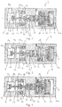
- the system (1) comprises a valve (4), also embedded on the wheel, in the form of a hollow body (4a) comprising a main chamber (5) in communication with the tire (2) via an inlet (2a), and a secondary chamber (6) in communication with the reserve (3) via an inlet (3a).
- the valve (4) includes an inflation port (7) secured to an inflation solenoid valve (8) and a deflation port (9) secured to a deflation solenoid valve (10).
- the solenoid valves (8, 10) are radio-controlled via a transceiver system (11, 12) for remotely controlling the inflation-deflation, in particular from a control panel arranged for example in the case of the passenger compartment of the vehicle on which the system (1) is installed.
- the main chamber (5) is arranged at a first end of the hollow body (4a).
- the valve (4) then comprises an exhaust chamber (13).
- the main chamber (5) and the exhaust chamber (13) communicate with each other via an orifice closed by a first valve (14) arranged at the interior of said main chamber (5).
- the first valve (14) is displaceably mounted inside the main chamber (5) between a rest position in which it closes the communication with the exhaust chamber (13) and an open position, at the against an elastic return member (15) mounted inside the main chamber (5).
- the exhaust chamber (13) comprises at least one vent orifice (16) closed by an exhaust valve (17) movable in an open position against an elastic return member (15a) arranged in the exhaust chamber (13).
- the exhaust chamber (13) is arranged between the main chamber (5) and the secondary chamber (6), and is considered as an intermediate chamber.
- the secondary chamber (6) is then arranged in the valve (4) in communication via an orifice with the exhaust chamber (13).
- the orifice is closed by a second valve (18) arranged inside the exhaust chamber (13) and movable between a rest position in which it closes the orifice, an open position, and a position exhaust system in which it pushes the exhaust valve (17) in the open position and venting.
- the secondary chamber (6) is connected to the air supply (3) for inflating the tire (2).
- the secondary chamber (6) comprises a third valve (19) arranged inside the secondary chamber (6) to close the communication with the exhaust chamber (13).
- the first, second and third valves (14, 18, 19) are connected to each other and secured to first and second pistons (20, 21) arranged in a common chamber (22).
- the inflation port (7) opens into the common chamber (22) between the first and second pistons (20, 21), and the deflation orifice (9) opens into the common chamber (22). ) behind the second piston (21), namely opposite the first piston (20).
- the air injected by the inflation solenoid valve (8) through the inflation orifice (7) causes the displacement of the first piston (20) and causes the opening first and second valves (14, 18), against the elastic return member (15).
- the air present in the reserve (3) escapes and passes successively in the secondary chamber (6), in the exhaust chamber (13), in the main chamber (5), and is injected into the tire (2) for inflation as such.
- the common chamber (22) is no longer under pressure.
- the first piston (20) is pushed back to its original position and the first and second valves (14, 18) are closed which corresponds to the rest position of the valve (4).
- the air injected by the deflation solenoid valve (10) through the deflation orifice (9) causes the displacement of the second piston (21) which further displaces the first piston (20) in a deflation position.
- the third valve (19) is moved into a position in which it closes the communication between the secondary chamber (6) connected to the reserve (3), and the exhaust chamber (13).
- the second valve (18) is moved into the exhaust position in which it forces the opening of the exhaust valve (17) of the exhaust chamber (13) against the elastic return member ( 15a).
- the first valve (14) is also moved to the open position to communicate the main chamber (5) with the exhaust chamber (13) whose vent port (16) is open. In this way, the air in the tire (2) is discharged from the valve (4) and the tire (2) is deflated.
- valve (4) of the device according to the invention illustrated in FIGS. Figures 5 to 7 the secondary (6) and exhaust (13) chambers are arranged on either side of the main chamber (5).
- the valve (4) comprises at one end an inflation chamber (23) receiving a first piston (20) and into which the inflation opening (7) opens, and at the other end a deflation chamber (24). receiving a second piston (21) and into which opens the deflation orifice (9).
- the main chamber (5) in connection with the tire (2) communicates, on both sides via orifices, with the secondary chamber (6) connected to the reserve (3) and with the chamber of exhaust (13) comprising at least one venting port (16).
- First and second valves (14, 18) are arranged inside the main chamber (5) and are adapted to adopt closing positions of the orifices to close the communication between the main chamber (5) and the secondary chambers (6) and exhaust (13), and opening positions, against an elastic return member (15) arranged between the first and second valves (14, 18).
- the second valve (18) which is arranged to close the communication with the secondary chamber (6) is secured to the first piston (20) so that the air injected by the inflation solenoid valve (8) through the orifice inflating (7) in the inflation chamber (23) causes the displacement of the first piston (20) and the opening of the second valve (18) and allows inflation of the tire (2).
- the inflation chamber (23) is no longer under pressure.
- the pressure of the air supply (3) on the first piston (20) the pressure of the tire (2) and the elastic return member (15)
- the second valve (18) is closed and the first piston (20) is pushed back to its original position corresponding to the rest position of the valve (4).
- the first valve (14) which is arranged to close the communication with the exhaust chamber (13) is secured to the second piston (21) so that the air injected by the deflation solenoid valve (10) into the chamber deflation (24) causes the displacement of the second piston (21) and the opening of the first valve (14) and allows deflation of the tire (2).
- the deflation chamber (24) When the air is no longer injected through the deflation orifice (9), the deflation chamber (24) is no longer under pressure. Under the effect of the elastic return member (15) and the pressure of the tire (2), the first valve (14) is closed and the second piston (21) is pushed back to its original position corresponding to the rest position of the valve (4).
- a pressure sensor (25) is connected to the main chamber (5) through an input (26) and is connected to the transceiver system (11, 12).
- the pressure sensor (25) allows in the rest position of the valve (4) to measure the pressure inside the tire (2).
- the skilled person will adapt the nature of the pressure sensor to implement according to the embodiment of the invention.
- the sensor makes it possible to evaluate the pressure of the reserve (3) and the tire (2) by knowing the pressure of the tire (2) before inflation and taking into account the pressure losses upstream and downstream of the tire. sensor.
- the pressure measured by the sensor also makes it possible to estimate the inflation-deflation time given the known pressure losses of the valve (4). Since the sensor is connected to the transceiver system (11, 12), these measurements can be displayed in the passenger compartment of the vehicle.
- the system (1) allows inflation-deflation of a tire (2) by means of a valve (4) which is subject to an air reserve (3) embedded on the wheel and allows to overcome the implementation of a rotating joint and also an electrical connection between the wheel and the chassis of the vehicle.
- the system (1) is simpler and the risks of leakage are reduced.
- the system (1) makes it possible to control the inflation by means of an inflation solenoid valve (8) and the deflation by means of a deflation solenoid valve (10).
- These solenoid valves (8, 10) make it possible, by injecting a certain air pressure, to put the tire (2) in communication with the reserve (3) for inflating said tire (2) or with the outside of the valve ( 4) for deflation.
- the airflow used to control inflation-deflation is distinct from the flow of air injected into the tire (2) for inflation as such.
- the valve comprises an inflation control inlet (7), a deflation control inlet (9), an intake inlet (3a) and an inflation inlet (2a).
- the system (1) according to the invention is autonomous and remotely controllable.
- the piloting of the valve (4) for inflating-deflating, performed by the solenoid valves (8, 10), is achieved by injecting small volumes of air under pressure, which allows the use of small solenoid valves of low power and low power consumption.
- the supply of said solenoid valves (8, 10) can be by electric batteries or rechargeable batteries
Landscapes
- Engineering & Computer Science (AREA)
- General Engineering & Computer Science (AREA)
- Mechanical Engineering (AREA)
- Check Valves (AREA)
- Vehicle Cleaning, Maintenance, Repair, Refitting, And Outriggers (AREA)
- Tires In General (AREA)
Claims (6)
- System (1) zum Aufpumpen- Entleeren eines Reifens (2), der zu einem Rad gehört, dieses System enthält eine Luftreserve (3) und ein Ventil (4), enthalten im Rad, die Luft ist in der Luftreserve (3) eingeschlossen, mit einem höheren Druck als der des Reifens (2), das Ventil (4) steht einerseits in Verbindung mit der Luftreserve (3) und andererseits mit dem Reifen (2), dadurch gekennzeichnet, dass das genannte Ventil (4) Steuervorrichtungen enthält, die einnehmen können:- eine Ruheposition, in der diese Steuervorrichtungen eine stabile und hermetische Verbindung zwischen dem Reifen (2) und dem Ventil (4) sicherstellen;- eine Aufpumpposition, in der diese Steuervorrichtungen eine Verbindung zwischen dem Reifen (2) und der Luftreserve (3) sicherstellen, indem sie durch Luft, die in das Ventil (4) über ein Aufpump- Magnetventil (8) eingeblasen wird, das mit der Luftreserve (3) verbunden ist, verstellt werden;- eine Entleerposition, in der diese Steuervorrichtungen eine Verbindung zwischen dem Reifen (2) und der Außenseite des Ventils sicherstellen, indem sie durch Luft, die in das Ventil (4) über ein Entleer- Magnetventil (10) eingeblasen wird, das mit der Luftreserve (3) verbunden ist, verstellt werden.
- System (1) nach Anspruch 1 dadurch gekennzeichnet, dass die Magnetventile (8, 10) über ein drahtloses Sender- Empfänger- System (11, 12) gesteuert werden.
- System (1) nach einem der vorstehenden Ansprüche 1 und 2, dadurch gekennzeichnet, dass das Ventil (4) einen Hohlkörper (4a) enthält, der besteht:- aus einer Hauptkammer (5), die in Verbindung mit dem Reifen (2) steht;- einer Auslasskammer (13), die mindestens eine Auslassöffnung (16) enthält und mit der Hauptkammer (5) in Verbindung steht;- einer Sekundärkammer (6), die in Verbindung mit der Luftreserve (3) steht;- einer ersten Klappe (14), angeordnet im Inneren der Hauptkammer (5) zum Verschließen der Verbindung mit der Auslasskammer (13);- eine zweite Klappe (18), angeordnet zum direkten oder indirekten Verschließen der Verbindung zwischen der Hauptkammer (5) und der Sekundärkammer (6);- eine Aufpumpöffnung (7), verbunden mit dem Aufpump- Magnetventil (8);- eine Entleeröffnung (9), verbunden mit dem Entleer- Magnetventil (10).
- System (1) nach Anspruch 3, dadurch gekennzeichnet, dass:- die Entlüftungsöffnung (16) der Auslasskammer (13) durch eine Auslassklappe (17) verschlossen werden kann, die in eine Öffnungsposition gegen eine elastische Rückstellvorrichtung (15a) verstellt werden kann;- die zweite Klappe (18) im Inneren der Auslasskammer (13) angeordnet ist, die die Form einer Zwischenkammer hat, die ebenfalls mit der Sekundärkammer (6) in Verbindung steht;- das Ventil (4) eine dritte Klappe (19) beinhaltet, angeordnet im Inneren der Sekundärkammer (6), zum Verschließen der Verbindung mit der Auslasskammer (13);- die erste, zweite und dritte Klappe (14, 18, 19) miteinander verbunden sind und von einem ersten und einem zweiten Kolben (20, 21) abhängen, die in einer gemeinsamen Kammer (22) untergebracht sind;- die Aufpumpöffnung (7) in der gemeinsamen Kammer (22) zwischen dem ersten und zweiten Kolben (20, 21) mündet und die Entleeröffnung (9) zwischen dem zweiten Kolben (21) und der gemeinsamen Kammer (22) mündet, so dass:- die vom Aufpump- Magnetventil (8) eingeblasene Luft zur Verschiebung des ersten Kolbens (20) führt und so das Öffnen der ersten und zweiten Klappe (14. 18) gegen eine elastische Rückstellvorrichtung (15) verursacht und damit das Aufpumpen des Reifens (2) erlaubt;- die vom Entleer- Magnetventil (8) eingeblasene Luft zur Verschiebung des zweiten Kolbens (21) führt, der den ersten Kolben (20) noch weiter verschiebt und so das Schließen der dritten Klappe (19) und das Öffnen der Auslassklappe (17) verursacht, die von der zweiten Klappe (18) geschoben wird und damit das Entleeren des Reifens (2) ermöglicht.
- System (1) nach Anspruch 3, dadurch gekennzeichnet, dass- die zweite Klappe (18) im Inneren der Hauptkammer (5) angeordnet ist und in direkter Verbindung mit der Sekundärkammer (6) steht und von einem ersten Kolben (20) abhängt, untergebracht in einer Aufpumpkammer (23), in der die Aufpumpöffnung (7) mündet, so dass die vom Aufpump- Magnetventil (8) eingeblasene Luft zur Verschiebung des ersten Kolbens (20) und der Öffnung der zweiten Klappe (18) führt und so das Aufpumpen des Reifens (2) erlaubt;- die erste Klappe (14) von einem zweiten Kolben (21) abhängt, der in einer Entleerkammer (24) untergebracht ist, in der die Entleeröffnung (9) mündet, so dass die vom Entleer- Magnetventil (10) eingeblasene Luft zur Verschiebung des zweiten Kolbens (21) und der Öffnung der ersten Klappe (14) führt und so das Entleeren des Reifens (2) erlaubt;- das Ventil (4) eine elastische Rückstellvorrichtung (15) umfasst, angeordnet zwischen der ersten und der zweiten Klappe (14, 18), um diese in der Ruhe- und der Verschlussposition zu halten.
- System (1) nach einem der vorstehenden Ansprüche 3 bis 5, dadurch gekennzeichnet, dass es einen Druckfühler (25) enthält, der vom Sender-Empfänger- System (11, 12) abhängt, das mit der Hauptkammer (5) in Verbindung steht.
Priority Applications (1)
| Application Number | Priority Date | Filing Date | Title |
|---|---|---|---|
| PL17702683T PL3405355T3 (pl) | 2016-01-19 | 2017-01-11 | Układ pompowania i opróżniania opony |
Applications Claiming Priority (2)
| Application Number | Priority Date | Filing Date | Title |
|---|---|---|---|
| FR1650391A FR3046749B1 (fr) | 2016-01-19 | 2016-01-19 | Systeme de gonflage-degonflage d'un pneumatique |
| PCT/FR2017/050058 WO2017125664A1 (fr) | 2016-01-19 | 2017-01-11 | Système de gonflage-dégonflage d'un pneumatique |
Publications (2)
| Publication Number | Publication Date |
|---|---|
| EP3405355A1 EP3405355A1 (de) | 2018-11-28 |
| EP3405355B1 true EP3405355B1 (de) | 2019-10-30 |
Family
ID=57113401
Family Applications (1)
| Application Number | Title | Priority Date | Filing Date |
|---|---|---|---|
| EP17702683.8A Active EP3405355B1 (de) | 2016-01-19 | 2017-01-11 | System zum befüllen und entlüften eines reifens |
Country Status (9)
| Country | Link |
|---|---|
| US (1) | US10882365B2 (de) |
| EP (1) | EP3405355B1 (de) |
| AU (1) | AU2017209962B2 (de) |
| BR (1) | BR112018014620B1 (de) |
| ES (1) | ES2750821T3 (de) |
| FR (1) | FR3046749B1 (de) |
| PL (1) | PL3405355T3 (de) |
| WO (1) | WO2017125664A1 (de) |
| ZA (1) | ZA201804626B (de) |
Families Citing this family (5)
| Publication number | Priority date | Publication date | Assignee | Title |
|---|---|---|---|---|
| FR3046749B1 (fr) | 2016-01-19 | 2018-01-19 | Teleflow | Systeme de gonflage-degonflage d'un pneumatique |
| AU2019307238A1 (en) * | 2018-07-17 | 2021-01-28 | Luke Russell HEWSON | A tyre pressure control system and method of use thereof |
| CN112128417A (zh) * | 2020-09-15 | 2020-12-25 | 合肥兰舟智能科技有限公司 | 一种气路换向阀 |
| WO2022149100A1 (en) * | 2021-01-09 | 2022-07-14 | Rotex Automation Limited | An external air operated valve for filling and exhausting operation |
| IL313435B2 (en) * | 2024-06-06 | 2025-01-01 | Peri Idan | Tire valve with secondary air release mechanism |
Family Cites Families (12)
| Publication number | Priority date | Publication date | Assignee | Title |
|---|---|---|---|---|
| FR2616194B1 (fr) * | 1987-06-04 | 1989-10-27 | France Etat Armement | Valve pneumatique pilotee perfectionnee pour la commande a distance du gonflage ou du degonflage d'une capacite |
| DE29718420U1 (de) * | 1997-10-16 | 1997-12-11 | Siemens AG, 80333 München | Reifendruck-Regeleinrichtung |
| US6601625B2 (en) * | 2000-11-22 | 2003-08-05 | Richard M. Rheinhardt | Wheel with integral compressed air tank apparatus |
| FR2834671B1 (fr) * | 2002-01-11 | 2005-03-25 | Labinal | Ensemble a roue gonflable |
| CN100480071C (zh) * | 2004-04-23 | 2009-04-22 | 倍耐力轮胎股份公司 | 具有受控气压和蓄压器的车轮 |
| US20100300591A1 (en) * | 2008-02-21 | 2010-12-02 | Rheinhardt Richard M | Self-inflating wheel |
| FR2979853B1 (fr) * | 2011-09-13 | 2013-09-20 | Stephane Fazekas | Dispositif pneumatique pilote de gonflage-degonflage automatique d'un pneumatique notamment |
| CN105189151B (zh) * | 2013-02-11 | 2018-01-26 | 德纳重型车辆系统集团有限责任公司 | 用于中央轮胎充气系统的阀组件 |
| EP3524447A1 (de) * | 2014-12-03 | 2019-08-14 | Bridgestone Americas Tire Operations, LLC | Schnelles reifenaufblasverfahren |
| US10017010B2 (en) * | 2015-08-12 | 2018-07-10 | Deere & Company | Fluid reservoir within a tire |
| BR112018014195A2 (pt) * | 2016-01-13 | 2018-12-11 | Dana Heavy Vehicle Sys Group | conjunto de válvula para um sistema de gestão de pressão de pneus |
| FR3046749B1 (fr) | 2016-01-19 | 2018-01-19 | Teleflow | Systeme de gonflage-degonflage d'un pneumatique |
-
2016
- 2016-01-19 FR FR1650391A patent/FR3046749B1/fr not_active Expired - Fee Related
-
2017
- 2017-01-11 ES ES17702683T patent/ES2750821T3/es active Active
- 2017-01-11 PL PL17702683T patent/PL3405355T3/pl unknown
- 2017-01-11 AU AU2017209962A patent/AU2017209962B2/en active Active
- 2017-01-11 US US16/070,786 patent/US10882365B2/en active Active
- 2017-01-11 EP EP17702683.8A patent/EP3405355B1/de active Active
- 2017-01-11 BR BR112018014620-0A patent/BR112018014620B1/pt active IP Right Grant
- 2017-01-11 WO PCT/FR2017/050058 patent/WO2017125664A1/fr not_active Ceased
-
2018
- 2018-07-11 ZA ZA2018/04626A patent/ZA201804626B/en unknown
Non-Patent Citations (1)
| Title |
|---|
| None * |
Also Published As
| Publication number | Publication date |
|---|---|
| BR112018014620A2 (pt) | 2018-12-11 |
| AU2017209962B2 (en) | 2021-04-08 |
| AU2017209962A1 (en) | 2018-08-09 |
| ZA201804626B (en) | 2019-03-27 |
| ES2750821T3 (es) | 2020-03-27 |
| BR112018014620B1 (pt) | 2022-05-31 |
| US10882365B2 (en) | 2021-01-05 |
| EP3405355A1 (de) | 2018-11-28 |
| US20200031177A1 (en) | 2020-01-30 |
| FR3046749B1 (fr) | 2018-01-19 |
| WO2017125664A1 (fr) | 2017-07-27 |
| PL3405355T3 (pl) | 2020-02-28 |
| FR3046749A1 (fr) | 2017-07-21 |
Similar Documents
| Publication | Publication Date | Title |
|---|---|---|
| WO2017125664A1 (fr) | Système de gonflage-dégonflage d'un pneumatique | |
| EP2755830B1 (de) | Gesteuerte pneumatische vorrichtung zum automatischen aufpumpen/entlüften eines reifens | |
| EP3535142A1 (de) | Pneumatisch steuerbare ventilanordnung, reifenaufpumpsystem und verfahren zum betreiben der ventilanordnung und des reifenaufpumpsystems | |
| WO1987001991A1 (fr) | Dispositif de commande de pression hydraulique ou pneumatique et application aux dispositifs de reglage de la pression de pneumatiques de vehicules en marche | |
| FR3025641A1 (fr) | Procede de detection d'un identifiant pour le demarrage d'un vehicule automobile | |
| FR2586970A1 (fr) | Dispositif pour regler la pression d'un pneumatique sur un vehicule en marche | |
| EP1685985B1 (de) | Vorrichtung und Verfahren zur Messung und Regulierung des Reifenfülldrucks | |
| FR2941749A1 (fr) | Pompe a membrane elastique a commande hydraulique | |
| EP3099577B1 (de) | Verbessertes betankungssystem für ein raumfahrzeug | |
| EP1470008A1 (de) | Aufblas-/ entleerungsventil für ein fahrzeugrad | |
| US11787239B2 (en) | Inflation/deflation system | |
| EP3142872B1 (de) | Vorrichtung zur automatischen inflation-deflation einer einschlusskapazität für eine gasförmige flüssigkeit unter druck | |
| FR2872087A1 (fr) | Ensemble monte d'une roue et d'un pneumatique, comprenant des moyens de surveillance de la pression regnant a l'interieur du pneumatique, systeme comprenant un tel ensemble | |
| FR2823803A1 (fr) | Actionneur electro-hydraulique, notamment pour la commande d'un embrayage de vehicule automobile | |
| FR3074122B1 (fr) | Dispositif de liaison au sol d'un vehicule comprenant une unite de detection de position angulaire d'une roue | |
| FR2970528A1 (fr) | Dispositif pour piloter des actionneurs hydrauliques destines a manœuvrer au moins un ouvrant de vehicule, vehicule comprenant un tel dispositif et procede pour manœuvrer au moins un ouvrant de vehicule | |
| EP4563372A1 (de) | Pneumatische vorrichtung für eine radfelge und zugehöriges reifendruckkontrollsystem | |
| FR2896725A1 (fr) | Vanne de roue pour vehicule permettant le controle de sa pression de gonflage | |
| EP2865892A1 (de) | Hydraulikkolbenpumpe mit Verteilung durch Zwei-Wege-Scheibe | |
| EP4542052A1 (de) | Vakuumerzeugungsvorrichtung mit doppelfunktions-steuerschieber und handhabungsvorrichtung mit solch einer vakuumherstellungsvorrichtung | |
| FR2967386A1 (fr) | Agencement de commande de freinage comportant un servomoteur equipe d'un regulateur de pression deporte et d'une valve de reequilibrage rapide | |
| EP4596262A1 (de) | Verbessertes ventil zum fernablassen eines reifens eines fahrzeugrades und fahrzeug mit einem fernablasssystem mit mindestens einem solchen ventil | |
| FR3048273A1 (fr) | Dispositif de controle de debit hydraulique pour systeme d'alimentation de charges hydrauliques et systeme hydraulique incorporant un tel dispositif | |
| EP1216907A1 (de) | Verbessertes Bremsbetätigungssystem mit Bremskraftverstärker und hydraulischer Rückwirkung |
Legal Events
| Date | Code | Title | Description |
|---|---|---|---|
| STAA | Information on the status of an ep patent application or granted ep patent |
Free format text: STATUS: UNKNOWN |
|
| STAA | Information on the status of an ep patent application or granted ep patent |
Free format text: STATUS: THE INTERNATIONAL PUBLICATION HAS BEEN MADE |
|
| PUAI | Public reference made under article 153(3) epc to a published international application that has entered the european phase |
Free format text: ORIGINAL CODE: 0009012 |
|
| STAA | Information on the status of an ep patent application or granted ep patent |
Free format text: STATUS: REQUEST FOR EXAMINATION WAS MADE |
|
| 17P | Request for examination filed |
Effective date: 20180705 |
|
| AK | Designated contracting states |
Kind code of ref document: A1 Designated state(s): AL AT BE BG CH CY CZ DE DK EE ES FI FR GB GR HR HU IE IS IT LI LT LU LV MC MK MT NL NO PL PT RO RS SE SI SK SM TR |
|
| AX | Request for extension of the european patent |
Extension state: BA ME |
|
| DAV | Request for validation of the european patent (deleted) | ||
| DAX | Request for extension of the european patent (deleted) | ||
| RIC1 | Information provided on ipc code assigned before grant |
Ipc: B60C 23/00 20060101AFI20190531BHEP Ipc: F16K 31/12 20060101ALI20190531BHEP Ipc: F16K 11/04 20060101ALI20190531BHEP Ipc: F16K 11/18 20060101ALI20190531BHEP |
|
| GRAP | Despatch of communication of intention to grant a patent |
Free format text: ORIGINAL CODE: EPIDOSNIGR1 |
|
| STAA | Information on the status of an ep patent application or granted ep patent |
Free format text: STATUS: GRANT OF PATENT IS INTENDED |
|
| INTG | Intention to grant announced |
Effective date: 20190711 |
|
| GRAS | Grant fee paid |
Free format text: ORIGINAL CODE: EPIDOSNIGR3 |
|
| GRAA | (expected) grant |
Free format text: ORIGINAL CODE: 0009210 |
|
| STAA | Information on the status of an ep patent application or granted ep patent |
Free format text: STATUS: THE PATENT HAS BEEN GRANTED |
|
| AK | Designated contracting states |
Kind code of ref document: B1 Designated state(s): AL AT BE BG CH CY CZ DE DK EE ES FI FR GB GR HR HU IE IS IT LI LT LU LV MC MK MT NL NO PL PT RO RS SE SI SK SM TR |
|
| REG | Reference to a national code |
Ref country code: GB Ref legal event code: FG4D Free format text: NOT ENGLISH |
|
| REG | Reference to a national code |
Ref country code: CH Ref legal event code: EP |
|
| REG | Reference to a national code |
Ref country code: AT Ref legal event code: REF Ref document number: 1195737 Country of ref document: AT Kind code of ref document: T Effective date: 20191115 |
|
| REG | Reference to a national code |
Ref country code: NL Ref legal event code: FP |
|
| REG | Reference to a national code |
Ref country code: DE Ref legal event code: R096 Ref document number: 602017008246 Country of ref document: DE |
|
| REG | Reference to a national code |
Ref country code: IE Ref legal event code: FG4D Free format text: LANGUAGE OF EP DOCUMENT: FRENCH |
|
| REG | Reference to a national code |
Ref country code: LT Ref legal event code: MG4D |
|
| REG | Reference to a national code |
Ref country code: ES Ref legal event code: FG2A Ref document number: 2750821 Country of ref document: ES Kind code of ref document: T3 Effective date: 20200327 |
|
| PG25 | Lapsed in a contracting state [announced via postgrant information from national office to epo] |
Ref country code: BG Free format text: LAPSE BECAUSE OF FAILURE TO SUBMIT A TRANSLATION OF THE DESCRIPTION OR TO PAY THE FEE WITHIN THE PRESCRIBED TIME-LIMIT Effective date: 20200130 Ref country code: NO Free format text: LAPSE BECAUSE OF FAILURE TO SUBMIT A TRANSLATION OF THE DESCRIPTION OR TO PAY THE FEE WITHIN THE PRESCRIBED TIME-LIMIT Effective date: 20200130 Ref country code: FI Free format text: LAPSE BECAUSE OF FAILURE TO SUBMIT A TRANSLATION OF THE DESCRIPTION OR TO PAY THE FEE WITHIN THE PRESCRIBED TIME-LIMIT Effective date: 20191030 Ref country code: LT Free format text: LAPSE BECAUSE OF FAILURE TO SUBMIT A TRANSLATION OF THE DESCRIPTION OR TO PAY THE FEE WITHIN THE PRESCRIBED TIME-LIMIT Effective date: 20191030 Ref country code: GR Free format text: LAPSE BECAUSE OF FAILURE TO SUBMIT A TRANSLATION OF THE DESCRIPTION OR TO PAY THE FEE WITHIN THE PRESCRIBED TIME-LIMIT Effective date: 20200131 Ref country code: SE Free format text: LAPSE BECAUSE OF FAILURE TO SUBMIT A TRANSLATION OF THE DESCRIPTION OR TO PAY THE FEE WITHIN THE PRESCRIBED TIME-LIMIT Effective date: 20191030 Ref country code: LV Free format text: LAPSE BECAUSE OF FAILURE TO SUBMIT A TRANSLATION OF THE DESCRIPTION OR TO PAY THE FEE WITHIN THE PRESCRIBED TIME-LIMIT Effective date: 20191030 Ref country code: PT Free format text: LAPSE BECAUSE OF FAILURE TO SUBMIT A TRANSLATION OF THE DESCRIPTION OR TO PAY THE FEE WITHIN THE PRESCRIBED TIME-LIMIT Effective date: 20200302 |
|
| PG25 | Lapsed in a contracting state [announced via postgrant information from national office to epo] |
Ref country code: HR Free format text: LAPSE BECAUSE OF FAILURE TO SUBMIT A TRANSLATION OF THE DESCRIPTION OR TO PAY THE FEE WITHIN THE PRESCRIBED TIME-LIMIT Effective date: 20191030 Ref country code: RS Free format text: LAPSE BECAUSE OF FAILURE TO SUBMIT A TRANSLATION OF THE DESCRIPTION OR TO PAY THE FEE WITHIN THE PRESCRIBED TIME-LIMIT Effective date: 20191030 Ref country code: IS Free format text: LAPSE BECAUSE OF FAILURE TO SUBMIT A TRANSLATION OF THE DESCRIPTION OR TO PAY THE FEE WITHIN THE PRESCRIBED TIME-LIMIT Effective date: 20200229 |
|
| PG25 | Lapsed in a contracting state [announced via postgrant information from national office to epo] |
Ref country code: AL Free format text: LAPSE BECAUSE OF FAILURE TO SUBMIT A TRANSLATION OF THE DESCRIPTION OR TO PAY THE FEE WITHIN THE PRESCRIBED TIME-LIMIT Effective date: 20191030 |
|
| PG25 | Lapsed in a contracting state [announced via postgrant information from national office to epo] |
Ref country code: DK Free format text: LAPSE BECAUSE OF FAILURE TO SUBMIT A TRANSLATION OF THE DESCRIPTION OR TO PAY THE FEE WITHIN THE PRESCRIBED TIME-LIMIT Effective date: 20191030 Ref country code: EE Free format text: LAPSE BECAUSE OF FAILURE TO SUBMIT A TRANSLATION OF THE DESCRIPTION OR TO PAY THE FEE WITHIN THE PRESCRIBED TIME-LIMIT Effective date: 20191030 Ref country code: RO Free format text: LAPSE BECAUSE OF FAILURE TO SUBMIT A TRANSLATION OF THE DESCRIPTION OR TO PAY THE FEE WITHIN THE PRESCRIBED TIME-LIMIT Effective date: 20191030 Ref country code: CZ Free format text: LAPSE BECAUSE OF FAILURE TO SUBMIT A TRANSLATION OF THE DESCRIPTION OR TO PAY THE FEE WITHIN THE PRESCRIBED TIME-LIMIT Effective date: 20191030 |
|
| REG | Reference to a national code |
Ref country code: DE Ref legal event code: R097 Ref document number: 602017008246 Country of ref document: DE |
|
| REG | Reference to a national code |
Ref country code: AT Ref legal event code: MK05 Ref document number: 1195737 Country of ref document: AT Kind code of ref document: T Effective date: 20191030 |
|
| PG25 | Lapsed in a contracting state [announced via postgrant information from national office to epo] |
Ref country code: MC Free format text: LAPSE BECAUSE OF FAILURE TO SUBMIT A TRANSLATION OF THE DESCRIPTION OR TO PAY THE FEE WITHIN THE PRESCRIBED TIME-LIMIT Effective date: 20191030 Ref country code: SM Free format text: LAPSE BECAUSE OF FAILURE TO SUBMIT A TRANSLATION OF THE DESCRIPTION OR TO PAY THE FEE WITHIN THE PRESCRIBED TIME-LIMIT Effective date: 20191030 Ref country code: SK Free format text: LAPSE BECAUSE OF FAILURE TO SUBMIT A TRANSLATION OF THE DESCRIPTION OR TO PAY THE FEE WITHIN THE PRESCRIBED TIME-LIMIT Effective date: 20191030 |
|
| PLBE | No opposition filed within time limit |
Free format text: ORIGINAL CODE: 0009261 |
|
| STAA | Information on the status of an ep patent application or granted ep patent |
Free format text: STATUS: NO OPPOSITION FILED WITHIN TIME LIMIT |
|
| 26N | No opposition filed |
Effective date: 20200731 |
|
| PG25 | Lapsed in a contracting state [announced via postgrant information from national office to epo] |
Ref country code: LU Free format text: LAPSE BECAUSE OF NON-PAYMENT OF DUE FEES Effective date: 20200111 |
|
| PG25 | Lapsed in a contracting state [announced via postgrant information from national office to epo] |
Ref country code: AT Free format text: LAPSE BECAUSE OF FAILURE TO SUBMIT A TRANSLATION OF THE DESCRIPTION OR TO PAY THE FEE WITHIN THE PRESCRIBED TIME-LIMIT Effective date: 20191030 Ref country code: SI Free format text: LAPSE BECAUSE OF FAILURE TO SUBMIT A TRANSLATION OF THE DESCRIPTION OR TO PAY THE FEE WITHIN THE PRESCRIBED TIME-LIMIT Effective date: 20191030 |
|
| PG25 | Lapsed in a contracting state [announced via postgrant information from national office to epo] |
Ref country code: IE Free format text: LAPSE BECAUSE OF NON-PAYMENT OF DUE FEES Effective date: 20200111 |
|
| PG25 | Lapsed in a contracting state [announced via postgrant information from national office to epo] |
Ref country code: TR Free format text: LAPSE BECAUSE OF FAILURE TO SUBMIT A TRANSLATION OF THE DESCRIPTION OR TO PAY THE FEE WITHIN THE PRESCRIBED TIME-LIMIT Effective date: 20191030 Ref country code: MT Free format text: LAPSE BECAUSE OF FAILURE TO SUBMIT A TRANSLATION OF THE DESCRIPTION OR TO PAY THE FEE WITHIN THE PRESCRIBED TIME-LIMIT Effective date: 20191030 Ref country code: CY Free format text: LAPSE BECAUSE OF FAILURE TO SUBMIT A TRANSLATION OF THE DESCRIPTION OR TO PAY THE FEE WITHIN THE PRESCRIBED TIME-LIMIT Effective date: 20191030 |
|
| PG25 | Lapsed in a contracting state [announced via postgrant information from national office to epo] |
Ref country code: MK Free format text: LAPSE BECAUSE OF FAILURE TO SUBMIT A TRANSLATION OF THE DESCRIPTION OR TO PAY THE FEE WITHIN THE PRESCRIBED TIME-LIMIT Effective date: 20191030 |
|
| P01 | Opt-out of the competence of the unified patent court (upc) registered |
Effective date: 20230527 |
|
| PGFP | Annual fee paid to national office [announced via postgrant information from national office to epo] |
Ref country code: NL Payment date: 20251230 Year of fee payment: 10 |
|
| PGFP | Annual fee paid to national office [announced via postgrant information from national office to epo] |
Ref country code: PL Payment date: 20251229 Year of fee payment: 10 |
|
| REG | Reference to a national code |
Ref country code: CH Ref legal event code: U11 Free format text: ST27 STATUS EVENT CODE: U-0-0-U10-U11 (AS PROVIDED BY THE NATIONAL OFFICE) Effective date: 20260201 |
|
| PGFP | Annual fee paid to national office [announced via postgrant information from national office to epo] |
Ref country code: GB Payment date: 20260127 Year of fee payment: 10 |
|
| PGFP | Annual fee paid to national office [announced via postgrant information from national office to epo] |
Ref country code: ES Payment date: 20260209 Year of fee payment: 10 |
|
| PGFP | Annual fee paid to national office [announced via postgrant information from national office to epo] |
Ref country code: DE Payment date: 20260114 Year of fee payment: 10 |
|
| PGFP | Annual fee paid to national office [announced via postgrant information from national office to epo] |
Ref country code: BE Payment date: 20260119 Year of fee payment: 10 Ref country code: IT Payment date: 20260108 Year of fee payment: 10 |
|
| PGFP | Annual fee paid to national office [announced via postgrant information from national office to epo] |
Ref country code: FR Payment date: 20260127 Year of fee payment: 10 |
|
| PGFP | Annual fee paid to national office [announced via postgrant information from national office to epo] |
Ref country code: CH Payment date: 20260201 Year of fee payment: 10 |