EP3404850A1 - System and method for multi-channel vehicle communications - Google Patents
System and method for multi-channel vehicle communications Download PDFInfo
- Publication number
- EP3404850A1 EP3404850A1 EP18171724.0A EP18171724A EP3404850A1 EP 3404850 A1 EP3404850 A1 EP 3404850A1 EP 18171724 A EP18171724 A EP 18171724A EP 3404850 A1 EP3404850 A1 EP 3404850A1
- Authority
- EP
- European Patent Office
- Prior art keywords
- datalink
- communications
- vehicle
- communications link
- transceiver
- Prior art date
- Legal status (The legal status is an assumption and is not a legal conclusion. Google has not performed a legal analysis and makes no representation as to the accuracy of the status listed.)
- Granted
Links
Images


Classifications
-
- H—ELECTRICITY
- H04—ELECTRIC COMMUNICATION TECHNIQUE
- H04B—TRANSMISSION
- H04B7/00—Radio transmission systems, i.e. using radiation field
- H04B7/14—Relay systems
- H04B7/15—Active relay systems
- H04B7/185—Space-based or airborne stations; Stations for satellite systems
- H04B7/18502—Airborne stations
- H04B7/18506—Communications with or from aircraft, i.e. aeronautical mobile service
-
- G—PHYSICS
- G07—CHECKING-DEVICES
- G07C—TIME OR ATTENDANCE REGISTERS; REGISTERING OR INDICATING THE WORKING OF MACHINES; GENERATING RANDOM NUMBERS; VOTING OR LOTTERY APPARATUS; ARRANGEMENTS, SYSTEMS OR APPARATUS FOR CHECKING NOT PROVIDED FOR ELSEWHERE
- G07C5/00—Registering or indicating the working of vehicles
- G07C5/008—Registering or indicating the working of vehicles communicating information to a remotely located station
-
- G—PHYSICS
- G08—SIGNALLING
- G08G—TRAFFIC CONTROL SYSTEMS
- G08G5/00—Traffic control systems for aircraft
- G08G5/20—Arrangements for acquiring, generating, sharing or displaying traffic information
- G08G5/26—Transmission of traffic-related information between aircraft and ground stations
-
- H—ELECTRICITY
- H04—ELECTRIC COMMUNICATION TECHNIQUE
- H04B—TRANSMISSION
- H04B1/00—Details of transmission systems, not covered by a single one of groups H04B3/00 - H04B13/00; Details of transmission systems not characterised by the medium used for transmission
- H04B1/38—Transceivers, i.e. devices in which transmitter and receiver form a structural unit and in which at least one part is used for functions of transmitting and receiving
-
- H—ELECTRICITY
- H04—ELECTRIC COMMUNICATION TECHNIQUE
- H04B—TRANSMISSION
- H04B1/00—Details of transmission systems, not covered by a single one of groups H04B3/00 - H04B13/00; Details of transmission systems not characterised by the medium used for transmission
- H04B1/38—Transceivers, i.e. devices in which transmitter and receiver form a structural unit and in which at least one part is used for functions of transmitting and receiving
- H04B1/3822—Transceivers, i.e. devices in which transmitter and receiver form a structural unit and in which at least one part is used for functions of transmitting and receiving specially adapted for use in vehicles
-
- H—ELECTRICITY
- H04—ELECTRIC COMMUNICATION TECHNIQUE
- H04B—TRANSMISSION
- H04B1/00—Details of transmission systems, not covered by a single one of groups H04B3/00 - H04B13/00; Details of transmission systems not characterised by the medium used for transmission
- H04B1/38—Transceivers, i.e. devices in which transmitter and receiver form a structural unit and in which at least one part is used for functions of transmitting and receiving
- H04B1/40—Circuits
- H04B1/50—Circuits using different frequencies for the two directions of communication
-
- H—ELECTRICITY
- H04—ELECTRIC COMMUNICATION TECHNIQUE
- H04L—TRANSMISSION OF DIGITAL INFORMATION, e.g. TELEGRAPHIC COMMUNICATION
- H04L69/00—Network arrangements, protocols or services independent of the application payload and not provided for in the other groups of this subclass
- H04L69/18—Multiprotocol handlers, e.g. single devices capable of handling multiple protocols
-
- H—ELECTRICITY
- H04—ELECTRIC COMMUNICATION TECHNIQUE
- H04W—WIRELESS COMMUNICATION NETWORKS
- H04W76/00—Connection management
- H04W76/10—Connection setup
- H04W76/15—Setup of multiple wireless link connections
-
- H—ELECTRICITY
- H04—ELECTRIC COMMUNICATION TECHNIQUE
- H04W—WIRELESS COMMUNICATION NETWORKS
- H04W84/00—Network topologies
- H04W84/02—Hierarchically pre-organised networks, e.g. paging networks, cellular networks, WLAN [Wireless Local Area Network] or WLL [Wireless Local Loop]
- H04W84/04—Large scale networks; Deep hierarchical networks
- H04W84/06—Airborne or Satellite Networks
Definitions
- Modern aircraft include three VHF data radios each of which is capable of receiving only a single channel at any time. Two of the radios are dedicated for voice communications and one radio is dedicated to a single channel for data communications. Many such aircraft do not have the capability to add an additional data radio and antenna(s) to support operation of a second data channel. This may arise due to cost, lack of space for the radio, the undesirability of having too many holes in the aircraft body (e.g. to mount additional antenna(s)), drag caused by the additional antenna(s), and interference by having proximate antennas. As a result, all VHF data traffic, such as messages from air traffic controllers and airline operations centers must be conveyed through the single VHF data channel. This is not always feasible or desirable. Therefore, there is a need to provide more robust data communications without increasing the number of radios and antennas on an aircraft.
- a method comprises: selecting, with a communications management system configured to be installed on a vehicle, at least one primary channel on a multichannel transceiver; transmitting and/or receiving data over the at least one primary channel; searching, with the multichannel transceiver for other viable communications links; and selecting a new at least one primary channel.
- a vehicle may be described hereinafter as an aircraft. However, it is understood that the teachings herein are applicable to other types of vehicles including without limitation space craft, ships, automobiles, buses, trains, and any other vehicle.
- a pilot of an aircraft is more generically referred to as an operator of a vehicle 101.
- An airline is more generically referred to as an owner of a vehicle.
- a flight plan of an aircraft is more generically referred to as a travel path of the vehicle.
- FIG. 1 illustrates one embodiment of a multichannel vehicle communications system 100.
- the multichannel vehicle communications system 100 is configured to simultaneously receive communications in two or more channels, e.g. corresponding to two or more communications links.
- the multichannel vehicle communications system 100 is also configured to transmit over a single channel, e.g. one communications link, at any time while simultaneously receiving one or more channels.
- Communications channel, or channel means a frequency band, e.g. a frequency.
- the multichannel vehicle communications system 100 comprises a vehicle 101, a datalink system 102, a vehicle traffic control center (VTC) 104 (e.g. an air traffic control center), and a vehicle operations center (VOC) 106 (e.g. an airline operations center).
- the datalink system 102 is a terrestrial system.
- the vehicle 101 includes a communications management system 108 (CMS; also known as a communications management unit) coupled to a multichannel transceiver 110.
- CMS communications management system 108
- the multichannel transceiver 110 is configured to simultaneously (a) receive on at least two channels and (b) transmit on at least one channel.
- the multichannel transceiver 110 receives on a second channel, while alternating between simultaneously receiving or transmitting on a first channel.
- the channels are in the VHF band; alternatively the channels may be in other bands.
- the vehicle traffic center 104 and vehicle operations center 106 are coupled through the same or different datalink network systems to both the first datalink transceiver station 114A and the second datalink transceiver station 114B, and e.g. thus to the vehicle 101.
- the vehicle 101 e.g. the multichannel transceiver 110
- the vehicle 101 is coupled to the datalink system 102 by at least two communications links, e.g. a first communications link 112A and a second communications link 112B, corresponding to two different channels.
- two communications links 112A and 112B are illustrated in Figure 1 and described elsewhere herein, more than two communications links may be used.
- the multichannel transceiver 110, and hence the corresponding communications links 112 may be a HF, VHF, satellite, cellular network, Wi-Fi, Wi-Max, and/or AeroMACs transceiver and corresponding communications links.
- Data is communicated between the vehicle 101 and the vehicle traffic control center 104 and the vehicle operations center 106 through the datalink system 102.
- the datalink system 102 includes datalink transceiver stations and datalink networks, e.g. part of Rockwell Collins' ARINC network and/or SITA's network.
- the datalink system 102 may communicate using an aircraft communications addressing and reporting system (ACARS) protocol, and/or an aeronautical telecommunication network (ATN) / open system interconnection (OSI) and/or an Internet Protocol (IP) protocols.
- ACARS aircraft communications addressing and reporting system
- ATN aeronautical telecommunication network
- OSI open system interconnection
- IP Internet Protocol
- the vehicle 101 can communicate with the vehicle traffic control center 104 and/or the vehicle operations center 106 through at least two different network service providers.
- the at least one datalink network system 116 comprises two datalink network systems each of which are operated by different service providers. Each datalink network system is coupled to a unique datalink transceiver station which is also operated by the corresponding service provider.
- each datalink network system is coupled to both the vehicle traffic control center 104 and the vehicle operations center 106.
- the vehicle traffic control center 104 and the vehicle operations center 106 are each uniquely coupled to one of the datalink transceiver stations.
- the datalink system 102 includes at least one datalink transceiver station (e.g . a ground datalink transceiver station or ground transceiver station that forms a communications link with the vehicle 101 such as an aircraft) coupled to at least one datalink network system 116.
- Figure 1 illustrates one embodiment of a datalink system 102 including a first datalink transceiver station 114A and a second datalink transceiver station 114B each coupled to the at least one datalink network system 116.
- each datalink transceiver station includes a radio transceiver configured to transmit and receive data respectively to and from the vehicle 101.
- the at least one datalink network system 116 is a ground network which routes data between the vehicle 101, and the vehicle traffic control center 104 and/or the vehicle operations center 106.
- first datalink transceiver station 114A and the second datalink transceiver station 114B are operated by the same or different service providers, e.g. Rockwell Collins and/or SITA. In another embodiment, the first datalink transceiver station 114A and the second datalink transceiver station 114B operate on different channels, e.g. frequencies, even if operated by the same service provider.
- each datalink network system includes one or more routers to facilitate the routing of such data between vehicles, and the vehicle traffic center 104 and/or vehicle operations center 106.
- the one or more routers include an ACARS router, an ATN / OSI router, and/or an IP router such as an ATN/IP router.
- each datalink network system includes one or more communications links that couple the datalink network system to at least one datalink transceiver station, the vehicle traffic center 104 and/or the vehicle operations center 106.
- the datalink system 102 including a first datalink transceiver station 114A, a second datalink transceiver station 114B, and at least one datalink network system 116.
- the at least one datalink network system 116 can be a one, two, three, or more datalink networks.
- the datalink system 102 includes three or more datalink transceiver stations.
- FIG. 2 illustrates one embodiment of a vehicle 201 including a multichannel transceiver 210.
- the vehicle 201 comprises the communications management system (CMS) 208 coupled to the multichannel transceiver 210.
- the communications management system 208 is coupled to the multichannel transceiver 210 by at least one bus 209, e.g. a data bus.
- the at least one bus 209 is one or more ARINC 429 buses.
- the vehicle 201 includes at least one sensor 207 which may be an inertial management unit and/or a global satellite navigation system, e.g. GPS, receiver.
- the at least one sensor 207 is coupled to the communications management system 208, e.g. through the at least one bus 209.
- the multichannel transceiver 210 includes a receiver 210A and transmitter 210B coupled to an antenna 210C.
- the receiver 210A and the transmitter 210B may be coupled to the antenna 210C in different ways, e.g. to reduce interference in the receiver 210B from simultaneous transmission by the transmitter 210B.
- the antenna 210C may comprise a transmit antenna and a receive antenna which are respectively coupled to the transmitter 210B and the receiver 210A.
- a portion of a transmission signal and/or wideband noise generated by the transmitter 210B may be fed back to an interference canceller in the receiver 210A to suppress interference arising from the transmission signal an/or the wideband noise.
- the receiver 210A, or the receiver 210A and the transmitter 210B are software defined radios.
- the software defined radio receiver includes a low noise amplifier coupled to an analog to digital converter (ADC); the ADC is coupled to a digital signal processor (DSP).
- the software defined radio transmitter includes a DSP coupled to a digital to analog converter (DAC); the DAC is coupled to a power amplifier.
- a software defined radio receiver and transmitter share a common DSP.
- the multichannel transceiver 210 is configured to simultaneously receive communications in two or more channels, e.g. corresponding to two or more communications links. In one embodiment, the multichannel transceiver 210 is also configured to transmit over a single channel, e.g. one communications link, at any time while simultaneously receiving one or more communications channels. In another embodiment, if the power amplifier is linear enough to avoid creating interference, e.g. intermodulation distortion products, the multichannel transceiver 210 is also configure to transmit two or more channels simultaneously, even while the receiver 210A is receiving on other channels. In a further embodiment, the power amplifier can be linearized by using pre-distortion.
- the communications management system 208 comprises a processing system 208A.
- the processing system 208A includes a memory 208B coupled to a processor 208C.
- the memory 208B includes a datalink management system 208D.
- the datalink management system 208D includes a mode control system 208D-1, a frequency management system 208D-2, and a data management system 208D-3.
- the processor 208C and memory 208B comprise in whole or in part a state machine or a field programmable gate array.
- the datalink management system 208D is software stored in the memory 208B that is executed by the processor 208C.
- the communications management system 208 routes messages through at least one datalink system 102 between components of the vehicle 101, and the VTC 104 and VOC 106.
- Vehicle components including the communications management system 208 itself and other components such as travel management system (or flight management system for aircraft) and a central maintenance computer.
- the communications management system 208 includes at least one router 208E which performs the routing function in the communications management system 208.
- the at least one router 208E includes an ACARS router, an ATN/OSI router, and/or an IP router such as an ATN/IP router.
- the communications management system 208 controls and sets the frequencies, e.g. of the channels to facilitate reception and transmission, of the multichannel transceiver 210; in other words, the communications management system 208 controls the channels used by the multichannel transceiver 210.
- the datalink management system 208D provides mode control, frequency management and data management services as shall be further described.
- the datalink management system 208D selects at least one datalink network system and at least one datalink transceiver station through which to send and receive data, e.g. messages, respectively to and from a vehicle traffic control center 104 and/or a vehicle operations center 106.
- the datalink management system 208D selects the at least one datalink network system and the at least one datalink transceiver station based on cost (e.g. costs of different service providers), communications link availability, communications link performance, datalink security, ability to communicate vehicle traffic control safety service messages, instructions from a service provider, and/or other factors, e.g. as described elsewhere herein.
- the mode control system 208D-1 determines the mode of operation of the multichannel transceiver 210, e.g. voice or data, and/or the corresponding modulation format. In another embodiment, the mode control system 208D-1 also determines the rate at which data is send and received by the multichannel transceiver 210. In a further embodiment, for a VHF radio, the data modes include Mode A, and Mode 2 which operates at a higher data rate of 32 kbps.
- the frequency management system 208D-2 determines the frequencies or channels through which the multichannel transceiver receives and/or transmits, e.g. through at least one datalink system 102 to a vehicle traffic control center 104 and a vehicle operations center 106. In another embodiment, the frequency management system 208D-2 stores different sets of frequencies, for different geographic regions, used to communicate with ground datalink stations coupled to vehicle traffic control centers 104 and vehicle operations centers 106.
- the data management system 208D-3 determines which communications links 112 and datalink network system(s) 116 will be used to transmit and receive messages from vehicle traffic control centers 104 and vehicle operations centers 106.
- the data management system 208D-3 also assembles and dissembles messages based on industry standards, e.g. ARINC 618, including into blocks or Internet Protocol packets.
- the data management system 208D-3 determines the geographic location of the vehicle 201 from the at least one sensor 207. In another embodiment, the data management system 208D-3 selects the at least one datalink network system and the at least one datalink transceiver station in the geographic region based upon, e.g., the factors described above with regards to the selection of the at least one datalink network system and the at least one datalink transceiver station. In a further embodiment, the data management system 208D-3 provides geographic region, the selected at least one datalink network system, and/or the selected at least one datalink transceiver station to the frequency management system 208D-2.
- the frequency management system 208D-2 selects the corresponding set of frequencies for the selected at least one datalink network system and the at least one datalink transceiver station based upon the geographic region, the selected at least one datalink network system, and/or the selected at least one datalink transceiver station. In another embodiment, the frequency management system 208D-2 then commands the multichannel transceiver 210 to tune to the selected set of frequencies to communicate with the selected at least one datalink network system and the at least one datalink transceiver station.
- the frequency management system 208D-2 commands the receiver 210A to receive signals on two channels (or frequencies) respectively corresponding to a vehicle traffic control center 104 (and a first datalink transceiver station 114A) and a vehicle operations center 106 (and a second datalink transceiver station 114B); the frequency management system 208D-2 tunes the transmitter 210B to either the frequency corresponding to the vehicle traffic control center 104 or the vehicle operations center 106 depending upon to which end point the multichannel transceiver 210 is transmitting.
- the multichannel transceiver 210 is used to establish at least two channels with the vehicle traffic control center 104 and the vehicle operations center 106 through at least two communications links, at least two datalink transceiver stations, and at least one datalink network system 116.
- data e.g. messages
- the transmitter 210B transmits to the first datalink transceiver station 114A through the first communications channel 112A.
- the second channel and second communications link 112B also permits transmission to and reception from both the vehicle traffic control center 104 and the vehicle operations center 106, but are backups only used in the event communications are disrupted over the first channel and the first communications link 112A. Such disruption may occur when the vehicle 101 leaves the operating range of the first datalink transceiver station 114A, because the first datalink transceiver station 114A becomes disabled, or because an interfering signal makes transmission to or reception from the first datalink transceiver station 114A unreliable.
- the communications management system 208 e.g. the datalink manager 208D, detects such disrupted communications, e.g. due to no acknowledgements for messages being received, then the communications management system 208 commands the transmitter 210B to alter its frequency of transmission from a frequency of the first communications link 114A to a frequency of the second communications link 114B. Further, the receiver 210A and communications management system 208 will begin utilizing data, e.g. messages, received through the second communications channel and the second communications link 114B. In another embodiment, the communications management system 208 then selects a new first channel and first communications link 114A to serve as a backup for the second channel and second communications link 114A which have become the primary channel and communications link.
- the communications management system 208 selects a new first channel and first communications link 114A to serve as a backup for the second channel and second communications link 114A which have become the primary channel and communications link.
- the multichannel transceiver 210 is used to establish at least two communications links 112 with at least two datalink transceiver stations, at least one datalink system 116, and the vehicle traffic control center 104 and the vehicle operations center 106.
- messages are transmitted to and received from both the vehicle traffic control center 104 and the vehicle operations center 106 respectively over a first communications channel and the first communications link 112A, and a second channel and the second communications link 112B.
- the first datalink transceiver station 114A transmits and receives messages to and from the vehicle traffic control center 104 over the first channel and the first communications link 112A; the second datalink transceiver station 114B transmits and receives messages to and from the VOC 106 over the second channel and the second communications link 112B.
- the receiver 210A simultaneous receives and processes messages received over the first communications link 112A and the second communications link 122B.
- the transmitter 210B transmits messages through the first communications link 112A and the second communications link 122B one communications link at a time. This approach has the benefit of reducing message congestion on each of the communications links, and effectively increasing communications bandwidth.
- the multichannel transceiver 210 receives information simultaneously from one or both of the vehicle traffic control center 104 and the vehicle operations center 106 over both the first communications link 112A and a first channel, and the second communications link 112B and the second channel. This approach also has the benefit of reducing message congestion, and effectively increasing communications bandwidth.
- Figure 3 illustrates another embodiment of a multichannel vehicle communications system 300.
- the multichannel vehicle communications system 300 is configured to be able to simultaneously receive communications over two or more communications links.
- the multichannel vehicle communications system 300 is also configured to transmit over a communications link while receiving over one or more other communications links.
- the multichannel vehicle communications system 300 comprises a vehicle 301, a datalink system 302, a vehicle traffic control center (VTC) 304 (e.g. an air traffic control center), and a vehicle operations center (VOC) 306 (e.g. an airlines operations center).
- the vehicle 301 includes a communications management system 308 coupled to a multichannel transceiver 310.
- the vehicle 301 is coupled the datalink system 302 by at least two communications links, e.g. a first communications link 312A and a second communications link 312B. Although, two communications links 312A and 312B are illustrated in Figure 3 and described elsewhere herein, more than two communications links may be used.
- Each communications link may be a HF, VHF, satellite, cellular network, Wi-Fi, Wi-Max, an AeroMACs, and/or any other communications links.
- the datalink system 302 includes at least two datalink transceiver stations (e.g. ground datalink transceiver station or ground transceiver station each of which forms a communications link between the vehicle 301 and a datalink network system.
- Figure 3 illustrates one embodiment of a datalink system 302 including a first datalink transceiver station 314A and a second datalink transceiver station 314B each of which is respectively coupled to a first datalink network system 316A and a second datalink network system 316B.
- the datalink system 302 can include more than two pairs of datalink transceiver stations and datalink network systems.
- each datalink transceiver station includes a radio transceiver configured to transmit and receive data from the vehicle 301.
- each datalink network is a ground network which routes data to and from the vehicle 301 to the vehicle traffic control center 304 and/or the vehicle operations center 306.
- Each datalink network includes one or more routers to facilitate the routing of such data.
- the receiver 210A is simultaneously coupled (a) through the first communications link 312A to the first datalink transceiver station 314A, the first datalink network system 316A, and the vehicle traffic control center 304, and (b) through the second communications link 312B to the second datalink transceiver station 314B, the second datalink network system 316B, and the vehicle operations center 306.
- the transmitter 210B transmits on the frequenc(ies) of the first channel.
- the communications management system 308 commands the multichannel transceiver 310 to re-establish another communications link via different frequenc(ies) for the first channel while continuously transmitting and receiving on the frequenc(ies) of the second channel.
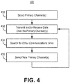
- Figure 4 illustrates one embodiment of a method 400 for utilizing a multichannel transceiver to maintain communications with a vehicle traffic center and/or a vehicle operations center.
- method 400 shown in Figure 4 is described herein as being implemented in the systems shown in Figures 1-3 , it is to be understood that other embodiments can be implemented in other ways.
- the blocks of the flow diagrams have been arranged in a generally sequential manner for ease of explanation; however, it is to be understood that this arrangement is merely exemplary, and it should be recognized that the processing associated with the methods (and the blocks shown in the Figures) can occur in a different order (for example, where at least some of the processing associated with the blocks is performed in parallel and/or in an event-driven manner).
- a primary receive channel and a primary transmit channel e.g. with a communications management system 108 of a multichannel transceiver 110 in a vehicle 101 that corresponds to a primary communications link coupling the vehicle 101 with a vehicle traffic control center 104 and/or a vehicle operations center 106 through a first datalink transceiver station 114A of at least one datalink system 102.
- the primary receive channel and the primary transmit channel may be the same channel and thus on the same frequenc(ies).
- the primary receive channel and the primary transmit channel are different channels and are on different frequencies.
- the primary receive channel and the primary transmit channel are selected based upon the geographic location of the vehicle 101; the signal strength of the signals on a channel received by the vehicle 101 from the at least one datalink network 102 and/or received by the at least one datalink network 102 from the vehicle 101; operational cost of a relay network system; instructions received from a service provider, and/or any other factor, e.g. the factors described above with regards to the selection of the at least one datalink network system and the at least one datalink transceiver station.
- transmit and receive data e.g. messages, between the vehicle 101 and the vehicle traffic control center 104 and/or the vehicle operations center 106 over the primary channel(s).
- transmit and receive data using the multichannel transceiver 110.
- Viable communications links are communications links that can be used to facilitate communications with the vehicle traffic center 104 and/or the vehicle operations center 106.
- the signal characteristic is a signal to noise ratio (SNR) and/or a received signal strength indicator (RSSI).
- select new primary channel(s) for the multichannel transceiver 110 e.g. with the communications management system 108.
- select new channel(s) based upon the new channel(s) corresponding to a new communications link having a signal characteristic better than the primary communications link, the new communications link has a signal characteristic better than a first threshold level, and/or the primary communications link having a signal characteristic below a second threshold level.
- the threshold levels may be SNR and/or RSSI levels.
- Example 1 includes a system, comprising: a multichannel transceiver configured to be installed in a vehicle and to simultaneously receive on at least two channels; wherein the multichannel transceiver is configured to communicate through a datalink system with at least one of a vehicle traffic center and a vehicle operations center; a communications management system coupled to the multichannel transceiver; wherein the communications management system is configured to be installed in a vehicle; and wherein the communications management system is configured to control the channels of the multichannel transceiver, and relay data between vehicle components and the at least one of a vehicle traffic center and the vehicle operations center.
- Example 2 includes the system of Example 1, wherein the multichannel transceiver is configured to be coupled, through a first communications link over a first channel and through a second communications link over a second channel, to a datalink system, where the datalink system comprises: at least one datalink network system; a first datalink transceiver station coupled to the first communications link, and to at least one of the vehicle traffic center and the vehicle operations center through the at least one datalink network system; a second datalink transceiver station coupled to the second communications link, and to the at least one of the vehicle traffic center and the vehicle operations center through the at least one datalink network system; wherein the communications management system is configured to select the first communications link to facilitate communications between the multichannel transceiver and the at least one of the vehicle traffic center and the vehicle operations center; and wherein the communications management system is configured to select the second communications link when communications over the first communications link becomes disrupted.
- the datalink system comprises: at least one datalink network system; a first datalink transceiver station coupled to the first communications link
- Example 3 includes the system of any of Examples 1-2, wherein the multichannel transceiver is configured to be coupled through a first communications link over a first channel and through a second communications link over a second channel, to a datalink system, where the datalink system comprises: at least one datalink network system; a first datalink transceiver station coupled to the first communications link, and to a vehicle traffic center through the at least one datalink network system; and a second datalink transceiver station coupled to the second communications link, and to a vehicle operations center through the at least one datalink network system.
- Example 4 includes the system of any of Examples 1-3, wherein the multichannel transceiver is configured to be coupled through a first communications link over a first channel and through a second communications link over a second channel, to a datalink system, where the datalink system comprises: at least one datalink network system a first datalink transceiver station coupled to the first communications link, and to a vehicle traffic center and a vehicle operations center through the at least one datalink network system; and a second datalink transceiver station coupled to the second communications link, and to a vehicle traffic center and a vehicle operations center through the at least one datalink network system.
- Example 5 includes the system of Example 4, wherein if either the first communications link or the second communications link becomes disrupted, the multichannel transceiver is configured to remain in communications with the vehicle traffic center and the vehicle operations center.
- Example 6 includes the system of any of Examples 1-5, wherein the multichannel transceiver comprises a software defined radio.
- Example 7 includes the system of any of Examples 1-6, further comprising at least one bus coupling the communications management system to the multichannel transceiver.
- Example 8 includes the system of any of Examples 1-7, wherein the communications management system is configured to be coupled to at least one of an inertial management system and a global navigation satellite system receiver.
- Example 9 includes a communications management system, comprising: a processing system; a router coupled to the processing system; wherein the communications management system is configured to be installed in a vehicle and to be coupled to a multichannel transceiver, in the vehicle, configured to simultaneously receive on at least two channels simultaneously; and wherein the processing system is configured to control the channels of the multichannel transceiver, and relay data between components in the vehicle and at least one of a vehicle traffic center and a vehicle operations center.
- a communications management system comprising: a processing system; a router coupled to the processing system; wherein the communications management system is configured to be installed in a vehicle and to be coupled to a multichannel transceiver, in the vehicle, configured to simultaneously receive on at least two channels simultaneously; and wherein the processing system is configured to control the channels of the multichannel transceiver, and relay data between components in the vehicle and at least one of a vehicle traffic center and a vehicle operations center.
- Example 10 includes the communications management system of Example 9, wherein the router comprises at least one of an aircraft communications addressing and reporting system (ACARS) router, an aeronautical telecommunication network (ATN) / open system interconnection (OSI) router, and an Internet Protocol (IP) router such as an ATN/IP router.
- ACARS aircraft communications addressing and reporting system
- ATN aeronautical telecommunication network
- OSI open system interconnection
- IP Internet Protocol
- Example 11 includes the communications management system of any of Examples 9-10, wherein the processing unit comprises: a processor; a memory coupled to the processor; and wherein the memory comprises: a mode control system; a frequency management system; and a data management system.
- the processing unit comprises: a processor; a memory coupled to the processor; and wherein the memory comprises: a mode control system; a frequency management system; and a data management system.
- Example 12 includes the communications management system of any of Examples 9-11, wherein initial frequencies of operation are determined based upon at least one of (a) geographic location; (b) received signal strength; (c) cost; (d) instructions from a service provider, (e) communications link availability, (f) communications link performance, (g) datalink security, and (h) ability to communicate vehicle traffic control safety service messages.
- Example 13 includes the communications management system of any of Examples 9-12, wherein the communications management unit is configured to control the multichannel transceiver to be coupled, through a first communications link over a first channel and through a second communications link over a second channel, to a datalink system, where the datalink system comprises: a first datalink transceiver station coupled to the first communications link, and to at least one of the vehicle traffic center and the vehicle operations center through at least one datalink network system; a second datalink transceiver station coupled to the second communications link, and to the at least one of the vehicle traffic center and the vehicle operations center through the at least one datalink network system; and the at least one datalink network system; wherein the communications management system is configured to select the first communications link to facilitate communications between the multichannel transceiver and the at least one of the vehicle traffic center and the vehicle operations center; and wherein the communications management system is configured to select the second communications link when communications over the first communications link becomes disrupted.
- the communications management unit is configured to control the multichannel transceiver to be
- Example 14 includes the communications management system of any of Examples 9-13, wherein the communications management unit is configured to control the multichannel transceiver to be coupled to a first communications link and a second communications link; wherein the first communications link is coupled to a first datalink transceiver station; wherein the second communications link is coupled to a second datalink transceiver station; wherein the first datalink transceiver station and the second datalink transceiver station are each coupled to at least one datalink network system; wherein at least one datalink network system is coupled to the vehicle traffic center and the vehicle operations center; wherein the vehicle traffic center is coupled to the multichannel transceiver through the first datalink transceiver station; and wherein the vehicle operations center is coupled to the multichannel transceiver through the second datalink transceiver station.
- Example 15 includes the communications management system of any of Examples 9-14, wherein the communications management unit is configured to control the multichannel transceiver to be coupled through a first communications link over a first channel and through a second communications link over a second channel, to a datalink system, where the datalink system comprises: a first datalink transceiver station coupled to the first communications link, and to a vehicle traffic center and a vehicle operations center through at least one datalink network system; a second datalink transceiver station coupled to the second communications link, and to a vehicle traffic center and a vehicle operations center through the at least one datalink network system; and the at least one datalink network system.
- the communications management unit is configured to control the multichannel transceiver to be coupled through a first communications link over a first channel and through a second communications link over a second channel, to a datalink system
- the datalink system comprises: a first datalink transceiver station coupled to the first communications link, and to a vehicle traffic center and a vehicle operations center through at least one data
- Example 16 includes the system of any of Examples 9-15, wherein if either the first communications link or the second communications link becomes disrupted, the multichannel transceiver is configured to remain in communications with the vehicle traffic center and the vehicle operations center.
- Example 17 includes the system of any of Examples 9-16, wherein the communications management system is configured to be coupled to at least one of an inertial management system and a global navigation satellite system receiver.
- Example 18 includes a method, comprising: selecting, with a communications management system configured to be installed on a vehicle, at least one primary channel on a multichannel transceiver; at least one of transmitting and receiving data over the at least one primary channel; searching, with the multichannel transceiver for other viable communications links; and selecting a new at least one primary channel.
- Example 19 includes the method of Example 18, wherein the selecting at least one primary channel comprises selecting a new primary channel based upon at least one of: signal strength of the signals received, geographic location; cost, instructions from a service provider, communications link availability, datalink security, and ability to communicate vehicle traffic control safety service messages.
- Example 20 includes the method of any of Examples 18-19, wherein the selecting the new at least one primary channel comprises selecting a new primary channel based upon at least one of: a communications link corresponding to the new primary channel having a signal characteristic better than a communications link of the primary channel, the communications link corresponding to the new primary channel having a signal characteristic better than a first threshold level, the communications link corresponding to the primary channel having a signal characteristic below a second threshold level, geographic location; cost, instructions from a service provider, communications link availability, datalink security, and ability to communicate vehicle traffic control safety service messages.
Landscapes
- Engineering & Computer Science (AREA)
- Computer Networks & Wireless Communication (AREA)
- Signal Processing (AREA)
- Physics & Mathematics (AREA)
- General Physics & Mathematics (AREA)
- Astronomy & Astrophysics (AREA)
- Aviation & Aerospace Engineering (AREA)
- Computer Security & Cryptography (AREA)
- Mobile Radio Communication Systems (AREA)
- Traffic Control Systems (AREA)
Abstract
Description
- Modern aircraft include three VHF data radios each of which is capable of receiving only a single channel at any time. Two of the radios are dedicated for voice communications and one radio is dedicated to a single channel for data communications. Many such aircraft do not have the capability to add an additional data radio and antenna(s) to support operation of a second data channel. This may arise due to cost, lack of space for the radio, the undesirability of having too many holes in the aircraft body (e.g. to mount additional antenna(s)), drag caused by the additional antenna(s), and interference by having proximate antennas. As a result, all VHF data traffic, such as messages from air traffic controllers and airline operations centers must be conveyed through the single VHF data channel. This is not always feasible or desirable. Therefore, there is a need to provide more robust data communications without increasing the number of radios and antennas on an aircraft.
- In one embodiment, a method is provided. The method comprises: selecting, with a communications management system configured to be installed on a vehicle, at least one primary channel on a multichannel transceiver; transmitting and/or receiving data over the at least one primary channel; searching, with the multichannel transceiver for other viable communications links; and selecting a new at least one primary channel.
- Understanding that the drawings depict only exemplary embodiments and are not therefore to be considered limiting in scope, the exemplary embodiments will be described with additional specificity and detail through the use of the accompanying drawings, in which:
-
Figure 1 illustrates one embodiment of a multichannel vehicle communications system; -
Figure 2 illustrates one embodiment of a method for analyzing vehicle systems during vehicle travel; -
Figure 3 illustrates another embodiment of a multichannel vehicle communications system; and -
Figure 4 illustrates one embodiment of a method for utilizing a multichannel transceiver to maintain communications with a vehicle operations center and/or a vehicle traffic center. - In accordance with common practice, the various described features are not drawn to scale but are drawn to emphasize specific features relevant to the exemplary embodiments. Reference characters denote like elements throughout figures and text.
- The following detailed description is merely exemplary in nature and is not intended to limit the invention or the application and uses of the invention. As used herein, the word "exemplary" means "serving as an example, instance, or illustration." Thus, any embodiment described herein as "exemplary" is not necessarily to be construed as preferred or advantageous over other embodiments. All of the embodiments described herein are exemplary embodiments provided to enable persons skilled in the art to make or use the invention and not to limit the scope of the invention which is defined by the claims. Furthermore, there is no intention to be bound by any expressed or implied theory presented in the preceding background and summary, or the following detailed description.
- For pedagogical purposes, a vehicle may be described hereinafter as an aircraft. However, it is understood that the teachings herein are applicable to other types of vehicles including without limitation space craft, ships, automobiles, buses, trains, and any other vehicle. Thus, a pilot of an aircraft is more generically referred to as an operator of a
vehicle 101. An airline is more generically referred to as an owner of a vehicle. A flight plan of an aircraft is more generically referred to as a travel path of the vehicle. -
Figure 1 illustrates one embodiment of a multichannelvehicle communications system 100. The multichannelvehicle communications system 100 is configured to simultaneously receive communications in two or more channels, e.g. corresponding to two or more communications links. In another embodiment, the multichannelvehicle communications system 100 is also configured to transmit over a single channel, e.g. one communications link, at any time while simultaneously receiving one or more channels. Communications channel, or channel, means a frequency band, e.g. a frequency. - The multichannel
vehicle communications system 100 comprises avehicle 101, adatalink system 102, a vehicle traffic control center (VTC) 104 (e.g. an air traffic control center), and a vehicle operations center (VOC) 106 (e.g. an airline operations center). In one embodiment, thedatalink system 102 is a terrestrial system. Thevehicle 101 includes a communications management system 108 (CMS; also known as a communications management unit) coupled to amultichannel transceiver 110. Themultichannel transceiver 110 is configured to simultaneously (a) receive on at least two channels and (b) transmit on at least one channel. In another embodiment, themultichannel transceiver 110 receives on a second channel, while alternating between simultaneously receiving or transmitting on a first channel. In a further embodiment, the channels are in the VHF band; alternatively the channels may be in other bands. In yet another embodiment, as will be further exemplified, thevehicle traffic center 104 andvehicle operations center 106 are coupled through the same or different datalink network systems to both the firstdatalink transceiver station 114A and the seconddatalink transceiver station 114B, and e.g. thus to thevehicle 101. - The
vehicle 101, e.g. themultichannel transceiver 110, is coupled to thedatalink system 102 by at least two communications links, e.g. afirst communications link 112A and asecond communications link 112B, corresponding to two different channels. Although, twocommunications links Figure 1 and described elsewhere herein, more than two communications links may be used. Themultichannel transceiver 110, and hence thecorresponding communications links 112, may be a HF, VHF, satellite, cellular network, Wi-Fi, Wi-Max, and/or AeroMACs transceiver and corresponding communications links. - Data is communicated between the
vehicle 101 and the vehicletraffic control center 104 and thevehicle operations center 106 through thedatalink system 102. For example, for aircraft, thedatalink system 102 includes datalink transceiver stations and datalink networks, e.g. part of Rockwell Collins' ARINC network and/or SITA's network. In one embodiment, thedatalink system 102 may communicate using an aircraft communications addressing and reporting system (ACARS) protocol, and/or an aeronautical telecommunication network (ATN) / open system interconnection (OSI) and/or an Internet Protocol (IP) protocols. - In one embodiment, the
vehicle 101 can communicate with the vehicletraffic control center 104 and/or thevehicle operations center 106 through at least two different network service providers. For example, the at least onedatalink network system 116 comprises two datalink network systems each of which are operated by different service providers. Each datalink network system is coupled to a unique datalink transceiver station which is also operated by the corresponding service provider. In another embodiment, each datalink network system is coupled to both the vehicletraffic control center 104 and thevehicle operations center 106. Alternatively, in a further embodiment, the vehicletraffic control center 104 and thevehicle operations center 106 are each uniquely coupled to one of the datalink transceiver stations. - The
datalink system 102 includes at least one datalink transceiver station (e.g. a ground datalink transceiver station or ground transceiver station that forms a communications link with thevehicle 101 such as an aircraft) coupled to at least onedatalink network system 116.Figure 1 illustrates one embodiment of adatalink system 102 including a firstdatalink transceiver station 114A and a seconddatalink transceiver station 114B each coupled to the at least onedatalink network system 116. In another embodiment, each datalink transceiver station includes a radio transceiver configured to transmit and receive data respectively to and from thevehicle 101. In a further embodiment, the at least onedatalink network system 116 is a ground network which routes data between thevehicle 101, and the vehicletraffic control center 104 and/or thevehicle operations center 106. - In one embodiment, the first
datalink transceiver station 114A and the seconddatalink transceiver station 114B are operated by the same or different service providers, e.g. Rockwell Collins and/or SITA. In another embodiment, the firstdatalink transceiver station 114A and the seconddatalink transceiver station 114B operate on different channels, e.g. frequencies, even if operated by the same service provider. - In one embodiment, each datalink network system includes one or more routers to facilitate the routing of such data between vehicles, and the
vehicle traffic center 104 and/orvehicle operations center 106. In another embodiment, the one or more routers include an ACARS router, an ATN / OSI router, and/or an IP router such as an ATN/IP router. In a further embodiment, each datalink network system includes one or more communications links that couple the datalink network system to at least one datalink transceiver station, thevehicle traffic center 104 and/or thevehicle operations center 106. - The
datalink system 102 including a firstdatalink transceiver station 114A, a seconddatalink transceiver station 114B, and at least onedatalink network system 116. Thus, the at least onedatalink network system 116 can be a one, two, three, or more datalink networks. In one embodiment, thedatalink system 102 includes three or more datalink transceiver stations. -
Figure 2 illustrates one embodiment of avehicle 201 including amultichannel transceiver 210. Thevehicle 201 comprises the communications management system (CMS) 208 coupled to themultichannel transceiver 210. In another embodiment, thecommunications management system 208 is coupled to themultichannel transceiver 210 by at least one bus 209, e.g. a data bus. In another embodiment, the at least one bus 209 is one or more ARINC 429 buses. - In one embodiment, the
vehicle 201 includes at least onesensor 207 which may be an inertial management unit and/or a global satellite navigation system, e.g. GPS, receiver. In another embodiment, the at least onesensor 207 is coupled to thecommunications management system 208, e.g. through the at least one bus 209. - In one embodiment, the
multichannel transceiver 210 includes areceiver 210A andtransmitter 210B coupled to anantenna 210C. Thereceiver 210A and thetransmitter 210B may be coupled to theantenna 210C in different ways, e.g. to reduce interference in thereceiver 210B from simultaneous transmission by thetransmitter 210B. In another embodiment, theantenna 210C may comprise a transmit antenna and a receive antenna which are respectively coupled to thetransmitter 210B and thereceiver 210A. Alternatively or in addition, a portion of a transmission signal and/or wideband noise generated by thetransmitter 210B may be fed back to an interference canceller in thereceiver 210A to suppress interference arising from the transmission signal an/or the wideband noise. - In one embodiment, the
receiver 210A, or thereceiver 210A and thetransmitter 210B, are software defined radios. In another embodiment, the software defined radio receiver includes a low noise amplifier coupled to an analog to digital converter (ADC); the ADC is coupled to a digital signal processor (DSP). In a further embodiment, the software defined radio transmitter includes a DSP coupled to a digital to analog converter (DAC); the DAC is coupled to a power amplifier. In yet another embodiment, a software defined radio receiver and transmitter share a common DSP. - The
multichannel transceiver 210 is configured to simultaneously receive communications in two or more channels, e.g. corresponding to two or more communications links. In one embodiment, themultichannel transceiver 210 is also configured to transmit over a single channel, e.g. one communications link, at any time while simultaneously receiving one or more communications channels. In another embodiment, if the power amplifier is linear enough to avoid creating interference, e.g. intermodulation distortion products, themultichannel transceiver 210 is also configure to transmit two or more channels simultaneously, even while thereceiver 210A is receiving on other channels. In a further embodiment, the power amplifier can be linearized by using pre-distortion. - In one embodiment, the
communications management system 208 comprises aprocessing system 208A. In another embodiment, theprocessing system 208A includes amemory 208B coupled to aprocessor 208C. In a further embodiment, thememory 208B includes adatalink management system 208D. In yet another embodiment, thedatalink management system 208D includes amode control system 208D-1, afrequency management system 208D-2, and adata management system 208D-3. - In one embodiment, the
processor 208C andmemory 208B comprise in whole or in part a state machine or a field programmable gate array. In another embodiment, thedatalink management system 208D, including its constituents, is software stored in thememory 208B that is executed by theprocessor 208C. - In one embodiment, the
communications management system 208 routes messages through at least onedatalink system 102 between components of thevehicle 101, and theVTC 104 andVOC 106. Vehicle components including thecommunications management system 208 itself and other components such as travel management system (or flight management system for aircraft) and a central maintenance computer. - In yet a further embodiment, the
communications management system 208 includes at least onerouter 208E which performs the routing function in thecommunications management system 208. In one embodiment, the at least onerouter 208E includes an ACARS router, an ATN/OSI router, and/or an IP router such as an ATN/IP router. In another embodiment, thecommunications management system 208 controls and sets the frequencies, e.g. of the channels to facilitate reception and transmission, of themultichannel transceiver 210; in other words, thecommunications management system 208 controls the channels used by themultichannel transceiver 210. - In one embodiment, the
datalink management system 208D provides mode control, frequency management and data management services as shall be further described. In another embodiment, thedatalink management system 208D selects at least one datalink network system and at least one datalink transceiver station through which to send and receive data, e.g. messages, respectively to and from a vehicletraffic control center 104 and/or avehicle operations center 106. In a further embodiment, thedatalink management system 208D selects the at least one datalink network system and the at least one datalink transceiver station based on cost (e.g. costs of different service providers), communications link availability, communications link performance, datalink security, ability to communicate vehicle traffic control safety service messages, instructions from a service provider, and/or other factors, e.g. as described elsewhere herein. - The
mode control system 208D-1 determines the mode of operation of themultichannel transceiver 210, e.g. voice or data, and/or the corresponding modulation format. In another embodiment, themode control system 208D-1 also determines the rate at which data is send and received by themultichannel transceiver 210. In a further embodiment, for a VHF radio, the data modes include Mode A, andMode 2 which operates at a higher data rate of 32 kbps. - In one embodiment, the
frequency management system 208D-2 determines the frequencies or channels through which the multichannel transceiver receives and/or transmits, e.g. through at least onedatalink system 102 to a vehicletraffic control center 104 and avehicle operations center 106. In another embodiment, thefrequency management system 208D-2 stores different sets of frequencies, for different geographic regions, used to communicate with ground datalink stations coupled to vehicle traffic control centers 104 and vehicle operations centers 106. - In one embodiment, the
data management system 208D-3 determines whichcommunications links 112 and datalink network system(s) 116 will be used to transmit and receive messages from vehicle traffic control centers 104 and vehicle operations centers 106. Thedata management system 208D-3 also assembles and dissembles messages based on industry standards, e.g. ARINC 618, including into blocks or Internet Protocol packets. - In one embodiment, the
data management system 208D-3 determines the geographic location of thevehicle 201 from the at least onesensor 207. In another embodiment, thedata management system 208D-3 selects the at least one datalink network system and the at least one datalink transceiver station in the geographic region based upon, e.g., the factors described above with regards to the selection of the at least one datalink network system and the at least one datalink transceiver station. In a further embodiment, thedata management system 208D-3 provides geographic region, the selected at least one datalink network system, and/or the selected at least one datalink transceiver station to thefrequency management system 208D-2. In yet another embodiment, thefrequency management system 208D-2 selects the corresponding set of frequencies for the selected at least one datalink network system and the at least one datalink transceiver station based upon the geographic region, the selected at least one datalink network system, and/or the selected at least one datalink transceiver station. In another embodiment, thefrequency management system 208D-2 then commands themultichannel transceiver 210 to tune to the selected set of frequencies to communicate with the selected at least one datalink network system and the at least one datalink transceiver station. For example, thefrequency management system 208D-2 commands thereceiver 210A to receive signals on two channels (or frequencies) respectively corresponding to a vehicle traffic control center 104 (and a firstdatalink transceiver station 114A) and a vehicle operations center 106 (and a seconddatalink transceiver station 114B); thefrequency management system 208D-2 tunes thetransmitter 210B to either the frequency corresponding to the vehicletraffic control center 104 or thevehicle operations center 106 depending upon to which end point themultichannel transceiver 210 is transmitting. - In one embodiment, the
multichannel transceiver 210 is used to establish at least two channels with the vehicletraffic control center 104 and thevehicle operations center 106 through at least two communications links, at least two datalink transceiver stations, and at least onedatalink network system 116. In this embodiment, data, e.g. messages, are transmitted to and received from both the vehicletraffic control center 104 and thevehicle operations center 106 over the first channel and first communications link 112A. Until commanded otherwise, thetransmitter 210B transmits to the firstdatalink transceiver station 114A through thefirst communications channel 112A. The second channel and second communications link 112B also permits transmission to and reception from both the vehicletraffic control center 104 and thevehicle operations center 106, but are backups only used in the event communications are disrupted over the first channel and the first communications link 112A. Such disruption may occur when thevehicle 101 leaves the operating range of the firstdatalink transceiver station 114A, because the firstdatalink transceiver station 114A becomes disabled, or because an interfering signal makes transmission to or reception from the firstdatalink transceiver station 114A unreliable. - In one embodiment, if the
communications management system 208, e.g. thedatalink manager 208D, detects such disrupted communications, e.g. due to no acknowledgements for messages being received, then thecommunications management system 208 commands thetransmitter 210B to alter its frequency of transmission from a frequency of the first communications link 114A to a frequency of the second communications link 114B. Further, thereceiver 210A andcommunications management system 208 will begin utilizing data, e.g. messages, received through the second communications channel and the second communications link 114B. In another embodiment, thecommunications management system 208 then selects a new first channel and first communications link 114A to serve as a backup for the second channel and second communications link 114A which have become the primary channel and communications link. - In one embodiment, the
multichannel transceiver 210 is used to establish at least twocommunications links 112 with at least two datalink transceiver stations, at least onedatalink system 116, and the vehicletraffic control center 104 and thevehicle operations center 106. In this embodiment, messages are transmitted to and received from both the vehicletraffic control center 104 and thevehicle operations center 106 respectively over a first communications channel and the first communications link 112A, and a second channel and the second communications link 112B. Thus, the firstdatalink transceiver station 114A transmits and receives messages to and from the vehicletraffic control center 104 over the first channel and the first communications link 112A; the seconddatalink transceiver station 114B transmits and receives messages to and from theVOC 106 over the second channel and the second communications link 112B. In this embodiment, thereceiver 210A simultaneous receives and processes messages received over the first communications link 112A and the second communications link 122B. Thetransmitter 210B transmits messages through the first communications link 112A and the second communications link 122B one communications link at a time. This approach has the benefit of reducing message congestion on each of the communications links, and effectively increasing communications bandwidth. - In one embodiment, the
multichannel transceiver 210 receives information simultaneously from one or both of the vehicletraffic control center 104 and thevehicle operations center 106 over both the first communications link 112A and a first channel, and the second communications link 112B and the second channel. This approach also has the benefit of reducing message congestion, and effectively increasing communications bandwidth. -
Figure 3 illustrates another embodiment of a multichannelvehicle communications system 300. The multichannelvehicle communications system 300 is configured to be able to simultaneously receive communications over two or more communications links. In one embodiment, the multichannelvehicle communications system 300 is also configured to transmit over a communications link while receiving over one or more other communications links. - The multichannel
vehicle communications system 300 comprises avehicle 301, adatalink system 302, a vehicle traffic control center (VTC) 304 (e.g. an air traffic control center), and a vehicle operations center (VOC) 306 (e.g. an airlines operations center). Thevehicle 301 includes acommunications management system 308 coupled to amultichannel transceiver 310. Thevehicle 301 is coupled thedatalink system 302 by at least two communications links, e.g. a first communications link 312A and a second communications link 312B. Although, twocommunications links Figure 3 and described elsewhere herein, more than two communications links may be used. Each communications link may be a HF, VHF, satellite, cellular network, Wi-Fi, Wi-Max, an AeroMACs, and/or any other communications links. - The
datalink system 302 includes at least two datalink transceiver stations (e.g. ground datalink transceiver station or ground transceiver station each of which forms a communications link between thevehicle 301 and a datalink network system.Figure 3 illustrates one embodiment of adatalink system 302 including a firstdatalink transceiver station 314A and a seconddatalink transceiver station 314B each of which is respectively coupled to a firstdatalink network system 316A and a seconddatalink network system 316B. However, thedatalink system 302 can include more than two pairs of datalink transceiver stations and datalink network systems. In another embodiment, each datalink transceiver station includes a radio transceiver configured to transmit and receive data from thevehicle 301. In a further embodiment, each datalink network is a ground network which routes data to and from thevehicle 301 to the vehicletraffic control center 304 and/or thevehicle operations center 306. Each datalink network includes one or more routers to facilitate the routing of such data. - In this embodiment, the
receiver 210A is simultaneously coupled (a) through the first communications link 312A to the firstdatalink transceiver station 314A, the firstdatalink network system 316A, and the vehicletraffic control center 304, and (b) through the second communications link 312B to the seconddatalink transceiver station 314B, the seconddatalink network system 316B, and thevehicle operations center 306. In another embodiment, thetransmitter 210B transmits on the frequenc(ies) of the first channel. Upon the first communications link 312A becoming disrupted, thecommunications management system 308 commands themultichannel transceiver 310 to re-establish another communications link via different frequenc(ies) for the first channel while continuously transmitting and receiving on the frequenc(ies) of the second channel. -
Figure 4 illustrates one embodiment of amethod 400 for utilizing a multichannel transceiver to maintain communications with a vehicle traffic center and/or a vehicle operations center. To the extent that the embodiment ofmethod 400 shown inFigure 4 is described herein as being implemented in the systems shown inFigures 1-3 , it is to be understood that other embodiments can be implemented in other ways. The blocks of the flow diagrams have been arranged in a generally sequential manner for ease of explanation; however, it is to be understood that this arrangement is merely exemplary, and it should be recognized that the processing associated with the methods (and the blocks shown in the Figures) can occur in a different order (for example, where at least some of the processing associated with the blocks is performed in parallel and/or in an event-driven manner). - In
block 430, select a primary receive channel and a primary transmit channel, e.g. with acommunications management system 108 of amultichannel transceiver 110 in avehicle 101 that corresponds to a primary communications link coupling thevehicle 101 with a vehicletraffic control center 104 and/or avehicle operations center 106 through a firstdatalink transceiver station 114A of at least onedatalink system 102. In one embodiment, the primary receive channel and the primary transmit channel may be the same channel and thus on the same frequenc(ies). In another embodiment, the primary receive channel and the primary transmit channel are different channels and are on different frequencies. In a further embodiment, the primary receive channel and the primary transmit channel are selected based upon the geographic location of thevehicle 101; the signal strength of the signals on a channel received by thevehicle 101 from the at least onedatalink network 102 and/or received by the at least onedatalink network 102 from thevehicle 101; operational cost of a relay network system; instructions received from a service provider, and/or any other factor, e.g. the factors described above with regards to the selection of the at least one datalink network system and the at least one datalink transceiver station. Inblock 432, transmit and receive data, e.g. messages, between thevehicle 101 and the vehicletraffic control center 104 and/or thevehicle operations center 106 over the primary channel(s). In one embodiment, transmit and receive data using themultichannel transceiver 110. In another embodiment, send messages in ACARS, ATN/OSI and/or ATN/IP formats. - In
block 434, scan, e.g. with themultichannel transceiver 110, other receive channels searching from other viable communications links coupled to the vehicletraffic control center 104 and/or thevehicle operations center 106 that have better signal characteristics then the primary communications link. Viable communications links are communications links that can be used to facilitate communications with thevehicle traffic center 104 and/or thevehicle operations center 106. In one embodiment, the signal characteristic is a signal to noise ratio (SNR) and/or a received signal strength indicator (RSSI). - In
block 436, select new primary channel(s) for themultichannel transceiver 110, e.g. with thecommunications management system 108. In one embodiment select new channel(s) based upon the new channel(s) corresponding to a new communications link having a signal characteristic better than the primary communications link, the new communications link has a signal characteristic better than a first threshold level, and/or the primary communications link having a signal characteristic below a second threshold level. In another embodiment, the threshold levels may be SNR and/or RSSI levels. In a further embodiment, communicate over both the original primary channel(s) and the new primary channel(s). Then, return to block 434. - Example 1 includes a system, comprising: a multichannel transceiver configured to be installed in a vehicle and to simultaneously receive on at least two channels; wherein the multichannel transceiver is configured to communicate through a datalink system with at least one of a vehicle traffic center and a vehicle operations center; a communications management system coupled to the multichannel transceiver; wherein the communications management system is configured to be installed in a vehicle; and wherein the communications management system is configured to control the channels of the multichannel transceiver, and relay data between vehicle components and the at least one of a vehicle traffic center and the vehicle operations center.
- Example 2 includes the system of Example 1, wherein the multichannel transceiver is configured to be coupled, through a first communications link over a first channel and through a second communications link over a second channel, to a datalink system, where the datalink system comprises: at least one datalink network system; a first datalink transceiver station coupled to the first communications link, and to at least one of the vehicle traffic center and the vehicle operations center through the at least one datalink network system; a second datalink transceiver station coupled to the second communications link, and to the at least one of the vehicle traffic center and the vehicle operations center through the at least one datalink network system; wherein the communications management system is configured to select the first communications link to facilitate communications between the multichannel transceiver and the at least one of the vehicle traffic center and the vehicle operations center; and wherein the communications management system is configured to select the second communications link when communications over the first communications link becomes disrupted.
- Example 3 includes the system of any of Examples 1-2, wherein the multichannel transceiver is configured to be coupled through a first communications link over a first channel and through a second communications link over a second channel, to a datalink system, where the datalink system comprises: at least one datalink network system; a first datalink transceiver station coupled to the first communications link, and to a vehicle traffic center through the at least one datalink network system; and a second datalink transceiver station coupled to the second communications link, and to a vehicle operations center through the at least one datalink network system.
- Example 4 includes the system of any of Examples 1-3, wherein the multichannel transceiver is configured to be coupled through a first communications link over a first channel and through a second communications link over a second channel, to a datalink system, where the datalink system comprises: at least one datalink network system a first datalink transceiver station coupled to the first communications link, and to a vehicle traffic center and a vehicle operations center through the at least one datalink network system; and a second datalink transceiver station coupled to the second communications link, and to a vehicle traffic center and a vehicle operations center through the at least one datalink network system.
- Example 5 includes the system of Example 4, wherein if either the first communications link or the second communications link becomes disrupted, the multichannel transceiver is configured to remain in communications with the vehicle traffic center and the vehicle operations center.
- Example 6 includes the system of any of Examples 1-5, wherein the multichannel transceiver comprises a software defined radio.
- Example 7 includes the system of any of Examples 1-6, further comprising at least one bus coupling the communications management system to the multichannel transceiver.
- Example 8 includes the system of any of Examples 1-7, wherein the communications management system is configured to be coupled to at least one of an inertial management system and a global navigation satellite system receiver.
- Example 9 includes a communications management system, comprising: a processing system; a router coupled to the processing system; wherein the communications management system is configured to be installed in a vehicle and to be coupled to a multichannel transceiver, in the vehicle, configured to simultaneously receive on at least two channels simultaneously; and wherein the processing system is configured to control the channels of the multichannel transceiver, and relay data between components in the vehicle and at least one of a vehicle traffic center and a vehicle operations center.
- Example 10 includes the communications management system of Example 9, wherein the router comprises at least one of an aircraft communications addressing and reporting system (ACARS) router, an aeronautical telecommunication network (ATN) / open system interconnection (OSI) router, and an Internet Protocol (IP) router such as an ATN/IP router.
- Example 11 includes the communications management system of any of Examples 9-10, wherein the processing unit comprises: a processor; a memory coupled to the processor; and wherein the memory comprises: a mode control system; a frequency management system; and a data management system.
- Example 12 includes the communications management system of any of Examples 9-11, wherein initial frequencies of operation are determined based upon at least one of (a) geographic location; (b) received signal strength; (c) cost; (d) instructions from a service provider, (e) communications link availability, (f) communications link performance, (g) datalink security, and (h) ability to communicate vehicle traffic control safety service messages.
- Example 13 includes the communications management system of any of Examples 9-12, wherein the communications management unit is configured to control the multichannel transceiver to be coupled, through a first communications link over a first channel and through a second communications link over a second channel, to a datalink system, where the datalink system comprises: a first datalink transceiver station coupled to the first communications link, and to at least one of the vehicle traffic center and the vehicle operations center through at least one datalink network system; a second datalink transceiver station coupled to the second communications link, and to the at least one of the vehicle traffic center and the vehicle operations center through the at least one datalink network system; and the at least one datalink network system; wherein the communications management system is configured to select the first communications link to facilitate communications between the multichannel transceiver and the at least one of the vehicle traffic center and the vehicle operations center; and wherein the communications management system is configured to select the second communications link when communications over the first communications link becomes disrupted.
- Example 14 includes the communications management system of any of Examples 9-13, wherein the communications management unit is configured to control the multichannel transceiver to be coupled to a first communications link and a second communications link; wherein the first communications link is coupled to a first datalink transceiver station; wherein the second communications link is coupled to a second datalink transceiver station; wherein the first datalink transceiver station and the second datalink transceiver station are each coupled to at least one datalink network system; wherein at least one datalink network system is coupled to the vehicle traffic center and the vehicle operations center; wherein the vehicle traffic center is coupled to the multichannel transceiver through the first datalink transceiver station; and wherein the vehicle operations center is coupled to the multichannel transceiver through the second datalink transceiver station.
- Example 15 includes the communications management system of any of Examples 9-14, wherein the communications management unit is configured to control the multichannel transceiver to be coupled through a first communications link over a first channel and through a second communications link over a second channel, to a datalink system, where the datalink system comprises: a first datalink transceiver station coupled to the first communications link, and to a vehicle traffic center and a vehicle operations center through at least one datalink network system; a second datalink transceiver station coupled to the second communications link, and to a vehicle traffic center and a vehicle operations center through the at least one datalink network system; and the at least one datalink network system.
- Example 16 includes the system of any of Examples 9-15, wherein if either the first communications link or the second communications link becomes disrupted, the multichannel transceiver is configured to remain in communications with the vehicle traffic center and the vehicle operations center.
- Example 17 includes the system of any of Examples 9-16, wherein the communications management system is configured to be coupled to at least one of an inertial management system and a global navigation satellite system receiver.
- Example 18 includes a method, comprising: selecting, with a communications management system configured to be installed on a vehicle, at least one primary channel on a multichannel transceiver; at least one of transmitting and receiving data over the at least one primary channel; searching, with the multichannel transceiver for other viable communications links; and selecting a new at least one primary channel.
- Example 19 includes the method of Example 18, wherein the selecting at least one primary channel comprises selecting a new primary channel based upon at least one of: signal strength of the signals received, geographic location; cost, instructions from a service provider, communications link availability, datalink security, and ability to communicate vehicle traffic control safety service messages.
- Example 20 includes the method of any of Examples 18-19, wherein the selecting the new at least one primary channel comprises selecting a new primary channel based upon at least one of: a communications link corresponding to the new primary channel having a signal characteristic better than a communications link of the primary channel, the communications link corresponding to the new primary channel having a signal characteristic better than a first threshold level, the communications link corresponding to the primary channel having a signal characteristic below a second threshold level, geographic location; cost, instructions from a service provider, communications link availability, datalink security, and ability to communicate vehicle traffic control safety service messages.
- Although specific embodiments have been illustrated and described herein, it will be appreciated by those of ordinary skill in the art that any arrangement, which is calculated to achieve the same purpose, may be substituted for the specific embodiments shown. Therefore, it is manifestly intended that this invention be limited only by the claims and the equivalents thereof.
Claims (10)
- A system, comprising:a multichannel transceiver (110) configured to be installed in a vehicle (101) and to simultaneously receive on at least two channels;wherein the multichannel transceiver (110) is configured to communicate through a datalink system (102) with at least one of a vehicle traffic center (104) and a vehicle operations center (106);a communications management system (108) coupled to the multichannel transceiver (110);wherein the communications management system (108) is configured to be installed in a vehicle (101); andwherein the communications management system (108) is configured to control the channels of the multichannel transceiver (110), and relay data between vehicle components and the at least one of a vehicle traffic center (104) and the vehicle operations center (106).
- The system of claim 1, wherein the multichannel transceiver (110) is configured to be coupled, through a first communications link (112A) over a first channel and through a second communications link (112B) over a second channel, to a datalink system (102) where the datalink system (102) comprises:at least one datalink network system (116);a first datalink transceiver station (116A) coupled to the first communications link, and to at least one of the vehicle traffic center (104) and the vehicle operations center (106) through the at least one datalink network system (116);a second datalink transceiver station (116B) coupled to the second communications link, and to the at least one of the vehicle traffic center (104) and the vehicle operations center (106) through the at least one datalink network system;wherein the communications management system (108) is configured to select the first communications link (112A) to facilitate communications between the multichannel transceiver (110) and the at least one of the vehicle traffic center (104) and the vehicle operations center (106); andwherein the communications management system (108) is configured to select the second communications link (112B) when communications over the first communications link becomes disrupted.
- The system of claim 1, wherein the multichannel transceiver (110) is configured to be coupled through a first communications link (112A) over a first channel and through a second communications link (112B) over a second channel, to a datalink system (102) , where the datalink system (102) comprises:at least on datalink network system (116);a first datalink transceiver station (114A) coupled to the first communications link (112A), and to a vehicle traffic center (104) through the at least one datalink network system (116); anda second datalink transceiver station (114B) coupled to the second communications link (112B), and to a vehicle operations center (106) through the at least one datalink network system (116).
- The system of claim 1, wherein the multichannel transceiver (110) is configured to be coupled through a first communications link (112A) over a first channel and through a second communications link (112B) over a second channel, to a datalink system (102), where the datalink system (102) comprises:at least one datalink network system (116)a first datalink transceiver station (114A) coupled to the first communications link (112A), and to a vehicle traffic center (104) and a vehicle operations center (106) through the at least one datalink network system (116); anda second datalink transceiver station (114B) coupled to the second communications link (112B), and to a vehicle traffic center (104) and a vehicle operations center (106) through the at least one datalink network system (116).
- The system of claim 4, wherein if either the first communications link (112A) or the second communications link (112B) becomes disrupted, the multichannel transceiver (110) is configured to remain in communications with the vehicle traffic center (104) and the vehicle operations center (106).
- The system of claim 1, wherein the multichannel transceiver (110) comprises a software defined radio.
- The system of claim 1, further comprising at least one bus (209) coupling the communications management system (208) to the multichannel transceiver (210).
- A method, comprising:selecting, with a communications management system configured to be installed on a vehicle, at least one primary channel on a multichannel transceiver (430);at least one of transmitting and r receiving data over the at least one primary channel (432);searching, with the multichannel transceiver for other viable communications links (434); andselecting a new at least one primary channel (436).
- The method of claim 8, wherein the selecting at least one primary channel (430) comprises selecting a new primary channel based upon at least one of: signal strength of the signals received, geographic location; cost, instructions from a service provider, communications link availability, datalink security, and ability to communicate vehicle traffic control safety service messages.
- The method of claim 8, wherein the selecting the new at least one primary channel (436) comprises selecting a new primary channel based upon at least one of: a communications link corresponding to the new primary channel having a signal characteristic better than a communications link of the primary channel, the communications link corresponding to the new primary channel having a signal characteristic better than a first threshold level, the communications link corresponding to the primary channel having a signal characteristic below a second threshold level, geographic location; cost, instructions from a service provider, communications link availability, datalink security, and ability to communicate vehicle traffic control safety service messages.
Applications Claiming Priority (1)
| Application Number | Priority Date | Filing Date | Title |
|---|---|---|---|
| US15/600,249 US10491291B2 (en) | 2017-05-19 | 2017-05-19 | System and method for multi-channel vehicle communications |
Publications (2)
| Publication Number | Publication Date |
|---|---|
| EP3404850A1 true EP3404850A1 (en) | 2018-11-21 |
| EP3404850B1 EP3404850B1 (en) | 2025-03-12 |
Family
ID=62217752
Family Applications (1)
| Application Number | Title | Priority Date | Filing Date |
|---|---|---|---|
| EP18171724.0A Active EP3404850B1 (en) | 2017-05-19 | 2018-05-10 | System and method for multi-channel vehicle communications |
Country Status (4)
| Country | Link |
|---|---|
| US (1) | US10491291B2 (en) |
| EP (1) | EP3404850B1 (en) |
| CN (1) | CN108964739B (en) |
| DE (1) | DE202018006942U1 (en) |
Families Citing this family (24)
| Publication number | Priority date | Publication date | Assignee | Title |
|---|---|---|---|---|
| US12040779B2 (en) | 2020-04-20 | 2024-07-16 | Murata Manufacturing Co., Ltd. | Small transversely-excited film bulk acoustic resonators with enhanced Q-factor |
| US11509279B2 (en) | 2020-07-18 | 2022-11-22 | Resonant Inc. | Acoustic resonators and filters with reduced temperature coefficient of frequency |
| US12088281B2 (en) | 2021-02-03 | 2024-09-10 | Murata Manufacturing Co., Ltd. | Transversely-excited film bulk acoustic resonator with multi-mark interdigital transducer |
| US11936358B2 (en) | 2020-11-11 | 2024-03-19 | Murata Manufacturing Co., Ltd. | Transversely-excited film bulk acoustic resonator with low thermal impedance |
| CN109559568A (en) * | 2018-12-14 | 2019-04-02 | 中电科(德阳广汉)特种飞机系统工程有限公司 | Blank pipe method, apparatus, system and the readable storage medium storing program for executing of navigation aircraft |
| US11264969B1 (en) | 2020-08-06 | 2022-03-01 | Resonant Inc. | Transversely-excited film bulk acoustic resonator comprising small cells |
| US11271539B1 (en) | 2020-08-19 | 2022-03-08 | Resonant Inc. | Transversely-excited film bulk acoustic resonator with tether-supported diaphragm |
| US11405017B2 (en) | 2020-10-05 | 2022-08-02 | Resonant Inc. | Acoustic matrix filters and radios using acoustic matrix filters |
| DE102021129427B4 (en) | 2020-11-13 | 2026-03-12 | Murata Manufacturing Co., Ltd. | Manufacturing of XBAR devices from which excess piezoelectric material has been removed. |
| US11816937B2 (en) | 2020-11-18 | 2023-11-14 | Honeywell International Inc. | Systems and methods for reconfigurable on-vehicle data routing |
| US11239816B1 (en) | 2021-01-15 | 2022-02-01 | Resonant Inc. | Decoupled transversely-excited film bulk acoustic resonators |
| US12463615B2 (en) | 2021-01-21 | 2025-11-04 | Murata Manufacturing Co., Ltd | Transversely-excited film bulk acoustic resonators with improved coupling and reduced energy leakage |
| US12308825B2 (en) | 2021-02-12 | 2025-05-20 | Murata Manufacturing Co., Ltd | Transversely-excited film bulk acoustic resonators with narrow gaps between busbars and ends of interdigital transducer fingers |
| US20220262262A1 (en) * | 2021-02-18 | 2022-08-18 | Honeywell International Inc. | Vehicle traffic control communication system |
| US12160220B2 (en) | 2021-04-30 | 2024-12-03 | Murata Manufacturing Co., Ltd. | Transversely-excited film bulk acoustic resonator with oxide strip acoustic confinement structures |
| DE102022111162A1 (en) | 2021-05-07 | 2022-11-10 | Resonant Inc. | TRANSVERSAL EXCITED FILM VOLUME RESONATOR ACOUSTIC MATRIX FILTERS WITH INPUT AND OUTPUT IMPEDANCES MATCHED TO RADIO FREQUENCY FRONTEND ELEMENTS |
| CN115441847A (en) | 2021-06-03 | 2022-12-06 | 谐振公司 | Low-loss transverse-excitation film bulk acoustic resonator and filter |
| CN113380074B (en) * | 2021-08-13 | 2021-11-05 | 中国民用航空总局第二研究所 | Navigation low-altitude monitoring system and method |
| CN113890587B (en) * | 2021-09-28 | 2023-06-23 | 浙江嘉兴数字城市实验室有限公司 | BDS short message-based vehicle safety information data exchange method |
| WO2023081769A1 (en) | 2021-11-04 | 2023-05-11 | Resonant Inc. | Stacked die transversely-excited film bulk acoustic resonator (xbar) filters |
| WO2023097182A1 (en) | 2021-11-23 | 2023-06-01 | Murata Manufacturing Co., Ltd. | Filters using decoupled transversely-excited film bulk acoustic resonators |
| CN118369852A (en) | 2021-12-09 | 2024-07-19 | 株式会社村田制作所 | Filter using a laterally excited film bulk acoustic resonator with inductively coupled sub-resonators |
| CN118355604A (en) | 2021-12-09 | 2024-07-16 | 株式会社村田制作所 | Decoupled Laterally Excited Film Bulk Acoustic Resonator for High-Power Filters |
| WO2023129921A1 (en) | 2021-12-28 | 2023-07-06 | Murata Manufacturing Co., Ltd. | Transatirsely-excited film bulk acoustic resonators with gap dielectric stripes in busbar-electrode gaps |
Citations (6)
| Publication number | Priority date | Publication date | Assignee | Title |
|---|---|---|---|---|
| US6567395B1 (en) * | 1999-03-10 | 2003-05-20 | Rockwell Collins, Inc. | Display for a high frequency (HF) radio |
| CA2492683A1 (en) * | 2002-04-24 | 2003-11-06 | Teledyne Technologies Incorporated | Aircraft data communication system and method |
| EP2129006A2 (en) * | 2008-05-29 | 2009-12-02 | Honeywell International Inc. | Reconfigurable aircraft communications system with integrated avionics communication router and audio management functions |
| US20140003335A1 (en) * | 2012-06-29 | 2014-01-02 | Honeywell International Inc. | Stateful connectionless overlay protocol for information transfer across multiple datalinks |
| EP2876815A2 (en) * | 2013-10-29 | 2015-05-27 | Honeywell International Inc. | Reduced aircraft vhf communication antennas using multi-channel vhf radios |
| EP2899943A1 (en) * | 2014-01-28 | 2015-07-29 | The Boeing Company | Secure aircraft data transmission using multiple communication channels |
Family Cites Families (18)
| Publication number | Priority date | Publication date | Assignee | Title |
|---|---|---|---|---|
| US7331792B2 (en) * | 2002-09-18 | 2008-02-19 | Stoneridge Control Devices, Inc. | Trailer tow connector assembly |
| US7221290B2 (en) | 2004-08-24 | 2007-05-22 | Burgemeister Alvin H | Packetized voice communication method and system |
| US7894779B2 (en) | 2006-06-22 | 2011-02-22 | Honeywell International Inc. | Apparatus and method for transmitting and receiving multiple radio signals over a single antenna |
| US20080084861A1 (en) | 2006-10-10 | 2008-04-10 | Honeywell International Inc. | Avionics communication system and method utilizing multi-channel radio technology and a shared data bus |
| US7876259B2 (en) * | 2006-11-06 | 2011-01-25 | Leonard Schuchman | Automatic dependent surveillance system secure ADS-S |
| US8385288B2 (en) * | 2008-08-20 | 2013-02-26 | Qualcomm Incorporated | Multi-channel SDMA |
| US20110255506A1 (en) | 2010-04-19 | 2011-10-20 | Honeywell International Inc. | Systems and methods for integration of ip-based data link management in existing avionics architectures |
| KR101225183B1 (en) * | 2010-11-08 | 2013-01-22 | 한국전자통신연구원 | Method and apparatus for operating multi-channel based on wireless access for vehicular environment |
| KR20120119430A (en) * | 2011-04-21 | 2012-10-31 | 삼성디스플레이 주식회사 | Organic light emitting display device |
| US8923167B2 (en) | 2011-09-27 | 2014-12-30 | Google Technology Holdings LLC | Communication device for simultaneous transmission by multiple transceivers |
| US8654869B2 (en) * | 2011-10-27 | 2014-02-18 | Cooper Technologies Company | Multi-path radio transmission input/output devices, network, systems and methods with link suitability determination |
| US9285472B2 (en) | 2011-12-06 | 2016-03-15 | L-3 Communications Avionics Systems, Inc. | Multi-link transponder for aircraft and method of providing multi-link transponder capability to an aircraft having an existing transponder |
| JP6031460B2 (en) | 2014-02-06 | 2016-11-24 | 富士重工業株式会社 | Vehicle communication device |
| FR3018622B1 (en) | 2014-03-17 | 2016-04-08 | Rockwell Collins France | FREQUENCY MANAGEMENT METHOD AND COMMUNICATION DEVICE IN AN AIRBORNE PLATFORM |
| US9667338B2 (en) * | 2014-10-17 | 2017-05-30 | The Boeing Company | Multiband wireless data transmission between aircraft and ground systems |
| FR3038464A1 (en) * | 2015-06-30 | 2017-01-06 | Souriau | METHOD FOR MOUNTING A PRESSURE INSERTED MULTICONTACT CONNECTOR |
| US10243646B2 (en) * | 2015-08-17 | 2019-03-26 | The Mitre Corporation | Performance-based link management communications |
| US10986028B2 (en) * | 2016-03-05 | 2021-04-20 | Ge Aviation Systems, Llc | Aircraft message routing system |
-
2017
- 2017-05-19 US US15/600,249 patent/US10491291B2/en active Active
-
2018
- 2018-05-10 EP EP18171724.0A patent/EP3404850B1/en active Active
- 2018-05-10 DE DE202018006942.6U patent/DE202018006942U1/en active Active
- 2018-05-18 CN CN201810479602.8A patent/CN108964739B/en active Active
Patent Citations (6)
| Publication number | Priority date | Publication date | Assignee | Title |
|---|---|---|---|---|
| US6567395B1 (en) * | 1999-03-10 | 2003-05-20 | Rockwell Collins, Inc. | Display for a high frequency (HF) radio |
| CA2492683A1 (en) * | 2002-04-24 | 2003-11-06 | Teledyne Technologies Incorporated | Aircraft data communication system and method |
| EP2129006A2 (en) * | 2008-05-29 | 2009-12-02 | Honeywell International Inc. | Reconfigurable aircraft communications system with integrated avionics communication router and audio management functions |
| US20140003335A1 (en) * | 2012-06-29 | 2014-01-02 | Honeywell International Inc. | Stateful connectionless overlay protocol for information transfer across multiple datalinks |
| EP2876815A2 (en) * | 2013-10-29 | 2015-05-27 | Honeywell International Inc. | Reduced aircraft vhf communication antennas using multi-channel vhf radios |
| EP2899943A1 (en) * | 2014-01-28 | 2015-07-29 | The Boeing Company | Secure aircraft data transmission using multiple communication channels |
Also Published As
| Publication number | Publication date |
|---|---|
| CN108964739A (en) | 2018-12-07 |
| EP3404850B1 (en) | 2025-03-12 |
| US20180337720A1 (en) | 2018-11-22 |
| CN108964739B (en) | 2022-05-17 |
| US10491291B2 (en) | 2019-11-26 |
| DE202018006942U1 (en) | 2024-09-04 |
Similar Documents
| Publication | Publication Date | Title |
|---|---|---|
| EP3404850B1 (en) | System and method for multi-channel vehicle communications | |
| Darwish et al. | LEO satellites in 5G and beyond networks: A review from a standardization perspective | |
| US10298316B2 (en) | Method and apparatus for routing IP packets in multi-beam satellite networks | |
| JP6734359B2 (en) | Satellite communications location reporting and paging | |
| US9100055B2 (en) | Digital IF distribution networks for radio communications | |
| EP3605852B1 (en) | System and method for an integrated vehicle communications system | |
| US9503175B2 (en) | SATCOM data unit with wireless device | |
| US20030052800A1 (en) | Station identification for a local area augmentation system on a visual display | |
| US8190114B2 (en) | Frequency-dependent filtering for wireless communications transmitters | |
| US7796954B2 (en) | Presence of communication interlock method and apparatus for reducing or eliminating aircraft communications radio interference | |
| US11070285B2 (en) | System and method for configuring a multistage interconnection network based on user traffic demand | |
| KR20150128729A (en) | Multiple-input multiple-output(mimo) communication system | |
| US6721559B1 (en) | Integrated communications management unit and very high frequency data radio | |
| US20020004401A1 (en) | Method for enhancing the reliability and efficiency of aeronautical data communications networks using synchronization data transmitted by VHF data link mode 4 aircraft stations | |
| US9026065B2 (en) | Methods and apparatus for resource sharing for voice and data interlacing | |
| KR102153662B1 (en) | Apparatus and method of the voice communication path for Unmanned Aerial Vehicle based on Datalink | |
| CN104683010A (en) | Collins VHF (Very High Frequency)-2100 aviation material ACARS (Aircraft Communication Addressing And Reporting System) function activating method | |
| Zambrano et al. | Development and implementation of new architecture for robust satellite data unit with software defined radio for airborne network | |
| WO2001089114A2 (en) | Method for enhancing the reliability and efficiency of aeronautical data communications networking | |
| US20020045974A1 (en) | Dual-band radio communications system for aeronautical data communications | |
| US8971237B2 (en) | Method of communication between an aircraft and a ground station | |
| WO2023114463A1 (en) | Wireless aircraft communication system | |
| CA2276337A1 (en) | Method and arrangement for exchanging control information between earth stations of a satellite communication network | |
| Raghavan et al. | A CDMA Spotbeam Architecture for the Next Generation Satellite System (NGSS) for the Aeronautical Telecommunications Network (ATN) |
Legal Events
| Date | Code | Title | Description |
|---|---|---|---|
| PUAI | Public reference made under article 153(3) epc to a published international application that has entered the european phase |
Free format text: ORIGINAL CODE: 0009012 |
|
| STAA | Information on the status of an ep patent application or granted ep patent |
Free format text: STATUS: REQUEST FOR EXAMINATION WAS MADE |
|
| 17P | Request for examination filed |
Effective date: 20180510 |
|
| AK | Designated contracting states |
Kind code of ref document: A1 Designated state(s): AL AT BE BG CH CY CZ DE DK EE ES FI FR GB GR HR HU IE IS IT LI LT LU LV MC MK MT NL NO PL PT RO RS SE SI SK SM TR |
|
| AX | Request for extension of the european patent |
Extension state: BA ME |
|
| STAA | Information on the status of an ep patent application or granted ep patent |
Free format text: STATUS: EXAMINATION IS IN PROGRESS |
|
| 17Q | First examination report despatched |
Effective date: 20200228 |
|
| P01 | Opt-out of the competence of the unified patent court (upc) registered |
Effective date: 20230421 |
|
| REG | Reference to a national code |
Ref country code: DE Ref legal event code: R079 Free format text: PREVIOUS MAIN CLASS: H04B0007185000 Ref country code: DE Ref legal event code: R079 Ref document number: 602018079996 Country of ref document: DE Free format text: PREVIOUS MAIN CLASS: H04B0007185000 Ipc: H04B0001382200 |
|
| GRAP | Despatch of communication of intention to grant a patent |
Free format text: ORIGINAL CODE: EPIDOSNIGR1 |
|
| STAA | Information on the status of an ep patent application or granted ep patent |
Free format text: STATUS: GRANT OF PATENT IS INTENDED |
|
| RIC1 | Information provided on ipc code assigned before grant |
Ipc: H04B 7/185 20060101ALI20240909BHEP Ipc: H04B 1/38 20150101ALI20240909BHEP Ipc: H04B 1/3822 20150101AFI20240909BHEP |
|
| INTG | Intention to grant announced |
Effective date: 20241016 |
|
| GRAS | Grant fee paid |
Free format text: ORIGINAL CODE: EPIDOSNIGR3 |
|
| GRAA | (expected) grant |
Free format text: ORIGINAL CODE: 0009210 |
|
| STAA | Information on the status of an ep patent application or granted ep patent |
Free format text: STATUS: THE PATENT HAS BEEN GRANTED |
|
| AK | Designated contracting states |
Kind code of ref document: B1 Designated state(s): AL AT BE BG CH CY CZ DE DK EE ES FI FR GB GR HR HU IE IS IT LI LT LU LV MC MK MT NL NO PL PT RO RS SE SI SK SM TR |
|
| REG | Reference to a national code |
Ref country code: GB Ref legal event code: FG4D |
|
| REG | Reference to a national code |
Ref country code: CH Ref legal event code: EP |
|
| REG | Reference to a national code |
Ref country code: DE Ref legal event code: R096 Ref document number: 602018079996 Country of ref document: DE |
|
| REG | Reference to a national code |
Ref country code: IE Ref legal event code: FG4D |
|
| PG25 | Lapsed in a contracting state [announced via postgrant information from national office to epo] |
Ref country code: RS Free format text: LAPSE BECAUSE OF FAILURE TO SUBMIT A TRANSLATION OF THE DESCRIPTION OR TO PAY THE FEE WITHIN THE PRESCRIBED TIME-LIMIT Effective date: 20250612 |
|
| PG25 | Lapsed in a contracting state [announced via postgrant information from national office to epo] |
Ref country code: FI Free format text: LAPSE BECAUSE OF FAILURE TO SUBMIT A TRANSLATION OF THE DESCRIPTION OR TO PAY THE FEE WITHIN THE PRESCRIBED TIME-LIMIT Effective date: 20250312 |
|
| PGFP | Annual fee paid to national office [announced via postgrant information from national office to epo] |
Ref country code: DE Payment date: 20250528 Year of fee payment: 8 |
|
| PG25 | Lapsed in a contracting state [announced via postgrant information from national office to epo] |
Ref country code: ES Free format text: LAPSE BECAUSE OF FAILURE TO SUBMIT A TRANSLATION OF THE DESCRIPTION OR TO PAY THE FEE WITHIN THE PRESCRIBED TIME-LIMIT Effective date: 20250312 |
|
| REG | Reference to a national code |
Ref country code: LT Ref legal event code: MG9D |
|
| PG25 | Lapsed in a contracting state [announced via postgrant information from national office to epo] |
Ref country code: NO Free format text: LAPSE BECAUSE OF FAILURE TO SUBMIT A TRANSLATION OF THE DESCRIPTION OR TO PAY THE FEE WITHIN THE PRESCRIBED TIME-LIMIT Effective date: 20250612 |
|
| PG25 | Lapsed in a contracting state [announced via postgrant information from national office to epo] |
Ref country code: HR Free format text: LAPSE BECAUSE OF FAILURE TO SUBMIT A TRANSLATION OF THE DESCRIPTION OR TO PAY THE FEE WITHIN THE PRESCRIBED TIME-LIMIT Effective date: 20250312 |
|
| REG | Reference to a national code |
Ref country code: NL Ref legal event code: MP Effective date: 20250312 |
|
| PG25 | Lapsed in a contracting state [announced via postgrant information from national office to epo] |
Ref country code: LV Free format text: LAPSE BECAUSE OF FAILURE TO SUBMIT A TRANSLATION OF THE DESCRIPTION OR TO PAY THE FEE WITHIN THE PRESCRIBED TIME-LIMIT Effective date: 20250312 |
|
| PGFP | Annual fee paid to national office [announced via postgrant information from national office to epo] |
Ref country code: FR Payment date: 20250527 Year of fee payment: 8 |
|
| PG25 | Lapsed in a contracting state [announced via postgrant information from national office to epo] |
Ref country code: GR Free format text: LAPSE BECAUSE OF FAILURE TO SUBMIT A TRANSLATION OF THE DESCRIPTION OR TO PAY THE FEE WITHIN THE PRESCRIBED TIME-LIMIT Effective date: 20250613 Ref country code: BG Free format text: LAPSE BECAUSE OF FAILURE TO SUBMIT A TRANSLATION OF THE DESCRIPTION OR TO PAY THE FEE WITHIN THE PRESCRIBED TIME-LIMIT Effective date: 20250312 |
|
| REG | Reference to a national code |
Ref country code: AT Ref legal event code: MK05 Ref document number: 1775895 Country of ref document: AT Kind code of ref document: T Effective date: 20250312 |
|
| PG25 | Lapsed in a contracting state [announced via postgrant information from national office to epo] |
Ref country code: NL Free format text: LAPSE BECAUSE OF FAILURE TO SUBMIT A TRANSLATION OF THE DESCRIPTION OR TO PAY THE FEE WITHIN THE PRESCRIBED TIME-LIMIT Effective date: 20250312 |
|
| PG25 | Lapsed in a contracting state [announced via postgrant information from national office to epo] |
Ref country code: SE Free format text: LAPSE BECAUSE OF FAILURE TO SUBMIT A TRANSLATION OF THE DESCRIPTION OR TO PAY THE FEE WITHIN THE PRESCRIBED TIME-LIMIT Effective date: 20250312 |
|
| PG25 | Lapsed in a contracting state [announced via postgrant information from national office to epo] |
Ref country code: SM Free format text: LAPSE BECAUSE OF FAILURE TO SUBMIT A TRANSLATION OF THE DESCRIPTION OR TO PAY THE FEE WITHIN THE PRESCRIBED TIME-LIMIT Effective date: 20250312 |
|
| PG25 | Lapsed in a contracting state [announced via postgrant information from national office to epo] |
Ref country code: PT Free format text: LAPSE BECAUSE OF FAILURE TO SUBMIT A TRANSLATION OF THE DESCRIPTION OR TO PAY THE FEE WITHIN THE PRESCRIBED TIME-LIMIT Effective date: 20250714 |
|
| PG25 | Lapsed in a contracting state [announced via postgrant information from national office to epo] |
Ref country code: PL Free format text: LAPSE BECAUSE OF FAILURE TO SUBMIT A TRANSLATION OF THE DESCRIPTION OR TO PAY THE FEE WITHIN THE PRESCRIBED TIME-LIMIT Effective date: 20250312 Ref country code: IT Free format text: LAPSE BECAUSE OF FAILURE TO SUBMIT A TRANSLATION OF THE DESCRIPTION OR TO PAY THE FEE WITHIN THE PRESCRIBED TIME-LIMIT Effective date: 20250312 |
|
| PG25 | Lapsed in a contracting state [announced via postgrant information from national office to epo] |
Ref country code: AT Free format text: LAPSE BECAUSE OF FAILURE TO SUBMIT A TRANSLATION OF THE DESCRIPTION OR TO PAY THE FEE WITHIN THE PRESCRIBED TIME-LIMIT Effective date: 20250312 |
|
| PG25 | Lapsed in a contracting state [announced via postgrant information from national office to epo] |
Ref country code: CZ Free format text: LAPSE BECAUSE OF FAILURE TO SUBMIT A TRANSLATION OF THE DESCRIPTION OR TO PAY THE FEE WITHIN THE PRESCRIBED TIME-LIMIT Effective date: 20250312 Ref country code: EE Free format text: LAPSE BECAUSE OF FAILURE TO SUBMIT A TRANSLATION OF THE DESCRIPTION OR TO PAY THE FEE WITHIN THE PRESCRIBED TIME-LIMIT Effective date: 20250312 |
|
| PG25 | Lapsed in a contracting state [announced via postgrant information from national office to epo] |
Ref country code: RO Free format text: LAPSE BECAUSE OF FAILURE TO SUBMIT A TRANSLATION OF THE DESCRIPTION OR TO PAY THE FEE WITHIN THE PRESCRIBED TIME-LIMIT Effective date: 20250312 |
|
| PG25 | Lapsed in a contracting state [announced via postgrant information from national office to epo] |
Ref country code: SK Free format text: LAPSE BECAUSE OF FAILURE TO SUBMIT A TRANSLATION OF THE DESCRIPTION OR TO PAY THE FEE WITHIN THE PRESCRIBED TIME-LIMIT Effective date: 20250312 |
|
| PG25 | Lapsed in a contracting state [announced via postgrant information from national office to epo] |
Ref country code: IS Free format text: LAPSE BECAUSE OF FAILURE TO SUBMIT A TRANSLATION OF THE DESCRIPTION OR TO PAY THE FEE WITHIN THE PRESCRIBED TIME-LIMIT Effective date: 20250712 |
|
| REG | Reference to a national code |
Ref country code: DE Ref legal event code: R097 Ref document number: 602018079996 Country of ref document: DE |
|
| REG | Reference to a national code |
Ref country code: CH Ref legal event code: H13 Free format text: ST27 STATUS EVENT CODE: U-0-0-H10-H13 (AS PROVIDED BY THE NATIONAL OFFICE) Effective date: 20251223 |
|
| PG25 | Lapsed in a contracting state [announced via postgrant information from national office to epo] |
Ref country code: DK Free format text: LAPSE BECAUSE OF FAILURE TO SUBMIT A TRANSLATION OF THE DESCRIPTION OR TO PAY THE FEE WITHIN THE PRESCRIBED TIME-LIMIT Effective date: 20250312 |
|
| PG25 | Lapsed in a contracting state [announced via postgrant information from national office to epo] |
Ref country code: LU Free format text: LAPSE BECAUSE OF NON-PAYMENT OF DUE FEES Effective date: 20250510 |
|
| PLBE | No opposition filed within time limit |
Free format text: ORIGINAL CODE: 0009261 |
|
| STAA | Information on the status of an ep patent application or granted ep patent |
Free format text: STATUS: NO OPPOSITION FILED WITHIN TIME LIMIT |
|
| PG25 | Lapsed in a contracting state [announced via postgrant information from national office to epo] |
Ref country code: CH Free format text: LAPSE BECAUSE OF NON-PAYMENT OF DUE FEES Effective date: 20250531 |
|
| REG | Reference to a national code |
Ref country code: CH Ref legal event code: L10 Free format text: ST27 STATUS EVENT CODE: U-0-0-L10-L00 (AS PROVIDED BY THE NATIONAL OFFICE) Effective date: 20260121 |
|
| REG | Reference to a national code |
Ref country code: BE Ref legal event code: MM Effective date: 20250531 |
|
| PG25 | Lapsed in a contracting state [announced via postgrant information from national office to epo] |
Ref country code: MC Free format text: LAPSE BECAUSE OF FAILURE TO SUBMIT A TRANSLATION OF THE DESCRIPTION OR TO PAY THE FEE WITHIN THE PRESCRIBED TIME-LIMIT Effective date: 20250312 |
|
| 26N | No opposition filed |
Effective date: 20251215 |
|
| PGFP | Annual fee paid to national office [announced via postgrant information from national office to epo] |
Ref country code: GB Payment date: 20260313 Year of fee payment: 9 |
|
| PG25 | Lapsed in a contracting state [announced via postgrant information from national office to epo] |
Ref country code: IE Free format text: LAPSE BECAUSE OF NON-PAYMENT OF DUE FEES Effective date: 20250510 |
|
| PG25 | Lapsed in a contracting state [announced via postgrant information from national office to epo] |
Ref country code: BE Free format text: LAPSE BECAUSE OF NON-PAYMENT OF DUE FEES Effective date: 20250531 |