EP3404506A1 - Control panel for a motor vehicle - Google Patents
Control panel for a motor vehicle Download PDFInfo
- Publication number
- EP3404506A1 EP3404506A1 EP18169727.7A EP18169727A EP3404506A1 EP 3404506 A1 EP3404506 A1 EP 3404506A1 EP 18169727 A EP18169727 A EP 18169727A EP 3404506 A1 EP3404506 A1 EP 3404506A1
- Authority
- EP
- European Patent Office
- Prior art keywords
- control key
- printed circuit
- circuit board
- control
- protrusion
- Prior art date
- Legal status (The legal status is an assumption and is not a legal conclusion. Google has not performed a legal analysis and makes no representation as to the accuracy of the status listed.)
- Granted
Links
- 238000005452 bending Methods 0.000 claims description 4
- 230000003247 decreasing effect Effects 0.000 claims description 3
- 230000004913 activation Effects 0.000 description 5
- 238000001514 detection method Methods 0.000 description 5
- 238000005304 joining Methods 0.000 description 4
- 239000000463 material Substances 0.000 description 4
- 238000003825 pressing Methods 0.000 description 3
- 238000004519 manufacturing process Methods 0.000 description 2
- 230000009471 action Effects 0.000 description 1
- 230000003213 activating effect Effects 0.000 description 1
- 238000004378 air conditioning Methods 0.000 description 1
- 239000012141 concentrate Substances 0.000 description 1
- 230000002542 deteriorative effect Effects 0.000 description 1
- 230000000694 effects Effects 0.000 description 1
- 229920001971 elastomer Polymers 0.000 description 1
- 239000000806 elastomer Substances 0.000 description 1
- 229920002457 flexible plastic Polymers 0.000 description 1
- 239000004519 grease Substances 0.000 description 1
- 238000005286 illumination Methods 0.000 description 1
- 238000012423 maintenance Methods 0.000 description 1
- 239000002923 metal particle Substances 0.000 description 1
- 229920003023 plastic Polymers 0.000 description 1
- 230000009467 reduction Effects 0.000 description 1
- 230000035945 sensitivity Effects 0.000 description 1
- 238000009827 uniform distribution Methods 0.000 description 1
- 230000000007 visual effect Effects 0.000 description 1
Images


Classifications
-
- B—PERFORMING OPERATIONS; TRANSPORTING
- B60—VEHICLES IN GENERAL
- B60R—VEHICLES, VEHICLE FITTINGS, OR VEHICLE PARTS, NOT OTHERWISE PROVIDED FOR
- B60R11/00—Arrangements for holding or mounting articles, not otherwise provided for
- B60R11/02—Arrangements for holding or mounting articles, not otherwise provided for for radio sets, television sets, telephones, or the like; Arrangement of controls thereof
- B60R11/0264—Arrangements for holding or mounting articles, not otherwise provided for for radio sets, television sets, telephones, or the like; Arrangement of controls thereof for control means
-
- B—PERFORMING OPERATIONS; TRANSPORTING
- B60—VEHICLES IN GENERAL
- B60Q—ARRANGEMENT OF SIGNALLING OR LIGHTING DEVICES, THE MOUNTING OR SUPPORTING THEREOF OR CIRCUITS THEREFOR, FOR VEHICLES IN GENERAL
- B60Q3/00—Arrangement of lighting devices for vehicle interiors; Lighting devices specially adapted for vehicle interiors
- B60Q3/80—Circuits; Control arrangements
- B60Q3/82—Switches specially adapted for vehicle interior lighting, e.g. switching by tilting the lens
-
- B—PERFORMING OPERATIONS; TRANSPORTING
- B60—VEHICLES IN GENERAL
- B60K—ARRANGEMENT OR MOUNTING OF PROPULSION UNITS OR OF TRANSMISSIONS IN VEHICLES; ARRANGEMENT OR MOUNTING OF PLURAL DIVERSE PRIME-MOVERS IN VEHICLES; AUXILIARY DRIVES FOR VEHICLES; INSTRUMENTATION OR DASHBOARDS FOR VEHICLES; ARRANGEMENTS IN CONNECTION WITH COOLING, AIR INTAKE, GAS EXHAUST OR FUEL SUPPLY OF PROPULSION UNITS IN VEHICLES
- B60K35/00—Arrangement of adaptations of instruments
-
- B60K35/10—
-
- B60K35/60—
-
- G—PHYSICS
- G05—CONTROLLING; REGULATING
- G05G—CONTROL DEVICES OR SYSTEMS INSOFAR AS CHARACTERISED BY MECHANICAL FEATURES ONLY
- G05G1/00—Controlling members, e.g. knobs or handles; Assemblies or arrangements thereof; Indicating position of controlling members
- G05G1/02—Controlling members for hand actuation by linear movement, e.g. push buttons
-
- H—ELECTRICITY
- H01—ELECTRIC ELEMENTS
- H01H—ELECTRIC SWITCHES; RELAYS; SELECTORS; EMERGENCY PROTECTIVE DEVICES
- H01H13/00—Switches having rectilinearly-movable operating part or parts adapted for pushing or pulling in one direction only, e.g. push-button switch
- H01H13/02—Details
-
- H—ELECTRICITY
- H01—ELECTRIC ELEMENTS
- H01H—ELECTRIC SWITCHES; RELAYS; SELECTORS; EMERGENCY PROTECTIVE DEVICES
- H01H13/00—Switches having rectilinearly-movable operating part or parts adapted for pushing or pulling in one direction only, e.g. push-button switch
- H01H13/02—Details
- H01H13/12—Movable parts; Contacts mounted thereon
- H01H13/14—Operating parts, e.g. push-button
-
- H—ELECTRICITY
- H01—ELECTRIC ELEMENTS
- H01H—ELECTRIC SWITCHES; RELAYS; SELECTORS; EMERGENCY PROTECTIVE DEVICES
- H01H13/00—Switches having rectilinearly-movable operating part or parts adapted for pushing or pulling in one direction only, e.g. push-button switch
- H01H13/70—Switches having rectilinearly-movable operating part or parts adapted for pushing or pulling in one direction only, e.g. push-button switch having a plurality of operating members associated with different sets of contacts, e.g. keyboard
- H01H13/78—Switches having rectilinearly-movable operating part or parts adapted for pushing or pulling in one direction only, e.g. push-button switch having a plurality of operating members associated with different sets of contacts, e.g. keyboard characterised by the contacts or the contact sites
-
- H—ELECTRICITY
- H01—ELECTRIC ELEMENTS
- H01H—ELECTRIC SWITCHES; RELAYS; SELECTORS; EMERGENCY PROTECTIVE DEVICES
- H01H3/00—Mechanisms for operating contacts
- H01H3/02—Operating parts, i.e. for operating driving mechanism by a mechanical force external to the switch
- H01H3/12—Push-buttons
-
- H—ELECTRICITY
- H03—ELECTRONIC CIRCUITRY
- H03K—PULSE TECHNIQUE
- H03K17/00—Electronic switching or gating, i.e. not by contact-making and –breaking
- H03K17/94—Electronic switching or gating, i.e. not by contact-making and –breaking characterised by the way in which the control signals are generated
- H03K17/96—Touch switches
- H03K17/962—Capacitive touch switches
-
- H—ELECTRICITY
- H03—ELECTRONIC CIRCUITRY
- H03K—PULSE TECHNIQUE
- H03K17/00—Electronic switching or gating, i.e. not by contact-making and –breaking
- H03K17/94—Electronic switching or gating, i.e. not by contact-making and –breaking characterised by the way in which the control signals are generated
- H03K17/96—Touch switches
- H03K17/964—Piezo-electric touch switches
-
- H—ELECTRICITY
- H05—ELECTRIC TECHNIQUES NOT OTHERWISE PROVIDED FOR
- H05K—PRINTED CIRCUITS; CASINGS OR CONSTRUCTIONAL DETAILS OF ELECTRIC APPARATUS; MANUFACTURE OF ASSEMBLAGES OF ELECTRICAL COMPONENTS
- H05K1/00—Printed circuits
- H05K1/02—Details
- H05K1/11—Printed elements for providing electric connections to or between printed circuits
-
- B60K2360/128—
-
- B60K2360/139—
-
- B60K2360/143—
-
- B60K2360/1446—
-
- B60K2360/145—
-
- B60K2360/1468—
-
- D—TEXTILES; PAPER
- D05—SEWING; EMBROIDERING; TUFTING
- D05D—INDEXING SCHEME ASSOCIATED WITH SUBCLASSES D05B AND D05C, RELATING TO SEWING, EMBROIDERING AND TUFTING
- D05D2205/00—Interface between the operator and the machine
- D05D2205/02—Operator to the machine
- D05D2205/08—Buttons, e.g. for pattern selection; Keyboards
-
- H—ELECTRICITY
- H03—ELECTRONIC CIRCUITRY
- H03K—PULSE TECHNIQUE
- H03K2217/00—Indexing scheme related to electronic switching or gating, i.e. not by contact-making or -breaking covered by H03K17/00
- H03K2217/94—Indexing scheme related to electronic switching or gating, i.e. not by contact-making or -breaking covered by H03K17/00 characterised by the way in which the control signal is generated
- H03K2217/96—Touch switches
- H03K2217/96054—Double function: touch detection combined with detection of a movable element
-
- H—ELECTRICITY
- H03—ELECTRONIC CIRCUITRY
- H03K—PULSE TECHNIQUE
- H03K2217/00—Indexing scheme related to electronic switching or gating, i.e. not by contact-making or -breaking covered by H03K17/00
- H03K2217/94—Indexing scheme related to electronic switching or gating, i.e. not by contact-making or -breaking covered by H03K17/00 characterised by the way in which the control signal is generated
- H03K2217/96—Touch switches
- H03K2217/96062—Touch switches with tactile or haptic feedback
-
- H—ELECTRICITY
- H03—ELECTRONIC CIRCUITRY
- H03K—PULSE TECHNIQUE
- H03K2217/00—Indexing scheme related to electronic switching or gating, i.e. not by contact-making or -breaking covered by H03K17/00
- H03K2217/94—Indexing scheme related to electronic switching or gating, i.e. not by contact-making or -breaking covered by H03K17/00 characterised by the way in which the control signal is generated
- H03K2217/965—Switches controlled by moving an element forming part of the switch
- H03K2217/9651—Switches controlled by moving an element forming part of the switch the moving element acting on a force, e.g. pressure sensitive element
Definitions
- the present invention relates to a control panel for a motor vehicle and more particularly the control keys of such a panel.
- Occupants of an automobile are very sensitive to the visual appearance and feel of control buttons on a control panel.
- a control key includes a cap secured in guide members that can move along guide members in a housing.
- the outer surface of this cap is usually painted and the graphic symbol is laser etched.
- a guide member is made of plastic as a separate part and the cap is mounted to it by means of clipping features.
- the assembly is guided in the housing by sliding or rotating bearings.
- grease is often distributed over the sliding surfaces to reduce sliding friction.
- Control panels equipped with such control keys are generally bulky and complex to manufacture.
- a control panel for a motor vehicle comprises a support, a printed circuit board which is fixed on the support, a front element which is mounted on the support and which covers the printed circuit board; the facade element comprising at least one operable control key which is integral with a fixed part of the facade element and which extends above an area of the printed circuit board; the control key having a junction end with the fixed part of the facade element and a mobile free end.
- the control key comprises at its junction end a first protrusion bearing against the support and / or against the printed circuit board, and has at its free end a bearing zone intended to be touched by an operator for the purpose of activate the control key; the control key also comprises a second protrusion arranged between the first protuberance and the bearing zone, said second protuberance being of height less than the first protuberance and having at its free end opposite the printed circuit board a bearing surface provided to come into contact with a sensor arranged vis-à-vis the printed circuit board when the control key is actuated.
- control keys integrally formed in the control panel and a control key structure comparable to a lever arm is a simple and effective solution to enable the manufacture of a thin control panel.
- the printed circuit board may comprise a cutout forming an elastic tongue on which the sensor is arranged.
- the support may comprise a boss arranged in abutment against the printed circuit board and arranged under the sensor.
- the control key may comprise a zone of reduced thickness between the first protrusion and the second protuberance so as to facilitate the bending of the support zone when the control key is actuated.
- the area of reduced thickness may include a decreasing thickness profile from the second protuberance to the first protuberance.
- a light source may be arranged on the printed circuit board opposite the support area and a light guide cavity may be arranged in the thickness of the control key under the support zone. so as to illuminate a pictogram arranged on the support zone.
- the control key may comprise a third protrusion arranged under the free end of the control key and having its free end remote from the printed circuit board so as to form a stop against the printed circuit board when the key command is activated.
- a resilient capacitive sensing element can be arranged interposed between the contact zone of the control key and the printed circuit board, the elastic capacitive sensing element being arranged in contact with the control and electrically connected to the printed circuit board so as to detect a touch of the control key by an operator.
- the sensor may be a force sensor arranged in contact with the bearing surface of the second protrusion.
- the force sensor can be both a touch sensor and a haptic actuator.
- the facade element may comprise a plurality of control keys aligned edge to edge consecutively one after the other so that their joining ends are aligned rectilinearly with each other and that their free ends are aligned rectilinearly between they; and two consecutive control keys may be separated by a recess of the facade element extending from their free ends to their junction ends.
- the facade element may comprise a plurality of control keys aligned edge to edge consecutively one after the other so that their joining ends are aligned rectilinearly with each other and that their free ends are aligned rectilinearly between they; and two consecutive control keys may be separated by a groove of the facade element extending from their free ends to their junction ends.
- An automotive vehicle interior ceiling module may include the control panel described above.
- an orthogonal reference frame comprising a longitudinal axis L, a transverse axis T and a vertical axis V is defined.
- “Low”, “High”, “Above”, “Below”, “Lower” and “Higher” orientations are defined in the vertical direction.
- “Left”, “right” and “lateral” orientations are defined in the transverse direction.
- “Forward” and “backward” orientations are also defined along the longitudinal direction.
- a control panel 10 for a motor vehicle comprises an operator-accessible front element 12, printed circuit boards 14, 16 and a support 18 on which the printed circuit boards 14, 16 are fixed.
- the front element 12 is equipped with control buttons 20, 22 in which the printed circuit boards 14, 16 are arranged.
- One of the control buttons 20 of the figure 1 was deliberately cut off so as to distinguish certain details of the embodiment represented by the figure 1 and the figure 2 .
- the control keys 20, 22 of the control panel 10 shown are actuatable control keys 20, 22 which are integrally formed with a fixed part of the front element 12.
- Each control key 20, 22 comprises a zone d 23 support materialized by the presence of a pictogram 24, 26.
- the two control buttons 20, 22 shown are arranged in a row, that is to say arranged consecutively side by side in the direction cross.
- Each control key 20, 22 is generally rectangular in shape.
- Each control key 20, 22 is delimited by its two lateral edges 28, 30, 32, 34 and its two longitudinal edges.
- each control key 20, 22 are delimited by a material recess of the front element 12.
- the two control buttons 20 , 22 are separated from each other by a longitudinal opening delimiting their adjacent lateral edges 30, 32.
- the other lateral edge 28, 34 of each control key 20, 22 is also delimited by another recess of the facade element 12 each forming another longitudinal opening.
- each control key 20, 22 is in continuity with the facade element 12.
- the longitudinal edge of each control key 20, 22 in continuity with the facade element 12 defines one end 40, 40 between the control key 20, 22 and the front element 12.
- the ends of the junctions 36, 40 of the two control keys 20, 22 are identified on the figure 2 by dashed lines.
- the other longitudinal edge of each control key 20, 22 is delimited by a transverse opening. In other words, the other longitudinal edge of each control key 20, 22 is not coupled to the front element 12.
- the longitudinal edge of each control key 20, 22 delimited by a transverse opening defines a free end 38, 42 of the control key 20, 22.
- the longitudinal edges of the control keys 20, 22 are aligned with each other in the transverse direction. More particularly, the joining ends 36, 40 are aligned with each other in a rectilinear manner in the transverse direction and the free ends 38, 42 delimited by the transverse opening are also aligned with each other rectilinearly in the transverse direction.
- the pictogram 24, 26 of each control key 20, 22 is arranged sufficiently close to the free end 38, 42 of each control key 20, 22 so that the bearing zone 23 defined by the pictogram 24, 26 is a zone bordering the free end 38, 42 of each control key 20, 22.
- a support on the zone of support 23 of a control key 20, 22 may allow a depression of the control key 20, 22 triggering the activation of a function of the vehicle.
- the longitudinal opening delimiting the adjacent side edges 30, 32 of the two control keys 20, 22 may be replaced by a simple longitudinal groove made by a reduction in thickness of the front element 12 between their lateral edges. Adjacent 30, 32. In other words, two adjacent control keys 20, 22 are interconnected by the groove. In this case, the application of a force on the support zone 23 of one of the two control keys 20, 22 also causes a depression of the other control key 20, 22.
- each control key 20, 22 comprises at its junction end 36, 40 a first protrusion 44 bearing against the support 18 and against the printed circuit board 14, 16 arranged under the control key 20, 22.
- Each control key 20, 22 also comprises a second protuberance 46 arranged between the first protrusion 44 and the bearing zone 23.
- Each control key 20, 22 furthermore comprises a third protrusion 48 arranged under the free end of the control key 20, 22 forming a stop against the printed circuit board 14, 16 when the control key 20, 22 is actuated.
- the first protrusion 44 extends transversely all along the joining end 36, 40 of the control key 20, 22.
- the first protrusion 44 allows the control key 20, 22 to act as a lever.
- the first protrusion 44 serves as a fulcrum of the lever formed by the control key 20, 22.
- the section of the control key 20, 22 between the first protrusion 44 and the free end 38, 40 of the key. control 20, 22 forms a lever arm.
- the first protrusion 44 also makes it possible to hold the printed circuit board 14, 16 against the support 18.
- the first protrusion 44 can bear only against the support 18, the card printed circuit 14, 16 being held on the support 18 by other means such as for example by holding pins integral with the support and allowing the maintenance of the printed circuit board 14, 16.
- the second protrusion 46 has at its free end opposite the printed circuit board 14, 16 a bearing surface 54 in contact with a force sensor 50 arranged vis-à-vis on the circuit board printed 14, 16.
- the force sensor 50 is not subject at no request other than the natural support of the control key 20, 22.
- the control key 20, 22 is requested by an operator exerting a force of depression of the bearing zone 23, that is ie when the control key 20, 22 is in an actuated state, the force sensor 50 is biased and can transmit a pressing force information to a processing unit (not shown).
- the first protrusion 44 that is to say the fulcrum of the control key 20, 22, can bear only against the circuit board printed 14, 16.
- the third protrusion 48 extends transversely all along the free end 38, 42 of the control key 20, 22.
- the third protrusion 48 comprises a free end 49 remote from the printed circuit board 14, 16.
- the distance between the free end 49 of the third protrusion 48 of the control key 20, 22 defines the possible depth of support of the control key 20, 22. In other words, the height, along the vertical axis, of the third protuberance 48 can be adjusted so as to obtain the desired deflection of the control key 20, 22.
- the three protuberances 44, 46, 48 came from materials with the control key 20, 22.
- the control key 20, 22 comprises a zone of reduced thickness 51 between the first protrusion 44 and the second protrusion 46 so as to facilitate the bending of the bearing zone 23 when the control key 20, 22 is actuated.
- the area of reduced thickness 51 comprises a decreasing thickness profile from the second protrusion 46 to the first protrusion 44.
- the smallest thickness of the key control 20, 22 is located closer to the first protrusion 44 thus making it possible to locate the bending of the control key 20, 22 during its activation at the fulcrum.
- this profile makes it possible to reinforce the stiffness of the second protrusion 46 of the control key 20, 22 in order to be able to exert as evenly as possible a pressing force on the force sensor 50 when the key of the key is pressed. command 20, 22.
- each printed circuit board 14, 16 is arranged under a control key 20, 22. It is however possible to replace the two printed circuit boards 14, 16 represented by a single printed circuit board.
- the force sensor 50 arranged on each printed circuit board 14, 16 is a piezoelectric type sensor arranged in contact with the bearing surface 54 of the second protrusion 46.
- the piezoelectric sensor is used as a force sensor combining the touch sensor and haptic actuator properties.
- force sensors 50 may be envisaged. Sensors not being in a permanent support against the second protrusion 46 and thus limiting the sensor to a function trigger function of the vehicle but not allowing a feedback by force feedback are possible. In this case, simple contact sensors are also conceivable.
- each circuit board 14, 16 comprises a cutout forming an elastic tongue 56 on which each force sensor 50 is arranged.
- the elasticity of the tongue 56 makes it possible to limit the pressure exerted by an operator on the force sensor 50 so as to protect it against an excessive pressure force deteriorating the force sensor 50.
- the elasticity of the tongue 56 also allows, depending on the positioning of the force sensor 50 on the tongue 56, to adjust the detection sensitivity of the force sensor 50.
- the second protrusion 46 extends only above the tongue 56 and not above the portion of the printed circuit board 14, 16 outside the tab of so as not to come to a stop on the part of the printed circuit board 14, 16 outside the tongue when activating the control key 20, 22 by an operator.
- each printed circuit board 14, 16 is equipped with a capacitive sensing element 52 arranged under the bearing zone 23 of each control key 20, 22.
- the detection element capacitive 52 is deformable elastic type.
- the capacitive sensing element 52 is of annular shape extending generally under the bearing zone 23. It is of course possible to arrange a capacitive detection element of different shape, the important thing is to be able to best cover the bearing zone 23. It may be an elastomer loaded with metal particles.
- the capacitive sensing element 52 is arranged in contact with the bearing zone 23 of the control key 20, 22 and is electrically connected to the printed circuit board 14, 16.
- the capacitive sensing element 52 may allow a preselecting a function associated with the control key 20, 22 when the control key 20, 22 is touched by an operator.
- the arrangement of a capacitive sensing element 52 under each control key 20, 22 may also be particularly useful when the control keys 20, 22 are arranged aligned in a row and their adjacent side edges 30, 32 are delimited. by a groove.
- the control keys 20, 22 of the same row all sink together when pressing one of the control keys 20, 22.
- the single force sensor 50 detects a support on any one of the control keys 20, 22 of the control key row 20, 22.
- the action on the force sensor 50 makes it possible to trigger a function of the vehicle associated with the activated support zone 23 and detected by the capacitive detection element 52.
- each printed circuit board 14, 16 comprises a light source 58 designed to illuminate the pictogram 24, 26 of each control key 20, 22.
- the light source 58 is arranged in a screw vis-à-vis the pictogram 24, 26 to illuminate.
- the light source 58 is thus surrounded by the capacitive sensing element 52.
- a cavity 60 forming a light guide is arranged in the thickness ⁇ of the control key 20, 22 under the bearing zone 23.
- the support 18 comprises a boss 62 on which rests the printed circuit zone 14, 16 on which the sensor is arranged. 50. More precisely, according to the embodiment shown, the tongue 56 of each printed circuit board 14, 16 rests on a boss 62 of the support 18 below the force sensor 50.
- a technical effect sought by such an assembly is to obtain a control panel 10 of very small thickness.
- the use of flexible plastic material and also flexible printed circuit boards 14, 16 allows the use of such a control panel 10 in many electronic control modules of the passenger compartment of a vehicle. It will be noted more particularly the use of such a control panel 10 for vehicle ceiling electronic modules generally intended for lighting the passenger compartment of the vehicle or the use of such a control panel 10 for the front-end electronic vehicle control modules such as the controls of the multimedia device or the air conditioning of the vehicle.
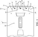
- an embodiment of an electronic ceiling module 64 of vehicle cabin is shown.
- This module is generally intended for lighting the front seats of the vehicle.
- the electronic ceiling module 64 comprises the control panel 10 of the figures 1 and 2
- the three control keys 20, 21, 22 provide the lighting functions of the passenger compartment.
- the electronic ceiling module 64 also comprises a zone equipped with illumination of the passenger compartment 66 of the vehicle.
- the control panel 10 comprises the three control keys 20, 21, 22 arranged in a row according to the invention.
- the three control keys 20, 21, 22 consist of a central control key 20 comprising on both sides of its lateral edges a first lateral key 21 on the one hand and a second lateral key 22 on the other hand .
- the free ends 38, 42, 43 of the three control keys 20, 21, 22 are no coupled to the facade element 12 through the rectilinear opening in the transverse direction of the facade element 12.
- This rectilinear opening extends longitudinally on either side of the control key row 20, 21, 22 , delimiting the transverse edges 31, 34 of the first lateral key 21 and the second lateral key 22 not adjacent to the central key 20.
- the lateral edges 28, 30 of the central control key 20 are, according to the desired embodiment, each separated by a longitudinal opening from the other lateral edges 29, 32 of the first and second lateral control keys 21, 22 thus forming three control keys 20, 21, 22 independent of each other, each separated by a longitudinal groove from the other lateral edges 29, 32 of the first and second lateral keys 21, 22 thus forming a set of three control keys 20, 21, 22, the depression of one of the control keys 20 causes the depression of the other two 21, 22.
- the use of capacitive detection elements 52 under each bearing zone 23 of each control key 20, 21, 22 and the use of a single force sensor 50 arranged in abutment against a second protrusion 46 of one of the three keys 20, 21, 22 is conceivable.
Abstract
Un panneau de commande (10) pour véhicule automobile comprend un support (18); une carte à circuit imprimé (14) qui est fixée sur le support (18); un élément de façade (12) qui est monté sur le support (18) et qui recouvre la carte à circuit imprimé (14); l'élément de façade (12) comprenant au moins une touche de commande (20) actionnable qui est venue de matière avec une partie fixe de l'élément de façade (12) et qui s'étend au-dessus d'une zone de la carte à circuit imprimé (14) ; la touche de commande (20) comportant une extrémité de jonction (36) avec la partie fixe de l'élément de façade (12) et une extrémité libre (38) mobile ; la touche de commande (20) comporte à son extrémité de jonction (36) une première protubérance (44) en appui contre le support (18) et/ou contre la carte à circuit imprimé (14), et comporte à son extrémité libre (38) une zone d'appui (23) prévue pour être touchée par un opérateur en vue d'actionner la touche de commande (20); la touche de commande (20) comporte également une seconde protubérance (46) agencée entre la première protubérance (44) et la zone d'appui (23), ladite seconde protubérance (46) étant de hauteur inférieure à la première protubérance (44) et comportant à son extrémité libre en vis-à-vis de la carte à circuit imprimé (14) une surface d'appui (54) prévue pour venir en contact avec un capteur (50) agencé en vis-à-vis sur la carte à circuit imprimé (14) lorsque la touche de commande (20) est actionnée.

Description
La présente invention concerne un panneau de commande pour véhicule automobile et plus particulièrement les touches de commande d'un tel panneau.The present invention relates to a control panel for a motor vehicle and more particularly the control keys of such a panel.
Les occupants d'une automobile sont très sensibles à l'aspect visuel et au toucher des touches de commande d'un panneau de commande.Occupants of an automobile are very sensitive to the visual appearance and feel of control buttons on a control panel.
Généralement une touche de commande comprend un capuchon fixé dans des éléments de guidage qui peuvent se déplacer le long d'éléments de guidage dans un boîtier. La surface extérieure de ce capuchon est généralement peinte et le symbole graphique est gravé au laser. Un élément de guidage est fabriqué en plastique en tant que partie séparée et le capuchon lui est monté à l'aide de caractéristiques d'écrêtage. L'assemblage est guidé dans le boîtier grâce à des paliers à glissement ou à rotation. Pour améliorer les retours tactiles et réduire le risque de touche de commande bloquée, de la graisse est souvent distribuée sur les surfaces de glissement afin de réduire les frottements glissants. Lorsqu'elle est poussée par un utilisateur, la touche de commande fournit une entrée dans le sens d'activation à un micro-interrupteur pour créer l'état repos / activé.Generally a control key includes a cap secured in guide members that can move along guide members in a housing. The outer surface of this cap is usually painted and the graphic symbol is laser etched. A guide member is made of plastic as a separate part and the cap is mounted to it by means of clipping features. The assembly is guided in the housing by sliding or rotating bearings. To improve tactile feedback and reduce the risk of a blocked control button, grease is often distributed over the sliding surfaces to reduce sliding friction. When pushed by a user, the control key provides an input in the direction of activation to a microswitch to create the idle / on state.
Les panneaux de commande équipés de telles touches de commande sont généralement encombrants et complexes à fabriquer.Control panels equipped with such control keys are generally bulky and complex to manufacture.
Il est donc important de proposer une solution nouvelle résolvant ces problèmes.It is therefore important to propose a new solution solving these problems.
Un panneau de commande pour véhicule automobile comprend un support, une carte à circuit imprimé qui est fixée sur le support, un élément de façade qui est monté sur le support et qui recouvre la carte à circuit imprimé; l'élément de façade comprenant au moins une touche de commande actionnable qui est venue de matière avec une partie fixe de l'élément de façade et qui s'étend au-dessus d'une zone de la carte à circuit imprimé; la touche de commande comportant une extrémité de jonction avec la partie fixe de l'élément de façade et une extrémité libre mobile. La touche de commande comporte à son extrémité de jonction une première protubérance en appui contre le support et/ou contre la carte à circuit imprimé, et comporte à son extrémité libre une zone d'appui prévue pour être touchée par un opérateur en vue d'actionner la touche de commande ; la touche de commande comporte également une seconde protubérance agencée entre la première protubérance et la zone d'appui, ladite seconde protubérance étant de hauteur inférieure à la première protubérance et comportant à son extrémité libre en vis-à-vis de la carte à circuit imprimé une surface d'appui prévue pour venir en contact avec un capteur agencé en vis-à-vis sur la carte à circuit imprimé lorsque la touche de commande est actionnée.A control panel for a motor vehicle comprises a support, a printed circuit board which is fixed on the support, a front element which is mounted on the support and which covers the printed circuit board; the facade element comprising at least one operable control key which is integral with a fixed part of the facade element and which extends above an area of the printed circuit board; the control key having a junction end with the fixed part of the facade element and a mobile free end. The control key comprises at its junction end a first protrusion bearing against the support and / or against the printed circuit board, and has at its free end a bearing zone intended to be touched by an operator for the purpose of activate the control key; the control key also comprises a second protrusion arranged between the first protuberance and the bearing zone, said second protuberance being of height less than the first protuberance and having at its free end opposite the printed circuit board a bearing surface provided to come into contact with a sensor arranged vis-à-vis the printed circuit board when the control key is actuated.
La réalisation de touches de commande venues de matière dans le panneau de commande et d'une structure de touches de commande comparable à un bras de levier est une solution simple et efficace pour permettre la fabrication d'un panneau de commande de faible épaisseur.The provision of control keys integrally formed in the control panel and a control key structure comparable to a lever arm is a simple and effective solution to enable the manufacture of a thin control panel.
La carte à circuit imprimé peut comporter une découpe formant une languette élastique sur laquelle est agencé le capteur. Le support peut comporter un bossage agencé en appui contre la carte à circuit imprimé et agencé sous le capteur. La touche de commande peut comprendre une zone d'épaisseur réduite entre la première protubérance et la seconde protubérance de sorte à faciliter la flexion de la zone d'appui lorsque la touche de commande est actionnée. La zone d'épaisseur réduite peut comprendre un profil d'épaisseur décroissante depuis la seconde protubérance vers la première protubérance.The printed circuit board may comprise a cutout forming an elastic tongue on which the sensor is arranged. The support may comprise a boss arranged in abutment against the printed circuit board and arranged under the sensor. The control key may comprise a zone of reduced thickness between the first protrusion and the second protuberance so as to facilitate the bending of the support zone when the control key is actuated. The area of reduced thickness may include a decreasing thickness profile from the second protuberance to the first protuberance.
Une source de lumière peut être agencée sur la carte à circuit imprimé en vis-à-vis de la zone d'appui et une cavité formant guide de lumière peut être agencée dans l'épaisseur de la touche de commande sous la zone d'appui de sorte à pouvoir éclairer un pictogramme agencé sur la zone d'appui.A light source may be arranged on the printed circuit board opposite the support area and a light guide cavity may be arranged in the thickness of the control key under the support zone. so as to illuminate a pictogram arranged on the support zone.
La touche de commande peut comprendre une troisième protubérance agencée sous l'extrémité libre de la touche de commande et ayant son extrémité libre distante de la carte à circuit imprimé de sorte à former une butée d'arrêt contre la carte à circuit imprimé lorsque la touche de commande est actionnée.The control key may comprise a third protrusion arranged under the free end of the control key and having its free end remote from the printed circuit board so as to form a stop against the printed circuit board when the key command is activated.
Un élément de détection capacitive élastique peut être agencé intercalé entre la zone d'appui de la touche de commande et la carte à circuit imprimé, l'élément de détection capacitive élastique étant agencé au contact de la touche de commande et raccordé électriquement à la carte à circuit imprimé de sorte à détecter un effleurement de la touche de commande par un opérateur. Le capteur peut être un capteur de force agencé au contact de la surface d'appui de la seconde protubérance. Le capteur de force peut être à la fois un capteur tactile et un actionneur haptique.A resilient capacitive sensing element can be arranged interposed between the contact zone of the control key and the printed circuit board, the elastic capacitive sensing element being arranged in contact with the control and electrically connected to the printed circuit board so as to detect a touch of the control key by an operator. The sensor may be a force sensor arranged in contact with the bearing surface of the second protrusion. The force sensor can be both a touch sensor and a haptic actuator.
L'élément de façade peut comprendre une pluralité de touches de commande alignées bord à bord consécutivement l'une après l'autre de sorte que leurs extrémités de jonction sont alignées de manière rectiligne entre elles et que leurs extrémités libres sont alignées de manière rectiligne entre elles ; et deux touches de commande consécutives peuvent être séparées par un évidement de l'élément de façade s'étendant depuis leurs extrémités libres jusque leurs extrémités de jonctions.The facade element may comprise a plurality of control keys aligned edge to edge consecutively one after the other so that their joining ends are aligned rectilinearly with each other and that their free ends are aligned rectilinearly between they; and two consecutive control keys may be separated by a recess of the facade element extending from their free ends to their junction ends.
L'élément de façade peut comprendre une pluralité de touches de commande alignées bord à bord consécutivement l'une après l'autre de sorte que leurs extrémités de jonction sont alignées de manière rectiligne entre elles et que leurs extrémités libres sont alignées de manière rectiligne entre elles ; et deux touches de commande consécutives peuvent être séparées par une rainure de l'élément de façade s'étendant depuis leurs extrémités libres jusque leurs extrémités de jonctions.The facade element may comprise a plurality of control keys aligned edge to edge consecutively one after the other so that their joining ends are aligned rectilinearly with each other and that their free ends are aligned rectilinearly between they; and two consecutive control keys may be separated by a groove of the facade element extending from their free ends to their junction ends.
Un module électronique de plafond d'habitacle de véhicule automobile peut comprendre le panneau de commande décrit ci-dessus.An automotive vehicle interior ceiling module may include the control panel described above.
D'autres buts et avantages de la présente invention apparaîtront au vu de la description qui suit.Other objects and advantages of the present invention will become apparent from the following description.
D'autres caractéristiques, buts et avantages de l'invention apparaîtront à la lecture de la description détaillée qui va suivre, et en regard des dessins annexés, donnés à titre d'exemple non limitatif et sur lesquels:
- La
figure 1 est une vue schématique partielle en perspective et en coupe transversale d'un panneau de commande selon l'invention dont deux touches de commande ont été représentées. - La
figure 2 est une vue schématique éclatée en perspective de lafigure 1 . - La
figure 3 est une vue schématique d'un module électronique de plafond de véhicule comprenant le panneau de commande de lafigure 1 équipé de trois touches de commande.
- The
figure 1 is a partial schematic view in perspective and in cross section of a control panel according to the invention of which two control keys have been represented. - The
figure 2 is an exploded schematic perspective view of thefigure 1 . - The
figure 3 is a schematic view of an electronic vehicle ceiling module including the control panel of thefigure 1 equipped with three control keys.
Afin de faciliter la description, et de façon non limitative, un repère orthogonal comprenant un axe longitudinal L, un axe transversal T et un axe vertical V est défini. Des orientations « bas », « haut », « dessus », « dessous », « inférieure » et « supérieure » sont définies selon la direction verticale. Des orientations « gauche », « droite » et « latérale » sont définies selon la direction transversale. Des orientations « avant » et « arrière » sont également définies selon la direction longitudinale.In order to facilitate the description, and in a nonlimiting manner, an orthogonal reference frame comprising a longitudinal axis L, a transverse axis T and a vertical axis V is defined. "Low", "High", "Above", "Below", "Lower" and "Higher" orientations are defined in the vertical direction. "Left", "right" and "lateral" orientations are defined in the transverse direction. "Forward" and "backward" orientations are also defined along the longitudinal direction.
Selon la
Les touches de commande 20, 22 du panneau de commande 10 représenté sont des touches de commande 20, 22 actionnables qui sont venues de matière avec une partie fixe de l'élément de façade 12. Chaque touche de commande 20, 22 comprend une zone d'appui 23 matérialisée par la présence d'un pictogramme 24, 26. Les deux touches de commande 20, 22 représentées sont agencées en rangée, c'est-à-dire disposées consécutivement l'une à côté de l'autre selon la direction transversale. Chaque touche de commande 20, 22 est globalement de forme rectangulaire. Chaque touche de commande 20, 22 est délimitée par ses deux bords latéraux 28, 30, 32, 34 et par ses deux bords longitudinaux.The
Selon l'invention, les bords latéraux 28, 30, 32, 34 de chaque touche de commande 20, 22 sont délimités par un évidement de matière de l'élément de façade 12. En d'autres termes, les deux touches de commande 20, 22 sont séparées l'une de l'autre par une ouverture longitudinale délimitant leurs bords latéraux adjacents 30, 32. L'autre bord latéral 28, 34 de chaque touche de commande 20, 22 est également délimité par un autre évidement de matière de l'élément de façade 12 formant chacun une autre ouverture longitudinale.According to the invention, the
Un des bords longitudinal de chaque touche de commande 20, 22 est en continuité de matière avec l'élément de façade 12. Le bord longitudinal de chaque touche de commande 20, 22 en continuité de matière avec l'élément de façade 12 défini une extrémité de jonction 36, 40 entre la touche de commande 20, 22 et l'élément de façade 12. Les extrémités de jonctions 36, 40 des deux touches de commande 20, 22 sont identifiées sur la
Selon la
Le pictogramme 24, 26 de chaque touche de commande 20, 22 est agencé suffisamment proche de l'extrémité libre 38, 42 de chaque touche de commande 20, 22 de sorte que la zone d'appui 23 définie par le pictogramme 24, 26 est une zone limitrophe à l'extrémité libre 38, 42 de chaque touche de commande 20, 22. De par les évidements de matière de l'élément de façade 12 autour de chaque touche de commande 20, 22, un appui sur la zone d'appui 23 d'une touche de commande 20, 22 peut permettre un enfoncement de la touche de commande 20, 22 déclenchant l'activation d'une fonction du véhicule.The
De façon alternative, l'ouverture longitudinale délimitant les bords latéraux adjacents 30, 32 des deux touches de commande 20, 22 peut être remplacée par une simple rainure longitudinale réalisée par une réduction d'épaisseur de l'élément de façade 12 entre leurs bords latéraux adjacents 30, 32. En d'autre terme, deux touches de commande 20, 22 adjacentes sont reliées entre elles par la rainure. Dans ce cas, l'application d'une force sur la zone d'appui 23 d'une des deux touches de commande 20, 22 entraine également un enfoncement de l'autre touche de commande 20, 22.Alternatively, the longitudinal opening delimiting the
L'épaisseur, selon l'axe vertical, de chaque touche de commande 20, 22 n'est pas constante. Chaque touche de commande 20, 22 comporte à son extrémité de jonction 36, 40 une première protubérance 44 en appui contre le support 18 et contre la carte à circuit imprimé 14, 16 agencée sous la touche de commande 20, 22. Chaque touche de commande 20, 22 comporte également une seconde protubérance 46 agencée entre la première protubérance 44 et la zone d'appui 23. Chaque touche de commande 20, 22 comprend de plus une troisième protubérance 48 agencée sous l'extrémité libre de la touche de commande 20, 22 formant une butée d'arrêt contre la carte à circuit imprimé 14, 16 lorsque la touche de commande 20, 22 est actionnée.The thickness, along the vertical axis, of each
La première protubérance 44 s'étend transversalement tout le long de l'extrémité de jonction 36, 40 de la touche de commande 20, 22. La première protubérance 44 permet à la touche de commande 20, 22 d'agir comme un levier. La première protubérance 44 sert de point d'appui du levier formé par la touche de commande 20, 22. La section de la touche de commande 20, 22 comprise entre la première protubérance 44 et l'extrémité libre 38, 40 de la touche de commande 20, 22 forme un bras de levier.The
Selon le mode de réalisation représenté, la première protubérance 44 permet également de maintenir la carte à circuit imprimé 14, 16 contre le support 18. De façon alternative, la première protubérance 44 peut ne venir en appui que contre le support 18, la carte à circuit imprimé 14, 16 étant maintenue sur le support 18 par d'autres moyens tels que par exemple par des pions de maintien venus de matière avec le support et permettant le maintien de la carte à circuit imprimé 14, 16.According to the embodiment shown, the
La seconde protubérance 46 comporte à son extrémité libre en vis-à-vis de la carte à circuit imprimé 14, 16 une surface d'appui 54 en contact avec un capteur de force 50 agencé en vis-à-vis sur la carte à circuit imprimé 14, 16. Lorsque la touche de commande 20, 22 n'est pas sollicitée, c'est-à-dire lorsque la touche de commande 20, 22 est dans un état de repos, le capteur de force 50 n'est soumis à aucune sollicitation autre que l'appui naturel de la touche de commande 20, 22. Lorsque la touche de commande 20, 22 est sollicitée par un opérateur exerçant une force d'enfoncement de la zone d'appui 23, c'est-à-dire lorsque la touche de commande 20, 22 est dans un état actionné, le capteur de force 50 est sollicité et peut transmettre une information de force d'appui à une unité de traitement (non représentée).The
Afin d'accentuer la sollicitation du capteur de force 50, la première protubérance 44, c'est-à-dire le point d'appui de la touche de commande 20, 22, peut n'être en appui que contre la carte à circuit imprimé 14, 16.In order to accentuate the biasing of the
La troisième protubérance 48 s'étend transversalement tout le long de l'extrémité libre 38, 42 de la touche de commande 20, 22. La troisième protubérance 48 comprend une extrémité libre 49 distante de la carte à circuit imprimé 14, 16. La distance entre l'extrémité libre 49 de la troisième protubérance 48 de la touche de commande 20, 22 définie la profondeur d'appui possible de la touche de commande 20, 22. En d'autre terme, la hauteur, selon l'axe vertical, de la troisième protubérance 48 peut être ajustée de sorte à obtenir le débattement voulue de la touche de commande 20, 22.The
Les trois protubérances 44, 46, 48 sont venues de matières avec la touche de commande 20, 22.The three
La touche de commande 20, 22 comprend une zone d'épaisseur réduite 51 entre la première protubérance 44 et la seconde protubérance 46 de sorte à faciliter la flexion de la zone d'appui 23 lorsque la touche de commande 20, 22 est actionnée. Plus particulièrement, selon le mode de réalisation représenté, la zone d'épaisseur réduite 51 comprend un profil d'épaisseur décroissante depuis la seconde protubérance 46 vers la première protubérance 44. En d'autres termes, l'épaisseur la plus faible de la touche de commande 20, 22 est localisée au plus proche de la première protubérance 44 permettant ainsi de localiser la flexion de la touche de commande 20, 22 lors de son activation au point d'appui. Egalement, ce profil permet de renforcer la rigidité de la seconde protubérance 46 de la touche de commande 20, 22 afin de pouvoir exercer de façon la plus uniforme possible une force d'appui sur le capteur de force 50 lors de l'activation de la touche de commande 20, 22.The
Selon la
Selon la
D'autres capteurs de force 50 peuvent être envisagés. Des capteurs n'étant pas en un appui permanant contre la seconde protubérance 46 et donc limitant le capteur à un rôle de déclenchement de fonction du véhicule mais ne permettant pas un acquittement par retour de force sont envisageables. Dans ce cas, de simple capteurs de contact sont également envisageables.
Selon le mode réalisation représenté, chaque carte à circuit imprimé 14, 16 comprend une découpe formant une languette 56 élastique sur laquelle est agencé chaque capteur de force 50. L'élasticité de la languette 56 permet de limiter la pression exercée par un opérateur sur le capteur de force 50 de sorte de le protéger contre une force de pression trop importante détériorant le capteur de force 50. L'élasticité de la languette 56 permet également, selon le positionnement du capteur de force 50 sur la languette 56, d'ajuster la sensibilité de détection du capteur de force 50. Il est à noter que la seconde protubérance 46 s'étend seulement au-dessus de la languette 56 et non pas au-dessus de la partie de la carte à circuit imprimé 14, 16 hors languette de manière à ne pas venir en butée sur la partie de la carte à circuit imprimé 14, 16 hors languette lors de l'activation de la touche de commande 20, 22 par un opérateur.According to the embodiment shown, each
Avantageusement, en plus du capteur de force 50, chaque carte à circuit imprimé 14, 16 est équipée d'un élément de détection capacitive 52 agencé sous la zone d'appui 23 de chaque touche de commande 20, 22. L'élément de détection capacitive 52 est de type élastique déformable. Selon le mode de réalisation, l'élément de détection capacitive 52 est de forme annulaire s'étendant globalement sous la zone d'appui 23. Il est bien sur possible d'agencer un élément de détection capacitive de forme différente, l'important est de pouvoir couvrir au mieux la zone d'appui 23. Il peut s'agir d'un élastomère chargé de particules métalliques. L'élément de détection capacitive 52 est agencé au contact de la zone d'appui 23 de la touche de commande 20, 22 et est relié électriquement à la carte à circuit imprimé 14, 16. L'élément de détection capacitive 52 peut permettre une présélection d'une fonction associée à la touche de commande 20, 22 lors d'un effleurement de la touche de commande 20, 22 par un opérateur.Advantageously, in addition to the
L'agencement d'un élément de détection capacitive 52 sous chaque touche de commande 20, 22 peut s'avérer également particulièrement utile lorsque les touches de commandes 20, 22 sont agencées alignées en rangée et que leurs bords latéraux adjacents 30, 32 sont délimités par une rainure. Selon ce mode de réalisation les touches de commande 20, 22 d'une même rangée s'enfoncent toutes ensembles lors d'un appui sur une des touches de commande 20, 22. Dans ce cas de figure, il est possible d'agencer un seul capteur de force 50 sous la surface d'appui 54 d'une seule seconde protubérance 46 d'une seule touche de commande 20. L'unique capteur de force 50 détecte un appui sur l'une quelconque des touches de commande 20, 22 de la rangée de touche de commande 20, 22. L'action sur le capteur de force 50 permet de déclencher une fonction du véhicule associée à la zone d'appui 23 activée et détectée par l'élément de détection capacitive 52.The arrangement of a
Egalement, avantageusement, chaque carte à circuit imprimé 14, 16 comporte une source de lumière 58 prévue pour éclairer le pictogramme 24, 26 de chaque touche de commande 20, 22. Selon le mode réalisation représenté, la source de lumière 58 est agencé en vis-à-vis du pictogramme 24, 26 à éclairer. La source de lumière 58 est donc entourée par l'élément de détection capacitive 52. Afin de concentrer le faisceau lumineux de la source de lumière 58, une cavité 60 formant un guide de lumière est agencée dans l'épaisseur ε de la touche de commande 20, 22 sous la zone d'appui 23.Also, advantageously, each printed
Selon la
Globalement, un effet technique recherché par un tel assemblage est l'obtention d'un panneau de commande 10 de très faible épaisseur. L'utilisation de matière plastique souple et également de cartes à circuit imprimé 14, 16 flexibles permet une utilisation d'un tel panneau de commande 10 dans de nombreux modules électroniques de commandes de l'habitacle d'un véhicule. On notera plus particulièrement l'utilisation d'un tel panneau de commande 10 pour des modules électroniques de plafond de véhicule généralement destiné à l'éclairage de l'habitacle du véhicule ou encore à l'utilisation d'un tel panneau de commande 10 pour les modules frontaux de commande électronique de véhicule telle que les commandes du dispositif multimédia ou encore de climatisation du véhicule.Overall, a technical effect sought by such an assembly is to obtain a
Selon la
Les bords latéraux 28, 30 de la touche de commande centrale 20, sont, selon le mode de réalisation désiré, soit chacun séparés par une ouverture longitudinale des autres bords latéraux 29, 32 de la première et de la seconde touche de commande latérale 21, 22 formant ainsi trois touches de commande 20, 21, 22 indépendante l'une de l'autre, soit chacun séparé par une rainure longitudinale des autres bords latéraux 29, 32 de la première et de la seconde touche latérale 21, 22 formant ainsi un ensemble de trois touches de commande 20, 21, 22 dont l'enfoncement d'une des touches de commande 20 entraine l'enfoncement des deux autres 21, 22. Dans ce dernier cas, l'utilisation d'éléments de détection capacitive 52 sous chaque zone d'appui 23 de chaque touche de commande 20, 21, 22 et l'utilisation d'un seul capteur de force 50 agencé en appui contre une seconde protubérance 46 d'une des trois touches 20, 21, 22 est envisageable.The lateral edges 28, 30 of the
Claims (13)
un support (18);
une carte à circuit imprimé (14) qui est fixée sur le support (18);
un élément de façade (12) qui est monté sur le support (18) et qui recouvre la carte à circuit imprimé (14); l'élément de façade (12) comprenant au moins une touche de commande (20) actionnable qui est venue de matière avec une partie fixe de l'élément de façade (12) et qui s'étend au-dessus d'une zone de la carte à circuit imprimé (14) ; la touche de commande (20) comportant une extrémité de jonction (36) avec la partie fixe de l'élément de façade (12) et une extrémité libre (38) mobile ;
caractérisé en ce que
la touche de commande (20) comporte à son extrémité de jonction (36) une première protubérance (44) en appui contre le support (18) et/ou contre la carte à circuit imprimé (14), et comporte à son extrémité libre (38) une zone d'appui (23) prévue pour être touchée par un opérateur en vue d'actionner la touche de commande (20);
et en ce que la touche de commande (20) comporte également une seconde protubérance (46) agencée entre la première protubérance (44) et la zone d'appui (23), ladite seconde protubérance (46) étant de hauteur inférieure à la première protubérance (44) et comportant à son extrémité libre en vis-à-vis de la carte à circuit imprimé (14) une surface d'appui (54) prévue pour venir en contact avec un capteur (50) agencé en vis-à-vis sur la carte à circuit imprimé (14) lorsque la touche de commande (20) est actionnée.Control panel (10) for a motor vehicle comprising
a support (18);
a printed circuit board (14) which is fixed on the support (18);
a facade element (12) which is mounted on the support (18) and which covers the printed circuit board (14); the facade element (12) comprising at least one actuatable control key (20) which is integrally formed with a fixed part of the facade element (12) and which extends over a zone of the printed circuit board (14); the control key (20) having a junction end (36) with the fixed part of the facade element (12) and a movable free end (38);
characterized in that
the control key (20) comprises at its junction end (36) a first protrusion (44) bearing against the support (18) and / or against the printed circuit board (14), and comprises at its free end ( 38) a bearing zone (23) intended to be touched by an operator to actuate the control key (20);
and in that the control key (20) also comprises a second protrusion (46) arranged between the first protuberance (44) and the bearing zone (23), said second protuberance (46) being of height less than the first protrusion (44) and having at its free end opposite the printed circuit board (14) a bearing surface (54) designed to come into contact with a sensor (50) arranged screw on the printed circuit board (14) when the control key (20) is actuated.
Applications Claiming Priority (1)
| Application Number | Priority Date | Filing Date | Title |
|---|---|---|---|
| FR1754424A FR3066451B1 (en) | 2017-05-18 | 2017-05-18 | CONTROL PANEL FOR MOTOR VEHICLE |
Publications (2)
| Publication Number | Publication Date |
|---|---|
| EP3404506A1 true EP3404506A1 (en) | 2018-11-21 |
| EP3404506B1 EP3404506B1 (en) | 2020-03-18 |
Family
ID=59649858
Family Applications (1)
| Application Number | Title | Priority Date | Filing Date |
|---|---|---|---|
| EP18169727.7A Active EP3404506B1 (en) | 2017-05-18 | 2018-04-27 | Control panel for a motor vehicle |
Country Status (4)
| Country | Link |
|---|---|
| US (1) | US11104278B2 (en) |
| EP (1) | EP3404506B1 (en) |
| CN (1) | CN108944661B (en) |
| FR (1) | FR3066451B1 (en) |
Families Citing this family (6)
| Publication number | Priority date | Publication date | Assignee | Title |
|---|---|---|---|---|
| DE112018003952T5 (en) * | 2017-08-03 | 2020-05-07 | Kabushiki Kaisha Tokai-Rika-Denki-Seisakusho | ACTUATION DETECTING DEVICE |
| US10586943B2 (en) * | 2017-12-22 | 2020-03-10 | Sakai Display Products Corporation | Display apparatus and method for attaching display panel |
| CN110677148A (en) | 2019-09-19 | 2020-01-10 | 浙江捷昌线性驱动科技股份有限公司 | Operator for controlling electric adjustable furniture |
| CN112540692B (en) * | 2019-09-20 | 2023-06-27 | 法雷奥汽车内部控制(深圳)有限公司 | Touch control operation device |
| FR3101288B1 (en) * | 2019-09-27 | 2021-10-29 | Valeo Systemes Thermiques | Electronic interface box of an electric heating device of a ventilation, heating and / or air conditioning installation of a motor vehicle |
| DE102020112249B4 (en) | 2020-05-06 | 2024-04-25 | Preh Gmbh | Control element with solid-state joint |
Citations (3)
| Publication number | Priority date | Publication date | Assignee | Title |
|---|---|---|---|---|
| US20090173613A1 (en) * | 2005-03-02 | 2009-07-09 | Huf Hulsbeck & Furst Gmbh & Co. Kg | Electronic Key |
| US20100314229A1 (en) * | 2009-06-10 | 2010-12-16 | Brother Kogyo Kabushiki Kaisha | Push button switch device and sewing machine provided therewith |
| WO2013168721A1 (en) * | 2012-05-09 | 2013-11-14 | Yazaki Corporation | Display switch |
Family Cites Families (10)
| Publication number | Priority date | Publication date | Assignee | Title |
|---|---|---|---|---|
| US5521342A (en) * | 1994-12-27 | 1996-05-28 | General Motors Corporation | Switch having combined light pipe and printed circuit board |
| DE19964166C1 (en) * | 1999-12-10 | 2001-08-16 | Huf Huelsbeck & Fuerst Gmbh | Housing for electronic key |
| US8432678B2 (en) * | 2010-01-06 | 2013-04-30 | Apple Inc. | Component assembly |
| FR2976867B1 (en) | 2011-06-23 | 2013-11-08 | Delphi Tech Inc | CONTROL PANEL COMPRISING A RESISTIVE TYPE RETRO-LIKE BUTTON |
| DE102015109549A1 (en) | 2014-06-25 | 2015-12-31 | Ford Global Technologies, Llc | Proximity switch assembly with a groove between adjacent proximity sensors |
| KR101565047B1 (en) | 2014-08-12 | 2015-11-02 | 현대자동차주식회사 | Control board having steering wheel and accelerator pedal integrated structure |
| US9720500B2 (en) | 2014-11-07 | 2017-08-01 | Faurecia Interior Systems, Inc | Haptic touch panel assembly for a vehicle |
| CN204204708U (en) | 2014-11-28 | 2015-03-11 | 袁建平 | Magnetic key and keyboard thereof |
| CN205428785U (en) | 2015-08-31 | 2016-08-03 | 东莞市长资实业有限公司 | Lever -type input device micro -gap switch button |
| CN205194585U (en) | 2015-12-18 | 2016-04-27 | 南京创维家用电器有限公司 | Domestic appliance button structure and washing machine |
-
2017
- 2017-05-18 FR FR1754424A patent/FR3066451B1/en active Active
-
2018
- 2018-04-27 EP EP18169727.7A patent/EP3404506B1/en active Active
- 2018-05-04 US US15/970,950 patent/US11104278B2/en active Active
- 2018-05-14 CN CN201810454443.6A patent/CN108944661B/en active Active
Patent Citations (3)
| Publication number | Priority date | Publication date | Assignee | Title |
|---|---|---|---|---|
| US20090173613A1 (en) * | 2005-03-02 | 2009-07-09 | Huf Hulsbeck & Furst Gmbh & Co. Kg | Electronic Key |
| US20100314229A1 (en) * | 2009-06-10 | 2010-12-16 | Brother Kogyo Kabushiki Kaisha | Push button switch device and sewing machine provided therewith |
| WO2013168721A1 (en) * | 2012-05-09 | 2013-11-14 | Yazaki Corporation | Display switch |
Also Published As
| Publication number | Publication date |
|---|---|
| US11104278B2 (en) | 2021-08-31 |
| US20180334107A1 (en) | 2018-11-22 |
| FR3066451A1 (en) | 2018-11-23 |
| CN108944661A (en) | 2018-12-07 |
| CN108944661B (en) | 2021-06-08 |
| EP3404506B1 (en) | 2020-03-18 |
| FR3066451B1 (en) | 2019-05-03 |
Similar Documents
| Publication | Publication Date | Title |
|---|---|---|
| EP3404506B1 (en) | Control panel for a motor vehicle | |
| EP2109869B1 (en) | Electric control device | |
| EP2165250B1 (en) | Electric control device | |
| EP2054904B1 (en) | Control module, in particular for an automotive vehicle module | |
| FR2976867A1 (en) | CONTROL PANEL COMPRISING A RESISTIVE TYPE RETRO-LIKE BUTTON | |
| EP3404682B1 (en) | Operation assembly by sliding contact of a control panel for a motor vehicle | |
| EP2151054B1 (en) | Haptic feedback tactile control device | |
| EP2130113A1 (en) | Electric control device for an automobile | |
| EP2342728B1 (en) | Keypad with long key travel and improved touch feeling | |
| EP2244167A2 (en) | Control device with haptic feedback | |
| EP1424710B1 (en) | Control device for at least two functions of an element and/or at least two different parts of an element | |
| FR3070637B1 (en) | OPTICAL TOUCH PALLET ON DRIVET WHEEL FOR FINGER DETECTION | |
| WO2012019944A1 (en) | Control panel with resistive keys and prestressed sensors | |
| FR3016563A1 (en) | TOUCH CONTROL DEVICE FOR MOTOR VEHICLE DASHBOARD | |
| EP2678183B1 (en) | Motor vehicle control device | |
| EP2372738B1 (en) | Control module | |
| EP3241702A1 (en) | Control panel for a motor vehicle | |
| EP2577700B1 (en) | Electrical switch, of the normally-closed type, especially for a portable communication device | |
| EP2685347B1 (en) | Ergonomic frame for tactile command interface and corresponding command interface | |
| FR2939215A1 (en) | RETROECLATIVE WATERPROOF KEYBOARD | |
| WO2019048771A1 (en) | Optical-effect touchpad on a steering wheel for finger detection | |
| FR3026841A1 (en) | CAPACITIVE SENSOR | |
| EP1650778A1 (en) | Electrical control device for vehicle roofliner |
Legal Events
| Date | Code | Title | Description |
|---|---|---|---|
| PUAI | Public reference made under article 153(3) epc to a published international application that has entered the european phase |
Free format text: ORIGINAL CODE: 0009012 |
|
| STAA | Information on the status of an ep patent application or granted ep patent |
Free format text: STATUS: THE APPLICATION HAS BEEN PUBLISHED |
|
| AK | Designated contracting states |
Kind code of ref document: A1 Designated state(s): AL AT BE BG CH CY CZ DE DK EE ES FI FR GB GR HR HU IE IS IT LI LT LU LV MC MK MT NL NO PL PT RO RS SE SI SK SM TR |
|
| AX | Request for extension of the european patent |
Extension state: BA ME |
|
| RAP1 | Party data changed (applicant data changed or rights of an application transferred) |
Owner name: APTIV TECHNOLOGIES LIMITED |
|
| STAA | Information on the status of an ep patent application or granted ep patent |
Free format text: STATUS: REQUEST FOR EXAMINATION WAS MADE |
|
| 17P | Request for examination filed |
Effective date: 20190516 |
|
| RBV | Designated contracting states (corrected) |
Designated state(s): AL AT BE BG CH CY CZ DE DK EE ES FI FR GB GR HR HU IE IS IT LI LT LU LV MC MK MT NL NO PL PT RO RS SE SI SK SM TR |
|
| GRAP | Despatch of communication of intention to grant a patent |
Free format text: ORIGINAL CODE: EPIDOSNIGR1 |
|
| STAA | Information on the status of an ep patent application or granted ep patent |
Free format text: STATUS: GRANT OF PATENT IS INTENDED |
|
| INTG | Intention to grant announced |
Effective date: 20191023 |
|
| GRAS | Grant fee paid |
Free format text: ORIGINAL CODE: EPIDOSNIGR3 |
|
| GRAA | (expected) grant |
Free format text: ORIGINAL CODE: 0009210 |
|
| STAA | Information on the status of an ep patent application or granted ep patent |
Free format text: STATUS: THE PATENT HAS BEEN GRANTED |
|
| AK | Designated contracting states |
Kind code of ref document: B1 Designated state(s): AL AT BE BG CH CY CZ DE DK EE ES FI FR GB GR HR HU IE IS IT LI LT LU LV MC MK MT NL NO PL PT RO RS SE SI SK SM TR |
|
| REG | Reference to a national code |
Ref country code: GB Ref legal event code: FG4D Free format text: NOT ENGLISH |
|
| REG | Reference to a national code |
Ref country code: DE Ref legal event code: R096 Ref document number: 602018003064 Country of ref document: DE |
|
| REG | Reference to a national code |
Ref country code: AT Ref legal event code: REF Ref document number: 1246655 Country of ref document: AT Kind code of ref document: T Effective date: 20200415 Ref country code: IE Ref legal event code: FG4D Free format text: LANGUAGE OF EP DOCUMENT: FRENCH |
|
| PG25 | Lapsed in a contracting state [announced via postgrant information from national office to epo] |
Ref country code: RS Free format text: LAPSE BECAUSE OF FAILURE TO SUBMIT A TRANSLATION OF THE DESCRIPTION OR TO PAY THE FEE WITHIN THE PRESCRIBED TIME-LIMIT Effective date: 20200318 Ref country code: NO Free format text: LAPSE BECAUSE OF FAILURE TO SUBMIT A TRANSLATION OF THE DESCRIPTION OR TO PAY THE FEE WITHIN THE PRESCRIBED TIME-LIMIT Effective date: 20200618 Ref country code: FI Free format text: LAPSE BECAUSE OF FAILURE TO SUBMIT A TRANSLATION OF THE DESCRIPTION OR TO PAY THE FEE WITHIN THE PRESCRIBED TIME-LIMIT Effective date: 20200318 |
|
| REG | Reference to a national code |
Ref country code: NL Ref legal event code: MP Effective date: 20200318 |
|
| PG25 | Lapsed in a contracting state [announced via postgrant information from national office to epo] |
Ref country code: HR Free format text: LAPSE BECAUSE OF FAILURE TO SUBMIT A TRANSLATION OF THE DESCRIPTION OR TO PAY THE FEE WITHIN THE PRESCRIBED TIME-LIMIT Effective date: 20200318 Ref country code: LV Free format text: LAPSE BECAUSE OF FAILURE TO SUBMIT A TRANSLATION OF THE DESCRIPTION OR TO PAY THE FEE WITHIN THE PRESCRIBED TIME-LIMIT Effective date: 20200318 Ref country code: SE Free format text: LAPSE BECAUSE OF FAILURE TO SUBMIT A TRANSLATION OF THE DESCRIPTION OR TO PAY THE FEE WITHIN THE PRESCRIBED TIME-LIMIT Effective date: 20200318 Ref country code: GR Free format text: LAPSE BECAUSE OF FAILURE TO SUBMIT A TRANSLATION OF THE DESCRIPTION OR TO PAY THE FEE WITHIN THE PRESCRIBED TIME-LIMIT Effective date: 20200619 Ref country code: BG Free format text: LAPSE BECAUSE OF FAILURE TO SUBMIT A TRANSLATION OF THE DESCRIPTION OR TO PAY THE FEE WITHIN THE PRESCRIBED TIME-LIMIT Effective date: 20200618 |
|
| REG | Reference to a national code |
Ref country code: LT Ref legal event code: MG4D |
|
| PG25 | Lapsed in a contracting state [announced via postgrant information from national office to epo] |
Ref country code: NL Free format text: LAPSE BECAUSE OF FAILURE TO SUBMIT A TRANSLATION OF THE DESCRIPTION OR TO PAY THE FEE WITHIN THE PRESCRIBED TIME-LIMIT Effective date: 20200318 |
|
| PG25 | Lapsed in a contracting state [announced via postgrant information from national office to epo] |
Ref country code: SM Free format text: LAPSE BECAUSE OF FAILURE TO SUBMIT A TRANSLATION OF THE DESCRIPTION OR TO PAY THE FEE WITHIN THE PRESCRIBED TIME-LIMIT Effective date: 20200318 Ref country code: RO Free format text: LAPSE BECAUSE OF FAILURE TO SUBMIT A TRANSLATION OF THE DESCRIPTION OR TO PAY THE FEE WITHIN THE PRESCRIBED TIME-LIMIT Effective date: 20200318 Ref country code: SK Free format text: LAPSE BECAUSE OF FAILURE TO SUBMIT A TRANSLATION OF THE DESCRIPTION OR TO PAY THE FEE WITHIN THE PRESCRIBED TIME-LIMIT Effective date: 20200318 Ref country code: IS Free format text: LAPSE BECAUSE OF FAILURE TO SUBMIT A TRANSLATION OF THE DESCRIPTION OR TO PAY THE FEE WITHIN THE PRESCRIBED TIME-LIMIT Effective date: 20200718 Ref country code: CZ Free format text: LAPSE BECAUSE OF FAILURE TO SUBMIT A TRANSLATION OF THE DESCRIPTION OR TO PAY THE FEE WITHIN THE PRESCRIBED TIME-LIMIT Effective date: 20200318 Ref country code: LT Free format text: LAPSE BECAUSE OF FAILURE TO SUBMIT A TRANSLATION OF THE DESCRIPTION OR TO PAY THE FEE WITHIN THE PRESCRIBED TIME-LIMIT Effective date: 20200318 Ref country code: PT Free format text: LAPSE BECAUSE OF FAILURE TO SUBMIT A TRANSLATION OF THE DESCRIPTION OR TO PAY THE FEE WITHIN THE PRESCRIBED TIME-LIMIT Effective date: 20200812 Ref country code: EE Free format text: LAPSE BECAUSE OF FAILURE TO SUBMIT A TRANSLATION OF THE DESCRIPTION OR TO PAY THE FEE WITHIN THE PRESCRIBED TIME-LIMIT Effective date: 20200318 |
|
| REG | Reference to a national code |
Ref country code: AT Ref legal event code: MK05 Ref document number: 1246655 Country of ref document: AT Kind code of ref document: T Effective date: 20200318 |
|
| REG | Reference to a national code |
Ref country code: DE Ref legal event code: R097 Ref document number: 602018003064 Country of ref document: DE |
|
| PG25 | Lapsed in a contracting state [announced via postgrant information from national office to epo] |
Ref country code: MC Free format text: LAPSE BECAUSE OF FAILURE TO SUBMIT A TRANSLATION OF THE DESCRIPTION OR TO PAY THE FEE WITHIN THE PRESCRIBED TIME-LIMIT Effective date: 20200318 |
|
| PLBE | No opposition filed within time limit |
Free format text: ORIGINAL CODE: 0009261 |
|
| STAA | Information on the status of an ep patent application or granted ep patent |
Free format text: STATUS: NO OPPOSITION FILED WITHIN TIME LIMIT |
|
| PG25 | Lapsed in a contracting state [announced via postgrant information from national office to epo] |
Ref country code: ES Free format text: LAPSE BECAUSE OF FAILURE TO SUBMIT A TRANSLATION OF THE DESCRIPTION OR TO PAY THE FEE WITHIN THE PRESCRIBED TIME-LIMIT Effective date: 20200318 Ref country code: LU Free format text: LAPSE BECAUSE OF NON-PAYMENT OF DUE FEES Effective date: 20200427 Ref country code: AT Free format text: LAPSE BECAUSE OF FAILURE TO SUBMIT A TRANSLATION OF THE DESCRIPTION OR TO PAY THE FEE WITHIN THE PRESCRIBED TIME-LIMIT Effective date: 20200318 Ref country code: DK Free format text: LAPSE BECAUSE OF FAILURE TO SUBMIT A TRANSLATION OF THE DESCRIPTION OR TO PAY THE FEE WITHIN THE PRESCRIBED TIME-LIMIT Effective date: 20200318 Ref country code: IT Free format text: LAPSE BECAUSE OF FAILURE TO SUBMIT A TRANSLATION OF THE DESCRIPTION OR TO PAY THE FEE WITHIN THE PRESCRIBED TIME-LIMIT Effective date: 20200318 |
|
| REG | Reference to a national code |
Ref country code: BE Ref legal event code: MM Effective date: 20200430 |
|
| 26N | No opposition filed |
Effective date: 20201221 |
|
| PG25 | Lapsed in a contracting state [announced via postgrant information from national office to epo] |
Ref country code: PL Free format text: LAPSE BECAUSE OF FAILURE TO SUBMIT A TRANSLATION OF THE DESCRIPTION OR TO PAY THE FEE WITHIN THE PRESCRIBED TIME-LIMIT Effective date: 20200318 Ref country code: BE Free format text: LAPSE BECAUSE OF NON-PAYMENT OF DUE FEES Effective date: 20200430 |
|
| PG25 | Lapsed in a contracting state [announced via postgrant information from national office to epo] |
Ref country code: IE Free format text: LAPSE BECAUSE OF NON-PAYMENT OF DUE FEES Effective date: 20200427 |
|
| PG25 | Lapsed in a contracting state [announced via postgrant information from national office to epo] |
Ref country code: SI Free format text: LAPSE BECAUSE OF FAILURE TO SUBMIT A TRANSLATION OF THE DESCRIPTION OR TO PAY THE FEE WITHIN THE PRESCRIBED TIME-LIMIT Effective date: 20200318 |
|
| PG25 | Lapsed in a contracting state [announced via postgrant information from national office to epo] |
Ref country code: CH Free format text: LAPSE BECAUSE OF NON-PAYMENT OF DUE FEES Effective date: 20210430 Ref country code: LI Free format text: LAPSE BECAUSE OF NON-PAYMENT OF DUE FEES Effective date: 20210430 |
|
| PG25 | Lapsed in a contracting state [announced via postgrant information from national office to epo] |
Ref country code: TR Free format text: LAPSE BECAUSE OF FAILURE TO SUBMIT A TRANSLATION OF THE DESCRIPTION OR TO PAY THE FEE WITHIN THE PRESCRIBED TIME-LIMIT Effective date: 20200318 Ref country code: MT Free format text: LAPSE BECAUSE OF FAILURE TO SUBMIT A TRANSLATION OF THE DESCRIPTION OR TO PAY THE FEE WITHIN THE PRESCRIBED TIME-LIMIT Effective date: 20200318 Ref country code: CY Free format text: LAPSE BECAUSE OF FAILURE TO SUBMIT A TRANSLATION OF THE DESCRIPTION OR TO PAY THE FEE WITHIN THE PRESCRIBED TIME-LIMIT Effective date: 20200318 |
|
| PG25 | Lapsed in a contracting state [announced via postgrant information from national office to epo] |
Ref country code: MK Free format text: LAPSE BECAUSE OF FAILURE TO SUBMIT A TRANSLATION OF THE DESCRIPTION OR TO PAY THE FEE WITHIN THE PRESCRIBED TIME-LIMIT Effective date: 20200318 Ref country code: AL Free format text: LAPSE BECAUSE OF FAILURE TO SUBMIT A TRANSLATION OF THE DESCRIPTION OR TO PAY THE FEE WITHIN THE PRESCRIBED TIME-LIMIT Effective date: 20200318 |
|
| P01 | Opt-out of the competence of the unified patent court (upc) registered |
Effective date: 20230424 |
|
| PGFP | Annual fee paid to national office [announced via postgrant information from national office to epo] |
Ref country code: FR Payment date: 20230428 Year of fee payment: 6 Ref country code: DE Payment date: 20230426 Year of fee payment: 6 |
|
| PGFP | Annual fee paid to national office [announced via postgrant information from national office to epo] |
Ref country code: GB Payment date: 20230420 Year of fee payment: 6 |