EP3404331A1 - Ensemble mélangeur carburant-air destiné à être utilisé dans une chambre de combustion d'un moteur à turbine - Google Patents
Ensemble mélangeur carburant-air destiné à être utilisé dans une chambre de combustion d'un moteur à turbine Download PDFInfo
- Publication number
- EP3404331A1 EP3404331A1 EP18173047.4A EP18173047A EP3404331A1 EP 3404331 A1 EP3404331 A1 EP 3404331A1 EP 18173047 A EP18173047 A EP 18173047A EP 3404331 A1 EP3404331 A1 EP 3404331A1
- Authority
- EP
- European Patent Office
- Prior art keywords
- fuel
- combustor
- air mixer
- round
- fuel air
- Prior art date
- Legal status (The legal status is an assumption and is not a legal conclusion. Google has not performed a legal analysis and makes no representation as to the accuracy of the status listed.)
- Granted
Links
- 239000000446 fuel Substances 0.000 title claims abstract description 120
- 230000000712 assembly Effects 0.000 claims abstract description 64
- 238000000429 assembly Methods 0.000 claims abstract description 64
- 239000007921 spray Substances 0.000 claims description 25
- 239000000203 mixture Substances 0.000 claims description 19
- 238000002485 combustion reaction Methods 0.000 description 16
- 239000007789 gas Substances 0.000 description 10
- 230000008901 benefit Effects 0.000 description 5
- 238000001816 cooling Methods 0.000 description 4
- PXHVJJICTQNCMI-UHFFFAOYSA-N Nickel Chemical compound [Ni] PXHVJJICTQNCMI-UHFFFAOYSA-N 0.000 description 2
- 230000005540 biological transmission Effects 0.000 description 2
- 239000000567 combustion gas Substances 0.000 description 2
- 239000000463 material Substances 0.000 description 2
- 230000006641 stabilisation Effects 0.000 description 2
- 238000011105 stabilization Methods 0.000 description 2
- 230000003068 static effect Effects 0.000 description 2
- 239000004215 Carbon black (E152) Substances 0.000 description 1
- 239000000654 additive Substances 0.000 description 1
- 230000000996 additive effect Effects 0.000 description 1
- 229910045601 alloy Inorganic materials 0.000 description 1
- 239000000956 alloy Substances 0.000 description 1
- 230000009286 beneficial effect Effects 0.000 description 1
- 239000000919 ceramic Substances 0.000 description 1
- 238000006243 chemical reaction Methods 0.000 description 1
- 238000004891 communication Methods 0.000 description 1
- 230000006835 compression Effects 0.000 description 1
- 238000007906 compression Methods 0.000 description 1
- 230000009977 dual effect Effects 0.000 description 1
- 230000000694 effects Effects 0.000 description 1
- 238000005516 engineering process Methods 0.000 description 1
- 229930195733 hydrocarbon Natural products 0.000 description 1
- 150000002430 hydrocarbons Chemical class 0.000 description 1
- 238000012423 maintenance Methods 0.000 description 1
- 238000004519 manufacturing process Methods 0.000 description 1
- 238000005259 measurement Methods 0.000 description 1
- 238000002844 melting Methods 0.000 description 1
- 230000008018 melting Effects 0.000 description 1
- 239000002184 metal Substances 0.000 description 1
- 229910052751 metal Inorganic materials 0.000 description 1
- 238000002156 mixing Methods 0.000 description 1
- 238000012986 modification Methods 0.000 description 1
- 230000004048 modification Effects 0.000 description 1
- 239000003607 modifier Substances 0.000 description 1
- 229910052759 nickel Inorganic materials 0.000 description 1
- 230000003954 pattern orientation Effects 0.000 description 1
- 230000000737 periodic effect Effects 0.000 description 1
- 230000002028 premature Effects 0.000 description 1
- 230000009467 reduction Effects 0.000 description 1
- 230000004044 response Effects 0.000 description 1
- 230000007480 spreading Effects 0.000 description 1
- 229910000601 superalloy Inorganic materials 0.000 description 1
Images


Classifications
-
- F—MECHANICAL ENGINEERING; LIGHTING; HEATING; WEAPONS; BLASTING
- F23—COMBUSTION APPARATUS; COMBUSTION PROCESSES
- F23R—GENERATING COMBUSTION PRODUCTS OF HIGH PRESSURE OR HIGH VELOCITY, e.g. GAS-TURBINE COMBUSTION CHAMBERS
- F23R3/00—Continuous combustion chambers using liquid or gaseous fuel
- F23R3/28—Continuous combustion chambers using liquid or gaseous fuel characterised by the fuel supply
- F23R3/286—Continuous combustion chambers using liquid or gaseous fuel characterised by the fuel supply having fuel-air premixing devices
-
- F—MECHANICAL ENGINEERING; LIGHTING; HEATING; WEAPONS; BLASTING
- F23—COMBUSTION APPARATUS; COMBUSTION PROCESSES
- F23R—GENERATING COMBUSTION PRODUCTS OF HIGH PRESSURE OR HIGH VELOCITY, e.g. GAS-TURBINE COMBUSTION CHAMBERS
- F23R3/00—Continuous combustion chambers using liquid or gaseous fuel
- F23R3/002—Wall structures
-
- F—MECHANICAL ENGINEERING; LIGHTING; HEATING; WEAPONS; BLASTING
- F23—COMBUSTION APPARATUS; COMBUSTION PROCESSES
- F23R—GENERATING COMBUSTION PRODUCTS OF HIGH PRESSURE OR HIGH VELOCITY, e.g. GAS-TURBINE COMBUSTION CHAMBERS
- F23R3/00—Continuous combustion chambers using liquid or gaseous fuel
- F23R3/02—Continuous combustion chambers using liquid or gaseous fuel characterised by the air-flow or gas-flow configuration
- F23R3/04—Air inlet arrangements
- F23R3/10—Air inlet arrangements for primary air
- F23R3/12—Air inlet arrangements for primary air inducing a vortex
- F23R3/14—Air inlet arrangements for primary air inducing a vortex by using swirl vanes
Definitions
- the present disclosure relates to a gas turbine engine and, more particularly, to a fuel air mixer assembly for a combustor section therefor.
- Gas turbine engines such as those which power modern commercial and military aircraft, include a compressor for pressurizing a supply of air, a combustor for burning a hydrocarbon fuel in the presence of the pressurized air, and a turbine for extracting energy from the resultant combustion gases.
- the combustor generally includes radially spaced apart inner and outer wall assemblies that define an annular combustion chamber therebetween.
- Gas turbine combustors typically utilize a fuel nozzle integrated with air introduction that effectively mixes the fuel spray with air to generate a fine spray for ignition and continuous combustion.
- the fuel air mixer assembly in most modern combustors includes a swirler where one or more air passages interact with one or more fuel passages from a fuel nozzle.
- the fuel air mixer assembly includes slots or holes radially outboard of the fuel nozzle to interact as a system to provide an atomized fuel-air mixture that is conical in shape.
- These axisymmetric conical fuel air mixtures provide flame patterns which form uniform periodic horseshoe shaped impact, or "touchdown regions,” on the combustor wall surfaces which may ultimately form hot spots that may result in premature failure.
- a fuel air mixer assembly includes a non-round swirler arranged along a swirler axis; and a non-round fuel nozzle received at least partially within the non-round swirler.
- An aspect of the present disclosure includes, wherein the non-round fuel nozzle includes a multiple of fuel jets, a first of the multiple of fuel jets of a size different than a second of the multiple of fuel jets.
- a further aspect of the present disclosure includes, wherein the non-round fuel nozzle is arranged along the swirler axis.
- a further aspect of the present disclosure includes, wherein the non-round fuel nozzle is elliptical in cross-section.
- a further aspect of the present disclosure includes, wherein the non-round fuel nozzle is rectilinear in cross-section.
- a combustor for a gas turbine engine includes a multiple of fuel air mixer assemblies defined around an engine central longitudinal axis, each of the multiple of fuel air mixer assemblies including a non-round swirler which at least partially receives a fuel nozzle along a swirler axis of each of the respective multiple of mixer assemblies, each of the multiple of fuel air mixer assemblies operable to provide a non-round fuel air mixture spray pattern that at least partially overlaps an adjacent non-round fuel air mixture spray pattern.
- An aspect of the present disclosure includes, wherein the non-round swirler of each of the respective multiple of fuel air mixer assemblies is elliptical.
- a further aspect of the present disclosure includes, wherein the non-round swirler of each of the respective multiple of fuel air mixer assemblies is arranged such that a major axis thereof is clocked relative to the major axis of an adjacent one of the multiple of mixer assemblies.
- a further aspect of the present disclosure includes, wherein the swirler of each of the respective multiple of fuel air mixer assemblies is arranged such that a major axis thereof is clocked to define a circular distribution around an engine central longitudinal axis.
- a further aspect of the present disclosure includes, wherein the fuel-air mixture pattern from each of the respective multiple of fuel air mixer assemblies at least partially overlaps an adjacent one of the respective multiple of mixer assemblies.
- a combustor for a gas turbine engine includes a multiple of fuel air mixer assemblies defined around an engine central longitudinal axis, each of the multiple of fuel air mixer assemblies including a non-round swirler which at least partially receives a fuel nozzle along the axis of each of the respective multiple of fuel air mixer assemblies operable to provide a non-round fuel air mixture spray pattern, each of the multiple of fuel air mixer assemblies being clocked in relation to the circumferential position within the combustor.
- An aspect of the present disclosure includes, wherein the non-round swirler of each of the respective multiple of fuel air mixer assemblies is arranged such that a major axis thereof is clocked relative to the major axis of an adjacent one of the multiple of mixer assemblies.
- a further aspect of the present disclosure includes, wherein the swirler of each of the respective multiple of fuel air mixer assemblies is arranged such that a major axis thereof is clocked to define a circular distribution around an engine central longitudinal axis.
- a further aspect of the present disclosure includes, wherein the non-round fuel-air mixture pattern from each of the respective multiple of fuel air mixer assemblies at least partially overlaps an adjacent one of the respective multiple of mixer assemblies.
- a further aspect of the present disclosure includes, wherein the swirler of each of the respective multiple of fuel air mixer assemblies is arranged such that a major axis thereof is oriented to be generally parallel with respect to an inner and outer combustor liner assembly.
- a further aspect of the present disclosure includes, wherein the swirler of each of the respective multiple of fuel air mixer assemblies is arranged such that a major axis thereof is clocked with respect to an inner and outer combustor liner assembly.
- a further aspect of the present disclosure includes, wherein the swirler of each of the respective multiple of fuel air mixer assemblies is arranged such that a major axis thereof is clocked to form a circular arrangement around an engine axis.
- a further aspect of the present disclosure includes, wherein the fuel nozzle of each of the respective multiple of fuel air mixer assemblies is arranged such that a major axis thereof is clocked around an engine axis.
- a further aspect of the present disclosure includes, wherein the swirler of at least one of the multiple of fuel air mixer assemblies is arranged such that a major axis thereof is clocked relative to at least one other of the multiple of mixer assemblies.
- a further aspect of the present disclosure includes, wherein the fuel nozzle of at least one of the multiple of fuel air mixer assemblies is arranged such that a major axis thereof is clocked relative to at least one other of the multiple of mixer assemblies.
- Lock refers to the rotational position of the non-round swirler around the swirler axis.
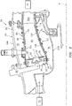
- FIG. 1 schematically illustrates a gas turbine engine 20.
- the gas turbine engine 20 is disclosed herein as a two-spool turbofan that generally incorporates a fan section 22, a compressor section 24, a combustor section 26 and a turbine section 28.
- the fan section 22 drives air along a bypass flowpath while the compressor section 24 drives air along a core flowpath for compression and communication into the combustor section 26 then expansion through the turbine section 28.
- a turbofan in the disclosed non-limiting embodiment, it should be appreciated that the concepts described herein are not limited to use with turbofans as the teachings may be applied to other types of turbine engines such as a turbojets, turboshafts, and three-spool (plus fan) turbofans.
- the engine 20 generally includes a low spool 30 and a high spool 32 mounted for rotation about an engine central longitudinal axis A relative to an engine static structure 36 via several bearing structures 38.
- the low spool 30 generally includes an inner shaft 40 that interconnects a fan 42, a low pressure compressor (“LPC”) 44 and a low pressure turbine (“LPT”) 46.
- the inner shaft 40 drives the fan 42 directly or through a geared architecture 48 to drive the fan 42 at a lower speed than the low spool 30.
- An exemplary reduction transmission is an epicyclic transmission, namely a planetary or star gear system.
- the high spool 32 includes an outer shaft 50 that interconnects a high pressure compressor (“HPC”) 52 and high pressure turbine (“HPT”) 54.
- a combustor 56 is arranged between the high pressure compressor 52 and the high pressure turbine 54.
- the inner shaft 40 and the outer shaft 50 are concentric and rotate about the engine central longitudinal axis A which is collinear with their longitudinal axes.
- Core airflow is compressed by the LPC 44, then the HPC 52, mixed with the fuel and burned in the combustor 56, then expanded over the HPT 54 and the LPT 46.
- the HPT 54 and LPT 46 rotationally drive the respective low spool 30 and high spool 32 in response to the expansion.
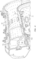
- the combustor section 26 generally includes a combustor 56 with an outer combustor wall assembly 60, an inner combustor wall assembly 62 and a diffuser case module 64.
- the outer combustor wall assembly 60 and the inner combustor wall assembly 62 are spaced apart such that a combustion chamber 66 is defined therebetween.
- the combustion chamber 66 is generally annular in shape.
- the outer combustor wall assembly 60 is spaced radially inward from an outer diffuser case 64A of the diffuser case module 64 to define an outer annular plenum 76.
- the inner combustor wall assembly 62 is spaced radially outward from an inner diffuser case 64B of the diffuser case module 64 to define an inner annular plenum 78. It should be appreciated that although a particular combustor is illustrated, other combustor types with various combustor liner arrangements will also benefit herefrom. It should be further appreciated that the disclosed cooling flow paths are but an illustrated embodiment and should not be limited only thereto.
- the combustor wall assemblies 60, 62 contain the combustion products for direction toward the turbine section 28.
- Each combustor wall assembly 60, 62 generally include a respective support shell 68, 70 which supports one or more liner panels 72, 74 mounted to a hot side of the respective support shell 68, 70.
- the combustor wall assemblies 60, 62 may also be referred to as combustor liner assemblies. Although a dual wall liner assembly is illustrated, a single-wall liner may also benefit herefrom.
- Each of the liner panels 72, 74 may be generally rectilinear and manufactured of, for example, a nickel based super alloy, ceramic or other temperature resistant material and are arranged to form a liner array.
- the liner array includes a multiple of forward liner panels 72A, 72B and the multiple of aft liner panels 74A, 74B.
- the multiple of forward liner panels 72A, 72B and the multiple of aft liner panels 74A, 74B are arranged to line the hot side of the inner shell 70 ( FIG. 3 ).
- the combustor 56 further includes a forward assembly 80 immediately downstream of the compressor section 24 to receive compressed airflow therefrom.
- the forward assembly 80 generally includes an annular hood 82, a bulkhead assembly 84, a multiple of fuel injectors 86 and a multiple of swirlers 114, 116.
- the multiple of fuel injectors 86 and the multiple of swirlers 114, 116 define a multiple of fuel air mixer assemblies 102 ( FIG. 4 ) for a Rich-Quench-Lean (RQL) combustor that directs the fuel-air mixture into the combustor chamber generally along an axis F, also referred to as a swirler axis F.
- RQL Rich-Quench-Lean
- the bulkhead assembly 84 includes a bulkhead support shell 96 secured to the combustor wall assemblies 60, 62, and a multiple of circumferentially distributed bulkhead liner panels 98 secured to the bulkhead support shell 96 ( FIG. 2 ).
- the annular hood 82 extends radially between, and is secured to, the forwardmost ends of the combustor wall assemblies 60, 62.
- the annular hood 82 includes a multiple of circumferentially distributed hood ports 94 that accommodate the respective fuel injectors 86 and direct air into the forward end of the combustion chamber 66 through the respective swirler 114, 116.
- the forward assembly 80 introduces primary combustion air into the forward section of the combustion chamber 66 while the remainder enters the outer annular plenum 76 and the inner annular plenum 78.
- the multiple of fuel air mixer assemblies 102 and adjacent structure generate a blended fuel-air mixture that supports stable combustion in the combustion chamber 66.
- the outer and inner support shells 68, 70 are mounted to a first row of Nozzle Guide Vanes (NGVs) 54A in the HPT 54 to define a combustor exit.
- NGVs 54A are static engine components which direct combustion gases onto a first turbine rotor in the turbine section 28 to facilitate the conversion of pressure energy into kinetic energy.
- each of the multiple of fuel air mixer assemblies 102 includes a fuel nozzle 100 of the fuel injector 86 that is at least partially received within the non-round swirler 114, 116 to generate a non axis-symmetric shaped fuel-air mixture spray pattern 104.
- the fuel nozzle 100 may be round or non-round.
- Each fuel nozzle 100 is located within the respective non-round swirler 114, 116 to mix the fuel into the pressurized air for distribution into the combustion chamber 66.
- a "swirler” may generate, for example, zero swirl, a counter-rotating swirl, a specific swirl which provides a resultant swirl or a residual net swirl which may be further directed at an angle. It should be appreciated that various combinations thereof may alternatively be utilized.
- the non-round swirler 114, 116 may be machined or cast from high temperature alloys, or may be grown by additive manufacturing due to the nature of the shape.
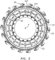
- the non-round swirler 114, 116 is elliptical, curve elliptical in cross section, or of other non-round shape to generate the non axis-symmetric (e.g., elliptical) fuel-air mixture pattern 104 ( FIG. 5 ).
- the adjective "elliptical" is used herein as an example swirler or swirler component having a major diameter extending in a radial direction greater than a minor diameter extending in a circumferential direction about the axis F.
- the non-round swirler 114, 116 includes an inner shroud 108 positioned around the fuel nozzle 100 to form a fuel air exit 109 and an outer shroud 110 positioned radially outward from the inner shroud 108 to define an air exit 113 ( FIG. 6 ).
- a fuel nozzle guide 111 may house the fuel nozzle 100 to form a rear housing in relation to the swirler body 114, 116 to retain the fuel nozzle 100 therein and to accommodate thermal excursions.
- a plurality of swirler vanes 112, 118 are positioned between the shrouds 108 and fuel nozzle guide 111 such that combustion air may enter into the combustion chamber through a plurality of air passages between the swirler vanes 112, 118.
- a first swirler 114 is positioned around the nozzle 100 as described above and a second swirler 116 is positioned radially outward from the first swirler 114.
- the inner shroud 108 and the outer shroud 110 of the second swirler 116 may be joined by a second plurality of vanes 118.
- the elliptical fuel-air mixture pattern 104 and resultant elliptical flame pattern may be beneficial compared to a fully conical axis-symmetric spray in that the elliptical fuel-air mixture pattern 104 orientation can be tailored to the combustion chamber ( FIG. 5 ).
- the combustor wall assemblies 60, 62 are essentially concentric rings that capture the flame for direction to the HPT 54.
- the elliptical flame pattern of each fuel air mixer assembly 102 is appropriately clocked to minimize impact on the combustor wall assemblies 60, 62 ( FIG. 6 ).
- the volume of the combustor is related to combustion efficiency, emissions, and ultimately, the exit temperature profile.
- the combustor wall assemblies 60, 62 often create a boundary and recirculation zone critical to ignition and flame stabilization, however the combustor wall assemblies 60, 62 can be impacted by the flame pattern which result in local hot spots.
- the non-round swirler 114, 116 maintains the inner and outer recirculation zones to facilitate flame stabilization while limiting the flame impact upon the combustor wall assemblies 60, 62.
- the non-round swirlers 114, 116 are arranged such that each of the elliptical spray patterns 104 are generally oriented such that a major axis 103 thereof is clocked around the engine axis A.
- Each of the elliptical spray patterns 104 is clocked to define a circular distribution in which the Z-axis thereof is collinear with the engine central longitudinal axis A in an X-Y-Z coordinate system.
- the engine central longitudinal axis A represents the Z-axis in the X-Y-Z coordinate system of the non-round swirler 114, 116 with respect to the arrangement of the elliptical spray pattern 104.
- each of the adjacent elliptical spray patterns 104 provides an overlap area 105 which facilitates a contiguous annular flame pattern while limiting the flame spread in the radial minor axis 107 direction to minimize a "touchdown region" on the surfaces of the inner and outer combustor wall assemblies 60, 62.
- the spray pattern of the fuel air mixture exiting the swirlers 114, 116 and thus the resulting flame is an elliptical, or curved elliptical shape that minimizes the impact against the inner and outer combustor wall assemblies 60, 62.
- the spreading of the fuel spray and flame radially around the annulus between the combustor wall assemblies 60, 62 provides a more uniform hot gas mixture as opposed to local conical hot spots with cooler areas therebetween, yet minimizes impact on the combustor wall assemblies 60, 62.
- the shape of the fuel spray and resulting flame can be tailored in shape by the swirler shape and/or air passages thereof as well as the fuel nozzle spray pattern. That is, the major axis 103 of the non-round swirler 114, 116 coincides with a major axis of the non-round fuel nozzle 100. Furthermore, the non-round fuel nozzle 100 can also be tailored or clocked with respect to the shape of the non-round swirler 114, 116 to further enhance circumferential mixing while minimizing flame touchdown size and shape. This may further minimize global cooling air usage as well as locally resulting in a far more durable system as well as enhanced combustion characteristics such as stability and exit temperature uniformity.
- the non-round fuel nozzle 100A is of an elliptical shape to correspond with the generally non-round swirler 114, 116 for further control of the spray pattern.
- the non-round fuel nozzle 100B is of a rectilinear or flat shape that is oriented with the generally non-round swirler 114, 116 for further control of the spray pattern.
- the non-round fuel nozzle 100C may alternatively include a multiple of fuel jets 200 that include fuel jets 200A, 200B that are of differing sizes to effect the non-round spray pattern. That is, the distribution of fuel jet sizes provides non axis-symmetric fuel spray pattern even though the fuel nozzle body 202 is round. That is, the fuel nozzle body 202 may be round or non-round but the fuel jets 200 are tailored in size to provide various fuel spray patterns to interact with the non-round swirler 114, 116 to optimize flame exit temperature uniformity.
- the non-round swirler 114, 116 orients the elliptical spray pattern 104 such that the flame has minimal impact on the combustor wall assemblies 60, 62. This can reduce the requirements for cooling air to maintain metal temperatures below the material melting point. Furthermore, reduced cooling air usage facilitates more efficient downstream tailoring of the exit temperature quality of the combustor to enhance overall engine efficiency and specific fuel consumption.
- the non-round swirler 114, 116 is non axis-symmetric, the circumferential distance between the swirlers 114, 116 ( FIG. 5 ) can also be optimized to improve exit temperature quality, which results in a hot gas profile that exits the combustor 66 in a more uniform manner. This, for example, translates to improved turbine vane and airfoil durability that may be a significant driver for engine maintenance costs.
Landscapes
- Engineering & Computer Science (AREA)
- Chemical & Material Sciences (AREA)
- Combustion & Propulsion (AREA)
- Mechanical Engineering (AREA)
- General Engineering & Computer Science (AREA)
Applications Claiming Priority (1)
| Application Number | Priority Date | Filing Date | Title |
|---|---|---|---|
| US15/599,252 US20180335214A1 (en) | 2017-05-18 | 2017-05-18 | Fuel air mixer assembly for a gas turbine engine combustor |
Publications (2)
| Publication Number | Publication Date |
|---|---|
| EP3404331A1 true EP3404331A1 (fr) | 2018-11-21 |
| EP3404331B1 EP3404331B1 (fr) | 2022-07-06 |
Family
ID=62200331
Family Applications (1)
| Application Number | Title | Priority Date | Filing Date |
|---|---|---|---|
| EP18173047.4A Active EP3404331B1 (fr) | 2017-05-18 | 2018-05-17 | Chambre de combustion de moteur de turbine à gaz comprenant un ensemble mélangeur air-carburant |
Country Status (2)
| Country | Link |
|---|---|
| US (1) | US20180335214A1 (fr) |
| EP (1) | EP3404331B1 (fr) |
Cited By (1)
| Publication number | Priority date | Publication date | Assignee | Title |
|---|---|---|---|---|
| CN110345513A (zh) * | 2019-07-12 | 2019-10-18 | 中国航发沈阳发动机研究所 | 一种分级燃烧的旋流雾化装置 |
Families Citing this family (8)
| Publication number | Priority date | Publication date | Assignee | Title |
|---|---|---|---|---|
| US10591163B2 (en) * | 2017-07-21 | 2020-03-17 | United Technologies Corporation | Swirler for combustor of gas turbine engine |
| GB201806631D0 (en) * | 2018-04-24 | 2018-06-06 | Rolls Royce Plc | A combustion chamber arrangement and a gas turbine engine comprising a combustion chamber arrangement |
| JP7446077B2 (ja) * | 2019-10-04 | 2024-03-08 | 三菱重工業株式会社 | ガスタービン用燃焼器、ガスタービン及び油燃料の燃焼方法 |
| US11378275B2 (en) * | 2019-12-06 | 2022-07-05 | Raytheon Technologies Corporation | High shear swirler with recessed fuel filmer for a gas turbine engine |
| CN112240568B (zh) * | 2020-09-11 | 2022-10-28 | 北京动力机械研究所 | 一种用于加热器稳定燃烧的水冷筒形整流器 |
| US11725824B2 (en) | 2021-04-08 | 2023-08-15 | Raytheon Technologies Corporation | Turbulence generator mixer for rotating detonation engine |
| US12092332B2 (en) * | 2021-12-29 | 2024-09-17 | General Electric Company | Fuel nozzle and swirler |
| FR3142533A1 (fr) * | 2022-11-28 | 2024-05-31 | Safran Aircraft Engines | Chambre de combustion pour turbomachine |
Citations (8)
| Publication number | Priority date | Publication date | Assignee | Title |
|---|---|---|---|---|
| US3622080A (en) * | 1968-07-09 | 1971-11-23 | Lucas Industries Ltd | Liquid spray nozzles |
| US3763650A (en) * | 1971-07-26 | 1973-10-09 | Westinghouse Electric Corp | Gas turbine temperature profiling structure |
| US5373694A (en) * | 1992-11-17 | 1994-12-20 | United Technologies Corporation | Combustor seal and support |
| US5937653A (en) * | 1996-07-11 | 1999-08-17 | Societe Nationale D'etude Et De Construction De Moteurs D'aviation (Snecma) | Reduced pollution combustion chamber having an annular fuel injector |
| EP2151630A1 (fr) * | 2008-08-04 | 2010-02-10 | Siemens Aktiengesellschaft | Dispositif de tourbillonnement et agencement d'un tel dispositif |
| US20140165578A1 (en) * | 2012-12-17 | 2014-06-19 | United Technologies Corporation | Ovate Swirler Assembly for Combustors |
| US20140165585A1 (en) * | 2012-12-17 | 2014-06-19 | United Technologies Corporation | Oblong Swirler Assembly for Combustors |
| EP3147571A1 (fr) * | 2015-09-25 | 2017-03-29 | Rolls-Royce plc | Injecteur de carburant pour chambre de combustion de moteur de turbine à gaz |
Family Cites Families (15)
| Publication number | Priority date | Publication date | Assignee | Title |
|---|---|---|---|---|
| US1445208A (en) * | 1920-12-30 | 1923-02-13 | Chauncey B Forward | Oil burner |
| US2012139A (en) * | 1933-07-24 | 1935-08-20 | Peabody Engineering Corp | Atomizer |
| US3521824A (en) * | 1968-10-11 | 1970-07-28 | Delavan Manufacturing Co | Air-liquid flat spray nozzle |
| US4218020A (en) * | 1979-02-23 | 1980-08-19 | General Motors Corporation | Elliptical airblast nozzle |
| US4991398A (en) * | 1989-01-12 | 1991-02-12 | United Technologies Corporation | Combustor fuel nozzle arrangement |
| US6119459A (en) * | 1998-08-18 | 2000-09-19 | Alliedsignal Inc. | Elliptical axial combustor swirler |
| DE10348604A1 (de) * | 2003-10-20 | 2005-07-28 | Rolls-Royce Deutschland Ltd & Co Kg | Kraftstoffeinspritzdüse mit filmartiger Kraftstoffplatzierung |
| DE102006032429A1 (de) * | 2006-07-13 | 2008-02-21 | Rolls-Royce Deutschland Ltd & Co Kg | Kraftstoffeinspritzvorrichtung für eine Fluggasturbine |
| US8474265B2 (en) * | 2009-07-29 | 2013-07-02 | General Electric Company | Fuel nozzle for a turbine combustor, and methods of forming same |
| US9366440B2 (en) * | 2012-01-04 | 2016-06-14 | General Electric Company | Fuel nozzles with mixing tubes surrounding a liquid fuel cartridge for injecting fuel in a gas turbine combustor |
| DE102012002465A1 (de) * | 2012-02-08 | 2013-08-08 | Rolls-Royce Deutschland Ltd & Co Kg | Gasturbinenbrennkammer mit unsymmetrischen Kraftstoffdüsen |
| US9322336B2 (en) * | 2012-12-06 | 2016-04-26 | General Electric Company | Fuel nozzle for gas turbine |
| GB201222304D0 (en) * | 2012-12-12 | 2013-01-23 | Rolls Royce Plc | A fuel injector and a gas turbine engine combustion chamber |
| US9791153B2 (en) * | 2015-02-27 | 2017-10-17 | United Technologies Corporation | Line replaceable fuel nozzle apparatus, system and method |
| US20170003023A1 (en) * | 2015-07-01 | 2017-01-05 | Profire Energy, Inc | Dual trim valve cartridge and system |
-
2017
- 2017-05-18 US US15/599,252 patent/US20180335214A1/en not_active Abandoned
-
2018
- 2018-05-17 EP EP18173047.4A patent/EP3404331B1/fr active Active
Patent Citations (8)
| Publication number | Priority date | Publication date | Assignee | Title |
|---|---|---|---|---|
| US3622080A (en) * | 1968-07-09 | 1971-11-23 | Lucas Industries Ltd | Liquid spray nozzles |
| US3763650A (en) * | 1971-07-26 | 1973-10-09 | Westinghouse Electric Corp | Gas turbine temperature profiling structure |
| US5373694A (en) * | 1992-11-17 | 1994-12-20 | United Technologies Corporation | Combustor seal and support |
| US5937653A (en) * | 1996-07-11 | 1999-08-17 | Societe Nationale D'etude Et De Construction De Moteurs D'aviation (Snecma) | Reduced pollution combustion chamber having an annular fuel injector |
| EP2151630A1 (fr) * | 2008-08-04 | 2010-02-10 | Siemens Aktiengesellschaft | Dispositif de tourbillonnement et agencement d'un tel dispositif |
| US20140165578A1 (en) * | 2012-12-17 | 2014-06-19 | United Technologies Corporation | Ovate Swirler Assembly for Combustors |
| US20140165585A1 (en) * | 2012-12-17 | 2014-06-19 | United Technologies Corporation | Oblong Swirler Assembly for Combustors |
| EP3147571A1 (fr) * | 2015-09-25 | 2017-03-29 | Rolls-Royce plc | Injecteur de carburant pour chambre de combustion de moteur de turbine à gaz |
Cited By (1)
| Publication number | Priority date | Publication date | Assignee | Title |
|---|---|---|---|---|
| CN110345513A (zh) * | 2019-07-12 | 2019-10-18 | 中国航发沈阳发动机研究所 | 一种分级燃烧的旋流雾化装置 |
Also Published As
| Publication number | Publication date |
|---|---|
| EP3404331B1 (fr) | 2022-07-06 |
| US20180335214A1 (en) | 2018-11-22 |
Similar Documents
| Publication | Publication Date | Title |
|---|---|---|
| EP3404331B1 (fr) | Chambre de combustion de moteur de turbine à gaz comprenant un ensemble mélangeur air-carburant | |
| EP3008391B1 (fr) | Chambre de combustion à étagement axial pour un moteur à turbine à gaz | |
| US11156359B2 (en) | Combustor liner panel end rail with diffused interface passage for a gas turbine engine combustor | |
| US10738704B2 (en) | Pilot/main fuel shifting in an axial staged combustor for a gas turbine engine | |
| US10436449B2 (en) | Light weight swirler for gas turbine engine combustor and a method for lightening a swirler for a gas turbine engine | |
| EP3301372B1 (fr) | Polarisation et décalage de carburant circonférentiels dans une chambre de combustion étagée axiale pour un moteur à turbine à gaz | |
| US11365884B2 (en) | Radial fuel shifting and biasing in an axial staged combustor for a gas turbine engine | |
| US10386070B2 (en) | Multi-streamed dilution hole configuration for a gas turbine engine | |
| EP3333486B1 (fr) | Mélangeur principal pour chambre de combustion d'un moteur à turbine à gaz | |
| US9404657B2 (en) | Combuster with radial fuel injection | |
| US11226102B2 (en) | Fuel nozzle for a gas turbine engine | |
| US10830433B2 (en) | Axial non-linear interface for combustor liner panels in a gas turbine combustor | |
| US10935235B2 (en) | Non-planar combustor liner panel for a gas turbine engine combustor | |
| US10655853B2 (en) | Combustor liner panel with non-linear circumferential edge for a gas turbine engine combustor |
Legal Events
| Date | Code | Title | Description |
|---|---|---|---|
| PUAI | Public reference made under article 153(3) epc to a published international application that has entered the european phase |
Free format text: ORIGINAL CODE: 0009012 |
|
| STAA | Information on the status of an ep patent application or granted ep patent |
Free format text: STATUS: THE APPLICATION HAS BEEN PUBLISHED |
|
| AK | Designated contracting states |
Kind code of ref document: A1 Designated state(s): AL AT BE BG CH CY CZ DE DK EE ES FI FR GB GR HR HU IE IS IT LI LT LU LV MC MK MT NL NO PL PT RO RS SE SI SK SM TR |
|
| AX | Request for extension of the european patent |
Extension state: BA ME |
|
| STAA | Information on the status of an ep patent application or granted ep patent |
Free format text: STATUS: REQUEST FOR EXAMINATION WAS MADE |
|
| 17P | Request for examination filed |
Effective date: 20190521 |
|
| RBV | Designated contracting states (corrected) |
Designated state(s): AL AT BE BG CH CY CZ DE DK EE ES FI FR GB GR HR HU IE IS IT LI LT LU LV MC MK MT NL NO PL PT RO RS SE SI SK SM TR |
|
| STAA | Information on the status of an ep patent application or granted ep patent |
Free format text: STATUS: EXAMINATION IS IN PROGRESS |
|
| 17Q | First examination report despatched |
Effective date: 20200619 |
|
| STAA | Information on the status of an ep patent application or granted ep patent |
Free format text: STATUS: EXAMINATION IS IN PROGRESS |
|
| RAP1 | Party data changed (applicant data changed or rights of an application transferred) |
Owner name: RAYTHEON TECHNOLOGIES CORPORATION |
|
| GRAP | Despatch of communication of intention to grant a patent |
Free format text: ORIGINAL CODE: EPIDOSNIGR1 |
|
| STAA | Information on the status of an ep patent application or granted ep patent |
Free format text: STATUS: GRANT OF PATENT IS INTENDED |
|
| INTG | Intention to grant announced |
Effective date: 20210624 |
|
| GRAJ | Information related to disapproval of communication of intention to grant by the applicant or resumption of examination proceedings by the epo deleted |
Free format text: ORIGINAL CODE: EPIDOSDIGR1 |
|
| STAA | Information on the status of an ep patent application or granted ep patent |
Free format text: STATUS: EXAMINATION IS IN PROGRESS |
|
| INTC | Intention to grant announced (deleted) | ||
| GRAJ | Information related to disapproval of communication of intention to grant by the applicant or resumption of examination proceedings by the epo deleted |
Free format text: ORIGINAL CODE: EPIDOSDIGR1 |
|
| STAA | Information on the status of an ep patent application or granted ep patent |
Free format text: STATUS: GRANT OF PATENT IS INTENDED |
|
| GRAP | Despatch of communication of intention to grant a patent |
Free format text: ORIGINAL CODE: EPIDOSNIGR1 |
|
| INTG | Intention to grant announced |
Effective date: 20220114 |
|
| GRAS | Grant fee paid |
Free format text: ORIGINAL CODE: EPIDOSNIGR3 |
|
| GRAA | (expected) grant |
Free format text: ORIGINAL CODE: 0009210 |
|
| STAA | Information on the status of an ep patent application or granted ep patent |
Free format text: STATUS: THE PATENT HAS BEEN GRANTED |
|
| AK | Designated contracting states |
Kind code of ref document: B1 Designated state(s): AL AT BE BG CH CY CZ DE DK EE ES FI FR GB GR HR HU IE IS IT LI LT LU LV MC MK MT NL NO PL PT RO RS SE SI SK SM TR |
|
| REG | Reference to a national code |
Ref country code: AT Ref legal event code: REF Ref document number: 1503103 Country of ref document: AT Kind code of ref document: T Effective date: 20220715 Ref country code: CH Ref legal event code: EP |
|
| REG | Reference to a national code |
Ref country code: DE Ref legal event code: R096 Ref document number: 602018037490 Country of ref document: DE |
|
| REG | Reference to a national code |
Ref country code: IE Ref legal event code: FG4D |
|
| REG | Reference to a national code |
Ref country code: LT Ref legal event code: MG9D |
|
| REG | Reference to a national code |
Ref country code: NL Ref legal event code: MP Effective date: 20220706 |
|
| PG25 | Lapsed in a contracting state [announced via postgrant information from national office to epo] |
Ref country code: SE Free format text: LAPSE BECAUSE OF FAILURE TO SUBMIT A TRANSLATION OF THE DESCRIPTION OR TO PAY THE FEE WITHIN THE PRESCRIBED TIME-LIMIT Effective date: 20220706 Ref country code: RS Free format text: LAPSE BECAUSE OF FAILURE TO SUBMIT A TRANSLATION OF THE DESCRIPTION OR TO PAY THE FEE WITHIN THE PRESCRIBED TIME-LIMIT Effective date: 20220706 Ref country code: PT Free format text: LAPSE BECAUSE OF FAILURE TO SUBMIT A TRANSLATION OF THE DESCRIPTION OR TO PAY THE FEE WITHIN THE PRESCRIBED TIME-LIMIT Effective date: 20221107 Ref country code: NO Free format text: LAPSE BECAUSE OF FAILURE TO SUBMIT A TRANSLATION OF THE DESCRIPTION OR TO PAY THE FEE WITHIN THE PRESCRIBED TIME-LIMIT Effective date: 20221006 Ref country code: NL Free format text: LAPSE BECAUSE OF FAILURE TO SUBMIT A TRANSLATION OF THE DESCRIPTION OR TO PAY THE FEE WITHIN THE PRESCRIBED TIME-LIMIT Effective date: 20220706 Ref country code: LV Free format text: LAPSE BECAUSE OF FAILURE TO SUBMIT A TRANSLATION OF THE DESCRIPTION OR TO PAY THE FEE WITHIN THE PRESCRIBED TIME-LIMIT Effective date: 20220706 Ref country code: LT Free format text: LAPSE BECAUSE OF FAILURE TO SUBMIT A TRANSLATION OF THE DESCRIPTION OR TO PAY THE FEE WITHIN THE PRESCRIBED TIME-LIMIT Effective date: 20220706 Ref country code: FI Free format text: LAPSE BECAUSE OF FAILURE TO SUBMIT A TRANSLATION OF THE DESCRIPTION OR TO PAY THE FEE WITHIN THE PRESCRIBED TIME-LIMIT Effective date: 20220706 Ref country code: ES Free format text: LAPSE BECAUSE OF FAILURE TO SUBMIT A TRANSLATION OF THE DESCRIPTION OR TO PAY THE FEE WITHIN THE PRESCRIBED TIME-LIMIT Effective date: 20220706 |
|
| REG | Reference to a national code |
Ref country code: AT Ref legal event code: MK05 Ref document number: 1503103 Country of ref document: AT Kind code of ref document: T Effective date: 20220706 |
|
| PG25 | Lapsed in a contracting state [announced via postgrant information from national office to epo] |
Ref country code: PL Free format text: LAPSE BECAUSE OF FAILURE TO SUBMIT A TRANSLATION OF THE DESCRIPTION OR TO PAY THE FEE WITHIN THE PRESCRIBED TIME-LIMIT Effective date: 20220706 Ref country code: IS Free format text: LAPSE BECAUSE OF FAILURE TO SUBMIT A TRANSLATION OF THE DESCRIPTION OR TO PAY THE FEE WITHIN THE PRESCRIBED TIME-LIMIT Effective date: 20221106 Ref country code: HR Free format text: LAPSE BECAUSE OF FAILURE TO SUBMIT A TRANSLATION OF THE DESCRIPTION OR TO PAY THE FEE WITHIN THE PRESCRIBED TIME-LIMIT Effective date: 20220706 Ref country code: GR Free format text: LAPSE BECAUSE OF FAILURE TO SUBMIT A TRANSLATION OF THE DESCRIPTION OR TO PAY THE FEE WITHIN THE PRESCRIBED TIME-LIMIT Effective date: 20221007 |
|
| REG | Reference to a national code |
Ref country code: DE Ref legal event code: R097 Ref document number: 602018037490 Country of ref document: DE |
|
| PG25 | Lapsed in a contracting state [announced via postgrant information from national office to epo] |
Ref country code: SM Free format text: LAPSE BECAUSE OF FAILURE TO SUBMIT A TRANSLATION OF THE DESCRIPTION OR TO PAY THE FEE WITHIN THE PRESCRIBED TIME-LIMIT Effective date: 20220706 Ref country code: RO Free format text: LAPSE BECAUSE OF FAILURE TO SUBMIT A TRANSLATION OF THE DESCRIPTION OR TO PAY THE FEE WITHIN THE PRESCRIBED TIME-LIMIT Effective date: 20220706 Ref country code: DK Free format text: LAPSE BECAUSE OF FAILURE TO SUBMIT A TRANSLATION OF THE DESCRIPTION OR TO PAY THE FEE WITHIN THE PRESCRIBED TIME-LIMIT Effective date: 20220706 Ref country code: CZ Free format text: LAPSE BECAUSE OF FAILURE TO SUBMIT A TRANSLATION OF THE DESCRIPTION OR TO PAY THE FEE WITHIN THE PRESCRIBED TIME-LIMIT Effective date: 20220706 Ref country code: AT Free format text: LAPSE BECAUSE OF FAILURE TO SUBMIT A TRANSLATION OF THE DESCRIPTION OR TO PAY THE FEE WITHIN THE PRESCRIBED TIME-LIMIT Effective date: 20220706 |
|
| PLBE | No opposition filed within time limit |
Free format text: ORIGINAL CODE: 0009261 |
|
| STAA | Information on the status of an ep patent application or granted ep patent |
Free format text: STATUS: NO OPPOSITION FILED WITHIN TIME LIMIT |
|
| PG25 | Lapsed in a contracting state [announced via postgrant information from national office to epo] |
Ref country code: SK Free format text: LAPSE BECAUSE OF FAILURE TO SUBMIT A TRANSLATION OF THE DESCRIPTION OR TO PAY THE FEE WITHIN THE PRESCRIBED TIME-LIMIT Effective date: 20220706 Ref country code: EE Free format text: LAPSE BECAUSE OF FAILURE TO SUBMIT A TRANSLATION OF THE DESCRIPTION OR TO PAY THE FEE WITHIN THE PRESCRIBED TIME-LIMIT Effective date: 20220706 |
|
| 26N | No opposition filed |
Effective date: 20230411 |
|
| P01 | Opt-out of the competence of the unified patent court (upc) registered |
Effective date: 20230521 |
|
| PG25 | Lapsed in a contracting state [announced via postgrant information from national office to epo] |
Ref country code: AL Free format text: LAPSE BECAUSE OF FAILURE TO SUBMIT A TRANSLATION OF THE DESCRIPTION OR TO PAY THE FEE WITHIN THE PRESCRIBED TIME-LIMIT Effective date: 20220706 |
|
| PG25 | Lapsed in a contracting state [announced via postgrant information from national office to epo] |
Ref country code: SI Free format text: LAPSE BECAUSE OF FAILURE TO SUBMIT A TRANSLATION OF THE DESCRIPTION OR TO PAY THE FEE WITHIN THE PRESCRIBED TIME-LIMIT Effective date: 20220706 |
|
| REG | Reference to a national code |
Ref country code: CH Ref legal event code: PL |
|
| PG25 | Lapsed in a contracting state [announced via postgrant information from national office to epo] |
Ref country code: MC Free format text: LAPSE BECAUSE OF FAILURE TO SUBMIT A TRANSLATION OF THE DESCRIPTION OR TO PAY THE FEE WITHIN THE PRESCRIBED TIME-LIMIT Effective date: 20220706 |
|
| REG | Reference to a national code |
Ref country code: BE Ref legal event code: MM Effective date: 20230531 |
|
| PG25 | Lapsed in a contracting state [announced via postgrant information from national office to epo] |
Ref country code: MC Free format text: LAPSE BECAUSE OF FAILURE TO SUBMIT A TRANSLATION OF THE DESCRIPTION OR TO PAY THE FEE WITHIN THE PRESCRIBED TIME-LIMIT Effective date: 20220706 Ref country code: LU Free format text: LAPSE BECAUSE OF NON-PAYMENT OF DUE FEES Effective date: 20230517 Ref country code: LI Free format text: LAPSE BECAUSE OF NON-PAYMENT OF DUE FEES Effective date: 20230531 Ref country code: IT Free format text: LAPSE BECAUSE OF FAILURE TO SUBMIT A TRANSLATION OF THE DESCRIPTION OR TO PAY THE FEE WITHIN THE PRESCRIBED TIME-LIMIT Effective date: 20220706 Ref country code: CH Free format text: LAPSE BECAUSE OF NON-PAYMENT OF DUE FEES Effective date: 20230531 |
|
| REG | Reference to a national code |
Ref country code: IE Ref legal event code: MM4A |
|
| PG25 | Lapsed in a contracting state [announced via postgrant information from national office to epo] |
Ref country code: IE Free format text: LAPSE BECAUSE OF NON-PAYMENT OF DUE FEES Effective date: 20230517 |
|
| PG25 | Lapsed in a contracting state [announced via postgrant information from national office to epo] |
Ref country code: IE Free format text: LAPSE BECAUSE OF NON-PAYMENT OF DUE FEES Effective date: 20230517 |
|
| PG25 | Lapsed in a contracting state [announced via postgrant information from national office to epo] |
Ref country code: BE Free format text: LAPSE BECAUSE OF NON-PAYMENT OF DUE FEES Effective date: 20230531 |
|
| PGFP | Annual fee paid to national office [announced via postgrant information from national office to epo] |
Ref country code: GB Payment date: 20240418 Year of fee payment: 7 |
|
| PGFP | Annual fee paid to national office [announced via postgrant information from national office to epo] |
Ref country code: DE Payment date: 20240418 Year of fee payment: 7 |
|
| PGFP | Annual fee paid to national office [announced via postgrant information from national office to epo] |
Ref country code: FR Payment date: 20240418 Year of fee payment: 7 |