EP3404232A1 - Connecting rod for a combustion engine with variable compression - Google Patents
Connecting rod for a combustion engine with variable compression Download PDFInfo
- Publication number
- EP3404232A1 EP3404232A1 EP18168723.7A EP18168723A EP3404232A1 EP 3404232 A1 EP3404232 A1 EP 3404232A1 EP 18168723 A EP18168723 A EP 18168723A EP 3404232 A1 EP3404232 A1 EP 3404232A1
- Authority
- EP
- European Patent Office
- Prior art keywords
- connecting rod
- bore
- closing element
- valve seat
- combustion engine
- Prior art date
- Legal status (The legal status is an assumption and is not a legal conclusion. Google has not performed a legal analysis and makes no representation as to the accuracy of the status listed.)
- Granted
Links
Images


Classifications
-
- F—MECHANICAL ENGINEERING; LIGHTING; HEATING; WEAPONS; BLASTING
- F02—COMBUSTION ENGINES; HOT-GAS OR COMBUSTION-PRODUCT ENGINE PLANTS
- F02B—INTERNAL-COMBUSTION PISTON ENGINES; COMBUSTION ENGINES IN GENERAL
- F02B75/00—Other engines
- F02B75/04—Engines with variable distances between pistons at top dead-centre positions and cylinder heads
- F02B75/045—Engines with variable distances between pistons at top dead-centre positions and cylinder heads by means of a variable connecting rod length
-
- F—MECHANICAL ENGINEERING; LIGHTING; HEATING; WEAPONS; BLASTING
- F16—ENGINEERING ELEMENTS AND UNITS; GENERAL MEASURES FOR PRODUCING AND MAINTAINING EFFECTIVE FUNCTIONING OF MACHINES OR INSTALLATIONS; THERMAL INSULATION IN GENERAL
- F16K—VALVES; TAPS; COCKS; ACTUATING-FLOATS; DEVICES FOR VENTING OR AERATING
- F16K15/00—Check valves
- F16K15/02—Check valves with guided rigid valve members
- F16K15/021—Check valves with guided rigid valve members the valve member being a movable body around which the medium flows when the valve is open
- F16K15/023—Check valves with guided rigid valve members the valve member being a movable body around which the medium flows when the valve is open the valve member consisting only of a predominantly disc-shaped flat element
-
- F—MECHANICAL ENGINEERING; LIGHTING; HEATING; WEAPONS; BLASTING
- F16—ENGINEERING ELEMENTS AND UNITS; GENERAL MEASURES FOR PRODUCING AND MAINTAINING EFFECTIVE FUNCTIONING OF MACHINES OR INSTALLATIONS; THERMAL INSULATION IN GENERAL
- F16K—VALVES; TAPS; COCKS; ACTUATING-FLOATS; DEVICES FOR VENTING OR AERATING
- F16K15/00—Check valves
- F16K15/02—Check valves with guided rigid valve members
- F16K15/04—Check valves with guided rigid valve members shaped as balls
Landscapes
- Engineering & Computer Science (AREA)
- General Engineering & Computer Science (AREA)
- Mechanical Engineering (AREA)
- Chemical & Material Sciences (AREA)
- Combustion & Propulsion (AREA)
- Output Control And Ontrol Of Special Type Engine (AREA)
- Shafts, Cranks, Connecting Bars, And Related Bearings (AREA)
Abstract
Die Erfindung betrifft einen Pleuel (1) für eine Brennkraftmaschine mit variabler Verdichtung mit wenigstens einer in einem Pleuelkörper (19) ausgebildeten Hydraulikkammer (10, 11), wobei die Hydraulikkammer (10, 11) mittels eines Rückschlagventils (14, 15) mit einer Lagerschale (16) des Pleuels (1) bzw. einem Tank verbindbar ist, wobei das Rückschlagventil (14, 15) ein Schließelement (20) und ein Ventilsitz (21) umfasst, welches Schließelement (20) in Sperrstellung einen Fluidpfad durch Anlage an den Ventilsitz (21) sperrt. Erfindungsgemäß ist der Schließkörper (20) in einer Bohrung (22) des Pleuelkörpers (19) angeordnet und der Ventilsitz (21) ist in den Pleuelkörper (19) eingebracht vorgesehen. Ferner betrifft die Erfindung eine Brennkraftmaschine mit einem einstellbaren Verdichtungsverhältnis mit wenigstens einem Pleuel (1).The invention relates to a connecting rod (1) for an internal combustion engine with variable compression with at least one in a connecting rod body (19) formed hydraulic chamber (10, 11), wherein the hydraulic chamber (10, 11) by means of a check valve (14, 15) with a bearing shell (16) of the connecting rod (1) or a tank can be connected, wherein the check valve (14, 15) comprises a closing element (20) and a valve seat (21), which closing element (20) in the blocking position a fluid path by contact with the valve seat (21) locks. According to the invention, the closing body (20) is arranged in a bore (22) of the connecting-rod body (19) and the valve seat (21) is provided in the connecting-rod body (19). Furthermore, the invention relates to an internal combustion engine with an adjustable compression ratio with at least one connecting rod (1).
Description
Die Erfindung betrifft einen Pleuel für eine Brennkraftmaschine mit variabler Verdichtung mit wenigstens einer in einem Pleuelkörper ausgebildeten Hydraulikkammer, wobei die Hydraulikkammer mittels eines Rückschlagventils mit einer Lagerschale des Pleuels bzw. einem Tank verbindbar ist, wobei das Rückschlagventil ein Schließelement und ein Ventilsitz umfasst, welches Schließelement in Sperrstellung einen Fluidpfad durch Anlage an den Ventilsitz sperrt. Ferner betrifft die Erfindung eine Brennkraftmaschine mit einem einstellbaren Verdichtungsverhältnis mit wenigstens einem Pleuel.The invention relates to a connecting rod for a variable compression internal combustion engine having at least one hydraulic chamber formed in a connecting rod body, wherein the hydraulic chamber by means of a check valve with a bearing shell of the connecting rod or a tank is connectable, wherein the check valve comprises a closing element and a valve seat, which closing element blocked in the blocking position a fluid path by contact with the valve seat. Furthermore, the invention relates to an internal combustion engine with an adjustable compression ratio with at least one connecting rod.
Bei Brennkraftmaschinen wirkt sich ein hohes Verdichtungsverhältnis positiv auf den Wirkungsgrad der Brennkraftmaschine aus. Unter Verdichtungsverhältnis wird im Allgemeinen das Verhältnis des gesamten Zylinderraumes vor der Verdichtung zum verbliebenen Zylinderraum nach der Verdichtung verstanden. Bei Brennkraftmaschinen mit Fremdzündung, insbesondere Ottomotoren, die ein festes Verdichtungsverhältnis aufweisen, darf das Verdichtungsverhältnis jedoch nur so hoch gewählt werden, dass bei Volllastbetrieb ein sogenanntes "Klopfen" der Brennkraftmaschine vermieden wird. Jedoch könnte für den weitaus häufiger auftretenden Teillastbereich der Brennkraftmaschine, also bei geringer Zylinderfüllung, das Verdichtungsverhältnis mit höheren Werten gewählt werden, ohne dass ein "Klopfen" auftreten würde. Der wichtige Teillastbereich einer Brennkraftmaschine kann verbessert werden, wenn das Verdichtungsverhältnis variabel einstellbar ist. Zur Verstellung des Verdichtungsverhältnisses sind beispielsweise Systeme mit variabler Pleuelstangenlänge bekannt, welche mit Hilfe von hydraulisch oder mechanisch betätigbaren Umschaltventilen eine Exzenter-Verstelleinrichtung eines Pleuels betätigen.In internal combustion engines, a high compression ratio has a positive effect on the efficiency of the internal combustion engine. Under compression ratio is generally understood the ratio of the entire cylinder space before compression to the remaining cylinder space after compression. In internal combustion engines with spark ignition, in particular gasoline engines, which have a fixed compression ratio, the compression ratio, however, may only be selected so high that a so-called "knocking" of the internal combustion engine is avoided during full load operation. However, for the far more frequently occurring partial load range of the internal combustion engine, ie at lower Cylinder filling, the compression ratio with higher values are selected without a "knocking" would occur. The important part load range of an internal combustion engine can be improved if the compression ratio is variably adjustable. To adjust the compression ratio, systems with variable connecting rod length are known, for example, which actuate an eccentric adjustment of a connecting rod with the aid of hydraulically or mechanically operated changeover valves.
Ein derartiger Pleuel ist beispielsweise aus der
Eine Aufgabe der Erfindung ist es, einen verbesserten Pleuel zu schaffen, welcher eine große Zuverlässigkeit, eine hohe Lebensdauer aufweist und gleichzeitig eine vereinfachte und damit kostengünstige Herstellung und Montage erlaubt.An object of the invention is to provide an improved connecting rod, which has a high reliability, a long service life and at the same time allows a simplified and thus cost-effective production and assembly.
Eine weitere Aufgabe der Erfindung ist es, eine verbesserte Brennkraftmaschine mit einem einstellbaren Verdichtungsverhältnis mit einem Pleuel anzubieten, welche einfach und kostengünstig ausgestaltet ist.Another object of the invention is to provide an improved internal combustion engine with an adjustable compression ratio with a connecting rod, which is simple and inexpensive.
Die vorgenannten Aufgaben werden nach einem Aspekt der Erfindung gelöst mit den Merkmalen der unabhängigen Ansprüche.The above objects are achieved according to one aspect of the invention with the features of the independent claims.
Günstige Ausgestaltungen und Vorteile der Erfindung ergeben sich aus den weiteren Ansprüchen, der Beschreibung und der Zeichnung.Favorable embodiments and advantages of the invention will become apparent from the other claims, the description and the drawings.
Es wird ein Pleuel für eine Brennkraftmaschine mit variabler Verdichtung mit wenigstens einer Hydraulikkammer vorgeschlagen, wobei die Hydraulikkammer mittels eines Rückschlagventils mit einer Lagerschale des Pleuels bzw. einem Tank verbindbar ist. Das Rückschlagventil umfasst einen Schließkörper und einen Ventilsitz. Das Schließelement sperrt in Sperrstellung einen Fluidpfad durch Anlage an den Ventilsitz. Dabei ist der Schließkörper in einer Bohrung des Pleuelkörpers angeordnet und der Ventilsitz ist in den Pleuelkörper eingebracht vorgesehen ist. Das Rückschlagventil besteht hierdurch aus möglichst wenigen Bauteilen, so dass der Pleuel besonders kostengünstig vorgesehen werden kann. Zusätzliche Montagevorgänge können erfindungsgemäß entfallen.It is proposed a connecting rod for an internal combustion engine with variable compression with at least one hydraulic chamber, wherein the hydraulic chamber by means of a check valve with a bearing shell of the connecting rod or a tank is connectable. The check valve comprises a closing body and a valve seat. The closing element locks in the blocking position a fluid path by contact with the valve seat. In this case, the closing body is arranged in a bore of the connecting rod body and the valve seat is provided introduced into the connecting rod body. The check valve consists of as few components as possible, so that the connecting rod can be provided particularly cost. Additional assembly operations can be omitted according to the invention.
Der erfindungsgemäße Pleuel für eine Brennkraftmaschine mit variabler Verdichtung kann beispielsweise eine Exzenter-Verstelleinrichtung zur Verstellung einer effektiven Pleuelstangenlänge umfassen. Ein Verstellweg der Exzenter-Verstelleinrichtung kann dabei mittels eines Umschaltventils verstellbar vorgesehen sein.The connecting rod according to the invention for a variable compression internal combustion engine may comprise, for example, an eccentric adjusting device for adjusting an effective connecting rod length. An adjustment of the eccentric adjusting device can be provided adjustable by means of a switching valve.
Ein Verdrehen der verstellbaren Exzenter-Verstelleinrichtung wird durch Einwirken von Massen- und Lastkräften der Brennkraftmaschine initiiert, die bei einem Arbeitstakt der Brennkraftmaschine auf die Exzenter-Verstelleinrichtung wirken. Während eines Arbeitstaktes verändern sich die Wirkungsrichtungen der auf die Exzenter-Verstelleinrichtung wirkenden Kräfte kontinuierlich. Die Drehbewegung oder Verstellbewegung wird durch wenigstens einen mit Hydraulikfluid, insbesondere mit Motoröl, beaufschlagten, in der Hydraulikkammer geführten Kolben unterstützt, bzw. der Kolben verhindert ein Rückstellen der Exzenter-Verstelleinrichtung aufgrund variierender Kraftwirkungsrichtungen der auf die Exzenter-Verstelleinrichtung wirkenden Kräfte.A rotation of the adjustable eccentric adjusting device is initiated by the action of mass and load forces of the internal combustion engine, which act on the eccentric adjusting device at a power stroke of the internal combustion engine. During a power stroke, the directions of action of the force acting on the eccentric adjusting forces change continuously. The rotational movement or adjusting movement is assisted by at least one piston acted upon by hydraulic fluid, in particular by engine oil, guided in the hydraulic chamber, or the piston prevents the eccentric adjusting device from returning varying force action directions of the force acting on the eccentric adjusting forces.
Die Kolben sind in Hydraulikkammern verschiebbar angeordnet und über Hydraulikfluidleitungen von der Lagerschale eines Hublagerauges oder einem Tank aus mit Hydraulikfluid über Rückschlagventile beaufschlagt. Diese verhindern dabei ein Rückfließen des Hydraulikfluids aus den Hydraulikkammern zurück in die Hydraulikfluidleitungen in die Lagerschale des Hublagerauges, bzw. einen Tank und ermöglichen ein Nachsaugen von Hydraulikfluid in die Hydraulikkammern.The pistons are slidably disposed in hydraulic chambers and acted upon via hydraulic fluid lines from the bearing shell of a Hubagerauges or a tank with hydraulic fluid via check valves. These prevent a backflow of the hydraulic fluid from the hydraulic chambers back into the hydraulic fluid lines in the bearing shell of the Hublagerauges, or a tank and allow a Nachsaugen of hydraulic fluid in the hydraulic chambers.
Vorzugsweise schließt sich die Bohrung direkt an die Hydraulikkammer an. Hierdurch kann die Bohrung in einem Arbeitsvorgang mit der Herstellung der Hydraulikkammer hergestellt werden und eine separate Einlassleitung zwischen dem Rückschlagventil und der Hydraulikkammer kann entfallen.Preferably, the bore connects directly to the hydraulic chamber. As a result, the bore can be produced in one operation with the production of the hydraulic chamber and a separate inlet line between the check valve and the hydraulic chamber can be omitted.
Das Schließelement kann beispielsweise als Kugel ausgebildet sein und der Ventilsitz kann wenigstens teilweise als konkav ausgebildeter Boden der Bohrung vorgesehen sein. Dabei ist die Kugel wie üblich aus Metall gefertigt, wobei auch ein Keramik-Schließelement auf Grund des niedrigen Gewichts und der hohen Verschleißfestigkeit vorteilhaft sein kann. Der Ventilsitz kann direkt im Pleuelkörper vorgesehen und bei der Herstellung der Bohrung ausgebildet sein. Vorteilhafterweise wird der Ventilsitz in einem einzigen Arbeitsgang mit der Bohrung hergestellt.The closing element may for example be formed as a ball and the valve seat may be at least partially provided as a concave bottom of the bore. The ball is made as usual from metal, whereby a ceramic closure element may be advantageous due to the low weight and high wear resistance. The valve seat can be provided directly in the connecting rod body and formed during the production of the bore. Advantageously, the valve seat is made in a single operation with the bore.
Eine alternative Ausführungsform sieht vor, dass das Schließelement als Platte ausgebildet ist. Der Ventilsitz dieser Ausführungsform wird als flächiger Boden vorgesehen.An alternative embodiment provides that the closing element is designed as a plate. The valve seat of this embodiment is provided as a flat bottom.
Um ein Durchströmen des Rückschlagventils zu gewährleisten, weist das Schließelement einen geringeren Durchmesser als die Bohrung auf und zwischen dem Schließelement und der Bohrung ist damit ein bestimmtes Spiel vorgesehen.In order to ensure a flow through the check valve, the closing element has a smaller diameter than the bore and between the closing element and the bore so that a certain game is provided.
Falls es erforderlich ist, das Spiel zwischen Schließelement und Bohrung zu begrenzen, kann das Schließelement ein oder mehrere Überströmkanäle aufweisen.If it is necessary to limit the play between closing element and bore, the closing element can have one or more overflow channels.
Die Überströmkanäle ermöglichen somit bei gleichzeitig geringem Spiel zwischen Schließelement und Bohrung einen erforderlichen Hydraulikfluidstrom.The overflow thus allow a small amount of clearance between the closing element and bore a required hydraulic fluid flow.
Gemäß einer vorteilhaften Ausführungsform der Erfindung ist das Schließelement in einem in der Bohrung angeordnetem Einlegeelement geführt vorgesehen, wobei das Einlegeelement Strömungsaussparungen aufweist, wodurch insbesondere beim Einsatz einer Kugel als Schließelement ein ausreichender Fluidstrom sichergestellt werden kann, ohne eine Führung der Kugel zu verschlechtern.According to an advantageous embodiment of the invention, the closing element is provided guided in an insertion element arranged in the bore, wherein the insert element has flow recesses, whereby a sufficient fluid flow can be ensured in particular when using a ball as the closing element, without deteriorating a leadership of the ball.
Vorzugsweise kann ein Hubbegrenzungsmittel in dem Pleuelkörper angeordnet sein, welches den Hub des Schließelementes innerhalb der Bohrung begrenzt, so dass ein Herausfallen des Schließelementes verhindert und gleichzeitig ein schnelles Schließen des Rückschlagventils sichergestellt werden können.Preferably, a Hubbegrenzungsmittel can be arranged in the Pleuelkörper, which limits the stroke of the closing element within the bore, so that a falling out of the closing element prevents and at the same time a rapid closing of the check valve can be ensured.
Eine vorteilhafte Ausführung der Erfindung sieht vor, als Hubbegrenzungsmittel ein Zylinderstift vorzusehen, welcher in den Pleuelkörper eingepresst vorgesehen ist. Der Zylinderstift ist als Standardbauteil besonders kostengünstig.An advantageous embodiment of the invention provides, as a stroke limiting means to provide a cylindrical pin, which is provided pressed into the connecting rod body. The cylinder pin is particularly inexpensive as a standard component.
Weitere Vorteile ergeben sich aus der folgenden Zeichnungsbeschreibung. In den Zeichnungen sind Ausführungsbeispiele der Erfindung schematisch dargestellt. Die Zeichnungen, die Beschreibung und die Ansprüche enthalten zahlreiche Merkmale in Kombination. Der Fachmann wird die Merkmale zweckmäßigerweise auch einzeln betrachten und zu sinnvollen weiteren Kombinationen zusammenfassen.Further advantages emerge from the following description of the drawing. In the drawings, embodiments of the invention are shown schematically. The drawings, the description and the claims contain numerous features in combination. The person skilled in the art will expediently also consider the features individually and combine them into meaningful further combinations.
- Fig. 1Fig. 1
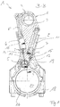
- einen Teilquerschnitt B-B eines erfindungsgemäßen Pleuels für eine Brennkraftmaschine mit variabler Verdichtung eines Kraftfahrzeugs mit zwei Ausführungsbeispielen von Rückschlagventilen in schematischer Darstellung in der Stellung für niedrige Verdichtung (ε-low);a partial cross section BB of a connecting rod according to the invention for an internal combustion engine with variable compression of a motor vehicle with two embodiments of check valves in a schematic representation in the position for low compression (ε-low);
- Fig. 2Fig. 2
-
einen vergrößerten Ausschnitt des Schnittes C-C des Pleuels gemäß
Fig. 1 ;an enlarged section of the section CC of the connecting rod according toFig. 1 ; - Fig. 3Fig. 3
-
einen vergrößerten Ausschnitt Z des Teilquerschnitts B-B des Pleuels gemäß
Fig. 1 ;an enlarged section Z of the partial cross section BB of the connecting rod according toFig. 1 ; - Fig. 4Fig. 4
-
einen vergrößerten Ausschnitt X des Teilquerschnitts B-B des Pleuels gemäß
Fig. 1 ;an enlarged section X of the partial cross section BB of the connecting rod according toFig. 1 ; - Fig. 5Fig. 5
-
eine Unteransicht des Pleuels gemäß
Fig. 1 ;a bottom view of the connecting rod according toFig. 1 ; - Fig. 6Fig. 6
-
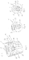
ein Einlegeelement einer Rückschlagventilausführung in perspektivischer Darstellung des Pleuels gemäß
Fig. 1 ;an insert element of a check valve execution in perspective view of the connecting rod according toFig. 1 ; - Fig. 7Fig. 7
-
einen vergrößerten Ausschnitt W des Teilquerschnitts B-B des Pleuels gemäß
Fig. 1 ;an enlarged section W of the partial cross section BB of the connecting rod according toFig. 1 ; - Fig. 8Fig. 8
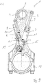
- eine Unteransicht eines erfindungsgemäßen Pleuels für eine Brennkraftmaschine mit variabler Verdichtung eines Kraftfahrzeugs mit zwei Ausführungsbeispielen von Rückschlagventilen in schematischer Darstellung in der Stellung für hohe Verdichtung (ε-high);a bottom view of a connecting rod according to the invention for a variable compression internal combustion engine of a motor vehicle with two embodiments of check valves in a schematic representation in the position for high compression (ε-high);
- Fig. 9Fig. 9
-
einen Teilquerschnitt B-B des erfindungsgemäßen Pleuels gemäß
Fig. 8 ;a partial cross section BB of the connecting rod according to the invention according toFig. 8 ; - Fig. 10Fig. 10
-
einen vergrößerten Ausschnitt des Schnittes C-C des Pleuels gemäß
Fig. 8 und9 ;an enlarged section of the section CC of the connecting rod according toFig. 8 and9 ; - Fig. 11Fig. 11
-
einen vergrößerten Ausschnitt Z des Teilquerschnitts B-B des Pleuels gemäß
Fig. 8 und9 ;an enlarged section Z of the partial cross section BB of the connecting rod according toFig. 8 and9 ; - Fig. 12Fig. 12
-
einen vergrößerten Ausschnitt X des Teilquerschnitts B-B des Pleuels gemäß
Fig. 8 und9 ;an enlarged section X of the partial cross section BB of the connecting rod according toFig. 8 and9 ; - Fig. 13Fig. 13
-
ein Schließkörper einer Rückschlagventilausführung des Pleuels gemäß
Fig. 8 und9 in perspektivischer Darstellung unda closing body of a check valve design of the connecting rod according toFig. 8 and9 in perspective and - Fig. 14Fig. 14
-
einen vergrößerten Ausschnitt W des Teilquerschnitts B-B des Pleuels gemäß
Fig. 8 und9 .an enlarged section W of the partial cross section BB of the connecting rod according toFig. 8 and9 ,
In den Figuren sind gleiche oder gleichartige Komponenten mit gleichen Bezugszeichen beziffert. Die Figuren zeigen lediglich Beispiele und sind nicht beschränkend zu verstehen.In the figures, the same or similar components are numbered with the same reference numerals. The figures are merely examples and are not intended to be limiting.
Eine Verdrehung der verstellbaren Exzenter-Verstelleinrichtung 2 wird durch Einwirken von Massen- und Lastkräften der Brennkraftmaschine initiiert, die bei einem Arbeitstakt der Brennkraftmaschine auf die Exzenter-Verstelleinrichtung 2 wirken. Während eines Arbeitstaktes verändern sich die Wirkungsrichtungen der auf die Exzenter-Verstelleinrichtung 2 wirkenden Kräfte kontinuierlich. Die Drehbewegung oder Verstellbewegung wird durch einen mit Hydraulikfluid, insbesondere mit Motoröl, beaufschlagten, im Pleuel 1 integrierten Kolben 6, 7 unterstützt, bzw. die Kolben 6, 7 verhindern ein Rückstellen der Exzenter-Verstelleinrichtung 2 aufgrund variierender Kraftwirkungsrichtungen der auf die Exzenter-Verstelleinrichtung 2 wirkenden Kräfte.A rotation of the adjustable
Die Kolben 6, 7 sind mittels Exzenterstangen 8, 9 beidseitig mit dem Exzenterhebel 3 der Exzenter-Verstelleinrichtung 2 wirkverbunden. Die Kolben 6, 7 sind in Hydraulikkammern 10, 11 verschiebbar angeordnet und über Hydraulikfluidleitungen 12, 13 mit Hydraulikfluid über Rückschlagventile 14, 15 beaufschlagt.The
Die Hydraulikfluidleitungen 12, 13 sind mit dem Umschaltventil 5 verbunden, welches über wenigstens eine nicht dargestellte Hydraulikfluidleitung mit einer Lagerschale 16 eines Hublagerauges 17 des Pleuels 1 bzw. einem Tank verbunden ist.The
Vorteilhaft kann der Pleuel 1 so ausgebildet sein, dass die Bewegungsrichtung der Kolben 6, 7 in Verlängerung von Längsachsen der Hydraulikkammern 10, 11 erfolgt, um so einen möglichst großen Kolbenhub erreichen zu können. Damit kann der Betrieb der Exzenter-Verstelleinrichtung 2 möglichst effizient ausgeführt werden.Advantageously, the connecting
Die Rückschlagventile 14, 15 verhindern dabei ein Rückfließen des Hydraulikfluids aus den Hydraulikkammern 10, 11 zurück in die Hydraulikfluidleitungen 12, 13 und ermöglichen ein Nachsaugen von Hydraulikfluid in die Hydraulikkammern 10, 11.In this case, the
Der Aufbau des beschriebenen Pleuels 1 ist nur beispielhaft dargestellt. So ist es beispielsweise möglich, das Umschaltventil 5 im Bereich eines Pleueldeckels 18 anzuordnen. Das Umschaltventil 5 kann als Hydraulikventil oder alternativ als mechanisch betätigbares Ventil ausgebildet sein. Ferner können die Hydraulikfluidleitungen abweichend von der dargestellten Ausführung vorgesehen sein. Grundsätzlich ist es auch denkbar, die Exzenter-Verstelleinrichtung 2 nur mit einer einzigen Hydraulikkammer und einem einzigen, doppelwirkenden Kolben auszubilden.The structure of the connecting
Die Rückschlagventile 14, 15 sind in den
Eine erste Ausführung des ersten Rückschlagventils 14 ist den
Das Schließelement 20 des ersten Rückschlagventils 14 ist als Kugel ausgebildet, welche wie üblich aus Metall gefertigt ist. Ebenso ist ein Keramik-Schließelement auf Grund des niedrigen Gewichts und der hohen Verschleißfestigkeit vorteilhaft denkbar. Der Ventilsitz 21 ist als konkav ausgebildeter Boden 31 der Bohrung 22 vorgesehen, so dass dieser gleichzeitig mit der Bohrung 22 hergestellt werden kann. Die konkave, umlaufende Form des Ventilsitzes 21 kann beispielsweise in einfacher Weise mittels einer 90°-Bohrerspitze in den Pleuelkörper 19 eingebracht werden.The closing
Um ein Durchströmen des Rückschlagventils 14 zu gewährleisten, weist die Kugel als Schließelement 20 einen geringeren Durchmesser als die Bohrung 22 auf, so dass zwischen dem Schließelement 20 und der Bohrung 22 ein bestimmtes Spiel vorgesehen ist.In order to ensure a flow through the
Weiter ist ein Hubbegrenzungsmittel 23 in Form eines Zylinderstiftes in dem Pleuelkörper 19 angeordnet, welches den Hub des Schließelementes 20 innerhalb der Bohrung 22 begrenzt, so dass ein Herausfallen des Schließelementes 20 verhindert und gleichzeitig ein schnelles Schließen des Rückschlagventils 14 sichergestellt werden können. Der Zylinderstift ist dabei in eine Querbohrung 24 eingepresst vorgesehen, welche die Bohrung 22 durchragt.
Das Hubbegrenzungsmittel 23 ist vorzugsweise als Zylinderstift ausgebildet, welcher als Standardbauteil besonders kostengünstig ist. Denkbar sind jedoch auch andere Bauteile, welche den Hub begrenzen.Further, a
The
Die in den
Als Hubbegrenzungsmittel 23 ist hier ebenso ein eingepresster Zylinderstift vorgesehen, welcher auch gleichzeitig das Einlegeelement 25 in der Bohrung 22 sichert. Der Ventilsitz 21 ist ebenfalls konkav am Boden 27 der Bohrung 22 ausgebildet. Im Unterschied zur ersten Ausführung des Rückschlagventils 14 weist der Boden 27 zusätzlich einen Absatz zum Festlegen des Einlegelementes 25 auf, welcher in den konkaven, umlaufenden Ventilsitz 21 für die Kugel übergeht.The in the
As
Den
Wie insbesondere
In particular
Claims (10)
Applications Claiming Priority (1)
| Application Number | Priority Date | Filing Date | Title |
|---|---|---|---|
| DE102017110446.1A DE102017110446A1 (en) | 2017-05-15 | 2017-05-15 | Connecting rod for a variable compression internal combustion engine |
Publications (2)
| Publication Number | Publication Date |
|---|---|
| EP3404232A1 true EP3404232A1 (en) | 2018-11-21 |
| EP3404232B1 EP3404232B1 (en) | 2019-11-13 |
Family
ID=62046728
Family Applications (1)
| Application Number | Title | Priority Date | Filing Date |
|---|---|---|---|
| EP18168723.7A Revoked EP3404232B1 (en) | 2017-05-15 | 2018-04-23 | Connecting rod for a combustion engine with variable compression |
Country Status (4)
| Country | Link |
|---|---|
| US (1) | US10801402B2 (en) |
| EP (1) | EP3404232B1 (en) |
| CN (1) | CN108869028A (en) |
| DE (1) | DE102017110446A1 (en) |
Cited By (1)
| Publication number | Priority date | Publication date | Assignee | Title |
|---|---|---|---|---|
| EP3404232B1 (en) | 2017-05-15 | 2019-11-13 | ECO Holding 1 GmbH | Connecting rod for a combustion engine with variable compression |
Families Citing this family (1)
| Publication number | Priority date | Publication date | Assignee | Title |
|---|---|---|---|---|
| DE102018115727B3 (en) * | 2018-06-29 | 2019-11-07 | Dr. Ing. H.C. F. Porsche Aktiengesellschaft | Supporting arrangement for an eccentric member of an adjustment arrangement and adjusting arrangement |
Citations (6)
| Publication number | Priority date | Publication date | Assignee | Title |
|---|---|---|---|---|
| DE102012112481A1 (en) | 2012-12-18 | 2014-06-18 | Dr. Ing. H.C. F. Porsche Aktiengesellschaft | Check valve for connecting rod of engine, has valve closing body, which is movable to and fro for showing valve seat along valve longitudinal axis, where radial inlet-or flow direction is provided in relation to valve longitudinal axis |
| DE102012112461A1 (en) | 2012-12-18 | 2014-06-18 | Dr. Ing. H.C. F. Porsche Aktiengesellschaft | Reversing valve for controlling engine oil of internal combustion engine i.e. petrol engine, in motor car, has groove connecting first and second hydraulic fluid lines to vent channel in first and second switch positions, respectively |
| WO2016127985A1 (en) * | 2015-02-12 | 2016-08-18 | Schaeffler Technologies AG & Co. KG | Directional control valve |
| DE102015103205A1 (en) * | 2015-03-05 | 2016-09-08 | Dr. Ing. H.C. F. Porsche Aktiengesellschaft | Connecting rod and internal combustion engine |
| DE102015213286A1 (en) * | 2015-07-15 | 2017-01-19 | Schaeffler Technologies AG & Co. KG | Support cylinder of a device for varying the compression ratio of a cylinder unit of a reciprocating internal combustion engine |
| DE102016104958A1 (en) * | 2015-11-04 | 2017-05-04 | Hilite Germany Gmbh | Check valve for a connecting rod for a variable compression internal combustion engine and connecting rod with a check valve |
Family Cites Families (31)
| Publication number | Priority date | Publication date | Assignee | Title |
|---|---|---|---|---|
| US4124002A (en) | 1976-07-23 | 1978-11-07 | Crise George W | Pressure-responsive variable length connecting rod |
| DE2747843C3 (en) * | 1977-10-26 | 1980-07-03 | Woma Apparatebau Wolfgang Maasberg & Co Gmbh, 4100 Duisburg | Piston pump, especially high-pressure piston pump in horizontal design |
| DE3511820A1 (en) * | 1985-03-30 | 1986-10-02 | Robert Bosch Gmbh, 7000 Stuttgart | VALVE CONTROL DEVICE FOR A PISTON PISTON INTERNAL COMBUSTION ENGINE |
| DE19530191A1 (en) | 1995-08-17 | 1997-02-20 | Daimler Benz Ag | connecting rod |
| DE19835146A1 (en) | 1998-08-04 | 1999-06-10 | Daimler Chrysler Ag | Automotive engine connecting rod |
| AU2001277146A1 (en) | 2000-08-02 | 2002-02-13 | Jerry I. Yadegar | Hydraulically adjustable connecting rod for internal combustion engine efficiency |
| US6619316B2 (en) | 2001-12-20 | 2003-09-16 | Ingersoll-Rand Company | Check valve having adjustable lift, packing assembly, and retrofit kit for same |
| EP1803937B1 (en) | 2002-10-09 | 2008-12-03 | Tacmina Corporation | Reciprocating diaphragm pump and check valve |
| US7458392B2 (en) | 2005-09-13 | 2008-12-02 | R. Conrader Company | Spring actuated check valve |
| DE102008001206A1 (en) | 2008-04-16 | 2009-11-05 | Horst Prof. Dr. Gentsch | connecting rod |
| JP4606509B2 (en) | 2009-03-06 | 2011-01-05 | 力 小高 | Internal combustion engine and connecting rod for internal combustion engine |
| US8312889B2 (en) | 2009-06-30 | 2012-11-20 | Snyder Industries, Inc. | Combination flow control valve and reverse flow check valve |
| ITMI20100974A1 (en) | 2010-05-28 | 2011-11-29 | Debem S R L | METHOD FOR FORMING A BALL STOP IN CHECK VALVES AND SIMILAR APPLICATIONS |
| AU2012299891A1 (en) * | 2011-07-01 | 2014-02-20 | Nvb Composites International Uk Ltd | Piston-chamber combination - Vanderblom Motor |
| AT511803B1 (en) | 2011-12-23 | 2013-03-15 | Avl List Gmbh | CONNECTING ROD FOR A PUSH-PISTON MACHINE |
| AT513054B1 (en) | 2012-07-03 | 2014-09-15 | Avl List Gmbh | Length adjustable connecting rod |
| US9670806B2 (en) * | 2012-09-07 | 2017-06-06 | Miniature Precision Components, Inc. | Turbo PCV valve |
| GEP20156290B (en) | 2013-05-22 | 2015-05-25 | Internal combustion engine connecting rod | |
| US9322361B2 (en) * | 2013-08-07 | 2016-04-26 | Cummins Inc. | Gaseous fuel mixer for internal combustion engine |
| DE102013014090A1 (en) * | 2013-08-27 | 2015-03-05 | Dr. Ing. H.C. F. Porsche Ag | Internal combustion engine and connecting rod |
| AT514071B1 (en) | 2013-10-18 | 2014-10-15 | Avl List Gmbh | Length adjustable connecting rod |
| DE102013021065A1 (en) * | 2013-12-18 | 2015-06-18 | Fev Gmbh | Piston machine with support piston |
| DE112015005354A5 (en) | 2014-11-27 | 2017-08-03 | Fev Gmbh | Internal combustion engine with adjustable compression ratio and connecting rod for such an internal combustion engine |
| JP6070683B2 (en) * | 2014-12-22 | 2017-02-01 | トヨタ自動車株式会社 | Variable length connecting rod and variable compression ratio internal combustion engine |
| KR20180018663A (en) | 2015-06-18 | 2018-02-21 | 아베엘 리스트 게엠베하 | Length-adjustable connecting rod |
| AT517217B1 (en) | 2015-06-18 | 2016-12-15 | Avl List Gmbh | LENGTH-ADJUSTABLE CONNECTING ROD |
| DE102016215281A1 (en) | 2015-08-14 | 2017-02-16 | Avl List Gmbh | Length adjustable connecting rod |
| CN105275623A (en) | 2015-09-24 | 2016-01-27 | 宁波星豪汽车维修有限公司 | Variable-compression-ratio piston device |
| DE102016114976A1 (en) * | 2016-03-21 | 2017-09-21 | Hilite Germany Gmbh | Check valve for a connecting rod for a variable compression internal combustion engine and connecting rod with a check valve |
| DE102017121443A1 (en) * | 2017-02-13 | 2018-08-16 | ECO Holding 1 GmbH | Check valve for a connecting rod of an internal combustion engine with variable compression and connecting rod with such a check valve |
| DE102017110446A1 (en) | 2017-05-15 | 2018-11-15 | ECO Holding 1 GmbH | Connecting rod for a variable compression internal combustion engine |
-
2017
- 2017-05-15 DE DE102017110446.1A patent/DE102017110446A1/en active Pending
-
2018
- 2018-04-23 EP EP18168723.7A patent/EP3404232B1/en not_active Revoked
- 2018-05-08 CN CN201810431845.4A patent/CN108869028A/en active Pending
- 2018-05-15 US US15/979,805 patent/US10801402B2/en active Active
Patent Citations (6)
| Publication number | Priority date | Publication date | Assignee | Title |
|---|---|---|---|---|
| DE102012112481A1 (en) | 2012-12-18 | 2014-06-18 | Dr. Ing. H.C. F. Porsche Aktiengesellschaft | Check valve for connecting rod of engine, has valve closing body, which is movable to and fro for showing valve seat along valve longitudinal axis, where radial inlet-or flow direction is provided in relation to valve longitudinal axis |
| DE102012112461A1 (en) | 2012-12-18 | 2014-06-18 | Dr. Ing. H.C. F. Porsche Aktiengesellschaft | Reversing valve for controlling engine oil of internal combustion engine i.e. petrol engine, in motor car, has groove connecting first and second hydraulic fluid lines to vent channel in first and second switch positions, respectively |
| WO2016127985A1 (en) * | 2015-02-12 | 2016-08-18 | Schaeffler Technologies AG & Co. KG | Directional control valve |
| DE102015103205A1 (en) * | 2015-03-05 | 2016-09-08 | Dr. Ing. H.C. F. Porsche Aktiengesellschaft | Connecting rod and internal combustion engine |
| DE102015213286A1 (en) * | 2015-07-15 | 2017-01-19 | Schaeffler Technologies AG & Co. KG | Support cylinder of a device for varying the compression ratio of a cylinder unit of a reciprocating internal combustion engine |
| DE102016104958A1 (en) * | 2015-11-04 | 2017-05-04 | Hilite Germany Gmbh | Check valve for a connecting rod for a variable compression internal combustion engine and connecting rod with a check valve |
Cited By (1)
| Publication number | Priority date | Publication date | Assignee | Title |
|---|---|---|---|---|
| EP3404232B1 (en) | 2017-05-15 | 2019-11-13 | ECO Holding 1 GmbH | Connecting rod for a combustion engine with variable compression |
Also Published As
| Publication number | Publication date |
|---|---|
| US10801402B2 (en) | 2020-10-13 |
| CN108869028A (en) | 2018-11-23 |
| EP3404232B1 (en) | 2019-11-13 |
| US20180328276A1 (en) | 2018-11-15 |
| DE102017110446A1 (en) | 2018-11-15 |
Similar Documents
| Publication | Publication Date | Title |
|---|---|---|
| DE102014106715A1 (en) | Changeover valve and internal combustion engine | |
| DE102009057070A1 (en) | Piston machine for use as a vacuum pump for medical purposes | |
| DE102017121443A1 (en) | Check valve for a connecting rod of an internal combustion engine with variable compression and connecting rod with such a check valve | |
| DE102015110664A1 (en) | Changeover valve and internal combustion engine | |
| EP3404232B1 (en) | Connecting rod for a combustion engine with variable compression | |
| WO2017207255A1 (en) | Switchover valve for controlling a hydraulic fluid flow, and connecting rod for a variable-compression internal combustion engine having a switchover valve | |
| DE102016110279A1 (en) | Check valve for a connecting rod for variable compression of an internal combustion engine and connecting rod with such a check valve | |
| EP3219954B1 (en) | Switching valve for controlling a hydraulic liquid stream and connecting rod with a switching valve | |
| DE102018107108A1 (en) | Switching valve for controlling a hydraulic fluid flow and connecting rod for a variable compression internal combustion engine with a switching valve | |
| EP3361069B1 (en) | Connecting rod of a combustion engine with variable compression with a check valve | |
| DE102017106939A1 (en) | Connecting rod for a variable compression internal combustion engine and a check valve for a connecting rod for a variable compression internal combustion engine | |
| DE102017107673A1 (en) | Connecting rod for a variable compression of an internal combustion engine | |
| EP3502436B1 (en) | Connecting rod for a combustion engine with variable compression with a switching valve | |
| DE102017107719A1 (en) | Hydraulic valve for adjusting a hydraulic fluid flow of a connecting rod for a variable compression internal combustion engine | |
| DE102015121918A1 (en) | Changeover valve, connecting rod and internal combustion engine | |
| DE102016117874A1 (en) | Changeover valve for controlling a hydraulic fluid flow and connecting rod with a changeover valve | |
| DE102016104958A1 (en) | Check valve for a connecting rod for a variable compression internal combustion engine and connecting rod with a check valve | |
| EP3085921A1 (en) | Switching valve and connecting rod with same | |
| DE102015121917B4 (en) | Changeover valve, connecting rod and internal combustion engine | |
| EP3173601B1 (en) | Non-return valve for a connecting rod for a variable compression of an internal combustion engine, and connecting rod with such a non-return valve | |
| WO2017153192A1 (en) | Switchover valve for controlling a hydraulic fluid flow, and connecting rod for an internal combustion engine with variable compression and a switchover valve | |
| WO2017102470A1 (en) | Connecting rod for variable compression of an internal combustion engine | |
| DE102015015884A1 (en) | Piston arrangement for a variable compression ratio having combustion chamber of an internal combustion engine | |
| DE102016123635A1 (en) | Connecting rod for a variable compression internal combustion engine | |
| DE102020109088A1 (en) | Connecting rod for an internal combustion engine with variable compression with a switching valve |
Legal Events
| Date | Code | Title | Description |
|---|---|---|---|
| PUAI | Public reference made under article 153(3) epc to a published international application that has entered the european phase |
Free format text: ORIGINAL CODE: 0009012 |
|
| STAA | Information on the status of an ep patent application or granted ep patent |
Free format text: STATUS: THE APPLICATION HAS BEEN PUBLISHED |
|
| AK | Designated contracting states |
Kind code of ref document: A1 Designated state(s): AL AT BE BG CH CY CZ DE DK EE ES FI FR GB GR HR HU IE IS IT LI LT LU LV MC MK MT NL NO PL PT RO RS SE SI SK SM TR |
|
| AX | Request for extension of the european patent |
Extension state: BA ME |
|
| STAA | Information on the status of an ep patent application or granted ep patent |
Free format text: STATUS: REQUEST FOR EXAMINATION WAS MADE |
|
| 17P | Request for examination filed |
Effective date: 20181212 |
|
| RBV | Designated contracting states (corrected) |
Designated state(s): AL AT BE BG CH CY CZ DE DK EE ES FI FR GB GR HR HU IE IS IT LI LT LU LV MC MK MT NL NO PL PT RO RS SE SI SK SM TR |
|
| RIC1 | Information provided on ipc code assigned before grant |
Ipc: F16K 15/02 20060101ALI20190606BHEP Ipc: F16C 7/06 20060101ALI20190606BHEP Ipc: F02B 75/04 20060101AFI20190606BHEP |
|
| GRAP | Despatch of communication of intention to grant a patent |
Free format text: ORIGINAL CODE: EPIDOSNIGR1 |
|
| STAA | Information on the status of an ep patent application or granted ep patent |
Free format text: STATUS: GRANT OF PATENT IS INTENDED |
|
| GRAS | Grant fee paid |
Free format text: ORIGINAL CODE: EPIDOSNIGR3 |
|
| INTG | Intention to grant announced |
Effective date: 20190801 |
|
| GRAA | (expected) grant |
Free format text: ORIGINAL CODE: 0009210 |
|
| STAA | Information on the status of an ep patent application or granted ep patent |
Free format text: STATUS: THE PATENT HAS BEEN GRANTED |
|
| AK | Designated contracting states |
Kind code of ref document: B1 Designated state(s): AL AT BE BG CH CY CZ DE DK EE ES FI FR GB GR HR HU IE IS IT LI LT LU LV MC MK MT NL NO PL PT RO RS SE SI SK SM TR |
|
| REG | Reference to a national code |
Ref country code: CH Ref legal event code: EP Ref country code: AT Ref legal event code: REF Ref document number: 1201886 Country of ref document: AT Kind code of ref document: T Effective date: 20191115 |
|
| REG | Reference to a national code |
Ref country code: DE Ref legal event code: R096 Ref document number: 502018000358 Country of ref document: DE |
|
| REG | Reference to a national code |
Ref country code: IE Ref legal event code: FG4D Free format text: LANGUAGE OF EP DOCUMENT: GERMAN |
|
| REG | Reference to a national code |
Ref country code: NL Ref legal event code: MP Effective date: 20191113 |
|
| REG | Reference to a national code |
Ref country code: LT Ref legal event code: MG4D |
|
| PG25 | Lapsed in a contracting state [announced via postgrant information from national office to epo] |
Ref country code: NL Free format text: LAPSE BECAUSE OF FAILURE TO SUBMIT A TRANSLATION OF THE DESCRIPTION OR TO PAY THE FEE WITHIN THE PRESCRIBED TIME-LIMIT Effective date: 20191113 Ref country code: PL Free format text: LAPSE BECAUSE OF FAILURE TO SUBMIT A TRANSLATION OF THE DESCRIPTION OR TO PAY THE FEE WITHIN THE PRESCRIBED TIME-LIMIT Effective date: 20191113 Ref country code: LT Free format text: LAPSE BECAUSE OF FAILURE TO SUBMIT A TRANSLATION OF THE DESCRIPTION OR TO PAY THE FEE WITHIN THE PRESCRIBED TIME-LIMIT Effective date: 20191113 Ref country code: GR Free format text: LAPSE BECAUSE OF FAILURE TO SUBMIT A TRANSLATION OF THE DESCRIPTION OR TO PAY THE FEE WITHIN THE PRESCRIBED TIME-LIMIT Effective date: 20200214 Ref country code: NO Free format text: LAPSE BECAUSE OF FAILURE TO SUBMIT A TRANSLATION OF THE DESCRIPTION OR TO PAY THE FEE WITHIN THE PRESCRIBED TIME-LIMIT Effective date: 20200213 Ref country code: BG Free format text: LAPSE BECAUSE OF FAILURE TO SUBMIT A TRANSLATION OF THE DESCRIPTION OR TO PAY THE FEE WITHIN THE PRESCRIBED TIME-LIMIT Effective date: 20200213 Ref country code: FI Free format text: LAPSE BECAUSE OF FAILURE TO SUBMIT A TRANSLATION OF THE DESCRIPTION OR TO PAY THE FEE WITHIN THE PRESCRIBED TIME-LIMIT Effective date: 20191113 Ref country code: PT Free format text: LAPSE BECAUSE OF FAILURE TO SUBMIT A TRANSLATION OF THE DESCRIPTION OR TO PAY THE FEE WITHIN THE PRESCRIBED TIME-LIMIT Effective date: 20200313 Ref country code: LV Free format text: LAPSE BECAUSE OF FAILURE TO SUBMIT A TRANSLATION OF THE DESCRIPTION OR TO PAY THE FEE WITHIN THE PRESCRIBED TIME-LIMIT Effective date: 20191113 Ref country code: SE Free format text: LAPSE BECAUSE OF FAILURE TO SUBMIT A TRANSLATION OF THE DESCRIPTION OR TO PAY THE FEE WITHIN THE PRESCRIBED TIME-LIMIT Effective date: 20191113 |
|
| PG25 | Lapsed in a contracting state [announced via postgrant information from national office to epo] |
Ref country code: HR Free format text: LAPSE BECAUSE OF FAILURE TO SUBMIT A TRANSLATION OF THE DESCRIPTION OR TO PAY THE FEE WITHIN THE PRESCRIBED TIME-LIMIT Effective date: 20191113 Ref country code: IS Free format text: LAPSE BECAUSE OF FAILURE TO SUBMIT A TRANSLATION OF THE DESCRIPTION OR TO PAY THE FEE WITHIN THE PRESCRIBED TIME-LIMIT Effective date: 20200313 Ref country code: RS Free format text: LAPSE BECAUSE OF FAILURE TO SUBMIT A TRANSLATION OF THE DESCRIPTION OR TO PAY THE FEE WITHIN THE PRESCRIBED TIME-LIMIT Effective date: 20191113 |
|
| PG25 | Lapsed in a contracting state [announced via postgrant information from national office to epo] |
Ref country code: AL Free format text: LAPSE BECAUSE OF FAILURE TO SUBMIT A TRANSLATION OF THE DESCRIPTION OR TO PAY THE FEE WITHIN THE PRESCRIBED TIME-LIMIT Effective date: 20191113 |
|
| PG25 | Lapsed in a contracting state [announced via postgrant information from national office to epo] |
Ref country code: CZ Free format text: LAPSE BECAUSE OF FAILURE TO SUBMIT A TRANSLATION OF THE DESCRIPTION OR TO PAY THE FEE WITHIN THE PRESCRIBED TIME-LIMIT Effective date: 20191113 Ref country code: RO Free format text: LAPSE BECAUSE OF FAILURE TO SUBMIT A TRANSLATION OF THE DESCRIPTION OR TO PAY THE FEE WITHIN THE PRESCRIBED TIME-LIMIT Effective date: 20191113 Ref country code: DK Free format text: LAPSE BECAUSE OF FAILURE TO SUBMIT A TRANSLATION OF THE DESCRIPTION OR TO PAY THE FEE WITHIN THE PRESCRIBED TIME-LIMIT Effective date: 20191113 Ref country code: ES Free format text: LAPSE BECAUSE OF FAILURE TO SUBMIT A TRANSLATION OF THE DESCRIPTION OR TO PAY THE FEE WITHIN THE PRESCRIBED TIME-LIMIT Effective date: 20191113 Ref country code: EE Free format text: LAPSE BECAUSE OF FAILURE TO SUBMIT A TRANSLATION OF THE DESCRIPTION OR TO PAY THE FEE WITHIN THE PRESCRIBED TIME-LIMIT Effective date: 20191113 |
|
| PGFP | Annual fee paid to national office [announced via postgrant information from national office to epo] |
Ref country code: FR Payment date: 20200420 Year of fee payment: 3 Ref country code: DE Payment date: 20200420 Year of fee payment: 3 |
|
| REG | Reference to a national code |
Ref country code: DE Ref legal event code: R026 Ref document number: 502018000358 Country of ref document: DE |
|
| PLBI | Opposition filed |
Free format text: ORIGINAL CODE: 0009260 |
|
| PG25 | Lapsed in a contracting state [announced via postgrant information from national office to epo] |
Ref country code: SK Free format text: LAPSE BECAUSE OF FAILURE TO SUBMIT A TRANSLATION OF THE DESCRIPTION OR TO PAY THE FEE WITHIN THE PRESCRIBED TIME-LIMIT Effective date: 20191113 Ref country code: SM Free format text: LAPSE BECAUSE OF FAILURE TO SUBMIT A TRANSLATION OF THE DESCRIPTION OR TO PAY THE FEE WITHIN THE PRESCRIBED TIME-LIMIT Effective date: 20191113 |
|
| PLAX | Notice of opposition and request to file observation + time limit sent |
Free format text: ORIGINAL CODE: EPIDOSNOBS2 |
|
| 26 | Opposition filed |
Opponent name: AVL LIST GMBH Effective date: 20200812 |
|
| PG25 | Lapsed in a contracting state [announced via postgrant information from national office to epo] |
Ref country code: MC Free format text: LAPSE BECAUSE OF FAILURE TO SUBMIT A TRANSLATION OF THE DESCRIPTION OR TO PAY THE FEE WITHIN THE PRESCRIBED TIME-LIMIT Effective date: 20191113 Ref country code: SI Free format text: LAPSE BECAUSE OF FAILURE TO SUBMIT A TRANSLATION OF THE DESCRIPTION OR TO PAY THE FEE WITHIN THE PRESCRIBED TIME-LIMIT Effective date: 20191113 |
|
| RDAF | Communication despatched that patent is revoked |
Free format text: ORIGINAL CODE: EPIDOSNREV1 |
|
| REG | Reference to a national code |
Ref country code: DE Ref legal event code: R064 Ref document number: 502018000358 Country of ref document: DE Ref country code: DE Ref legal event code: R103 Ref document number: 502018000358 Country of ref document: DE |
|
| PG25 | Lapsed in a contracting state [announced via postgrant information from national office to epo] |
Ref country code: LU Free format text: LAPSE BECAUSE OF NON-PAYMENT OF DUE FEES Effective date: 20200423 Ref country code: IT Free format text: LAPSE BECAUSE OF FAILURE TO SUBMIT A TRANSLATION OF THE DESCRIPTION OR TO PAY THE FEE WITHIN THE PRESCRIBED TIME-LIMIT Effective date: 20191113 |
|
| REG | Reference to a national code |
Ref country code: BE Ref legal event code: MM Effective date: 20200430 |
|
| PG25 | Lapsed in a contracting state [announced via postgrant information from national office to epo] |
Ref country code: BE Free format text: LAPSE BECAUSE OF NON-PAYMENT OF DUE FEES Effective date: 20200430 |
|
| RDAG | Patent revoked |
Free format text: ORIGINAL CODE: 0009271 |
|
| STAA | Information on the status of an ep patent application or granted ep patent |
Free format text: STATUS: PATENT REVOKED |
|
| PG25 | Lapsed in a contracting state [announced via postgrant information from national office to epo] |
Ref country code: IE Free format text: LAPSE BECAUSE OF NON-PAYMENT OF DUE FEES Effective date: 20200423 |
|
| REG | Reference to a national code |
Ref country code: CH Ref legal event code: PL |
|
| REG | Reference to a national code |
Ref country code: FI Ref legal event code: MGE |
|
| 27W | Patent revoked |
Effective date: 20210121 |
|
| GBPR | Gb: patent revoked under art. 102 of the ep convention designating the uk as contracting state |
Effective date: 20210121 |
|
| REG | Reference to a national code |
Ref country code: AT Ref legal event code: MA03 Ref document number: 1201886 Country of ref document: AT Kind code of ref document: T Effective date: 20210121 |
|
| PG25 | Lapsed in a contracting state [announced via postgrant information from national office to epo] |
Ref country code: TR Free format text: LAPSE BECAUSE OF FAILURE TO SUBMIT A TRANSLATION OF THE DESCRIPTION OR TO PAY THE FEE WITHIN THE PRESCRIBED TIME-LIMIT Effective date: 20191113 |
|
| PG25 | Lapsed in a contracting state [announced via postgrant information from national office to epo] |
Ref country code: MK Free format text: LAPSE BECAUSE OF FAILURE TO SUBMIT A TRANSLATION OF THE DESCRIPTION OR TO PAY THE FEE WITHIN THE PRESCRIBED TIME-LIMIT Effective date: 20191113 |