EP3404231A1 - Turbocharger - Google Patents
Turbocharger Download PDFInfo
- Publication number
- EP3404231A1 EP3404231A1 EP16892587.3A EP16892587A EP3404231A1 EP 3404231 A1 EP3404231 A1 EP 3404231A1 EP 16892587 A EP16892587 A EP 16892587A EP 3404231 A1 EP3404231 A1 EP 3404231A1
- Authority
- EP
- European Patent Office
- Prior art keywords
- heat shielding
- turbine
- nozzle
- bearing housing
- housing
- Prior art date
- Legal status (The legal status is an assumption and is not a legal conclusion. Google has not performed a legal analysis and makes no representation as to the accuracy of the status listed.)
- Granted
Links
- 239000000463 material Substances 0.000 claims description 96
- 230000002093 peripheral effect Effects 0.000 claims description 67
- 230000004308 accommodation Effects 0.000 claims description 31
- 239000011810 insulating material Substances 0.000 description 10
- 230000004048 modification Effects 0.000 description 7
- 238000012986 modification Methods 0.000 description 7
- VYPSYNLAJGMNEJ-UHFFFAOYSA-N Silicium dioxide Chemical compound O=[Si]=O VYPSYNLAJGMNEJ-UHFFFAOYSA-N 0.000 description 6
- 229910010293 ceramic material Inorganic materials 0.000 description 3
- 239000011248 coating agent Substances 0.000 description 3
- 238000000576 coating method Methods 0.000 description 3
- 239000002184 metal Substances 0.000 description 3
- 239000000377 silicon dioxide Substances 0.000 description 3
- 238000001816 cooling Methods 0.000 description 2
- 238000005461 lubrication Methods 0.000 description 2
- 230000001902 propagating effect Effects 0.000 description 2
- 230000000994 depressogenic effect Effects 0.000 description 1
- 230000000694 effects Effects 0.000 description 1
- 229910001026 inconel Inorganic materials 0.000 description 1
- 230000000149 penetrating effect Effects 0.000 description 1
- 229910001256 stainless steel alloy Inorganic materials 0.000 description 1
Images


Classifications
-
- F—MECHANICAL ENGINEERING; LIGHTING; HEATING; WEAPONS; BLASTING
- F01—MACHINES OR ENGINES IN GENERAL; ENGINE PLANTS IN GENERAL; STEAM ENGINES
- F01D—NON-POSITIVE DISPLACEMENT MACHINES OR ENGINES, e.g. STEAM TURBINES
- F01D25/00—Component parts, details, or accessories, not provided for in, or of interest apart from, other groups
- F01D25/08—Cooling; Heating; Heat-insulation
- F01D25/14—Casings modified therefor
- F01D25/145—Thermally insulated casings
-
- F—MECHANICAL ENGINEERING; LIGHTING; HEATING; WEAPONS; BLASTING
- F01—MACHINES OR ENGINES IN GENERAL; ENGINE PLANTS IN GENERAL; STEAM ENGINES
- F01D—NON-POSITIVE DISPLACEMENT MACHINES OR ENGINES, e.g. STEAM TURBINES
- F01D17/00—Regulating or controlling by varying flow
- F01D17/10—Final actuators
- F01D17/12—Final actuators arranged in stator parts
- F01D17/14—Final actuators arranged in stator parts varying effective cross-sectional area of nozzles or guide conduits
- F01D17/16—Final actuators arranged in stator parts varying effective cross-sectional area of nozzles or guide conduits by means of nozzle vanes
- F01D17/165—Final actuators arranged in stator parts varying effective cross-sectional area of nozzles or guide conduits by means of nozzle vanes for radial flow, i.e. the vanes turning around axes which are essentially parallel to the rotor centre line
-
- F—MECHANICAL ENGINEERING; LIGHTING; HEATING; WEAPONS; BLASTING
- F01—MACHINES OR ENGINES IN GENERAL; ENGINE PLANTS IN GENERAL; STEAM ENGINES
- F01D—NON-POSITIVE DISPLACEMENT MACHINES OR ENGINES, e.g. STEAM TURBINES
- F01D25/00—Component parts, details, or accessories, not provided for in, or of interest apart from, other groups
- F01D25/16—Arrangement of bearings; Supporting or mounting bearings in casings
-
- F—MECHANICAL ENGINEERING; LIGHTING; HEATING; WEAPONS; BLASTING
- F02—COMBUSTION ENGINES; HOT-GAS OR COMBUSTION-PRODUCT ENGINE PLANTS
- F02B—INTERNAL-COMBUSTION PISTON ENGINES; COMBUSTION ENGINES IN GENERAL
- F02B37/00—Engines characterised by provision of pumps driven at least for part of the time by exhaust
- F02B37/12—Control of the pumps
- F02B37/24—Control of the pumps by using pumps or turbines with adjustable guide vanes
-
- F—MECHANICAL ENGINEERING; LIGHTING; HEATING; WEAPONS; BLASTING
- F02—COMBUSTION ENGINES; HOT-GAS OR COMBUSTION-PRODUCT ENGINE PLANTS
- F02B—INTERNAL-COMBUSTION PISTON ENGINES; COMBUSTION ENGINES IN GENERAL
- F02B39/00—Component parts, details, or accessories relating to, driven charging or scavenging pumps, not provided for in groups F02B33/00 - F02B37/00
-
- F—MECHANICAL ENGINEERING; LIGHTING; HEATING; WEAPONS; BLASTING
- F02—COMBUSTION ENGINES; HOT-GAS OR COMBUSTION-PRODUCT ENGINE PLANTS
- F02C—GAS-TURBINE PLANTS; AIR INTAKES FOR JET-PROPULSION PLANTS; CONTROLLING FUEL SUPPLY IN AIR-BREATHING JET-PROPULSION PLANTS
- F02C6/00—Plural gas-turbine plants; Combinations of gas-turbine plants with other apparatus; Adaptations of gas-turbine plants for special use
- F02C6/04—Gas-turbine plants providing heated or pressurised working fluid for other apparatus, e.g. without mechanical power output
- F02C6/10—Gas-turbine plants providing heated or pressurised working fluid for other apparatus, e.g. without mechanical power output supplying working fluid to a user, e.g. a chemical process, which returns working fluid to a turbine of the plant
- F02C6/12—Turbochargers, i.e. plants for augmenting mechanical power output of internal-combustion piston engines by increase of charge pressure
-
- F—MECHANICAL ENGINEERING; LIGHTING; HEATING; WEAPONS; BLASTING
- F05—INDEXING SCHEMES RELATING TO ENGINES OR PUMPS IN VARIOUS SUBCLASSES OF CLASSES F01-F04
- F05D—INDEXING SCHEME FOR ASPECTS RELATING TO NON-POSITIVE-DISPLACEMENT MACHINES OR ENGINES, GAS-TURBINES OR JET-PROPULSION PLANTS
- F05D2220/00—Application
- F05D2220/40—Application in turbochargers
-
- F—MECHANICAL ENGINEERING; LIGHTING; HEATING; WEAPONS; BLASTING
- F05—INDEXING SCHEMES RELATING TO ENGINES OR PUMPS IN VARIOUS SUBCLASSES OF CLASSES F01-F04
- F05D—INDEXING SCHEME FOR ASPECTS RELATING TO NON-POSITIVE-DISPLACEMENT MACHINES OR ENGINES, GAS-TURBINES OR JET-PROPULSION PLANTS
- F05D2240/00—Components
- F05D2240/10—Stators
- F05D2240/15—Heat shield
-
- F—MECHANICAL ENGINEERING; LIGHTING; HEATING; WEAPONS; BLASTING
- F05—INDEXING SCHEMES RELATING TO ENGINES OR PUMPS IN VARIOUS SUBCLASSES OF CLASSES F01-F04
- F05D—INDEXING SCHEME FOR ASPECTS RELATING TO NON-POSITIVE-DISPLACEMENT MACHINES OR ENGINES, GAS-TURBINES OR JET-PROPULSION PLANTS
- F05D2250/00—Geometry
- F05D2250/90—Variable geometry
-
- F—MECHANICAL ENGINEERING; LIGHTING; HEATING; WEAPONS; BLASTING
- F05—INDEXING SCHEMES RELATING TO ENGINES OR PUMPS IN VARIOUS SUBCLASSES OF CLASSES F01-F04
- F05D—INDEXING SCHEME FOR ASPECTS RELATING TO NON-POSITIVE-DISPLACEMENT MACHINES OR ENGINES, GAS-TURBINES OR JET-PROPULSION PLANTS
- F05D2260/00—Function
- F05D2260/20—Heat transfer, e.g. cooling
- F05D2260/231—Preventing heat transfer
-
- Y—GENERAL TAGGING OF NEW TECHNOLOGICAL DEVELOPMENTS; GENERAL TAGGING OF CROSS-SECTIONAL TECHNOLOGIES SPANNING OVER SEVERAL SECTIONS OF THE IPC; TECHNICAL SUBJECTS COVERED BY FORMER USPC CROSS-REFERENCE ART COLLECTIONS [XRACs] AND DIGESTS
- Y02—TECHNOLOGIES OR APPLICATIONS FOR MITIGATION OR ADAPTATION AGAINST CLIMATE CHANGE
- Y02T—CLIMATE CHANGE MITIGATION TECHNOLOGIES RELATED TO TRANSPORTATION
- Y02T10/00—Road transport of goods or passengers
- Y02T10/10—Internal combustion engine [ICE] based vehicles
- Y02T10/12—Improving ICE efficiencies
Definitions
- the present invention relates to a turbocharger.
- a turbocharger includes a turbocharger body, a compressor, and a turbine.
- the turbocharger body includes a rotating shaft and a bearing housing which rotatably supports the rotating shaft via a bearing.
- the rotating shaft includes a turbine wheel on a first end portion side and a compressor wheel on a second end portion side.
- the turbine wheel is accommodated in a turbine housing which is connected to the bearing housing.
- the compressor wheel is accommodated in a compressor housing which is connected to the bearing housing.
- the turbine wheel In the turbocharger, the turbine wheel is rotated by a flow of an exhaust gas supplied from an engine into the turbine housing.
- the compressor wheel provided in the compressor housing is rotated according to the rotation of the turbine wheel, and thus, air is compressed.
- the air compressed by the compressor is supplied to the engine.
- a high-temperature exhaust gas flows to the turbine, and thus, a temperature of the turbine housing increases. If thermal energy of the turbine escapes to the bearing housing side, energy loss occurs in the turbine.
- PTL 1 discloses a configuration in which a heat insulating material is interposed between a turbine housing and a bearing housing in order to suppress a heat input from a turbine to the bearing housing.
- a nozzle vane In a turbocharger in which a variable vane is included in a turbine, a nozzle vane, a disc-shaped mount plate rotatably supporting the nozzle vane, and a mechanism for changing an orientation of the nozzle vane are provided as members configuring the variable vane.
- An object of the present invention is to provide a turbocharger including a variable vane, the turbocharger being capable of suppressing energy loss in a turbine and a heat input from the turbine to a bearing.
- a turbocharger including: a rotating shaft which extends along an axis; a turbine wheel which is provided on a first end portion side of the rotating shaft; a compressor wheel which is provided on a second end portion side of the rotating shaft; and a bearing housing which rotatably supports the rotating shaft.
- the turbocharger further includes a turbine housing which accommodates the turbine wheel; and a scroll flow path which is formed in the turbine housing, is continuous in a circumferential direction to be located radially outside the turbine wheel, and allows a gas rotating the turbine wheel to flow therethrough.
- the turbocharger further includes a nozzle flow path which allows the gas to be introduced radially inward from the scroll flow path and supplies the gas to the turbine wheel; and a nozzle mount which is provided on the bearing housing side with respect to the nozzle flow path.
- the turbocharger further includes a vane which is rotatably supported by the nozzle mount and adjusts an amount of the gas introduced into the nozzle flow path; and a heat shielding portion which suppresses an increase in a quantity of heat transmitted from the turbine housing side to the bearing housing side with the nozzle mount interposed therebetween.
- the nozzle mount is interposed in the heat shielding portion to suppress an increase in the quantity of the heat transmitted from the turbine housing side to the bearing housing side, and thus, it is possible to inhibit heat on the turbine housing side from being transmitted to the bearing housing in a configuration where the nozzle flow path including the vane, of which an angle is variable, is included.
- the heat shielding portion may be a mount outer peripheral portion heat shielding material provided between an end portion radially outside the nozzle mount and at least one of the bearing housing or the turbine housing.
- the mount outer peripheral portion heat shielding material can inhibit heat on the turbine housing side from being transmitted to the bearing housing via the nozzle mount.
- a rotating mechanism rotating the vane may be provided on the bearing housing side with respect to the nozzle mount, an accommodation chamber which accommodates the rotating mechanism may be formed in the bearing housing, and the heat shielding portion may be an accommodation chamber heat shielding material provided on an inner peripheral surface of the accommodation chamber.
- the turbine housing may have a scroll formed portion that forms the scroll flow path and a connecting portion that is formed to extend from the scroll formed portion to the bearing housing side, which is an opposite side, with the nozzle mount interposed therebetween, and is connected to the bearing housing.
- the heat shielding portion may be a housing outer peripheral heat shielding material covering only the connecting portion, out of the scroll formed portion and the connecting portion, from an outer peripheral side.
- the heat shielding portion may be a mount surface heat shielding material provided in a portion of the nozzle mount, the portion facing the scroll flow path side.
- turbocharger it is possible for the turbocharger including the variable vanes to suppress the energy loss in the turbine and the heat input from the turbine to the bearing.
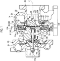
- Fig. 1 is a cross-sectional view showing an overall configuration of a turbocharger according to an embodiment of the present invention.
- a turbocharger 10A of the present embodiment includes a turbocharger body 11, a compressor 20, and a turbine 30.
- the turbocharger 10A is mounted as an auxiliary machine of an engine on an automobile or the like in a state where a rotating shaft 14 extends in a horizontal direction.
- the turbocharger 10A is supported by a vehicle body or the like via a bracket (not shown), the compressor 20, the turbine 30, or the like.
- the turbocharger body 11 includes the rotating shaft 14, a bearing 15A, and a bearing housing 16.
- the rotating shaft 14 is rotatably supported by the bearing 15A accommodated in the bearing housing 16.
- a turbine wheel 12 is integrally formed on a first end portion 14a of the rotating shaft 14, and a compressor wheel 13 is attached to a second end portion 14b of the rotating shaft 14.
- the bearing housing 16 is formed to accommodate the bearing 15A and to cover the rotating shaft 14 from the outside.
- the bearing housing 16 includes an opening 16a on a first end portion side of the bearing housing 16 and an opening 16b on a second end portion side thereof.
- the first end portion 14a and the second end portion 14b of the above-described rotating shaft 14 protrude toward the outside of the bearing housing 16 through the openings 16a and 16b, respectively. That is, each of the above-described turbine wheel 12 and the compressor wheel 13 is disposed outside the bearing housing 16.
- the compressor 20 includes the compressor wheel 13 and a compressor housing 21.
- the compressor 20 is a so-called a centrifugal compressor and boosts air such as outside air.
- the boosted air is supplied to the engine.
- the compressor wheel 13 is rotated together with the rotating shaft 14.
- the compressor wheel is rotated, and air flowing from an inlet of the compressor housing 21 is moved radially outward while being compressed and is discharged to the outside of the compressor housing 21 via a scroll or the like.
- the turbine 30 recovers energy of an exhaust gas discharged from an engine (not shown).
- the turbine 30 mainly includes the turbine wheel 12 and a turbine housing 31.
- the turbine wheel 12 converts energy of the exhaust gas into rotational energy.
- the turbine wheel 12 is accommodated in the turbine housing 31 and includes a plurality of turbine blades 12W in a circumferential direction.
- the turbine wheel 12 is rotated by the exhaust gas supplied to the inside of the turbine housing 31.
- the rotation of the turbine wheel 12 is transmitted to the compressor wheel 13 via the rotating shaft 14.
- the turbine housing 31 has an opening 31a at a position facing the bearing housing 16. An accommodation space for accommodating the turbine wheel 12 is formed inside the turbine housing 31.
- the turbine housing 31 includes a gas introduction portion (not shown), a scroll flow path 34, and an exhaust section 36.
- the gas introduction portion feeds the exhaust gas discharged from the engine (not shown) to the scroll flow path 34.
- the scroll flow path 34 is formed to be continuous to the gas introduction portion (not shown) and to be continuous in the circumferential direction so as to be located radially outside the turbine wheel 12.
- the scroll flow path 34 is formed as a flow path through which the exhaust gas rotating the turbine wheel 12 flows in the circumferential direction.
- the scroll flow path 34 is formed by a scroll formed portion 31s that is formed on an outer peripheral portion of the turbine housing 31 so as to swell radially outward.
- a nozzle flow path 35 is formed to a side of the turbine housing 31, which is close to the bearing housing 16.
- the nozzle flow path 35 is formed over the entire periphery in the circumferential direction such that the scroll flow path 34 communicates with the turbine wheel 12 radially outward.
- the exhaust gas discharged from the turbine wheel 12 flows in the exhaust section 36.
- the exhaust section 36 is formed to be continuous from an outer peripheral portion of the turbine wheel 12 in a direction separated away from the turbocharger body 11 along a central axis C of the rotating shaft 14.
- the exhaust gas which has flowed from gas introduction portion flows to an outer peripheral side of the turbine wheel 12 in the circumferential direction along the scroll flow path 34.
- the exhaust gas flowing in the circumferential direction flows radially inward through the nozzle flow path 35 and strikes the turbine blades 12W of the turbine wheel 12, and thus, the turbine wheel 12 is rotated.
- the exhaust gas which has passed through the turbine wheel 12 is discharged from an inner peripheral side of the turbine wheel 12 to the exhaust section 36.
- variable vane mechanism 50 adjusting the amount of the exhaust gas supplied from the scroll flow path 34 to the turbine wheel 12 through the nozzle flow path 35 is provided in nozzle flow path 35.
- variable vane mechanism 50 includes nozzle mounts 51, nozzle plates 52, vanes 53, and a drive unit (rotating mechanism) 55.
- Each of the nozzle mounts 51 is provided on a side of the nozzle flow path 35, which is close to the bearing housing 16, and is formed in an annular plate shape positioned on a plane orthogonal to the central axis C.
- Each of the nozzle plates 52 is provided on an opposite side to each of the nozzle mounts 51 with respect to the nozzle flow path 35 with a gap between the nozzle mount 51 and the nozzle plate.
- the nozzle flow path 35 is provided between the nozzle mounts 51 and the nozzle plates 52.
- Each of the vanes 53 has a plate shape and is provided between the nozzle mount 51 and the nozzle plate 52.
- the plurality of vanes 53 are provided in the nozzle flow path 35, which is continuous in the circumferential direction, at intervals in the circumferential direction.
- Each of the vanes 53 is rotatably supported in a state of penetrating the nozzle mount 51 in the direction of the central axis C.
- the plurality of nozzle mounts 51 and the plurality of nozzle plates 52 are provided in the circumferential direction with a gap, and are fixed by a support pin 54.
- the drive unit 55 adjusts the angle of each of the vanes 53 by rotating a supporting part of the vanes 53 protruding from the nozzle mounts 51 toward a bearing housing 16 side.
- the drive unit 55 is provided on the bearing housing 16 side with respect to the nozzle mounts 51.
- the drive unit 55 includes a drive ring 56 and link arms 57.
- the drive ring 56 has an annular shape, and is provided radially outside a shaft 54.
- the drive ring 56 is provided to be rotatable in the circumferential direction thereof by an actuator (not shown), or the like.
- Each of the link arms 57 is connected to each of the vanes 53.
- a first end portion of each of the link arms 57 is connected to each of the vanes 53, and a second end portion thereof is rotatably connected to the drive ring 56.
- the drive ring 56 rotates, the link arms 57 rotate about the supporting part of the vanes 53, and accordingly, the angle of each of the vanes 53 changes.
- an enlarged diameter portion 16K which is enlarged radially outward, is formed close to the turbine 30.
- the turbine housing 31 has a connecting portion 31j, which extends to the bearing housing 16 side from the scroll formed portion 31s through an outer peripheral side of the nozzle mount 51 and surrounds an outer peripheral side of the enlarged diameter portion 16K.
- the turbine housing 31 has the opening 31a inside the connecting portion 31j.
- the turbine housing 31 and the bearing housing 16 are joined by inserting the enlarged diameter portion 16K into the opening 31a, which is inside the connecting portion 31j of the turbine housing 31.
- a connecting portion heat shielding material 81 is provided between an inner peripheral surface of the connecting portion 31j of the turbine housing 31 and an outer peripheral surface of the enlarged diameter portion 16K of the bearing housing 16, as a heat shielding portion 80.
- an accommodation chamber 100 for accommodating the drive unit 55 is formed radially outside the opening 16a to be depressed toward the compressor 20 (refer to Fig. 1 ).
- an accommodation chamber heat shielding material 84 is provided, as the heat shielding portion 80, on each of a facing surface 101 facing the nozzle mounts 51 with a gap in the direction of the central axis C, an inner peripheral side peripheral surface 102 of the accommodation chamber 100, and an outer peripheral side peripheral surface 103 of the accommodation chamber 100.
- nozzle mounts 51 are provided to close the accommodation chamber 100. Outer peripheral end portions (end portions) 51s of the nozzle mounts 51 each are interposed and supported between the turbine housing 31 and the bearing housing 16.
- a back plate 41 is provided radially inside the nozzle mounts 51 to close a gap in an outer peripheral portion of the first end portion 14a of the rotating shaft 14.
- the back plate 41 is formed of a material having heat resistance such as a stainless steel alloy and Inconel.
- An inner peripheral heat shielding material 82 is provided between the back plate 41 and the bearing housing 16 as the heat shielding portion 80.
- the outer peripheral end portions 51s which are located radially outside the nozzle mounts 51, and a mount outer peripheral portion heat shielding material 83 are provided, as the heat shielding portion 80, between the turbine housing 31 and the bearing housing 16. More specifically, the mount outer peripheral portion heat shielding material 83 includes a first heat shielding material 83a, a second heat shielding material 83b, and a third heat shielding material 83c.
- the first heat shielding material 83a is provided between side surfaces 51a of the nozzle mounts 51 and a facing portion 31f, which is formed in the turbine housing 31 and faces the side surfaces 51a.
- the second heat shielding material 83b is provided between outer peripheral surfaces 51b of the nozzle mounts 51 and the turbine housing 31, which is located radially outside the outer peripheral surfaces.
- the third heat shielding material 83c is provided between side surfaces 51c of the nozzle mounts 51, which face the bearing housing 16 side, and the bearing housing 16 facing the side surfaces 51c.
- Each of the connecting portion heat shielding material 81, the inner peripheral heat shielding material 82, and the mount outer peripheral portion heat shielding material 83, each of which is provided as the heat shielding portion 80, is formed of a material having thermal conductivity lower than that of the turbine housing 31.
- the connecting portion heat shielding material 81, the inner peripheral heat shielding material 82, and the mount outer peripheral portion heat shielding material 83 can be formed of, for example, a heat insulating material or a heat shielding material having thermal conductivity of 0.1 W/m/K or less at the room temperature.
- a porous body, a sheet material, which is made of a ceramic material, a silica material, or the like can be used as the heat insulating material or the heat shielding material.
- the connecting portion heat shielding material 81, the inner peripheral heat shielding material 82, and the mount outer peripheral portion heat shielding material 83 may be formed by covering the heat insulating material or the heat shielding material with a metal net. Coating may be applied to the turbine housing 31, the bearing housing 16, and the nozzle mounts 51 with the heat shielding material having the thermal conductivity, thereby forming the connecting portion heat shielding material 81, the inner peripheral heat shielding material 82, and the mount outer peripheral portion heat shielding material 83.
- the accommodation chamber heat shielding material 84 formed as the heat shielding portion 80 is formed of a material having thermal conductivity lower than that of the turbine housing 31 as in each of the connecting portion heat shielding material 81, the inner peripheral heat shielding material 82, and the mount outer peripheral portion heat shielding material 83.
- the accommodation chamber heat shielding material 84 can be formed of, for example, a heat insulating material or a heat shielding material having thermal conductivity of 0.1 W/m/K or less at the room temperature.
- a porous body, a sheet material, which is made of a ceramic material, a silica material, or the like can be used as the heat insulating material or the heat shielding material.
- the accommodation chamber heat shielding material 84 may be formed by covering the heat insulating material or the heat shielding material with a metal net. Coating may be applied to the accommodation chamber 100 with the heat shielding material having the thermal conductivity, thereby forming the accommodation chamber heat shielding material 84.
- the accommodation chamber heat shielding material 84 receives heat radiated from the nozzle mounts 51 closing the accommodation chamber 100 or the drive unit 55. For this reason, the accommodation chamber heat shielding material 84 may be formed, for example, in white.
- the nozzle mounts 51 are interposed between the heat shielding portions 80 to suppress an increase in the quantity of heat transmitted from the turbine housing 31 side to the bearing housing 16 side, and thus, it is possible to inhibit heat on the turbine housing 31 side from being transmitted to the bearing housing 16 in a configuration where the nozzle flow path 35 including the vanes 53, of which angles are variable, are included.
- the mount outer peripheral portion heat shielding material 83 provided as the heat shielding portion 80 can inhibit heat on the turbine housing 31 side from being transmitted to the bearing housing 16 via the nozzle mounts 51.
- the accommodation chamber heat shielding material 84 provided as the heat shielding portion 80 can inhibit heat transmitted from the turbine 30 to the drive unit 55 via the nozzle mounts 51 from propagating to an inner peripheral surface of the accommodation chamber 100 via air in the accommodation chamber 100. Therefore, it is possible to inhibit heat on the turbine housing 31 side from being transmitted to the bearing housing 16.
- the third heat shielding material 83c of the mount outer peripheral portion heat shielding material 83 is provided between the side surfaces 51c of the nozzle mounts 51 and an outer peripheral end surface 16t of the bearing housing 16 is described in the first embodiment.
- the third heat shielding material 83c can also be configured as follows.
- Fig. 3 is an enlarged cross-sectional view showing a configuration in the vicinity of a joint portion between a turbine housing and a bearing housing in a modification example of the first embodiment of the present invention.
- Fig. 4 is a view showing an example of a shape of a shim in the modification example of the first embodiment of the present invention.
- a shim 86 may be provided between the side surfaces 51c of the nozzle mounts 51 and the outer peripheral end surface 16t of the bearing housing 16.
- the shim 86 integrally includes an annular portion 86r and protrusion portions 86t.
- the plurality of protrusion portions 86t are formed on one surface of the annular portion 86r at intervals in a circumferential direction. Therefore, each of cut-out portions 86k is formed between the protrusion portions 86t adjacent to each other in the circumferential direction on the one surface of the annular portion 86r of the shim 86.
- the third heat shielding material 83c of the mount outer peripheral portion heat shielding material 83 is provided to fill the cut-out portions 86k.
- the mount outer peripheral portion heat shielding material 83 can be provided between the side surfaces 51c of the nozzle mounts 51 and the outer peripheral end surface 16t of the bearing housing 16. Therefore, it is possible to inhibit heat from being transmitted from the nozzle mounts 51 to the bearing housing 16, and it is possible to suppress energy loss in the turbine 30 and an heat input from the turbine 30 to the bearing housing 16.
- the shim 86 is provided, and thus, it is possible to inhibit the mount outer peripheral portion heat shielding material 83 from being destroyed.
- the second embodiment is different from the first embodiment only in terms of a position where a heat shielding material is provided, and the rest of the configuration of the entire turbocharger is the same as that of the first embodiment. For this reason, in the second embodiment, the same reference numerals are assigned to the same portions as those of the first embodiment, and overlapping descriptions thereof are omitted.
- Fig. 5 is an enlarged cross-sectional view showing a configuration in the vicinity of a joint portion between a turbine housing and a bearing housing in the second embodiment of the present invention.
- a mount surface heat shielding material 85 which is the heat shielding portion 80, is provided in a region of the nozzle mount 51, which faces the scroll flow path 34 radially outside the nozzle flow path 35.
- the turbine housing 31 is provided with a housing outer peripheral heat shielding material 87 covering only the connecting portion 31j, out of the scroll formed portion 31s and the connecting portion 31j, from the outer periphery of the housing, as the heat shielding portion 80.
- Each of the mount surface heat shielding material 85 and the housing outer peripheral heat shielding material 87, each of which is provided as the heat shielding portion 80, is formed of a material having thermal conductivity lower than that of the turbine housing 31.
- the mount surface heat shielding material 85 and the housing outer peripheral heat shielding material 87 can be formed of, for example, a heat insulating material or a heat shielding material having thermal conductivity of 0.1 W/m/K or less at the room temperature.
- a porous body, a sheet material, which is made of a ceramic material, a silica material, or the like can be used as the heat insulating material or the heat shielding material.
- the mount surface heat shielding material 85 and the housing outer peripheral heat shielding material 87 may be formed by covering the heat insulating material or the heat shielding material with a metal net. Coating may be applied to the turbine housing 31 and the nozzle mounts 51 with the heat shielding material having the thermal conductivity, thereby forming the mount surface heat shielding material 85 and the housing outer peripheral heat shielding material 87.
- the housing outer peripheral heat shielding material 87 which is provided as the heat shielding portion 80, covers only the connecting portion 31j.
- the connecting portion 31j is heated by heat on the turbine housing 31 side, the heat is unlikely to escape from the connecting portion 31j. Therefore, since the connecting portion 31j is maintained at a high temperature, it is possible to suppress any more heat input from the turbine housing 31 side. Therefore, it is possible to inhibit heat on the turbine housing 31 side from being transmitted to the bearing housing 16.
- Heat of the exhaust gas in the scroll flow path 34 is unlikely to be transmitted to the nozzle mounts 51 due to the mount surface heat shielding material 85 provided as the heat shielding portion 80. Therefore, it is possible to inhibit heat on the turbine housing 31 side from being transmitted to the bearing housing 16 via the nozzle mounts 51.
- the present invention is not limited to the above-described embodiments, and includes various modifications to the above-described embodiments within the scope which does not depart from the gist of the present invention. That is, the specific shapes, configurations, or the like described in the embodiments are merely examples, and can be appropriately changed.
- each portion such as the turbocharger body 11, the compressor 20, the turbine 30, or the like of the turbocharger 10A is not limited to those exemplified above, and may be changed to other configurations.
- the present invention can be applied to the turbocharger. According to this invention, in the turbocharger including the variable vanes, it is possible to suppress the energy loss in the turbine and the heat input from the turbine to the bearing.
Landscapes
- Engineering & Computer Science (AREA)
- Mechanical Engineering (AREA)
- General Engineering & Computer Science (AREA)
- Chemical & Material Sciences (AREA)
- Combustion & Propulsion (AREA)
- Chemical Kinetics & Catalysis (AREA)
- General Chemical & Material Sciences (AREA)
- Supercharger (AREA)
Abstract
Description
- The present invention relates to a turbocharger.
- A turbocharger includes a turbocharger body, a compressor, and a turbine. The turbocharger body includes a rotating shaft and a bearing housing which rotatably supports the rotating shaft via a bearing. The rotating shaft includes a turbine wheel on a first end portion side and a compressor wheel on a second end portion side. The turbine wheel is accommodated in a turbine housing which is connected to the bearing housing. The compressor wheel is accommodated in a compressor housing which is connected to the bearing housing.
- In the turbocharger, the turbine wheel is rotated by a flow of an exhaust gas supplied from an engine into the turbine housing. The compressor wheel provided in the compressor housing is rotated according to the rotation of the turbine wheel, and thus, air is compressed. The air compressed by the compressor is supplied to the engine.
- During an operation of the turbocharger, a high-temperature exhaust gas flows to the turbine, and thus, a temperature of the turbine housing increases. If thermal energy of the turbine escapes to the bearing housing side, energy loss occurs in the turbine.
- In order to prevent the bearing housing side from being damaged by a heat input from the turbine side, it is preferable to suppress the heat input from the turbine side to the bearing housing side.
- PTL 1 discloses a configuration in which a heat insulating material is interposed between a turbine housing and a bearing housing in order to suppress a heat input from a turbine to the bearing housing.
- [PTL 1] Japanese Patent No.
5340416 - In a turbocharger in which a variable vane is included in a turbine, a nozzle vane, a disc-shaped mount plate rotatably supporting the nozzle vane, and a mechanism for changing an orientation of the nozzle vane are provided as members configuring the variable vane.
- For this reason, it is necessary to suppress an input of heat, the heat being not only heat directly transmitted from a turbine housing to a bearing housing but also heat transmitted via the members configuring the variable vane, from the turbine side to the bearing housing side.
- An object of the present invention is to provide a turbocharger including a variable vane, the turbocharger being capable of suppressing energy loss in a turbine and a heat input from the turbine to a bearing.
- According to a first aspect of the present invention, there is provided a turbocharger including: a rotating shaft which extends along an axis; a turbine wheel which is provided on a first end portion side of the rotating shaft; a compressor wheel which is provided on a second end portion side of the rotating shaft; and a bearing housing which rotatably supports the rotating shaft. The turbocharger further includes a turbine housing which accommodates the turbine wheel; and a scroll flow path which is formed in the turbine housing, is continuous in a circumferential direction to be located radially outside the turbine wheel, and allows a gas rotating the turbine wheel to flow therethrough. The turbocharger further includes a nozzle flow path which allows the gas to be introduced radially inward from the scroll flow path and supplies the gas to the turbine wheel; and a nozzle mount which is provided on the bearing housing side with respect to the nozzle flow path. The turbocharger further includes a vane which is rotatably supported by the nozzle mount and adjusts an amount of the gas introduced into the nozzle flow path; and a heat shielding portion which suppresses an increase in a quantity of heat transmitted from the turbine housing side to the bearing housing side with the nozzle mount interposed therebetween.
- In this way, the nozzle mount is interposed in the heat shielding portion to suppress an increase in the quantity of the heat transmitted from the turbine housing side to the bearing housing side, and thus, it is possible to inhibit heat on the turbine housing side from being transmitted to the bearing housing in a configuration where the nozzle flow path including the vane, of which an angle is variable, is included.
- According to a second aspect of the present invention, in the turbocharger of the first aspect, the heat shielding portion may be a mount outer peripheral portion heat shielding material provided between an end portion radially outside the nozzle mount and at least one of the bearing housing or the turbine housing.
- In this configuration, the mount outer peripheral portion heat shielding material can inhibit heat on the turbine housing side from being transmitted to the bearing housing via the nozzle mount.
- According to a third aspect of the present invention, in the turbocharger of the first or second aspect, a rotating mechanism rotating the vane may be provided on the bearing housing side with respect to the nozzle mount, an accommodation chamber which accommodates the rotating mechanism may be formed in the bearing housing, and the heat shielding portion may be an accommodation chamber heat shielding material provided on an inner peripheral surface of the accommodation chamber.
- In this configuration, heat on the turbine side is transmitted to the rotating mechanism via the nozzle mount since the rotating mechanism is provided on the bearing housing side with respect to the nozzle mount. However, it is possible to inhibit heat of the rotating mechanism from propagating to the inner peripheral surface of the accommodation chamber via air in the accommodation chamber since the rotating mechanism is accommodated in the accommodation chamber and the accommodation chamber heat shielding material is provided on the inner peripheral surface of the accommodation chamber. Therefore, it is possible to inhibit heat on the turbine housing side from being transmitted to the bearing housing.
- According to a fourth aspect of the present invention, in the turbocharger of any one aspect of the first to third aspects, the turbine housing may have a scroll formed portion that forms the scroll flow path and a connecting portion that is formed to extend from the scroll formed portion to the bearing housing side, which is an opposite side, with the nozzle mount interposed therebetween, and is connected to the bearing housing. The heat shielding portion may be a housing outer peripheral heat shielding material covering only the connecting portion, out of the scroll formed portion and the connecting portion, from an outer peripheral side.
- In this way, when the connecting portion is covered with the housing outer peripheral heat shielding material and the connecting portion is heated by heat on the turbine housing side, the heat is unlikely to escape from the connecting portion. Therefore, since the connecting portion is maintained at a high temperature, it is possible to suppress any more heat input from the turbine housing side. Therefore, it is possible to inhibit heat on the turbine housing side from being transmitted to the bearing housing.
- According to a fifth aspect of the present invention, in the turbocharger of any one aspect of the first to fourth aspects, the heat shielding portion may be a mount surface heat shielding material provided in a portion of the nozzle mount, the portion facing the scroll flow path side.
- According to this configuration, heat of an exhaust gas in the scroll flow path is unlikely to be transmitted to the nozzle mount. Therefore, it is possible to inhibit heat on the turbine housing side from being transmitted to the bearing housing via the nozzle mount.
- According to the turbocharger, it is possible for the turbocharger including the variable vanes to suppress the energy loss in the turbine and the heat input from the turbine to the bearing.
-
-
Fig. 1 is a cross-sectional view showing an overall configuration of a turbocharger according to an embodiment of the present invention. -
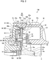
Fig. 2 is an enlarged cross-sectional view showing a configuration in the vicinity of a joint portion between a turbine housing and a bearing housing in a first embodiment of the present invention. -
Fig. 3 is an enlarged cross-sectional view showing a configuration in the vicinity of a joint portion between a turbine housing and a bearing housing in a modification example of the first embodiment of the present invention. -
Fig. 4 is a view showing an example of a shape of a shim in the modification example of the first embodiment of the present invention. -
Fig. 5 is an enlarged cross-sectional view showing a configuration in the vicinity of a joint portion between a turbine housing and a bearing housing in a second embodiment of the present invention. - Next, a turbocharger according to embodiments of the present invention will be described with reference to the drawings.
-
Fig. 1 is a cross-sectional view showing an overall configuration of a turbocharger according to an embodiment of the present invention. - As shown in
Fig. 1 , aturbocharger 10A of the present embodiment includes aturbocharger body 11, acompressor 20, and aturbine 30. For example, theturbocharger 10A is mounted as an auxiliary machine of an engine on an automobile or the like in a state where arotating shaft 14 extends in a horizontal direction. Theturbocharger 10A is supported by a vehicle body or the like via a bracket (not shown), thecompressor 20, theturbine 30, or the like. - The
turbocharger body 11 includes therotating shaft 14, abearing 15A, and a bearinghousing 16. - The rotating
shaft 14 is rotatably supported by thebearing 15A accommodated in the bearinghousing 16. Aturbine wheel 12 is integrally formed on afirst end portion 14a of therotating shaft 14, and acompressor wheel 13 is attached to asecond end portion 14b of therotating shaft 14. - The bearing
housing 16 is formed to accommodate thebearing 15A and to cover therotating shaft 14 from the outside. The bearinghousing 16 includes anopening 16a on a first end portion side of the bearinghousing 16 and anopening 16b on a second end portion side thereof. Thefirst end portion 14a and thesecond end portion 14b of the above-describedrotating shaft 14 protrude toward the outside of the bearinghousing 16 through theopenings turbine wheel 12 and thecompressor wheel 13 is disposed outside the bearinghousing 16. - The
compressor 20 includes thecompressor wheel 13 and acompressor housing 21. Thecompressor 20 is a so-called a centrifugal compressor and boosts air such as outside air. The boosted air is supplied to the engine. - The
compressor wheel 13 is rotated together with the rotatingshaft 14. The compressor wheel is rotated, and air flowing from an inlet of thecompressor housing 21 is moved radially outward while being compressed and is discharged to the outside of thecompressor housing 21 via a scroll or the like. - The
turbine 30 recovers energy of an exhaust gas discharged from an engine (not shown). Theturbine 30 mainly includes theturbine wheel 12 and aturbine housing 31. - The
turbine wheel 12 converts energy of the exhaust gas into rotational energy. Theturbine wheel 12 is accommodated in theturbine housing 31 and includes a plurality of turbine blades 12W in a circumferential direction. Theturbine wheel 12 is rotated by the exhaust gas supplied to the inside of theturbine housing 31. The rotation of theturbine wheel 12 is transmitted to thecompressor wheel 13 via the rotatingshaft 14. - The
turbine housing 31 has anopening 31a at a position facing the bearinghousing 16. An accommodation space for accommodating theturbine wheel 12 is formed inside theturbine housing 31. Theturbine housing 31 includes a gas introduction portion (not shown), ascroll flow path 34, and anexhaust section 36. - The gas introduction portion (not shown) feeds the exhaust gas discharged from the engine (not shown) to the
scroll flow path 34. - The
scroll flow path 34 is formed to be continuous to the gas introduction portion (not shown) and to be continuous in the circumferential direction so as to be located radially outside theturbine wheel 12. Thescroll flow path 34 is formed as a flow path through which the exhaust gas rotating theturbine wheel 12 flows in the circumferential direction. - The
scroll flow path 34 is formed by a scroll formedportion 31s that is formed on an outer peripheral portion of theturbine housing 31 so as to swell radially outward. - A
nozzle flow path 35 is formed to a side of theturbine housing 31, which is close to the bearinghousing 16. Thenozzle flow path 35 is formed over the entire periphery in the circumferential direction such that thescroll flow path 34 communicates with theturbine wheel 12 radially outward. - The exhaust gas discharged from the
turbine wheel 12 flows in theexhaust section 36. Theexhaust section 36 is formed to be continuous from an outer peripheral portion of theturbine wheel 12 in a direction separated away from theturbocharger body 11 along a central axis C of therotating shaft 14. - In the
turbine 30, the exhaust gas which has flowed from gas introduction portion (not shown) flows to an outer peripheral side of theturbine wheel 12 in the circumferential direction along thescroll flow path 34. In this way, the exhaust gas flowing in the circumferential direction flows radially inward through thenozzle flow path 35 and strikes the turbine blades 12W of theturbine wheel 12, and thus, theturbine wheel 12 is rotated. The exhaust gas which has passed through theturbine wheel 12 is discharged from an inner peripheral side of theturbine wheel 12 to theexhaust section 36. - As shown in
Fig. 2 , avariable vane mechanism 50 adjusting the amount of the exhaust gas supplied from thescroll flow path 34 to theturbine wheel 12 through thenozzle flow path 35 is provided innozzle flow path 35. - The
variable vane mechanism 50 includes nozzle mounts 51,nozzle plates 52,vanes 53, and a drive unit (rotating mechanism) 55. - Each of the nozzle mounts 51 is provided on a side of the
nozzle flow path 35, which is close to the bearinghousing 16, and is formed in an annular plate shape positioned on a plane orthogonal to the central axis C. - Each of the
nozzle plates 52 is provided on an opposite side to each of the nozzle mounts 51 with respect to thenozzle flow path 35 with a gap between thenozzle mount 51 and the nozzle plate. Thenozzle flow path 35 is provided between the nozzle mounts 51 and thenozzle plates 52. - Each of the
vanes 53 has a plate shape and is provided between thenozzle mount 51 and thenozzle plate 52. The plurality ofvanes 53 are provided in thenozzle flow path 35, which is continuous in the circumferential direction, at intervals in the circumferential direction. Each of thevanes 53 is rotatably supported in a state of penetrating thenozzle mount 51 in the direction of the central axis C. The plurality of nozzle mounts 51 and the plurality ofnozzle plates 52 are provided in the circumferential direction with a gap, and are fixed by asupport pin 54. - The
drive unit 55 adjusts the angle of each of thevanes 53 by rotating a supporting part of thevanes 53 protruding from the nozzle mounts 51 toward a bearinghousing 16 side. Thedrive unit 55 is provided on the bearinghousing 16 side with respect to the nozzle mounts 51. Thedrive unit 55 includes adrive ring 56 and linkarms 57. - The
drive ring 56 has an annular shape, and is provided radially outside ashaft 54. Thedrive ring 56 is provided to be rotatable in the circumferential direction thereof by an actuator (not shown), or the like. - Each of the
link arms 57 is connected to each of thevanes 53. A first end portion of each of thelink arms 57 is connected to each of thevanes 53, and a second end portion thereof is rotatably connected to thedrive ring 56. When thedrive ring 56 rotates, thelink arms 57 rotate about the supporting part of thevanes 53, and accordingly, the angle of each of thevanes 53 changes. - In the bearing
housing 16, an enlarged diameter portion 16K, which is enlarged radially outward, is formed close to theturbine 30. - The
turbine housing 31 has a connectingportion 31j, which extends to the bearinghousing 16 side from the scroll formedportion 31s through an outer peripheral side of thenozzle mount 51 and surrounds an outer peripheral side of the enlarged diameter portion 16K. Theturbine housing 31 has theopening 31a inside the connectingportion 31j. - The
turbine housing 31 and the bearinghousing 16 are joined by inserting the enlarged diameter portion 16K into theopening 31a, which is inside the connectingportion 31j of theturbine housing 31. - Herein, a connecting portion
heat shielding material 81 is provided between an inner peripheral surface of the connectingportion 31j of theturbine housing 31 and an outer peripheral surface of the enlarged diameter portion 16K of the bearinghousing 16, as aheat shielding portion 80. - In the bearing
housing 16, anaccommodation chamber 100 for accommodating thedrive unit 55 is formed radially outside theopening 16a to be depressed toward the compressor 20 (refer toFig. 1 ). - In the
accommodation chamber 100, an accommodation chamberheat shielding material 84 is provided, as theheat shielding portion 80, on each of a facingsurface 101 facing the nozzle mounts 51 with a gap in the direction of the central axis C, an inner peripheral sideperipheral surface 102 of theaccommodation chamber 100, and an outer peripheral sideperipheral surface 103 of theaccommodation chamber 100. - The above-described nozzle mounts 51 are provided to close the
accommodation chamber 100. Outer peripheral end portions (end portions) 51s of the nozzle mounts 51 each are interposed and supported between theturbine housing 31 and the bearinghousing 16. - A
back plate 41 is provided radially inside the nozzle mounts 51 to close a gap in an outer peripheral portion of thefirst end portion 14a of therotating shaft 14. For example, theback plate 41 is formed of a material having heat resistance such as a stainless steel alloy and Inconel. - An inner peripheral
heat shielding material 82 is provided between theback plate 41 and the bearinghousing 16 as theheat shielding portion 80. - The outer
peripheral end portions 51s, which are located radially outside the nozzle mounts 51, and a mount outer peripheral portionheat shielding material 83 are provided, as theheat shielding portion 80, between theturbine housing 31 and the bearinghousing 16. More specifically, the mount outer peripheral portionheat shielding material 83 includes a firstheat shielding material 83a, a secondheat shielding material 83b, and a thirdheat shielding material 83c. - The first
heat shielding material 83a is provided betweenside surfaces 51a of the nozzle mounts 51 and a facingportion 31f, which is formed in theturbine housing 31 and faces the side surfaces 51a. - The second
heat shielding material 83b is provided between outerperipheral surfaces 51b of the nozzle mounts 51 and theturbine housing 31, which is located radially outside the outer peripheral surfaces. - The third
heat shielding material 83c is provided between side surfaces 51c of the nozzle mounts 51, which face the bearinghousing 16 side, and the bearinghousing 16 facing the side surfaces 51c. - Each of the connecting portion
heat shielding material 81, the inner peripheralheat shielding material 82, and the mount outer peripheral portionheat shielding material 83, each of which is provided as theheat shielding portion 80, is formed of a material having thermal conductivity lower than that of theturbine housing 31. The connecting portionheat shielding material 81, the inner peripheralheat shielding material 82, and the mount outer peripheral portionheat shielding material 83 can be formed of, for example, a heat insulating material or a heat shielding material having thermal conductivity of 0.1 W/m/K or less at the room temperature. For example, as the heat insulating material or the heat shielding material, a porous body, a sheet material, which is made of a ceramic material, a silica material, or the like can be used. The connecting portionheat shielding material 81, the inner peripheralheat shielding material 82, and the mount outer peripheral portionheat shielding material 83 may be formed by covering the heat insulating material or the heat shielding material with a metal net. Coating may be applied to theturbine housing 31, the bearinghousing 16, and the nozzle mounts 51 with the heat shielding material having the thermal conductivity, thereby forming the connecting portionheat shielding material 81, the inner peripheralheat shielding material 82, and the mount outer peripheral portionheat shielding material 83. - The accommodation chamber
heat shielding material 84 formed as theheat shielding portion 80 is formed of a material having thermal conductivity lower than that of theturbine housing 31 as in each of the connecting portionheat shielding material 81, the inner peripheralheat shielding material 82, and the mount outer peripheral portionheat shielding material 83. The accommodation chamberheat shielding material 84 can be formed of, for example, a heat insulating material or a heat shielding material having thermal conductivity of 0.1 W/m/K or less at the room temperature. For example, as the heat insulating material or the heat shielding material, a porous body, a sheet material, which is made of a ceramic material, a silica material, or the like can be used. The accommodation chamberheat shielding material 84 may be formed by covering the heat insulating material or the heat shielding material with a metal net. Coating may be applied to theaccommodation chamber 100 with the heat shielding material having the thermal conductivity, thereby forming the accommodation chamberheat shielding material 84. In particular, the accommodation chamberheat shielding material 84 receives heat radiated from the nozzle mounts 51 closing theaccommodation chamber 100 or thedrive unit 55. For this reason, the accommodation chamberheat shielding material 84 may be formed, for example, in white. - Therefore, according to the
turbocharger 10A of the above-described first embodiment, the nozzle mounts 51 are interposed between theheat shielding portions 80 to suppress an increase in the quantity of heat transmitted from theturbine housing 31 side to the bearinghousing 16 side, and thus, it is possible to inhibit heat on theturbine housing 31 side from being transmitted to the bearinghousing 16 in a configuration where thenozzle flow path 35 including thevanes 53, of which angles are variable, are included. - The mount outer peripheral portion
heat shielding material 83 provided as theheat shielding portion 80 can inhibit heat on theturbine housing 31 side from being transmitted to the bearinghousing 16 via the nozzle mounts 51. - The accommodation chamber
heat shielding material 84 provided as theheat shielding portion 80 can inhibit heat transmitted from theturbine 30 to thedrive unit 55 via the nozzle mounts 51 from propagating to an inner peripheral surface of theaccommodation chamber 100 via air in theaccommodation chamber 100. Therefore, it is possible to inhibit heat on theturbine housing 31 side from being transmitted to the bearinghousing 16. - In this manner, in the
turbocharger 10A including thevanes 53, of which angles are variable, it is possible to suppress energy loss in theturbine 30 and a heat input from theturbine 30 to the bearing. As a result, the operating efficiency of theturbine 30 can be increased, and an increase in the flow rate of oil or the like supplied for cooling or lubrication can be suppressed also in the bearinghousing 16. - A case where the third
heat shielding material 83c of the mount outer peripheral portionheat shielding material 83 is provided between the side surfaces 51c of the nozzle mounts 51 and an outerperipheral end surface 16t of the bearinghousing 16 is described in the first embodiment. For example, the thirdheat shielding material 83c can also be configured as follows. -
Fig. 3 is an enlarged cross-sectional view showing a configuration in the vicinity of a joint portion between a turbine housing and a bearing housing in a modification example of the first embodiment of the present invention.Fig. 4 is a view showing an example of a shape of a shim in the modification example of the first embodiment of the present invention. - As shown in
Fig. 3 , ashim 86 may be provided between the side surfaces 51c of the nozzle mounts 51 and the outerperipheral end surface 16t of the bearinghousing 16. - As shown in
Fig. 4 , theshim 86 integrally includes anannular portion 86r andprotrusion portions 86t. The plurality ofprotrusion portions 86t are formed on one surface of theannular portion 86r at intervals in a circumferential direction. Therefore, each of cut-outportions 86k is formed between theprotrusion portions 86t adjacent to each other in the circumferential direction on the one surface of theannular portion 86r of theshim 86. - The third
heat shielding material 83c of the mount outer peripheral portionheat shielding material 83 is provided to fill the cut-outportions 86k. - In this way, even in the case where the
shim 86 is provided, the mount outer peripheral portionheat shielding material 83 can be provided between the side surfaces 51c of the nozzle mounts 51 and the outerperipheral end surface 16t of the bearinghousing 16. Therefore, it is possible to inhibit heat from being transmitted from the nozzle mounts 51 to the bearinghousing 16, and it is possible to suppress energy loss in theturbine 30 and an heat input from theturbine 30 to the bearinghousing 16. - The
shim 86 is provided, and thus, it is possible to inhibit the mount outer peripheral portionheat shielding material 83 from being destroyed. - Next, a second embodiment of a turbocharger according to the present invention will be described. The second embodiment is different from the first embodiment only in terms of a position where a heat shielding material is provided, and the rest of the configuration of the entire turbocharger is the same as that of the first embodiment. For this reason, in the second embodiment, the same reference numerals are assigned to the same portions as those of the first embodiment, and overlapping descriptions thereof are omitted.
-
Fig. 5 is an enlarged cross-sectional view showing a configuration in the vicinity of a joint portion between a turbine housing and a bearing housing in the second embodiment of the present invention. - As shown in
Fig. 5 , in aturbocharger 10B, a mount surfaceheat shielding material 85, which is theheat shielding portion 80, is provided in a region of thenozzle mount 51, which faces thescroll flow path 34 radially outside thenozzle flow path 35. - In the
turbocharger 10B, theturbine housing 31 is provided with a housing outer peripheralheat shielding material 87 covering only the connectingportion 31j, out of the scroll formedportion 31s and the connectingportion 31j, from the outer periphery of the housing, as theheat shielding portion 80. - Each of the mount surface
heat shielding material 85 and the housing outer peripheralheat shielding material 87, each of which is provided as theheat shielding portion 80, is formed of a material having thermal conductivity lower than that of theturbine housing 31. The mount surfaceheat shielding material 85 and the housing outer peripheralheat shielding material 87 can be formed of, for example, a heat insulating material or a heat shielding material having thermal conductivity of 0.1 W/m/K or less at the room temperature. For example, as the heat insulating material or the heat shielding material, a porous body, a sheet material, which is made of a ceramic material, a silica material, or the like can be used. The mount surfaceheat shielding material 85 and the housing outer peripheralheat shielding material 87 may be formed by covering the heat insulating material or the heat shielding material with a metal net. Coating may be applied to theturbine housing 31 and the nozzle mounts 51 with the heat shielding material having the thermal conductivity, thereby forming the mount surfaceheat shielding material 85 and the housing outer peripheralheat shielding material 87. - Therefore, according to the
turbocharger 10B of the above-described second embodiment, the housing outer peripheralheat shielding material 87, which is provided as theheat shielding portion 80, covers only the connectingportion 31j. Thus, when the connectingportion 31j is heated by heat on theturbine housing 31 side, the heat is unlikely to escape from the connectingportion 31j. Therefore, since the connectingportion 31j is maintained at a high temperature, it is possible to suppress any more heat input from theturbine housing 31 side. Therefore, it is possible to inhibit heat on theturbine housing 31 side from being transmitted to the bearinghousing 16. - Heat of the exhaust gas in the
scroll flow path 34 is unlikely to be transmitted to the nozzle mounts 51 due to the mount surfaceheat shielding material 85 provided as theheat shielding portion 80. Therefore, it is possible to inhibit heat on theturbine housing 31 side from being transmitted to the bearinghousing 16 via the nozzle mounts 51. - In this manner, in the
turbocharger 10B including thevanes 53, of which angles are variable, it is possible to suppress energy loss in theturbine 30 and a heat input from theturbine 30 to the bearing. As a result, the operating efficiency of theturbine 30 can be increased, and an increase in the flow rate of oil or the like supplied for cooling or lubrication can be suppressed also in the bearinghousing 16. - The present invention is not limited to the above-described embodiments, and includes various modifications to the above-described embodiments within the scope which does not depart from the gist of the present invention. That is, the specific shapes, configurations, or the like described in the embodiments are merely examples, and can be appropriately changed.
- In addition, the configuration of each portion such as the
turbocharger body 11, thecompressor 20, theturbine 30, or the like of theturbocharger 10A is not limited to those exemplified above, and may be changed to other configurations. - The present invention can be applied to the turbocharger. According to this invention, in the turbocharger including the variable vanes, it is possible to suppress the energy loss in the turbine and the heat input from the turbine to the bearing.
-
- 10A: turbocharger
- 11: turbocharger body
- 12: turbine wheel
- 12W: turbine blade
- 13: compressor wheel
- 14: rotating shaft
- 14a: first end portion
- 14b: second end portion
- 15A, 15B: bearing
- 16: bearing housing
- 16K: enlarged diameter portion
- 16a: opening
- 16b: opening
- 16s: end surface
- 16t: outer peripheral end surface
- 17: oil supply pipe connection port
- 18: oil drain portion
- 20: compressor
- 30: turbine
- 31: turbine housing
- 31a: opening
- 31j: connecting portion
- 31s: scroll formed portion
- 34: scroll flow path
- 35: nozzle flow path
- 36: exhaust section
- 41: back plate
- 50: variable vane mechanism
- 51: nozzle mount
- 51a: side surface
- 51b: outer peripheral surface
- 51c: side surface
- 51s: outer peripheral end portion (end portion)
- 52: nozzle plate
- 53: vane
- 54: support pin
- 55: drive unit (rotating mechanism)
- 56: drive ring
- 57: link arm
- 80: heat shielding portion
- 81: connecting portion heat shielding material
- 82: inner peripheral heat shielding material
- 83: mount outer peripheral portion heat shielding material
- 83a: first heat shielding material
- 83b: second heat shielding material
- 83c: third heat shielding material
- 84: accommodation chamber heat shielding material
- 85: mount surface heat shielding material
- 86: shim
- 86k: cut-out portion
- 86r: annular portion
- 86t: protrusion portion
- 87: housing outer peripheral heat shielding material
- 100: accommodation chamber
- 101: facing surface
- 102: inner peripheral side peripheral surface
- 103: outer peripheral side peripheral surface
- C: central axis (axis)
Claims (5)
- A turbocharger comprising:a rotating shaft which extends along an axis;a turbine wheel which is provided on a first end portion side of the rotating shaft;a compressor wheel which is provided on a second end portion side of the rotating shaft;a bearing housing which rotatably supports the rotating shaft;a turbine housing which accommodates the turbine wheel;a scroll flow path which is formed in the turbine housing, is continuous in a circumferential direction to be located radially outside the turbine wheel, and allows a gas rotating the turbine wheel to flow therethrough;a nozzle flow path which allows the gas to be introduced radially inward from the scroll flow path and supplies the gas to the turbine wheel;a nozzle mount which is provided on the bearing housing side with respect to the nozzle flow path;a vane which is rotatably supported by the nozzle mount and adjusts an amount of the gas introduced into the nozzle flow path; anda heat shielding portion which suppresses an increase in a quantity of heat transmitted from the turbine housing side to the bearing housing side with the nozzle mount interposed therebetween.
- The turbocharger according to Claim 1,
wherein the heat shielding portion is a mount outer peripheral portion heat shielding material provided between an end portion radially outside the nozzle mount and at least one of the bearing housing or the turbine housing. - The turbocharger according to Claim 1 or 2,
wherein a rotating mechanism rotating the vane is provided on the bearing housing side with respect to the nozzle mount,
an accommodation chamber which accommodates the rotating mechanism is formed in the bearing housing, and
the heat shielding portion is an accommodation chamber heat shielding material provided on an inner peripheral surface of the accommodation chamber. - The turbocharger according to any one of Claims 1 to 3,
wherein the turbine housing includes
a scroll formed portion that forms the scroll flow path, and
a connecting portion that is formed to extend from the scroll formed portion to the bearing housing side, which is an opposite side, with the nozzle mount interposed therebetween, and is connected to the bearing housing, and
the heat shielding portion is a housing outer peripheral heat shielding material covering only the connecting portion, out of the scroll formed portion and the connecting portion, from an outer peripheral side. - The turbocharger according to any one of Claims 1 to 4,
wherein the heat shielding portion is a mount surface heat shielding material provided in a portion of the nozzle mount, the portion facing the scroll flow path side.
Applications Claiming Priority (1)
| Application Number | Priority Date | Filing Date | Title |
|---|---|---|---|
| PCT/JP2016/056762 WO2017149747A1 (en) | 2016-03-04 | 2016-03-04 | Turbocharger |
Publications (3)
| Publication Number | Publication Date |
|---|---|
| EP3404231A1 true EP3404231A1 (en) | 2018-11-21 |
| EP3404231A4 EP3404231A4 (en) | 2018-12-12 |
| EP3404231B1 EP3404231B1 (en) | 2021-05-05 |
Family
ID=59742627
Family Applications (1)
| Application Number | Title | Priority Date | Filing Date |
|---|---|---|---|
| EP16892587.3A Active EP3404231B1 (en) | 2016-03-04 | 2016-03-04 | Turbocharger |
Country Status (5)
| Country | Link |
|---|---|
| US (1) | US10738652B2 (en) |
| EP (1) | EP3404231B1 (en) |
| JP (1) | JP6679710B2 (en) |
| CN (1) | CN108779707B (en) |
| WO (1) | WO2017149747A1 (en) |
Cited By (1)
| Publication number | Priority date | Publication date | Assignee | Title |
|---|---|---|---|---|
| DE112017002684B4 (en) | 2016-05-27 | 2022-10-20 | Ihi Corporation | Variable geometry turbocharger |
Families Citing this family (6)
| Publication number | Priority date | Publication date | Assignee | Title |
|---|---|---|---|---|
| KR20190067850A (en) * | 2016-11-02 | 2019-06-17 | 보르그워너 인코퍼레이티드 | Turbines with multi-part turbine housings |
| CN110573711B (en) * | 2017-09-27 | 2022-04-05 | 三菱重工发动机和增压器株式会社 | Turbine housing and supercharger with same |
| JP7135788B2 (en) * | 2018-11-29 | 2022-09-13 | トヨタ自動車株式会社 | turbocharger |
| JP7251528B2 (en) * | 2020-07-15 | 2023-04-04 | いすゞ自動車株式会社 | Bearing Rust Prevention Device for Variable Displacement Turbocharger |
| US20240068382A1 (en) * | 2021-01-15 | 2024-02-29 | Panasonic Intellectual Property Management Co., Ltd. | Rotary machine and refrigeration device using same |
| US20250347228A1 (en) * | 2022-07-06 | 2025-11-13 | Mitsubishi Heavy Industries Engine & Turbocharger, Ltd. | Turbine and turbocharger |
Family Cites Families (18)
| Publication number | Priority date | Publication date | Assignee | Title |
|---|---|---|---|---|
| NL7313754A (en) | 1973-10-06 | 1975-04-08 | Philips Nv | APERTURE CORRECTION SWITCH FOR TELEVISION. |
| JPS5949323A (en) * | 1982-09-10 | 1984-03-21 | Toyota Central Res & Dev Lab Inc | turbo machine |
| JPS6240232U (en) * | 1985-08-30 | 1987-03-10 | ||
| JPS6267237A (en) * | 1985-09-18 | 1987-03-26 | Hitachi Ltd | Dual passage type exhaust drive turbocharger |
| JPH0219834U (en) * | 1988-07-22 | 1990-02-09 | ||
| DE10220573C1 (en) | 2002-05-08 | 2003-07-03 | Mtu Friedrichshafen Gmbh | IC engine exhaust gas turbocharger has rupture protection enclosing dangerous section of turbocharger housing |
| JP2006194135A (en) * | 2005-01-12 | 2006-07-27 | Nippon Soken Inc | Variable nozzle turbocharger |
| DE602005020701D1 (en) * | 2005-10-18 | 2010-05-27 | Honeywell Int Inc | TURBOLADER AND CARTRIDGE WITH VARIABLE NOZZLE FOR IT |
| US20080271449A1 (en) | 2007-05-01 | 2008-11-06 | Quentin Roberts | Turbocharger with sliding piston, having overlapping fixed and moving vanes |
| JP5076919B2 (en) * | 2008-01-21 | 2012-11-21 | 株式会社Ihi | Insulation cover for turbocharger |
| DE102009005013B4 (en) | 2009-01-17 | 2019-12-12 | Ihi Charging Systems International Gmbh | Connecting arrangement of a turbine housing with a bearing housing and exhaust gas turbocharger |
| DE102009049841B4 (en) * | 2009-10-14 | 2015-01-15 | Mtu Friedrichshafen Gmbh | Gas turbine engine and internal combustion engine |
| WO2011152454A1 (en) | 2010-06-01 | 2011-12-08 | 株式会社Ihi | Stator vane-type turbocharger |
| JP5880463B2 (en) * | 2013-01-29 | 2016-03-09 | 株式会社豊田自動織機 | Turbocharger |
| CN105593475B (en) | 2013-05-14 | 2018-05-04 | 博格华纳公司 | The turbine cylinder of exhaust turbine supercharger |
| JP6331423B2 (en) * | 2014-01-29 | 2018-05-30 | 株式会社Ihi | Variable capacity turbocharger |
| WO2017163657A1 (en) * | 2016-03-25 | 2017-09-28 | 株式会社Ihi | Supercharger |
| CN109072774A (en) * | 2016-05-27 | 2018-12-21 | 株式会社Ihi | Booster |
-
2016
- 2016-03-04 WO PCT/JP2016/056762 patent/WO2017149747A1/en not_active Ceased
- 2016-03-04 EP EP16892587.3A patent/EP3404231B1/en active Active
- 2016-03-04 US US16/077,764 patent/US10738652B2/en not_active Expired - Fee Related
- 2016-03-04 JP JP2018502471A patent/JP6679710B2/en not_active Expired - Fee Related
- 2016-03-04 CN CN201680083052.7A patent/CN108779707B/en not_active Expired - Fee Related
Cited By (1)
| Publication number | Priority date | Publication date | Assignee | Title |
|---|---|---|---|---|
| DE112017002684B4 (en) | 2016-05-27 | 2022-10-20 | Ihi Corporation | Variable geometry turbocharger |
Also Published As
| Publication number | Publication date |
|---|---|
| WO2017149747A1 (en) | 2017-09-08 |
| JP6679710B2 (en) | 2020-04-15 |
| CN108779707A (en) | 2018-11-09 |
| JPWO2017149747A1 (en) | 2018-12-06 |
| US10738652B2 (en) | 2020-08-11 |
| US20190048742A1 (en) | 2019-02-14 |
| CN108779707B (en) | 2020-11-24 |
| EP3404231A4 (en) | 2018-12-12 |
| EP3404231B1 (en) | 2021-05-05 |
Similar Documents
| Publication | Publication Date | Title |
|---|---|---|
| US10738652B2 (en) | Turbocharger | |
| EP2116694B1 (en) | Turbocharger with variable nozzle having vane sealing surfaces | |
| CN101978138B (en) | Gas turbine | |
| US9109510B2 (en) | Gas turbine engine bearing support strut | |
| JP6542246B2 (en) | Variable displacement turbocharger | |
| EP2759687B2 (en) | Seal ring mounting method for turbocharger, and turbocharger | |
| EP2514945B2 (en) | Turbocharger | |
| US11506086B2 (en) | Turbine housing and turbo charger provided with same | |
| EP2573364B1 (en) | Turbocharger with variable nozzle having labyrinth seal for vanes | |
| JP2007278287A (en) | Gas turbine compressor casing flow path ring and stator casing assembly method | |
| US10890109B2 (en) | Turbocharger | |
| EP2283218B1 (en) | Thermal insulation structure | |
| EP2596215B1 (en) | A seal assembly for controlling fluid flow | |
| US8734088B2 (en) | Variable stator vane | |
| US8677765B2 (en) | Gas-turbine combustion chamber with a holding mechanism for a seal for an attachment | |
| US11306613B2 (en) | Turbocharger | |
| EP3542031B1 (en) | Vane arrangement for a turbo-machine | |
| EP3382209B1 (en) | Centrifugal compressor and supercharger | |
| EP3561260A1 (en) | Casing for exhaust turbocharger turbine, exhaust turbocharger turbine, and manufacturing method thereof | |
| JP2020084924A (en) | Turbo charger | |
| CN117321297A (en) | Supercharger |
Legal Events
| Date | Code | Title | Description |
|---|---|---|---|
| STAA | Information on the status of an ep patent application or granted ep patent |
Free format text: STATUS: THE INTERNATIONAL PUBLICATION HAS BEEN MADE |
|
| PUAI | Public reference made under article 153(3) epc to a published international application that has entered the european phase |
Free format text: ORIGINAL CODE: 0009012 |
|
| STAA | Information on the status of an ep patent application or granted ep patent |
Free format text: STATUS: REQUEST FOR EXAMINATION WAS MADE |
|
| REG | Reference to a national code |
Ref country code: DE Ref legal event code: R079 Ref document number: 602016057608 Country of ref document: DE Free format text: PREVIOUS MAIN CLASS: F02B0039000000 Ipc: F01D0017160000 |
|
| 17P | Request for examination filed |
Effective date: 20180813 |
|
| AK | Designated contracting states |
Kind code of ref document: A1 Designated state(s): AL AT BE BG CH CY CZ DE DK EE ES FI FR GB GR HR HU IE IS IT LI LT LU LV MC MK MT NL NO PL PT RO RS SE SI SK SM TR |
|
| AX | Request for extension of the european patent |
Extension state: BA ME |
|
| A4 | Supplementary search report drawn up and despatched |
Effective date: 20181109 |
|
| RIC1 | Information provided on ipc code assigned before grant |
Ipc: F02C 6/12 20060101ALI20181105BHEP Ipc: F02B 39/00 20060101ALI20181105BHEP Ipc: F02B 37/24 20060101ALI20181105BHEP Ipc: F01D 17/16 20060101AFI20181105BHEP |
|
| DAV | Request for validation of the european patent (deleted) | ||
| DAX | Request for extension of the european patent (deleted) | ||
| STAA | Information on the status of an ep patent application or granted ep patent |
Free format text: STATUS: EXAMINATION IS IN PROGRESS |
|
| 17Q | First examination report despatched |
Effective date: 20190729 |
|
| GRAP | Despatch of communication of intention to grant a patent |
Free format text: ORIGINAL CODE: EPIDOSNIGR1 |
|
| STAA | Information on the status of an ep patent application or granted ep patent |
Free format text: STATUS: GRANT OF PATENT IS INTENDED |
|
| INTG | Intention to grant announced |
Effective date: 20201127 |
|
| GRAS | Grant fee paid |
Free format text: ORIGINAL CODE: EPIDOSNIGR3 |
|
| GRAA | (expected) grant |
Free format text: ORIGINAL CODE: 0009210 |
|
| STAA | Information on the status of an ep patent application or granted ep patent |
Free format text: STATUS: THE PATENT HAS BEEN GRANTED |
|
| AK | Designated contracting states |
Kind code of ref document: B1 Designated state(s): AL AT BE BG CH CY CZ DE DK EE ES FI FR GB GR HR HU IE IS IT LI LT LU LV MC MK MT NL NO PL PT RO RS SE SI SK SM TR |
|
| REG | Reference to a national code |
Ref country code: GB Ref legal event code: FG4D |
|
| REG | Reference to a national code |
Ref country code: CH Ref legal event code: EP |
|
| REG | Reference to a national code |
Ref country code: AT Ref legal event code: REF Ref document number: 1390055 Country of ref document: AT Kind code of ref document: T Effective date: 20210515 |
|
| REG | Reference to a national code |
Ref country code: IE Ref legal event code: FG4D |
|
| REG | Reference to a national code |
Ref country code: DE Ref legal event code: R096 Ref document number: 602016057608 Country of ref document: DE |
|
| REG | Reference to a national code |
Ref country code: LT Ref legal event code: MG9D |
|
| REG | Reference to a national code |
Ref country code: AT Ref legal event code: MK05 Ref document number: 1390055 Country of ref document: AT Kind code of ref document: T Effective date: 20210505 |
|
| PG25 | Lapsed in a contracting state [announced via postgrant information from national office to epo] |
Ref country code: HR Free format text: LAPSE BECAUSE OF FAILURE TO SUBMIT A TRANSLATION OF THE DESCRIPTION OR TO PAY THE FEE WITHIN THE PRESCRIBED TIME-LIMIT Effective date: 20210505 Ref country code: AT Free format text: LAPSE BECAUSE OF FAILURE TO SUBMIT A TRANSLATION OF THE DESCRIPTION OR TO PAY THE FEE WITHIN THE PRESCRIBED TIME-LIMIT Effective date: 20210505 Ref country code: BG Free format text: LAPSE BECAUSE OF FAILURE TO SUBMIT A TRANSLATION OF THE DESCRIPTION OR TO PAY THE FEE WITHIN THE PRESCRIBED TIME-LIMIT Effective date: 20210805 Ref country code: FI Free format text: LAPSE BECAUSE OF FAILURE TO SUBMIT A TRANSLATION OF THE DESCRIPTION OR TO PAY THE FEE WITHIN THE PRESCRIBED TIME-LIMIT Effective date: 20210505 Ref country code: LT Free format text: LAPSE BECAUSE OF FAILURE TO SUBMIT A TRANSLATION OF THE DESCRIPTION OR TO PAY THE FEE WITHIN THE PRESCRIBED TIME-LIMIT Effective date: 20210505 |
|
| PG25 | Lapsed in a contracting state [announced via postgrant information from national office to epo] |
Ref country code: LV Free format text: LAPSE BECAUSE OF FAILURE TO SUBMIT A TRANSLATION OF THE DESCRIPTION OR TO PAY THE FEE WITHIN THE PRESCRIBED TIME-LIMIT Effective date: 20210505 Ref country code: IS Free format text: LAPSE BECAUSE OF FAILURE TO SUBMIT A TRANSLATION OF THE DESCRIPTION OR TO PAY THE FEE WITHIN THE PRESCRIBED TIME-LIMIT Effective date: 20210905 Ref country code: GR Free format text: LAPSE BECAUSE OF FAILURE TO SUBMIT A TRANSLATION OF THE DESCRIPTION OR TO PAY THE FEE WITHIN THE PRESCRIBED TIME-LIMIT Effective date: 20210806 Ref country code: NO Free format text: LAPSE BECAUSE OF FAILURE TO SUBMIT A TRANSLATION OF THE DESCRIPTION OR TO PAY THE FEE WITHIN THE PRESCRIBED TIME-LIMIT Effective date: 20210805 Ref country code: PT Free format text: LAPSE BECAUSE OF FAILURE TO SUBMIT A TRANSLATION OF THE DESCRIPTION OR TO PAY THE FEE WITHIN THE PRESCRIBED TIME-LIMIT Effective date: 20210906 Ref country code: PL Free format text: LAPSE BECAUSE OF FAILURE TO SUBMIT A TRANSLATION OF THE DESCRIPTION OR TO PAY THE FEE WITHIN THE PRESCRIBED TIME-LIMIT Effective date: 20210505 Ref country code: RS Free format text: LAPSE BECAUSE OF FAILURE TO SUBMIT A TRANSLATION OF THE DESCRIPTION OR TO PAY THE FEE WITHIN THE PRESCRIBED TIME-LIMIT Effective date: 20210505 Ref country code: SE Free format text: LAPSE BECAUSE OF FAILURE TO SUBMIT A TRANSLATION OF THE DESCRIPTION OR TO PAY THE FEE WITHIN THE PRESCRIBED TIME-LIMIT Effective date: 20210505 |
|
| REG | Reference to a national code |
Ref country code: NL Ref legal event code: MP Effective date: 20210505 |
|
| PG25 | Lapsed in a contracting state [announced via postgrant information from national office to epo] |
Ref country code: NL Free format text: LAPSE BECAUSE OF FAILURE TO SUBMIT A TRANSLATION OF THE DESCRIPTION OR TO PAY THE FEE WITHIN THE PRESCRIBED TIME-LIMIT Effective date: 20210505 |
|
| PG25 | Lapsed in a contracting state [announced via postgrant information from national office to epo] |
Ref country code: SK Free format text: LAPSE BECAUSE OF FAILURE TO SUBMIT A TRANSLATION OF THE DESCRIPTION OR TO PAY THE FEE WITHIN THE PRESCRIBED TIME-LIMIT Effective date: 20210505 Ref country code: SM Free format text: LAPSE BECAUSE OF FAILURE TO SUBMIT A TRANSLATION OF THE DESCRIPTION OR TO PAY THE FEE WITHIN THE PRESCRIBED TIME-LIMIT Effective date: 20210505 Ref country code: RO Free format text: LAPSE BECAUSE OF FAILURE TO SUBMIT A TRANSLATION OF THE DESCRIPTION OR TO PAY THE FEE WITHIN THE PRESCRIBED TIME-LIMIT Effective date: 20210505 Ref country code: ES Free format text: LAPSE BECAUSE OF FAILURE TO SUBMIT A TRANSLATION OF THE DESCRIPTION OR TO PAY THE FEE WITHIN THE PRESCRIBED TIME-LIMIT Effective date: 20210505 Ref country code: EE Free format text: LAPSE BECAUSE OF FAILURE TO SUBMIT A TRANSLATION OF THE DESCRIPTION OR TO PAY THE FEE WITHIN THE PRESCRIBED TIME-LIMIT Effective date: 20210505 Ref country code: CZ Free format text: LAPSE BECAUSE OF FAILURE TO SUBMIT A TRANSLATION OF THE DESCRIPTION OR TO PAY THE FEE WITHIN THE PRESCRIBED TIME-LIMIT Effective date: 20210505 Ref country code: DK Free format text: LAPSE BECAUSE OF FAILURE TO SUBMIT A TRANSLATION OF THE DESCRIPTION OR TO PAY THE FEE WITHIN THE PRESCRIBED TIME-LIMIT Effective date: 20210505 |
|
| REG | Reference to a national code |
Ref country code: DE Ref legal event code: R097 Ref document number: 602016057608 Country of ref document: DE |
|
| PLBE | No opposition filed within time limit |
Free format text: ORIGINAL CODE: 0009261 |
|
| STAA | Information on the status of an ep patent application or granted ep patent |
Free format text: STATUS: NO OPPOSITION FILED WITHIN TIME LIMIT |
|
| 26N | No opposition filed |
Effective date: 20220208 |
|
| PGFP | Annual fee paid to national office [announced via postgrant information from national office to epo] |
Ref country code: DE Payment date: 20220203 Year of fee payment: 7 |
|
| PG25 | Lapsed in a contracting state [announced via postgrant information from national office to epo] |
Ref country code: IS Free format text: LAPSE BECAUSE OF FAILURE TO SUBMIT A TRANSLATION OF THE DESCRIPTION OR TO PAY THE FEE WITHIN THE PRESCRIBED TIME-LIMIT Effective date: 20210905 Ref country code: AL Free format text: LAPSE BECAUSE OF FAILURE TO SUBMIT A TRANSLATION OF THE DESCRIPTION OR TO PAY THE FEE WITHIN THE PRESCRIBED TIME-LIMIT Effective date: 20210505 |
|
| PG25 | Lapsed in a contracting state [announced via postgrant information from national office to epo] |
Ref country code: IT Free format text: LAPSE BECAUSE OF FAILURE TO SUBMIT A TRANSLATION OF THE DESCRIPTION OR TO PAY THE FEE WITHIN THE PRESCRIBED TIME-LIMIT Effective date: 20210505 |
|
| PG25 | Lapsed in a contracting state [announced via postgrant information from national office to epo] |
Ref country code: MC Free format text: LAPSE BECAUSE OF FAILURE TO SUBMIT A TRANSLATION OF THE DESCRIPTION OR TO PAY THE FEE WITHIN THE PRESCRIBED TIME-LIMIT Effective date: 20210505 |
|
| REG | Reference to a national code |
Ref country code: CH Ref legal event code: PL |
|
| GBPC | Gb: european patent ceased through non-payment of renewal fee |
Effective date: 20220304 |
|
| REG | Reference to a national code |
Ref country code: BE Ref legal event code: MM Effective date: 20220331 |
|
| PG25 | Lapsed in a contracting state [announced via postgrant information from national office to epo] |
Ref country code: LU Free format text: LAPSE BECAUSE OF NON-PAYMENT OF DUE FEES Effective date: 20220304 Ref country code: LI Free format text: LAPSE BECAUSE OF NON-PAYMENT OF DUE FEES Effective date: 20220331 Ref country code: IE Free format text: LAPSE BECAUSE OF NON-PAYMENT OF DUE FEES Effective date: 20220304 Ref country code: GB Free format text: LAPSE BECAUSE OF NON-PAYMENT OF DUE FEES Effective date: 20220304 Ref country code: FR Free format text: LAPSE BECAUSE OF NON-PAYMENT OF DUE FEES Effective date: 20220331 Ref country code: CH Free format text: LAPSE BECAUSE OF NON-PAYMENT OF DUE FEES Effective date: 20220331 |
|
| PG25 | Lapsed in a contracting state [announced via postgrant information from national office to epo] |
Ref country code: BE Free format text: LAPSE BECAUSE OF NON-PAYMENT OF DUE FEES Effective date: 20220331 |
|
| REG | Reference to a national code |
Ref country code: DE Ref legal event code: R119 Ref document number: 602016057608 Country of ref document: DE |
|
| PG25 | Lapsed in a contracting state [announced via postgrant information from national office to epo] |
Ref country code: DE Free format text: LAPSE BECAUSE OF NON-PAYMENT OF DUE FEES Effective date: 20231003 |
|
| PG25 | Lapsed in a contracting state [announced via postgrant information from national office to epo] |
Ref country code: HU Free format text: LAPSE BECAUSE OF FAILURE TO SUBMIT A TRANSLATION OF THE DESCRIPTION OR TO PAY THE FEE WITHIN THE PRESCRIBED TIME-LIMIT; INVALID AB INITIO Effective date: 20160304 |
|
| PG25 | Lapsed in a contracting state [announced via postgrant information from national office to epo] |
Ref country code: MK Free format text: LAPSE BECAUSE OF FAILURE TO SUBMIT A TRANSLATION OF THE DESCRIPTION OR TO PAY THE FEE WITHIN THE PRESCRIBED TIME-LIMIT Effective date: 20210505 Ref country code: CY Free format text: LAPSE BECAUSE OF FAILURE TO SUBMIT A TRANSLATION OF THE DESCRIPTION OR TO PAY THE FEE WITHIN THE PRESCRIBED TIME-LIMIT Effective date: 20210505 |
|
| PG25 | Lapsed in a contracting state [announced via postgrant information from national office to epo] |
Ref country code: TR Free format text: LAPSE BECAUSE OF FAILURE TO SUBMIT A TRANSLATION OF THE DESCRIPTION OR TO PAY THE FEE WITHIN THE PRESCRIBED TIME-LIMIT Effective date: 20210505 |
|
| PG25 | Lapsed in a contracting state [announced via postgrant information from national office to epo] |
Ref country code: MT Free format text: LAPSE BECAUSE OF FAILURE TO SUBMIT A TRANSLATION OF THE DESCRIPTION OR TO PAY THE FEE WITHIN THE PRESCRIBED TIME-LIMIT Effective date: 20210505 |