EP3404228A1 - Regeneration eines partikelfilters oder vier-wege-katalysators in einer abgasanlage eines verbrennungsmotors - Google Patents
Regeneration eines partikelfilters oder vier-wege-katalysators in einer abgasanlage eines verbrennungsmotors Download PDFInfo
- Publication number
- EP3404228A1 EP3404228A1 EP18164849.4A EP18164849A EP3404228A1 EP 3404228 A1 EP3404228 A1 EP 3404228A1 EP 18164849 A EP18164849 A EP 18164849A EP 3404228 A1 EP3404228 A1 EP 3404228A1
- Authority
- EP
- European Patent Office
- Prior art keywords
- combustion engine
- internal combustion
- particulate filter
- exhaust
- way catalyst
- Prior art date
- Legal status (The legal status is an assumption and is not a legal conclusion. Google has not performed a legal analysis and makes no representation as to the accuracy of the status listed.)
- Granted
Links
Images

Classifications
-
- F—MECHANICAL ENGINEERING; LIGHTING; HEATING; WEAPONS; BLASTING
- F01—MACHINES OR ENGINES IN GENERAL; ENGINE PLANTS IN GENERAL; STEAM ENGINES
- F01N—GAS-FLOW SILENCERS OR EXHAUST APPARATUS FOR MACHINES OR ENGINES IN GENERAL; GAS-FLOW SILENCERS OR EXHAUST APPARATUS FOR INTERNAL COMBUSTION ENGINES
- F01N3/00—Exhaust or silencing apparatus having means for purifying, rendering innocuous, or otherwise treating exhaust
- F01N3/02—Exhaust or silencing apparatus having means for purifying, rendering innocuous, or otherwise treating exhaust for cooling, or for removing solid constituents of, exhaust
- F01N3/021—Exhaust or silencing apparatus having means for purifying, rendering innocuous, or otherwise treating exhaust for cooling, or for removing solid constituents of, exhaust by means of filters
- F01N3/023—Exhaust or silencing apparatus having means for purifying, rendering innocuous, or otherwise treating exhaust for cooling, or for removing solid constituents of, exhaust by means of filters using means for regenerating the filters, e.g. by burning trapped particles
- F01N3/029—Exhaust or silencing apparatus having means for purifying, rendering innocuous, or otherwise treating exhaust for cooling, or for removing solid constituents of, exhaust by means of filters using means for regenerating the filters, e.g. by burning trapped particles by adding non-fuel substances to exhaust
- F01N3/0293—Exhaust or silencing apparatus having means for purifying, rendering innocuous, or otherwise treating exhaust for cooling, or for removing solid constituents of, exhaust by means of filters using means for regenerating the filters, e.g. by burning trapped particles by adding non-fuel substances to exhaust injecting substances in exhaust stream
-
- F—MECHANICAL ENGINEERING; LIGHTING; HEATING; WEAPONS; BLASTING
- F02—COMBUSTION ENGINES; HOT-GAS OR COMBUSTION-PRODUCT ENGINE PLANTS
- F02D—CONTROLLING COMBUSTION ENGINES
- F02D41/00—Electrical control of supply of combustible mixture or its constituents
- F02D41/02—Circuit arrangements for generating control signals
- F02D41/021—Introducing corrections for particular conditions exterior to the engine
- F02D41/0235—Introducing corrections for particular conditions exterior to the engine in relation with the state of the exhaust gas treating apparatus
- F02D41/027—Introducing corrections for particular conditions exterior to the engine in relation with the state of the exhaust gas treating apparatus to purge or regenerate the exhaust gas treating apparatus
-
- F—MECHANICAL ENGINEERING; LIGHTING; HEATING; WEAPONS; BLASTING
- F01—MACHINES OR ENGINES IN GENERAL; ENGINE PLANTS IN GENERAL; STEAM ENGINES
- F01N—GAS-FLOW SILENCERS OR EXHAUST APPARATUS FOR MACHINES OR ENGINES IN GENERAL; GAS-FLOW SILENCERS OR EXHAUST APPARATUS FOR INTERNAL COMBUSTION ENGINES
- F01N3/00—Exhaust or silencing apparatus having means for purifying, rendering innocuous, or otherwise treating exhaust
- F01N3/02—Exhaust or silencing apparatus having means for purifying, rendering innocuous, or otherwise treating exhaust for cooling, or for removing solid constituents of, exhaust
- F01N3/021—Exhaust or silencing apparatus having means for purifying, rendering innocuous, or otherwise treating exhaust for cooling, or for removing solid constituents of, exhaust by means of filters
- F01N3/023—Exhaust or silencing apparatus having means for purifying, rendering innocuous, or otherwise treating exhaust for cooling, or for removing solid constituents of, exhaust by means of filters using means for regenerating the filters, e.g. by burning trapped particles
-
- F—MECHANICAL ENGINEERING; LIGHTING; HEATING; WEAPONS; BLASTING
- F01—MACHINES OR ENGINES IN GENERAL; ENGINE PLANTS IN GENERAL; STEAM ENGINES
- F01N—GAS-FLOW SILENCERS OR EXHAUST APPARATUS FOR MACHINES OR ENGINES IN GENERAL; GAS-FLOW SILENCERS OR EXHAUST APPARATUS FOR INTERNAL COMBUSTION ENGINES
- F01N3/00—Exhaust or silencing apparatus having means for purifying, rendering innocuous, or otherwise treating exhaust
- F01N3/08—Exhaust or silencing apparatus having means for purifying, rendering innocuous, or otherwise treating exhaust for rendering innocuous
- F01N3/10—Exhaust or silencing apparatus having means for purifying, rendering innocuous, or otherwise treating exhaust for rendering innocuous by thermal or catalytic conversion of noxious components of exhaust
- F01N3/18—Exhaust or silencing apparatus having means for purifying, rendering innocuous, or otherwise treating exhaust for rendering innocuous by thermal or catalytic conversion of noxious components of exhaust characterised by methods of operation; Control
- F01N3/20—Exhaust or silencing apparatus having means for purifying, rendering innocuous, or otherwise treating exhaust for rendering innocuous by thermal or catalytic conversion of noxious components of exhaust characterised by methods of operation; Control specially adapted for catalytic conversion ; Methods of operation or control of catalytic converters
-
- F—MECHANICAL ENGINEERING; LIGHTING; HEATING; WEAPONS; BLASTING
- F01—MACHINES OR ENGINES IN GENERAL; ENGINE PLANTS IN GENERAL; STEAM ENGINES
- F01N—GAS-FLOW SILENCERS OR EXHAUST APPARATUS FOR MACHINES OR ENGINES IN GENERAL; GAS-FLOW SILENCERS OR EXHAUST APPARATUS FOR INTERNAL COMBUSTION ENGINES
- F01N9/00—Electrical control of exhaust gas treating apparatus
- F01N9/002—Electrical control of exhaust gas treating apparatus of filter regeneration, e.g. detection of clogging
-
- F—MECHANICAL ENGINEERING; LIGHTING; HEATING; WEAPONS; BLASTING
- F02—COMBUSTION ENGINES; HOT-GAS OR COMBUSTION-PRODUCT ENGINE PLANTS
- F02D—CONTROLLING COMBUSTION ENGINES
- F02D41/00—Electrical control of supply of combustible mixture or its constituents
- F02D41/02—Circuit arrangements for generating control signals
- F02D41/021—Introducing corrections for particular conditions exterior to the engine
- F02D41/0235—Introducing corrections for particular conditions exterior to the engine in relation with the state of the exhaust gas treating apparatus
- F02D41/027—Introducing corrections for particular conditions exterior to the engine in relation with the state of the exhaust gas treating apparatus to purge or regenerate the exhaust gas treating apparatus
- F02D41/029—Introducing corrections for particular conditions exterior to the engine in relation with the state of the exhaust gas treating apparatus to purge or regenerate the exhaust gas treating apparatus the exhaust gas treating apparatus being a particulate filter
-
- F—MECHANICAL ENGINEERING; LIGHTING; HEATING; WEAPONS; BLASTING
- F02—COMBUSTION ENGINES; HOT-GAS OR COMBUSTION-PRODUCT ENGINE PLANTS
- F02D—CONTROLLING COMBUSTION ENGINES
- F02D41/00—Electrical control of supply of combustible mixture or its constituents
- F02D41/02—Circuit arrangements for generating control signals
- F02D41/04—Introducing corrections for particular operating conditions
- F02D41/042—Introducing corrections for particular operating conditions for stopping the engine
-
- F—MECHANICAL ENGINEERING; LIGHTING; HEATING; WEAPONS; BLASTING
- F02—COMBUSTION ENGINES; HOT-GAS OR COMBUSTION-PRODUCT ENGINE PLANTS
- F02N—STARTING OF COMBUSTION ENGINES; STARTING AIDS FOR SUCH ENGINES, NOT OTHERWISE PROVIDED FOR
- F02N11/00—Starting of engines by means of electric motors
- F02N11/08—Circuits or control means specially adapted for starting of engines
- F02N11/0814—Circuits or control means specially adapted for starting of engines comprising means for controlling automatic idle-start-stop
- F02N11/0818—Conditions for starting or stopping the engine or for deactivating the idle-start-stop mode
- F02N11/0833—Vehicle conditions
-
- F—MECHANICAL ENGINEERING; LIGHTING; HEATING; WEAPONS; BLASTING
- F01—MACHINES OR ENGINES IN GENERAL; ENGINE PLANTS IN GENERAL; STEAM ENGINES
- F01N—GAS-FLOW SILENCERS OR EXHAUST APPARATUS FOR MACHINES OR ENGINES IN GENERAL; GAS-FLOW SILENCERS OR EXHAUST APPARATUS FOR INTERNAL COMBUSTION ENGINES
- F01N2260/00—Exhaust treating devices having provisions not otherwise provided for
- F01N2260/04—Exhaust treating devices having provisions not otherwise provided for for regeneration or reactivation, e.g. of catalyst
-
- F—MECHANICAL ENGINEERING; LIGHTING; HEATING; WEAPONS; BLASTING
- F01—MACHINES OR ENGINES IN GENERAL; ENGINE PLANTS IN GENERAL; STEAM ENGINES
- F01N—GAS-FLOW SILENCERS OR EXHAUST APPARATUS FOR MACHINES OR ENGINES IN GENERAL; GAS-FLOW SILENCERS OR EXHAUST APPARATUS FOR INTERNAL COMBUSTION ENGINES
- F01N2900/00—Details of electrical control or of the monitoring of the exhaust gas treating apparatus
- F01N2900/04—Methods of control or diagnosing
- F01N2900/0412—Methods of control or diagnosing using pre-calibrated maps, tables or charts
-
- F—MECHANICAL ENGINEERING; LIGHTING; HEATING; WEAPONS; BLASTING
- F01—MACHINES OR ENGINES IN GENERAL; ENGINE PLANTS IN GENERAL; STEAM ENGINES
- F01N—GAS-FLOW SILENCERS OR EXHAUST APPARATUS FOR MACHINES OR ENGINES IN GENERAL; GAS-FLOW SILENCERS OR EXHAUST APPARATUS FOR INTERNAL COMBUSTION ENGINES
- F01N2900/00—Details of electrical control or of the monitoring of the exhaust gas treating apparatus
- F01N2900/06—Parameters used for exhaust control or diagnosing
- F01N2900/08—Parameters used for exhaust control or diagnosing said parameters being related to the engine
-
- F—MECHANICAL ENGINEERING; LIGHTING; HEATING; WEAPONS; BLASTING
- F01—MACHINES OR ENGINES IN GENERAL; ENGINE PLANTS IN GENERAL; STEAM ENGINES
- F01N—GAS-FLOW SILENCERS OR EXHAUST APPARATUS FOR MACHINES OR ENGINES IN GENERAL; GAS-FLOW SILENCERS OR EXHAUST APPARATUS FOR INTERNAL COMBUSTION ENGINES
- F01N2900/00—Details of electrical control or of the monitoring of the exhaust gas treating apparatus
- F01N2900/06—Parameters used for exhaust control or diagnosing
- F01N2900/14—Parameters used for exhaust control or diagnosing said parameters being related to the exhaust gas
- F01N2900/1404—Exhaust gas temperature
-
- F—MECHANICAL ENGINEERING; LIGHTING; HEATING; WEAPONS; BLASTING
- F02—COMBUSTION ENGINES; HOT-GAS OR COMBUSTION-PRODUCT ENGINE PLANTS
- F02D—CONTROLLING COMBUSTION ENGINES
- F02D2200/00—Input parameters for engine control
- F02D2200/02—Input parameters for engine control the parameters being related to the engine
- F02D2200/10—Parameters related to the engine output, e.g. engine torque or engine speed
- F02D2200/101—Engine speed
-
- Y—GENERAL TAGGING OF NEW TECHNOLOGICAL DEVELOPMENTS; GENERAL TAGGING OF CROSS-SECTIONAL TECHNOLOGIES SPANNING OVER SEVERAL SECTIONS OF THE IPC; TECHNICAL SUBJECTS COVERED BY FORMER USPC CROSS-REFERENCE ART COLLECTIONS [XRACs] AND DIGESTS
- Y02—TECHNOLOGIES OR APPLICATIONS FOR MITIGATION OR ADAPTATION AGAINST CLIMATE CHANGE
- Y02T—CLIMATE CHANGE MITIGATION TECHNOLOGIES RELATED TO TRANSPORTATION
- Y02T10/00—Road transport of goods or passengers
- Y02T10/10—Internal combustion engine [ICE] based vehicles
- Y02T10/40—Engine management systems
Definitions
- the invention relates to a device and a method for the regeneration of a particulate filter or a four-way catalytic converter in an exhaust system of an internal combustion engine.
- ⁇ 1
- additional measures are required. These come as measures, for example, a temperature increase by a Zündwinkelver ein, a temporary lean adjustment of the gasoline engine, the injection of secondary air into the exhaust system or a combination of these measures in question.
- An ignition angle adjustment in the direction of late in combination with a lean adjustment of the gasoline engine is preferably used so far, since this method requires no additional components and can deliver a sufficient amount of oxygen in most operating points of the gasoline engine.
- the aim is to bring the catalysts in the exhaust passage of the internal combustion engine after a cold start as quickly as possible to an operating temperature in order to achieve as fast as possible a high conversion rate for harmful exhaust gas components.
- a method for the regeneration of a particulate filter in an exhaust system of an internal combustion engine wherein the temperature of the exhaust gas of the internal combustion engine is adjusted by a corresponding lambda control to ensure the necessary for the regeneration of the particulate filter temperature and a simultaneous presence of residual oxygen in the exhaust passage of the internal combustion engine.
- a disadvantage of such a method is that it comes through the lean adjustment of the internal combustion engine to increase the nitrogen oxide emissions in the exhaust gas during the regeneration of the particulate filter.
- a spark ignition internal combustion engine in whose exhaust system, a particulate filter is arranged, wherein for the regeneration of the particulate filter, a multi-stage process is performed in order to reduce the ride comfort during the regeneration of the particulate filter as little as possible.
- a passive regeneration of the particulate filter in a coasting phase of the internal combustion engine is combined as a "mildest" measure with corresponding active measures for regeneration, wherein in a multi-stage process the measures are selected which are carried out with the least intervention in the ride comfort or the performance of the internal combustion engine can be.
- a disadvantage of such a method is that even here comes in the active measures to a lean adjustment of the combustion air ratio of the internal combustion engine and an associated increase in nitrogen oxide emissions.
- the DE 10 2012 022 153 A1 discloses a method for regenerating a particulate filter in the exhaust passage of a gasoline engine, wherein in a first step, the temperature of the particulate filter or an exhaust gas mass flow is determined by the particulate filter, and upon reaching a regeneration temperature of the particulate filter, the soot retained in the particulate filter is oxidized by the oxygen content in the exhaust gas is increased beyond a stoichiometric exhaust gas.
- From the DE 10 2010 046 899 A1 is a regeneration of a particulate filter in the exhaust passage of an internal combustion engine known, wherein the regeneration takes place during the shutdown of the internal combustion engine.
- an adjustment of the combustion air ratio in the direction of "lean" immediately before switching off the ignition when the particulate filter has a corresponding load and the temperature of the particulate filter is high enough to allow a partial regeneration of the particulate filter when switching off the internal combustion engine.
- the proposed method allows only the regeneration of a small subset of retained in the particulate filter soot, since the period in which oxygen-rich air is promoted after stopping the injection and the ignition in the exhaust duct is relatively short.
- exhaust aftertreatment systems are known in which the temperature of the particulate filter is increased by engine measures, in particular by an adjustment of the ignition angle in the direction "late” until the regeneration temperature of the particulate filter is reached, and the oxygen required for the oxidation of the retained particulate matter in the carbon black Exhaust duct is supplied via a secondary air system. But this always requires a secondary air system, which significantly increases the cost of the internal combustion engine.
- the invention is based on the object, in an exhaust system without secondary air system to allow at least substantially neutral emissions regeneration of the particulate filter and overcome the known from the prior art disadvantages.
- regeneration of the particulate filter in particular regeneration in several substeps, can take place without a significant increase in emissions, in particular nitrogen oxide emissions, occurring during regeneration.
- no lean adjustment of the internal combustion engine is necessary.
- exhaust gas purification and conversion of the pollutants by a three-way catalyst can be ensured throughout the engine operation, and it is not necessary to take additional measures for exhaust aftertreatment during the regeneration of the particulate filter.
- the speed of the internal combustion engine is raised before switching off to a speed above the threshold value when the engine is idling at the time of Abschaltginses.
- the threshold value for the engine speed is above the normal idling speed of the internal combustion engine.
- the threshold for the engine speed is above 900 U / min. Since passenger car engines usually have an idling speed of 650 rpm to 900 rpm, it can be ensured by such a threshold that a sufficient amount of oxygen enters the exhaust passage of the internal combustion engine.
- the fuel injection into the combustion chambers of the internal combustion engine is only switched off when the temperature of the particle filter or the four-way catalytic converter or the exhaust gas temperature is above a threshold temperature.
- the use of the start / stop system for active regeneration is used continuously.
- the engine also goes into the stop phase, ie injection even if the filter is not regenerated. This is done from the driving point of view.
- the vehicle must always behave the same way.
- For regeneration of the particulate filter i.
- the threshold temperature is preferably in the range between 550 ° C and 750 ° C. In this temperature range, oxidation of the soot retained in the particle filter is possible without the risk of thermal damage to the particle filter.
- a throttle valve in the intake passage of the internal combustion engine is completely opened when the internal combustion engine is switched off.
- the exhaust gas channel supplied amount of air and thus the amount of oxygen, which for oxidation of the soot retained in the particulate filter or in the four-way catalyst is increased.
- a larger subset of the soot particles can be oxidized.
- fewer regeneration steps are necessary until complete regeneration of the particulate filter.
- the oxidation can be restrained by a position of the throttle valve, so as not to thermally overheat the filter. This too is optional depending on the project.
- the shutdown signal of the internal combustion engine is triggered by a start-stop system of the internal combustion engine.
- a start-stop system the shutdown of the engine takes place much more frequently than in an internal combustion engine without start-stop system, for example, when stopped at a traffic light.
- the number of regeneration phases is increased, as a result of which the particle mass discharged from the particle filter can be increased.
- a substantially complete regeneration of the particulate filter can thus be achieved within a comparatively short time.
- the method is started when the loading of the particulate filter or the four-way catalyst is above a threshold value for the loading of the particulate filter or the four-way catalyst.
- a threshold value for the loading of the particulate filter or the four-way catalyst it is in principle also possible to carry out the process independently of the loading state of the particle filter or the four-way catalyst.
- the initiation of the method by increasing the speed of the internal combustion engine before the shutdown process is particularly advantageous when the particulate filter has reached a first threshold for the loading of the particulate filter or the four-way catalyst.
- the exhaust gas temperature is raised upon detection of a timely shutdown request of the internal combustion engine.
- the particulate filter or the four-way catalyst can be heated to a regeneration temperature, so that the introduced by the proposed method in the exhaust gas channel oxygen also finds a sufficient temperature for the oxidation of the soot.
- the temperature may also be raised to accelerate soot burn-up on the particulate filter and discharge more soot from the particulate filter or four-way catalyst in the time-limited window between fuel injection shutdown and engine stall.
- a device for exhaust-gas aftertreatment of an internal combustion engine with an exhaust system in which a particle filter or a four-way catalytic converter is arranged, as well as with a control device with a machine-readable program code is achieved, wherein the control device is configured to execute an embodiment of the program code Perform procedure.
- the particle filter or the four-way catalyst is arranged close to the engine as the first component of the exhaust aftertreatment.
- the regeneration temperature of at least 550 ° C can be achieved comparatively easily. This makes it possible to efficiently use the introduced during the shutdown of the engine in the exhaust duct fresh air for the oxidation of retained in the particulate filter or four-way catalyst soot.
- a NOx storage catalytic converter is additionally provided in the exhaust duct of the internal combustion engine, then it is particularly advantageous if the particle filter or four-way catalytic converter is arranged as the first component of the exhaust gas aftertreatment and the NOx storage catalytic converter downstream of the particle filter or the four-way catalytic converter. Since the maximum storage capacity of NOx storage catalysts in a temperature range of about 250 ° C to 480 ° C, and thus below the regeneration temperature of the particulate filter or the four-way catalyst, it is advantageous if the hot exhaust gas first the particulate filter or four-way catalyst and then flows through the NOx storage catalyst in order to achieve optimal exhaust aftertreatment and lowest possible emissions.
- the internal combustion engine is assigned a start-stop system, with which the internal combustion engine is switched on in a vehicle standstill, for example at a traffic light stop, and is restarted at a start-up request.
- Start-stop system has much more engine shutdowns, so that the proposed method can be coupled much more often. Thus, a timely regeneration of the particulate filter or the four-way catalyst is possible.
- FIG. 1 2 shows a schematic representation of an internal combustion engine 10 with an exhaust system 12 connected to an outlet 32 of the internal combustion engine 10.
- a particle filter 14 is arranged close to the engine in the flow direction of an exhaust gas of the internal combustion engine 10 through the exhaust system 12.
- a position close to the engine in this context means a position in the exhaust system with a distance of less than 80 cm, preferably less than 50 cm, exhaust run length from the outlet 32 of the internal combustion engine 10.
- Downstream of the particulate filter 14, in particular in an underfloor position of a motor vehicle, a three-way catalytic converter 16 and downstream of a NOx storage catalyst 18 are arranged, which are interconnected by an exhaust passage 20 of the exhaust system 12.
- the amount of injected fuel into the combustion chambers 34 of the internal combustion engine 10 and thus the combustion air ratio ⁇ E of the internal combustion engine 10 is controllable via a control unit 24.
- a plurality of lambda probes 26, 28, 30 are arranged in the exhaust duct 20. Downstream of the outlet 32 of the internal combustion engine 10 and upstream of the particle filter 14, an exhaust gas turbocharger 42 is provided, the turbine 44 is driven by an exhaust gas stream of the internal combustion engine 10.
- the internal combustion engine 10 further has an intake tract with an intake passage 38, in which a throttle valve 36 for controlling the combustion chambers 34 of the internal combustion engine 10 supplied amount of air is arranged.
- a compressor 46 is arranged, which through the turbine 44 of the exhaust gas turbocharger 42nd is driven and compresses the internal combustion engine 10 supplied fresh air.
- the internal combustion engine 10 is associated with a start-stop system 40, with which the internal combustion engine 10 is switched off during a vehicle standstill and is only started again on a start signal, for example, the release of the brake pedal.
- FIG. 2 With essentially the same structure as FIG. 1 is described in the in FIG. 2 illustrated embodiment of the (uncoated) particulate filter 14 is replaced by a particulate filter with a three-way catalytically active coating, a so-called four-way catalyst 22.
- the four-way catalyst 22 combines the functions of a particulate filter and a three-way catalyst.
- the four-way catalytic converter 16 By arranging the further three-way catalytic converter 16 in the underfloor position of the motor vehicle, the four-way catalytic converter can be made comparatively small, in order to allow rapid heating to an operating temperature after a cold start of the internal combustion engine 10.
- the four-way catalyst 22 and a further three-way catalyst 16 in particular a three-way catalyst 16 in the underfloor position of the motor vehicle omitted.
- the particles occurring during the combustion are retained in the exhaust gas of the internal combustion engine 10 by the particle filter 14 or the four-way catalytic converter 22.
- the particulate filter 14 or the four-way catalyst 22 is loaded in a known manner with soot.
- effects such as increased fuel consumption, power loss and misfire may occur as the exhaust backpressure increases due to the loading of the particulate filter 14 or four-way catalyst 22 above a certain threshold S L. Consequently, the particulate filter 14 or the four-way catalyst 22 must be regenerated cyclically or as a function of the load.
- the presence of residual oxygen in the exhaust system is necessary in order to oxidize the soot particles retained in the particulate filter 14 or in the four-way catalytic converter 22. Due to the superstoichiometric operation of the internal combustion engine 10, the three-way catalyst 16 and the four-way catalyst 22 lose their nitrogen oxides conversion properties because there is no longer any reducing agent for reducing nitrogen oxides to elemental nitrogen.
- the necessary for the regeneration of the particulate filter 14 or the four-way catalyst 22 oxygen to promote the exhaust system by the fuel injection is first turned off in the combustion chambers 24 of the engine 10 when switching off the engine 10 and the residual speed of the engine 10 is used to a standstill to promote oxygen-rich fresh air into the exhaust system 12.
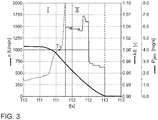
- FIG. 3 a motor diagram is shown, based on which a method according to the invention for the exhaust aftertreatment of the internal combustion engine 10 is explained.
- the engine speed n of the internal combustion engine is shown over the time t.
- a first phase I of the method it is checked whether the rotational speed n of the internal combustion engine 10 is above a threshold value S 1 for the rotational speed n.
- the rotational speed n of the internal combustion engine is set to a rotational speed n above the threshold value S 1 , in particular to a rotational speed of at least 1100 rpm, more preferably from at least 1200 rpm, raised. If the speed n of the internal combustion engine 10 is above the threshold value S 1 , no additional measure takes place.
- the injection of fuel into the combustion chambers 34 of the internal combustion engine 10 is switched off at a time T 1 and the ignition is turned off.
- the particulate mass P pm discharged from the particulate filter 14 or the four-way catalyst 22 is plotted over time t. If the internal combustion engine 10 stops, no further fresh air is conveyed into the exhaust duct 20, so that the regeneration of the particulate filter 14 or of the four-way catalytic converter 22 comes to a standstill.
- the proposed method also protects against uncontrolled Rußabbrand on the particulate filter 14 or the four-way catalyst 22, since the oxygen excess for the oxidation of the soot is always available only for a very limited time period of a few seconds.
- the particulate filter 14 or the four-way catalytic converter 22 is charged again with soot particles, the carbon black entering the particle filter 14 or the four-way catalytic converter 22 a calculation model is determined.
Abstract
Description
- Die Erfindung betrifft eine Vorrichtung sowie ein Verfahren zur Regeneration eines Partikelfilters oder eines Vier-Wege-Katalysators in einer Abgasanlage eines Verbrennungsmotors.
- Die kontinuierliche Verschärfung der Abgasgesetzgebung stellt hohe Anforderungen an die Fahrzeughersteller, welche durch entsprechende Maßnahmen zur Reduktion der motorischen Rohemissionen und durch eine entsprechende Abgasnachbehandlung gelöst werden. Mit Einführung der Gesetzgebungsstufe EU6 wird für Ottomotoren ein Grenzwert für eine Partikelanzahl vorgeschrieben, der in vielen Fällen den Einsatz eines Ottopartikelfilters notwendig macht. Im Fahrbetrieb wird ein solcher Ottopartikelfilter mit Ruß beladen. Damit der Abgasgegendruck nicht zu stark ansteigt, muss dieser Ottopartikelfilter kontinuierlich oder periodisch regeneriert werden. Um eine thermische Oxidation des im Ottopartikelfilter zurückgehaltenen Rußes mit Sauerstoff durchzuführen, ist ein hinreichend hohes Temperaturniveau in Verbindung mit gleichzeitig vorhandenem Sauerstoff in der Abgasanlage des Ottomotors notwendig. Da moderne Ottomotoren normalerweise ohne Sauerstoffüberschuss mit einem stöchiometrischen Verbrennungsluftverhältnis (λ=1) betrieben werden, sind dazu zusätzliche Maßnahmen erforderlich. Dazu kommen als Maßnahmen beispielsweise eine Temperaturerhöhung durch eine Zündwinkelverstellung, eine zeitweise Magerverstellung des Ottomotors, das Einblasen von Sekundärluft in die Abgasanlage oder eine Kombination dieser Maßnahmen infrage. Bevorzugt wird bislang eine Zündwinkelverstellung in Richtung spät in Kombination mit einer Magerverstellung des Ottomotors angewandt, da dieses Verfahren ohne zusätzliche Bauteile auskommt und in den meisten Betriebspunkten des Ottomotors eine ausreichende Sauerstoffmenge liefern kann. Ferner wird angestrebt, die Katalysatoren im Abgaskanal des Verbrennungsmotors nach einem Kaltstart möglichst schnell auf eine Betriebstemperatur zu bringen, um möglichst schnell eine hohe Konvertierungsrate für schädliche Abgaskomponenten zu erreichen. Diese Magerverstellung des Verbrennungsmotors während der Regeneration des Partikelfilters kann jedoch dazu führen, dass es während der Regeneration des Partikelfilter zu einem signifikanten Anstieg der Stickoxid-Emissionen (NOx-Emissionen) kommt, da bei einem überstöchiometrischen Verbrennungsluftverhältnis im Abgas keine Komponenten wie Kohlenstoffmonoxid (CO) oder unverbrannte Kohlenwasserstoffe (HC) mehr enthalten sind, mit denen auf dem Drei-Wege-Katalysator eine katalytische Reduktion der Stickoxid-Emissionen zu molekularem Stickstoff möglich ist.
- Aus der
DE 10 2013 220 899 A1 ist ein Verfahren zur Regeneration eines Partikelfilters in einer Abgasanlage eines Verbrennungsmotors bekannt, wobei die Temperatur des Abgases des Verbrennungsmotors durch eine entsprechende Lambdaregelung angepasst wird, um die für die Regeneration des Partikelfilters notwendige Temperatur sowie ein gleichzeitiges Vorliegen von Restsauerstoff im Abgaskanal des Verbrennungsmotors sicherzustellen. Nachteilig an einem solchen Verfahren ist jedoch, dass es durch die Magerverstellung des Verbrennungsmotors zu einer Erhöhung der Stickoxid-Emissionen im Abgas während der Regeneration des Partikelfilters kommt. - Aus der
WO 2015/169958 A1 ist ein fremdgezündeter Verbrennungsmotor bekannt, in dessen Abgasanlage ein Partikelfilter angeordnet ist, wobei zur Regeneration des Partikelfilters ein mehrstufiges Verfahren durchgeführt wird, um den Fahrkomfort während der Regeneration des Partikelfilters nur so wenig wie möglich zu reduzieren. Dazu wird eine passive Regeneration des Partikelfilters in einer Schubphase des Verbrennungsmotors als "mildeste" Maßnahme mit entsprechenden aktiven Maßnahmen zur Regeneration kombiniert, wobei in einem mehrstufigen Prozess jeweils die Maßnahmen ausgewählt werden, welche mit dem geringsten Eingriff in den Fahrkomfort beziehungsweise die Leistung des Verbrennungsmotors durchgeführt werden können. Nachteilig an einem solchen Verfahren ist jedoch, dass es auch hier bei den aktiven Maßnahmen zu einer Magerverstellung des Verbrennungsluftverhältnisses des Verbrennungsmotors und einem damit verbundenen Anstieg der Stickoxid-Emissionen kommt. - Die
DE 10 2012 022 153 A1 offenbart ein Verfahren zur Regeneration eines Partikelfilters im Abgaskanal eines Ottomotors, wobei in einem ersten Schritt die Temperatur des Partikelfilters oder eines Abgasmassenstroms durch den Partikelfilter bestimmt wird, und bei Erreichen einer Regenerationstemperatur des Partikelfilters der im Partikelfilter zurückgehaltene Ruß oxidiert wird, indem der Sauerstoffanteil im Abgas über ein stöchiometrisches Abgas hinaus erhöht wird. - Aus der
DE 10 2010 046 899 A1 ist eine Regeneration eines Partikelfilters im Abgaskanal eines Verbrennungsmotors bekannt, wobei die Regeneration während der Abschaltung des Verbrennungsmotors erfolgt. Dabei erfolgt eine Verstellung des Verbrennungsluftverhältnisses in Richtung "mager" unmittelbar vor dem Ausschalten der Zündung, wenn der Partikelfilter eine entsprechende Beladung aufweist und die Temperatur das Partikelfilters hoch genug ist, um beim Abschalten des Verbrennungsmotors eine Teil-Regeneration des Partikelfilters zu ermöglichen. Das vorgeschlagene Verfahren ermöglicht jedoch nur die Regeneration einer geringen Teilmenge des im Partikelfilter zurückgehaltenen Rußes, da der Zeitraum, in dem sauerstoffreiche Luft nach Abstellen der Einspritzung und der Zündung in den Abgaskanal gefördert wird, vergleichsweise kurz ist. - Darüber hinaus sind Abgasnachbehandlungssysteme bekannt, bei denen die Temperatur des Partikelfilters durch motorische Maßnahmen, insbesondere durch eine Verstellung des Zündwinkels in Richtung "spät" erhöht wird, bis die Regenerationstemperatur des Partikelfilters erreicht ist, und der zur Oxidation des im Partikelfilter zurückgehaltenen Rußes benötigte Sauerstoff dem Abgaskanal über ein Sekundärluftsystem zugeführt wird. Dazu wird aber stets ein Sekundärluftsystem benötigt, was die Kosten für den Verbrennungsmotor deutlich erhöht.
- Der Erfindung liegt nun die Aufgabe zugrunde, bei einer Abgasanlage ohne Sekundärluftsystem eine zumindest im Wesentlichen emissionsneutrale Regeneration des Partikelfilters zu ermöglichen und die aus dem Stand der Technik bekannten Nachteile zu überwinden.
- Erfindungsgemäß wird diese Aufgabe durch ein Verfahren zur Abgasnachbehandlung eines Verbrennungsmotors, in dessen Abgasanlage ein Partikelfilter oder ein Vier-Wege-Katalysator angeordnet ist, gelöst, welches folgende Schritte umfassend:
- Betreiben des Verbrennungsmotors in einem Normalbetrieb mit stöchiometrischem Verbrennungsluftverhältnis, wobei die bei der Verbrennung entstehenden Rußpartikel in der Abgasanlage durch den Partikelfilter oder den Vier-Wege-Katalysator zurückgehalten werden,
- Ermitteln des Partikeleintrags in den Partikelfilter oder den Vier-Wege-Katalysator durch ein Berechnungsmodell,
- Übermitteln eines Abschaltwunsches des Verbrennungsmotors an ein Steuergerät des Verbrennungsmotors,
- Abschalten der Kraftstoffeinspritzung in die Brennräume des Verbrennungsmotors, wobei die Kraftstoffeinspritzung abgeschaltet wird, wenn die Motordrehzahl des Verbrennungsmotors oberhalb eines Schwellenwertes liegt,
- Regeneration des Partikelfilters oder des Vier-Wege-Katalysators durch den beim Auslauf des Verbrennungsmotors nach Abschaltung der Kraftstoffeinspritzung in die Abgasanlage geförderten Restsauerstoffs, wobei
- der Rußaustrag aus dem Partikelfilter oder dem Vier-Wege-Katalysator durch ein Berechnungsmodell ermittelt wird.
- Bei einem solchen Verfahren kann eine Regeneration des Partikelfilters, insbesondere eine Regeneration in mehreren Teilschritten, erfolgen, ohne dass es während der Regeneration zu einem signifikanten Anstieg der Emissionen, insbesondere der Stickoxidemissionen, kommt. Durch das erfindungsgemäße Verfahren ist keine Magerverstellung des Verbrennungsmotors notwendig. Somit kann eine Abgasreinigung und eine Konvertierung des Schadstoffe durch einen Drei-Wege-Katalysator während des gesamten Motorbetriebs gewährleistet werden, und es nicht notwendig zusätzliche Maßnahmen zur Abgasnachbehandlung während der Regeneration des Partikelfilters zu ergreifen. Durch die Abschaltung der Kraftstoffeinspritzung dreht sich der Verbrennungsmotor aufgrund der Massenträgheit weiter, sodass zwischen dem Zeitpunkt der Abschaltung der Kraftstoffeinspritzung und dem Motorstillstand sauerstoffreiche Luft in den Abgaskanal gefördert wird, mit welcher die im Partikelfilter zurückgehaltenen Rußpartikel oxidiert werden.
- Durch die in den abhängigen Ansprüchen aufgeführten Merkmale sind vorteilhafte Verbesserungen und Weiterbildungen des im unabhängigen Anspruch angegebenen Verfahrens zur Abgasnachbehandlung eines Verbrennungsmotors möglich.
- In bevorzugter Ausgestaltung der Erfindung ist vorgesehen, dass die Drehzahl des Verbrennungsmotors vor dem Abschalten auf eine Drehzahl oberhalb des Schwellenwertes angehoben wird, wenn sich der Verbrennungsmotor zum Zeitpunkt des Abschaltwunsches im Leerlauf befindet. Durch eine Anhebung der Motordrehzahl vor dem Abschalten des Verbrennungsmotors und insbesondere vor dem Abschalten der Kraftstoffeinspritzung in die Brennräume des Verbrennungsmotors kann die Luftmenge gesteigert werden, welche zur Regeneration des Partikelfilters zur Verfügung steht. Dabei wird wiederum die Trägheit des Verbrennungsmotors genutzt, um während des Anhaltevorgangs eine Teilregeneration des Partikelfilters durchzuführen. Geht man von einer Teilbeladung oder vollständigen Beladung des Partikelfilters aus, bevor eine Regeneration des Partikelfilters oder Vier-Wege-Katalysators notwendig ist, so kann durch das vorgeschlagene Verfahren bei jedem Motorstopp eine Teilmenge von 1mg bis 100mg aus dem Partikelfilter ausgetragen werden. Dadurch sind entsprechend viele Teilregenerationen notwendig, welche aber jeweils ohne Zusatzaufwand realisiert werden können und somit für den Fahrer eines Kraftfahrzeuges nicht spürbar sind. Dabei liegt der Schwellenwert für die Motordrehzahl oberhalb der gewöhnlichen Leerlaufdrehzahl des Verbrennungsmotors. Durch eine Anhebung der Drehzahl vor dem Abschalten wird der Auslaufvorgang des Verbrennungsmotors verlängert, wodurch mehr Sauerstoff in die Abgasanlage gefördert wird. Dadurch kann eine größere Teilmenge der Rußpartikel oxidiert werden. Somit sind weniger Regenerationsschritte bis zur vollständigen Regeneration des Partikelfilters notwendig.
- Besonders bevorzugt ist dabei, wenn der Schwellenwert für die Motordrehzahl oberhalb von 900 U/min liegt. Da PKW-Motoren in der Regel eine Leerlaufdrehzahl von 650 U/min bis 900 U/min haben, kann durch einen solchen Schwellenwert sichergestellt werden, dass eine hinreichende Menge an Sauerstoff in den Abgaskanal des Verbrennungsmotors gelangt.
- In weiterer bevorzugter Ausgestaltung des Verfahrens ist vorgesehen, dass die Kraftstoffeinspritzung in die Brennräume des Verbrennungsmotors nur dann abgeschaltet wird, wenn die Temperatur des Partikelfilters oder des Vier-Wege-Katalysators oder die Abgastemperatur oberhalb einer Schwellentemperatur liegt. Die Nutzung des Start/Stopp-Systems für eine aktive Regeneration wird kontinuierlich eingesetzt. Der Motor geht auch in die Stopp-Phase , also Einspritzung aus auch wenn der Filter nicht regeneriert wird. Das wird aus Fahrverhaltenssicht gemacht. Das Fahrzeug muss sich immer gleich verhalten. Zur Regeneration des Partikelfilters, d.h. zur Oxidation der im Partikelfilter oder Vier-Wege-Katalysator zurückgehaltenen Rußpartikel ist neben dem Vorliegen von Sauerstoff zeitgleich eine Mindesttemperatur notwendig, um die Oxidation des Rußes zu ermöglichen. Befinden sich der Partikelfilter oder der Vier-Wege-Katalysator auf einem Temperaturniveau unterhalb dieser Mindesttemperatur, so ist Regeneration des Partikelfilters durch das vorgeschlagenen Verfahren nicht möglich. Daher wird in diesem Betriebszuständen auf das Einleiten des erfindungsgemäßen Verfahrens verzichtet und der Verbrennungsmotor insbesondere ohne eine Anhebung der Drehzahl abgestellt.
- Dabei liegt die Schwellentemperatur vorzugsweise im Bereich zwischen 550°C und 750°C. In diesem Temperaturbereich ist eine Oxidation des im Partikelfilters zurückgehaltenen Rußes ohne die Gefahr einer thermischen Schädigung des Partikelfilters möglich.
- Gemäß einer Verbesserung des vorgeschlagenen Verfahrens ist vorgesehen, dass eine Drosselklappe im Ansaugkanal des Verbrennungsmotors bei einem Abschaltwunsch des Verbrennungsmotors vollständig geöffnet wird. Durch das Öffnen der Drosselklappe kann die dem Abgaskanal zugeführte Luftmenge und somit die Sauerstoffmenge, welche zur Oxidation des im Partikelfilter oder im Vier-Wege-Katalysator zurückgehaltenen Rußes zur Verfügung steht, vergrößert werden. Dadurch kann eine größere Teilmenge der Rußpartikel oxidiert werden. Somit sind weniger Regenerationsschritte bis zur vollständigen Regeneration des Partikelfilters notwendig. Gleichzeitig kann die Oxidation durch eine Stellung der Drosselklappe eingedämmt werden, um den Filter thermisch nicht zu überhitzen. Auch dieses ist optional je nach Projekt anzuwenden.
- In einer bevorzugten Ausführungsform des Verfahrens ist vorgesehen, dass das Abschaltsignal des Verbrennungsmotors durch ein Start-Stopp-System des Verbrennungsmotors getriggert wird. Bei einem Start-Stopp-System erfolgt das Abschalten des Verbrennungsmotors wesentlich häufiger als bei einem Verbrennungsmotor ohne Start-Stopp-System, beispielsweise beim Stopp an einer Ampel. Dadurch wird die Anzahl der Regenerationsphasen erhöht, wodurch die aus dem Partikelfilter ausgetragene Partikelmasse vergrößert werden kann. Bei einem häufigen Start-Stopp-Prozess beispielsweise im Stop- and Go-Verkehr kann somit innerhalb vergleichsweise kurzer Zeit eine im Wesentlichen vollständige Regeneration des Partikelfilters erreicht werden.
- In einer weiteren Verbesserung des Verfahrens ist vorgesehen, dass das Verfahren gestartet wird, wenn die Beladung des Partikelfilters oder des Vier-Wege-Katalysators oberhalb eines Schwellenwertes für die Beladung des Partikelfilters oder des Vier-Wege-Katalysators liegt. Zwar ist es prinzipiell auch möglich, dass Verfahren unabhängig vom Beladungszustand des Partikelfilters oder des Vier-Wege-Katalysators durchzuführen. Jedoch ist die Einleitung des Verfahrens unter Anhebung der Drehzahl des Verbrennungsmotors vor dem Abschaltvorgang besonders vorteilhaft, wenn der Partikelfilter einen ersten Schwellenwert für die Beladung des Partikelfilters oder des Vier-Wege-Katalysators erreicht hat.
- Gemäß einer weiteren, vorteilhaften Ausführungsform des Verfahrens ist vorgesehen, dass bei Erkennen eines zeitnahen Abschaltwunsches des Verbrennungsmotors die Abgastemperatur angehoben wird. Dadurch können der Partikelfilter oder der Vier-Wege-Katalysator auf eine Regenerationstemperatur aufgeheizt werden, sodass der durch das vorgeschlagenen Verfahren in den Abgaskanal eingebrachte Sauerstoff auch ein hinreichende Temperatur zur Oxidation des Rußes vorfindet. Alternativ kann die Temperatur auch dazu angehoben werden, um den Rußabbrand auf dem Partikelfilter zu beschleunigen und in dem zeitliche begrenzten Fenster zwischen Abschaltung der Kraftstoffeinspritzung und Stillstand des Verbrennungsmotors mehr Ruß aus dem Partikelfilter oder dem Vier-Wege-Katalysator auszutragen.
- Erfindungsgemäß wird eine Vorrichtung zur Abgasnachbehandlung eines Verbrennungsmotors mit einer Abgasanlage, in der ein Partikelfilter oder ein Vier-Wege-Katalysator angeordnet ist, sowie mit einem Steuergerät mit einem maschinenlesbaren Programmcode gelöst, wobei das Steuergerät bei einer Ausführung des Programmcodes dazu eingerichtet ist, ein erfindungsgemäßes Verfahren durchzuführen. Durch eine solche Abgasnachbehandlungsvorrichtung ist eine besonders effiziente Abgasreinigung auch in Betriebsphasen, insbesondere bei einer Regeneration des Partikelfilters, möglich, in denen es bei aus dem Stand der Technik bekannten Abgasanlagen zu einem Anstieg der Emissionen kommen kann.
- In einer bevorzugten Ausführungsform der Erfindung ist vorgesehen, dass der Partikelfilter oder der Vier-Wege-Katalysator motornah als erste Komponente der Abgasnachbehandlung angeordnet ist. Durch eine motornahe Anordnung des Partikelfilters oder Vier-Wege-Katalysators kann die Regenerationstemperatur von mindestens 550°C vergleichsweise einfach erreicht werden. Dadurch ist es möglich, die während der Abschaltung des Verbrennungsmotors in den Abgaskanal eingebrachten Frischluft effizient zur Oxidation des im Partikelfilter oder Vier-Wege-Katalysator zurückgehaltenen Rußes zu nutzen. Ist zusätzlich im Abgaskanal des Verbrennungsmotors ein NOx-Speicherkatalysator vorgesehen, so ist es besonders vorteilhaft, wenn der Partikelfilter oder Vier-Wege-Katalysator als erstes Komponente der Abgasnachbehandlung und der NOx-Speicherkatalysator stromabwärts des Partikelfilters oder der Vier-Wege-Katalysators angeordnet ist. Da die maximale Speicherfähigkeit von NOx-Speicherkatalysatoren in einem Temperaturbereich von ca. 250°C bis 480°C, und somit unterhalb der Regenerationstemperatur des Partikelfilters oder des Vier-Wege-Katalysators, liegt, ist es vorteilhaft, wenn das heiße Abgas zunächst den Partikelfilter oder Vier-Wege-Katalysator und dann den NOx-Speicherkatalysator durchströmt, um eine optimale Abgasnachbehandlung und geringstmögliche Emissionen zu erreichen.
- Bevorzugt ist dabei, wenn dem Verbrennungsmotor ein Start-Stopp-System zugeordnet ist, mit welchem der Verbrennungsmotor bei einem Fahrzeugstillstand, beispielsweise bei einem Ampelstopp, angeschaltet wird und bei einem Anfahrwunsch wieder gestartet wird. Verbrennungsmotoren mit Start-Stopp-System weist wesentlich öfter Motorabschaltungen auf, sodass das vorgeschlagenen Verfahren wesentlich öfter eingekoppelt werden kann. Somit ist eine zeitnahe Regeneration des Partikelfilters oder des Vier-Wege-Katalysators möglich.
- Die verschiedenen in dieser Anmeldung genannten Ausführungsformen der Erfindung sind, sofern im Einzelfall nicht anders ausgeführt, mit Vorteil miteinander kombinierbar.
- Die Erfindung wird nachfolgend in Ausführungsbeispielen anhand der zugehörigen Zeichnungen erläutert. Es zeigen:
- Figur 1
- eine Verbrennungsmotor mit einem Ansaugtrakt und einer Abgasanlage, mit welcher die Emissionen während der Regeneration des Partikelfilters in einem erfindungsgemäßen Verfahren reduziert werden können;
- Figur 2
- eine alternative Ausführungsform der erfindungsgemäßen Abgasanlage, bei der anstelle eines Partikelfilters motornah ein Vier-Wege-Katalysator angeordnet ist;
- Figur 3
- ein Diagramm zum Ablauf eines erfindungsgemäßen Verfahrens zur Abgasnachbehandlung eines Verbrennungsmotors.
-
Figur 1 zeigt eine schematische Darstellung eines Verbrennungsmotors 10 mit einer an einem Auslass 32 des Verbrennungsmotors 10 angeschlossenen Abgasanlage 12. In der Abgasanlage 12 ist in Strömungsrichtung eines Abgases des Verbrennungsmotors 10 durch die Abgasanlage 12 motornah ein Partikelfilter 14 angeordnet. Unter einer motornahen Position ist in diesem Zusammenhang eine Position in der Abgasanlage mit einem Abstand von weniger als 80 cm, vorzugsweise von weniger als 50 cm, Abgaslauflänge von dem Auslass 32 des Verbrennungsmotors 10 zu verstehen. Stromabwärts des Partikelfilters 14, insbesondere in einer Unterbodenlage eines Kraftfahrzeuges, sind ein Drei-Wege-Katalysator 16 und weiter stromabwärts ein NOx-Speicherkatalysator 18 angeordnet, welche durch einen Abgaskanal 20 der Abgasanlage 12 miteinander verbunden sind. Die Menge des eingespritzten Kraftstoffes in die Brennräume 34 des Verbrennungsmotors 10 und somit das Verbrennungsluftverhältnis λE des Verbrennungsmotors 10 ist über ein Steuergerät 24 steuerbar. Zur Regelung des Verbrennungsluftverhältnisses λE des Verbrennungsmotors 10 sind im Abgaskanal 20 mehrere Lambdasonden 26, 28, 30 angeordnet. Stromabwärts des Auslasses 32 des Verbrennungsmotors 10 und stromaufwärts des Partikelfilters 14 ist ein Abgasturbolader 42 vorgesehen, dessen Turbine 44 von einem Abgasstrom des Verbrennungsmotors 10 angetrieben wird. Der Verbrennungsmotor 10 weist ferner einen Ansaugtrakt mit einem Ansaugkanal 38 auf, in dem eine Drosselklappe 36 zur Steuerung der den Brennräumen 34 des Verbrennungsmotors 10 zugeführten Luftmenge, angeordnet ist. Ferner ist in dem Ansaugtrakt ein Verdichter 46 angeordnet, welcher durch die Turbine 44 des Abgasturbolader 42 angetrieben wird und die dem Verbrennungsmotor 10 zugeführte Frischluft verdichtet. Dem Verbrennungsmotor 10 ist ein Start-Stopp-System 40 zugeordnet, mit welchem der Verbrennungsmotor 10 bei einem Fahrzeugstillstand abgeschaltet wird und erst auf ein Startsignal, beispielsweise das Lösen des Bremspedals, wieder gestartet wird. - Bei im Wesentlichen gleichem Aufbau wie zu
Figur 1 beschrieben, ist in dem inFigur 2 dargestellten Ausführungsbeispiel der (unbeschichtete) Partikelfilter 14 durch einen Partikelfilter mit einer drei-Wege-katalytisch wirksamen Beschichtung, einem sogenannten Vier-Wege-Katalysator 22 ersetzt. Der Vier-Wege-Katalysator 22 vereint dabei die Funktionen eines Partikelfilters und eines Drei-Wege-Katalysators. Durch die Anordnung des weiteren Drei-Wege-Katalysators 16 in der Unterbodenlage des Kraftfahrzeuges kann der Vier-Wege-Katalysator vergleichsweise klein ausgeführt werden, um eine schnelle Erwärmung auf eine Betriebstemperatur nach einem Kaltstart des Verbrennungsmotors 10 zu ermöglichen. Alternativ kann durch den Vier-Wege-Katalysator 22 auch ein weiterer Drei-Wege-Katalysator 16, insbesondere ein Drei-Wege-Katalysator 16 in Unterbodenlage des Kraftfahrzeuges, entfallen. - Im Betrieb des Verbrennungsmotors 10 werden die bei der Verbrennung auftretenden Partikel im Abgas des Verbrennungsmotors 10 durch den Partikelfilter 14 oder den Vier-Wege-Katalysator 22 zurückgehalten. Dabei wird der Partikelfilter 14 oder der Vier-Wege-Katalysator 22 in bekannter Art und Weise mit Ruß beladen. Infolge der Beladung können Effekte wie ein erhöhter Kraftstoffverbrauch, Leistungsverlust und Zündaussetzer auftreten, wenn der Abgasgegendruck durch die Beladung des Partikelfilters 14 oder des Vier-Wege-Katalysators 22 über einen bestimmten Schwellenwert SL ansteigt. Folglich muss der Partikelfilter 14 oder der Vier-Wege-Katalysator 22 zyklisch oder in Abhängigkeit der Beladung regeneriert werden. Zur Regeneration des Partikelfilters 14 oder des Vier-Wege-Katalysators 22 ist neben dem Erreichen einer Regenerationstemperatur das Vorliegen von Restsauerstoff in der Abgasanlage notwendig, um die im Partikelfilter 14 oder im Vier-Wege-Katalysator 22 zurückgehaltenen Rußpartikel zu oxidieren. Durch den überstöchiometrischen Betrieb des Verbrennungsmotors 10 verlieren der Drei-Wege-Katalysator 16 und der Vier-Wege-Katalysator 22 ihre Konvertierungseigenschaften für Stickoxide, da kein Reduktionsmittel zur Reduktion von Stickoxiden zu elementarem Stickstoff mehr vorhanden ist.
- Um einen überstöchiometrischen Betrieb des Verbrennungsmotors 10 und die damit verbundene Erhöhung der Stickoxidemissionen zu vermeiden, ist vorgesehen, den zur Regeneration des Partikelfilter 14 oder des Vier-Wege-Katalysator 22 notwendigen Sauerstoff in die Abgasanlage zu fördern, indem beim Abschalten des Verbrennungsmotors 10 zunächst die Kraftstoffeinspritzung in die Brennräume 24 des Verbrennungsmotors 10 abgeschaltet wird und die Restdrehzahl des Verbrennungsmotor 10 bis zum Stillstand genutzt wird, um sauerstoffreiche Frischluft in die Abgasanlage 12 zu fördern.
- In
Figur 3 ist ein Motordiagramm dargestellt, anhand dessen ein erfindungsgemäßes Verfahren zur Abgasnachbehandlung des Verbrennungsmotors 10 erläutert wird. Dabei ist die Motordrehzahl n des Verbrennungsmotors über die Zeit t dargestellt. In einer ersten Phase I des Verfahrens wird geprüft, ob die Drehzahl n des Verbrennungsmotors 10 oberhalb eines Schwellenwertes S1 für die Drehzahl n liegt. Liegt die Drehzahl n unterhalb diese Schwellenwertes S1, insbesondere bei der gewöhnlichen Leerlaufdrehzahl nl, so wird zunächst die Drehzahl n des Verbrennungsmotors auf eine Drehzahl n oberhalb des Schwellenwertes S1, insbesondere auf eine Drehzahl von mindestens 1100 U/min, besonders bevorzugt von mindestens 1200 U/min, angehoben. Liegt die Drehzahl n des Verbrennungsmotors 10 oberhalb des Schwellenwertes S1 so erfolgt keine zusätzliche Maßnahme. In einem zweiten Verfahrensschritt wird zu einem Zeitpunkt T1 die Einspritzung von Kraftstoff in die Brennräume 34 des Verbrennungsmotors 10 abgeschaltet und die Zündung abgestellt. Dadurch fällt die Drehzahl n des Verbrennungsmotors 10 von eine Betriebsdrehzahl auf 0 ab, sodass der Verbrennungsmotor 10 zum Stehen kommt. Während des Abschaltens fördert der Verbrennungsmotor durch seine Trägheit bis zum Stillstand Frischluft in den Abgaskanal 20. Dabei stellt sich kurzfristig in einer zweiten Phase II ein Sauerstoffüberschuss λ >>1 in der Abgasanlage 12 ein, sodass der im Partikelfilter 14 oder in dem Vier-Wege-Katalysator 22 zurückgehaltene Ruß oxidert und aus dem Partikelfilter 14 oder dem Vier-Wege-Katalysator 22 in Form von Kohlenstoffdioxid (CO2) ausgetragen wird. Diese Austragung des Rußes erfolgt solange, wie die zur Oxidation des Rußes notwendigen Bedingungen vorliegen. Dabei ist inFigur 3 die aus dem Partikelfilter 14 oder dem Vier-Wege-Katalysator 22 ausgetragene Partikelmasse Ppm über der Zeit t aufgetragen. Kommt der Verbrennungsmotor 10 zu stehen, so wird keine weitere Frischluft in den Abgaskanal 20 gefördert, sodass die Regeneration des Partikelfilter 14 oder des Vier-Wege-Katalysators 22 zum Stillstand kommt. Somit schützt das vorgeschlagenen Verfahren auch vor einem unkontrollierten Rußabbrand auf dem Partikelfilter 14 oder dem Vier-Wege-Katalysator 22, da der Sauerstoffüberschuss zur Oxidation des Rußes immer nur für einen zeitlich sehr begrenzten Zeitraum von wenigen Sekunden zur Verfügung steht. Wird der Verbrennungsmotor 10 nach dem Stillstand des Verbrennungsmotors 10 erneut gestartet, so kommt es zu einer erneuten Beladung des Partikelfilters 14 oder des Vier-Wege-Katalysator 22 mit Rußpartikeln, wobei der Rußeintrag in den Partikelfilter 14 oder den Vier-Wege-Katalysator 22 durch ein Berechnungsmodell ermittelt wird. -
- 10
- Verbrennungsmotor
- 12
- Abgasanlage
- 14
- Partikelfilter
- 16
- Drei-Wege-Katalysator
- 18
- NOx-Speicherkatalysator
- 20
- Abgaskanal
- 22
- Vier-Wege-Katalysator
- 24
- Steuergerät
- 26
- erste Lambdasonde
- 28
- zweite Lambdasonde
- 30
- dritte Lambdasonde
- 32
- Auslass
- 34
- Brennraum
- 36
- Drosselklappe
- 38
- Ansaugkanal
- 40
- Start-Stopp-System
- 42
- Abgasturbolader
- 44
- Turbine
- 46
- Verdichter
- n
- Drehzahl des Verbrennungsmotors
- nA
- Abschaltdrehzahl
- nl
- gewöhnliche Leerlaufdrehzahl
- Ppm
- aus dem Partikelfilter ausgetragene Partikelmasse
- S1
- Schwellenwert
- ST
- Schwellentemperatur
- SL
- Schwellenwert für die Beladung des Partikelfilters
- TEG
- Abgastemperatur
- U/min
- Umdrehungen pro Minute
- λE
- Verbrennungsluftverhältnis des Verbrennungsmotors
Claims (13)
- Verfahren zur Abgasnachbehandlung eines Verbrennungsmotors (10), in dessen Abgasanlage (12) ein Partikelfilter (14) oder ein Vier-Wege-Katalysator (22) angeordnet ist, umfassend folgende Schritte:- Betreiben des Verbrennungsmotors (10) in einem Normalbetrieb mit stöchiometrischem Verbrennungsluftverhältnis, wobei die bei der Verbrennung entstehenden Rußpartikel in der Abgasanlage (12) durch den Partikelfilter (14) oder den Vier-Wege-Katalysator (22) zurückgehalten werden,- Ermitteln des Partikeleintrags in den Partikelfilter (14) oder den Vier-Wege-Katalysator (22) durch ein Berechnungsmodell,- Übermitteln eines Abschaltwunsches des Verbrennungsmotor (10) an ein Steuergerät (24) des Verbrennungsmotors (10),- Abschalten der Kraftstoffeinspritzung in die Brennräume (34) des Verbrennungsmotors (10), wobei die Kraftstoffeinspritzung abgeschaltet wird, wenn die Motordrehzahl (n) des Verbrennungsmotors (10) oberhalb eines Schwellenwertes (S1) liegt,- Regeneration des Partikelfilter (14) oder des Vier-Wege-Katalysators (22) durch den beim Auslauf des Verbrennungsmotors (10) nach Abschaltung der Kraftstoffeinspritzung in die Abgasanlage (12) geförderten Restsauerstoffs, wobei- der Rußaustrag aus dem Partikelfilter (14) oder dem Vier-Wege-Katalysators (22) durch ein Berechnungsmodell ermittelt wird.
- Verfahren zur Abgasnachbehandlung nach Anspruch 1, dadurch gekennzeichnet, dass die Drehzahl (n) des Verbrennungsmotors (10) vor dem Abschalten auf eine Drehzahl (nA) oberhalb des Schwellenwertes (S1) angehoben wird, wenn sich der Verbrennungsmotor (10) zum Zeitpunkt des Abschaltwunsches im Leerlauf befindet.
- Verfahren zur Abgasnachbehandlung nach Anspruch 1 oder 2, dadurch gekennzeichnet, dass der Schwellenwert (S1) der Drehzahl (n) oberhalb der gewöhnlichen Leerlaufdrehzahl (nl) des Verbrennungsmotors (10) liegt.
- Verfahren zur Abgasnachbehandlung nach Anspruch 3, dadurch gekennzeichnet, dass der Schwellenwert (S1) im Bereich von 1100 U/min bis 1800 U/min liegt.
- Verfahren zur Abgasnachbehandlung nach einem der Ansprüche 1 bis 4, dadurch gekennzeichnet, dass die Kraftstoffeinspritzung in die Brennräume (34) des Verbrennungsmotors (10) nur dann abgeschaltet wird, wenn die Temperatur (TPF) des Partikelfilters (14) oder des Vier-Wege-Katalysators (22) oder die Abgastemperatur (TEG) oberhalb einer Schwellentemperatur (ST) befindet.
- Verfahren zur Abgasnachbehandlung nach Anspruch 5, dadurch gekennzeichnet, dass die Schwellentemperatur (ST) im Bereich von 550°C bis 700°C liegt.
- Verfahren zur Abgasnachbehandlung nach einem der Ansprüche 1 bis 6, dadurch gekennzeichnet, dass eine Drosselklappe (36) im Ansaugkanal (38) des Verbrennungsmotors (10) bei dem Abschaltewunsch des Verbrennungsmotors (10) vollständig geöffnet wird.
- Verfahren zur Abgasnachbehandlung nach einem der Ansprüche 1 bis 7, dadurch gekennzeichnet, dass das Abschaltsignal des Verbrennungsmotors (10) durch ein Start-Stopp-System (40) des Verbrennungsmotors (10) getriggert wird.
- Verfahren zur Abgasnachbehandlung nach einem der Ansprüche 1 bis 8, dadurch gekennzeichnet, dass das Verfahren gestartet wird, wenn die Beladung des Partikelfilters (14) oder des Vier-Wege-Katalysators (22) oberhalb eines Schwellenwertes (SL) für die Beladung des Partikelfilters (14) oder des Vier-Wege-Katalysators (22) liegt.
- Verfahren zur Abgasnachbehandlung nach einem der Ansprüche 1 bis 8, dadurch gekennzeichnet, dass bei Erkennen eines zeitnahen Abschaltwunsches des Verbrennungsmotors (10) die Abgastemperatur (TEG) angehoben wird.
- Vorrichtung zur Abgasnachbehandlung eines Verbrennungsmotors (10) mit einer Abgasanlage (12), in der ein Partikelfilter (14) oder ein Vier-Wege-Katalysator (22) angeordnet ist, sowie mit einem Steuergerät (24) mit einem maschinenlesbaren Programmcode, welches bei Ausführung des Programmcodes dazu eingerichtet ist, ein Verfahren nach einem der Ansprüche 1 bis 10 durchzuführen.
- Vorrichtung zur Abgasnachbehandlung nach Anspruch 11, dadurch gekennzeichnet, dass der Partikelfilter (14) oder der Vier-Wege-Katalysator (22) motornah als erste Komponente der Abgasnachbehandlung angeordnet ist.
- Vorrichtung zur Abgasnachbehandlung nach Anspruch 11 oder 12, dadurch gekennzeichnet, dass dem Verbrennungsmotor (10) ein Start-Stopp-System (40) zugeordnet ist.
Applications Claiming Priority (1)
| Application Number | Priority Date | Filing Date | Title |
|---|---|---|---|
| DE102017208438.3A DE102017208438A1 (de) | 2017-05-18 | 2017-05-18 | Regeneration eines Partikelfilters oder Vier-Wege-Katalysators in einer Abgasanlage eines Verbrennungsmotors |
Publications (2)
| Publication Number | Publication Date |
|---|---|
| EP3404228A1 true EP3404228A1 (de) | 2018-11-21 |
| EP3404228B1 EP3404228B1 (de) | 2020-03-18 |
Family
ID=61837633
Family Applications (1)
| Application Number | Title | Priority Date | Filing Date |
|---|---|---|---|
| EP18164849.4A Active EP3404228B1 (de) | 2017-05-18 | 2018-03-29 | Regeneration eines partikelfilters oder vier-wege-katalysators in einer abgasanlage eines verbrennungsmotors |
Country Status (5)
| Country | Link |
|---|---|
| US (1) | US10724457B2 (de) |
| EP (1) | EP3404228B1 (de) |
| KR (1) | KR102021699B1 (de) |
| CN (1) | CN108952896B (de) |
| DE (1) | DE102017208438A1 (de) |
Families Citing this family (4)
| Publication number | Priority date | Publication date | Assignee | Title |
|---|---|---|---|---|
| JP7035749B2 (ja) * | 2018-04-11 | 2022-03-15 | トヨタ自動車株式会社 | 内燃機関の失火検出装置 |
| DE102019202404B4 (de) * | 2019-02-22 | 2024-03-28 | Robert Bosch Gmbh | Verfahren zur Steuerung des Auslaufverhaltens einer Brennkraftmaschine |
| JP2021092205A (ja) * | 2019-12-11 | 2021-06-17 | トヨタ自動車株式会社 | 内燃機関の排気浄化システム |
| CN115773170B (zh) * | 2022-11-25 | 2024-03-26 | 同济大学 | 一种稀燃汽油机NOx排放后处理装置及控制方法 |
Citations (3)
| Publication number | Priority date | Publication date | Assignee | Title |
|---|---|---|---|---|
| US20100089035A1 (en) * | 2007-09-25 | 2010-04-15 | Hitachi Construction Machinery Co., Ltd. | Exhaust gas cleaning system for construction machine |
| US20110072793A1 (en) * | 2009-09-29 | 2011-03-31 | Ford Global Technologies, Llc | Particulate filter regeneration in an engine |
| US20160201534A1 (en) * | 2015-01-12 | 2016-07-14 | Ford Global Technologies, Llc | Emission control device regeneration |
Family Cites Families (18)
| Publication number | Priority date | Publication date | Assignee | Title |
|---|---|---|---|---|
| DE10130633B4 (de) * | 2001-06-26 | 2010-10-21 | Man Nutzfahrzeuge Ag | Verfahren zur Regenerierung eines Partikelfilters |
| SE522146C2 (sv) * | 2002-05-07 | 2004-01-20 | Volvo Lastvagnar Ab | Metod för regenerering av ett partikelfilter vid motorbromsning samt fordon i vilket en sådan metod utnyttjas |
| JP4075573B2 (ja) * | 2002-06-13 | 2008-04-16 | 株式会社デンソー | 内燃機関の排ガス浄化装置 |
| JP2010038147A (ja) | 2008-07-10 | 2010-02-18 | Toyota Motor Corp | エンジンの排気浄化システム |
| US8516797B2 (en) * | 2009-09-29 | 2013-08-27 | Ford Global Technologies, Llc | Control of exhaust flow in an engine including a particulate filter |
| US8424295B2 (en) | 2009-09-29 | 2013-04-23 | Ford Global Technologies, Llc | Particulate filter regeneration during engine shutdown |
| US8875494B2 (en) * | 2009-09-29 | 2014-11-04 | Ford Global Technologies, Llc | Fuel control for spark ignited engine having a particulate filter system |
| JP5325249B2 (ja) * | 2011-03-18 | 2013-10-23 | 株式会社小松製作所 | 粒子状物質堆積量推定装置、排気ガス浄化システム、および粒子状物質堆積量推定方法 |
| KR101272944B1 (ko) * | 2011-09-29 | 2013-06-11 | 기아자동차주식회사 | 가솔린 엔진의 수트 재생 시스템 및 방법 |
| DE102012202188A1 (de) | 2012-02-14 | 2013-08-14 | Robert Bosch Gmbh | Dosiermodul zum Einbringen eines flüssigen Stoffes in das Abgas einer Brennkraftmaschine |
| DE102012022153B4 (de) | 2012-11-10 | 2019-01-24 | Volkswagen Aktiengesellschaft | Verfahren zur Regeneration mindestens eines Partikelfilters, Steuereinrichtung und Kraftfahrzeug mit einer solchen |
| DE102013008426A1 (de) | 2013-05-16 | 2014-11-20 | Volkswagen Aktiengesellschaft | Verfahren zur Ermittlung einer Rußbeladung eines Partikelfilters, Steuereinheit sowie Kraftfahrzeug |
| DE102013220899A1 (de) | 2013-10-15 | 2015-04-16 | Continental Automotive Gmbh | Regeneration eines Partikelfilters einer Abgasnachbehandlungsanlage für eine Brennkraftmaschine mit einer Lambda-Regelung |
| DE102014006692A1 (de) | 2014-05-09 | 2015-11-12 | Fev Gmbh | Ottomotor mit Partikelfilter und Regenerationsstrategie und Verfahren hierzu |
| US9284920B2 (en) * | 2014-06-19 | 2016-03-15 | Ford Global Technologies, Llc | Systems and methods for stopping and starting an engine with dedicated EGR |
| DE102015208631A1 (de) * | 2015-05-08 | 2016-11-10 | Volkswagen Aktiengesellschaft | Verfahren zum Regenerieren eines Ottopartikelfilters einer fremdgezündeten Brennkraftmaschine und Steuerungseinheit einer fremdgezündeten Brennkraftmaschine |
| DE102015211570A1 (de) * | 2015-06-23 | 2016-12-29 | Ford Global Technologies, Llc | Regeneration von Partikelfiltern in einem Hybridantriebsstrang |
| US10473011B2 (en) * | 2016-10-04 | 2019-11-12 | Ford Global Technologies, Llc | Particulate filter regeneration system and method |
-
2017
- 2017-05-18 DE DE102017208438.3A patent/DE102017208438A1/de not_active Withdrawn
-
2018
- 2018-03-29 EP EP18164849.4A patent/EP3404228B1/de active Active
- 2018-05-15 KR KR1020180055225A patent/KR102021699B1/ko active IP Right Grant
- 2018-05-18 CN CN201810480424.0A patent/CN108952896B/zh active Active
- 2018-05-18 US US15/983,720 patent/US10724457B2/en active Active
Patent Citations (3)
| Publication number | Priority date | Publication date | Assignee | Title |
|---|---|---|---|---|
| US20100089035A1 (en) * | 2007-09-25 | 2010-04-15 | Hitachi Construction Machinery Co., Ltd. | Exhaust gas cleaning system for construction machine |
| US20110072793A1 (en) * | 2009-09-29 | 2011-03-31 | Ford Global Technologies, Llc | Particulate filter regeneration in an engine |
| US20160201534A1 (en) * | 2015-01-12 | 2016-07-14 | Ford Global Technologies, Llc | Emission control device regeneration |
Also Published As
| Publication number | Publication date |
|---|---|
| KR102021699B1 (ko) | 2019-09-16 |
| US10724457B2 (en) | 2020-07-28 |
| CN108952896B (zh) | 2021-07-13 |
| KR20180127207A (ko) | 2018-11-28 |
| EP3404228B1 (de) | 2020-03-18 |
| DE102017208438A1 (de) | 2018-11-22 |
| US20180334976A1 (en) | 2018-11-22 |
| CN108952896A (zh) | 2018-12-07 |
Similar Documents
| Publication | Publication Date | Title |
|---|---|---|
| EP3642460B1 (de) | Abgasnachbehandlungssystem sowie verfahren zur abgasnachbehandlung eines verbrennungsmotors | |
| EP3475543B1 (de) | Verfahren und vorrichtung zur abgasnachbehandlung eines verbrennungsmotors | |
| EP3115566B1 (de) | Verfahren zur abgasnachbehandlung einer brennkraftmaschine | |
| EP3502428B1 (de) | Abgasnachbehandlungssystem und verfahren zur abgasnachbehandlung eines verbrennungsmotors | |
| DE102015212514B4 (de) | Verfahren zur Abgasnachbehandlung und Vorrichtung zur Reinigung des Abgases einer Brennkraftmaschine | |
| EP1121513B1 (de) | Verfahren zur stickoxidreduzierung im abgas einer mager betriebenen brennkraftmaschine | |
| EP3404228B1 (de) | Regeneration eines partikelfilters oder vier-wege-katalysators in einer abgasanlage eines verbrennungsmotors | |
| DE102011100677A1 (de) | Betriebsverfahren für einen Kraftfahrzeug-Dieselmotor | |
| EP3508704A1 (de) | Abgasnachbehandlungssystem und verfahren zur abgasnachbehandlung eines verbrennungsmotors | |
| EP3523515B1 (de) | Verfahren zur regeneration eines partikelfilters sowie kraftfahrzeug mit einem partikelfilter | |
| WO2018134151A1 (de) | Regeneration eines partikelfilters oder vier-wege-katalysators in einer abgasanlage eines verbrennungsmotors | |
| EP3412880A1 (de) | Verfahren zum regenerieren eines partikelfilters in der abgasanlage eines verbrennungsmotors sowie verbrennungsmotor | |
| DE102017101177A1 (de) | Verfahren zur Regeneration eines Partikelfilters sowie Abgasnachbehandlungsvorrichtung mit einem Partikelfilter | |
| DE102017103560B4 (de) | Verbrennungsmotor und Verfahren zur Regeneration eines Partikelfilters im Abgaskanal eines Verbrennungsmotors | |
| DE102016112657A1 (de) | Verfahren und Vorrichtung zur Abgasnachbehandlung eines Verbrennungsmotors | |
| DE102017115399A1 (de) | Abgasnachbehandlungssystem und Verfahren zur Abgasnachbehandlung eines Verbrennungsmotors | |
| WO2007147720A1 (de) | Verfahren zum betreiben einer in einem abgasbereich einer brennkraftmaschine angeordneten abgasreinigungsanlage | |
| EP3667056B1 (de) | Abgasnachbehandlung eines verbrennungsmotors | |
| EP3770386B1 (de) | Abgasnachbehandlungssystem und verfahren zur abgasnachbehandlung eines verbrennungsmotors | |
| DE102019219906B4 (de) | Verfahren und Vorrichtung zum Aufheizen eines im Abgastrakt eines Kraftfahrzeugs angeordneten Katalysators mittels geregelter Sekundärluft | |
| DE102016119211A1 (de) | Vorrichtung und Verfahren zur Abgasnachbehandlung eines Verbrennungsmotors | |
| DE102017208671A1 (de) | Verfahren zur Abgasnachbehandlung eines Verbrennungsmotors sowie Abgasnachbehandlungssystem | |
| WO2020069550A1 (de) | Verfahren und ottomotoranordnung mit einer verbesserten abgasnachbehandlung durch eine schubabschaltungsstrategie | |
| EP1563178B1 (de) | Verfahren zum betreiben einer brennkraftmaschine eines fahrzeugs, insbesondere eines kraftfahrzeuges | |
| DE102017210880A1 (de) | Verfahren zum Aufheizen eines Katalysators in einer Abgasanlage eines Verbrennungsmotors sowie Abgasnachbehandlungssystem |
Legal Events
| Date | Code | Title | Description |
|---|---|---|---|
| PUAI | Public reference made under article 153(3) epc to a published international application that has entered the european phase |
Free format text: ORIGINAL CODE: 0009012 |
|
| STAA | Information on the status of an ep patent application or granted ep patent |
Free format text: STATUS: THE APPLICATION HAS BEEN PUBLISHED |
|
| AK | Designated contracting states |
Kind code of ref document: A1 Designated state(s): AL AT BE BG CH CY CZ DE DK EE ES FI FR GB GR HR HU IE IS IT LI LT LU LV MC MK MT NL NO PL PT RO RS SE SI SK SM TR |
|
| AX | Request for extension of the european patent |
Extension state: BA ME |
|
| STAA | Information on the status of an ep patent application or granted ep patent |
Free format text: STATUS: REQUEST FOR EXAMINATION WAS MADE |
|
| 17P | Request for examination filed |
Effective date: 20190521 |
|
| RBV | Designated contracting states (corrected) |
Designated state(s): AL AT BE BG CH CY CZ DE DK EE ES FI FR GB GR HR HU IE IS IT LI LT LU LV MC MK MT NL NO PL PT RO RS SE SI SK SM TR |
|
| RIC1 | Information provided on ipc code assigned before grant |
Ipc: F02D 41/02 20060101ALI20190731BHEP Ipc: F01N 3/023 20060101ALI20190731BHEP Ipc: F01N 9/00 20060101AFI20190731BHEP |
|
| GRAP | Despatch of communication of intention to grant a patent |
Free format text: ORIGINAL CODE: EPIDOSNIGR1 |
|
| STAA | Information on the status of an ep patent application or granted ep patent |
Free format text: STATUS: GRANT OF PATENT IS INTENDED |
|
| INTG | Intention to grant announced |
Effective date: 20191004 |
|
| GRAS | Grant fee paid |
Free format text: ORIGINAL CODE: EPIDOSNIGR3 |
|
| GRAA | (expected) grant |
Free format text: ORIGINAL CODE: 0009210 |
|
| STAA | Information on the status of an ep patent application or granted ep patent |
Free format text: STATUS: THE PATENT HAS BEEN GRANTED |
|
| AK | Designated contracting states |
Kind code of ref document: B1 Designated state(s): AL AT BE BG CH CY CZ DE DK EE ES FI FR GB GR HR HU IE IS IT LI LT LU LV MC MK MT NL NO PL PT RO RS SE SI SK SM TR |
|
| REG | Reference to a national code |
Ref country code: GB Ref legal event code: FG4D Free format text: NOT ENGLISH |
|
| REG | Reference to a national code |
Ref country code: DE Ref legal event code: R096 Ref document number: 502018000960 Country of ref document: DE |
|
| REG | Reference to a national code |
Ref country code: AT Ref legal event code: REF Ref document number: 1246143 Country of ref document: AT Kind code of ref document: T Effective date: 20200415 Ref country code: IE Ref legal event code: FG4D Free format text: LANGUAGE OF EP DOCUMENT: GERMAN |
|
| PG25 | Lapsed in a contracting state [announced via postgrant information from national office to epo] |
Ref country code: RS Free format text: LAPSE BECAUSE OF FAILURE TO SUBMIT A TRANSLATION OF THE DESCRIPTION OR TO PAY THE FEE WITHIN THE PRESCRIBED TIME-LIMIT Effective date: 20200318 Ref country code: FI Free format text: LAPSE BECAUSE OF FAILURE TO SUBMIT A TRANSLATION OF THE DESCRIPTION OR TO PAY THE FEE WITHIN THE PRESCRIBED TIME-LIMIT Effective date: 20200318 Ref country code: NO Free format text: LAPSE BECAUSE OF FAILURE TO SUBMIT A TRANSLATION OF THE DESCRIPTION OR TO PAY THE FEE WITHIN THE PRESCRIBED TIME-LIMIT Effective date: 20200618 |
|
| REG | Reference to a national code |
Ref country code: NL Ref legal event code: MP Effective date: 20200318 |
|
| PG25 | Lapsed in a contracting state [announced via postgrant information from national office to epo] |
Ref country code: HR Free format text: LAPSE BECAUSE OF FAILURE TO SUBMIT A TRANSLATION OF THE DESCRIPTION OR TO PAY THE FEE WITHIN THE PRESCRIBED TIME-LIMIT Effective date: 20200318 Ref country code: GR Free format text: LAPSE BECAUSE OF FAILURE TO SUBMIT A TRANSLATION OF THE DESCRIPTION OR TO PAY THE FEE WITHIN THE PRESCRIBED TIME-LIMIT Effective date: 20200619 Ref country code: LV Free format text: LAPSE BECAUSE OF FAILURE TO SUBMIT A TRANSLATION OF THE DESCRIPTION OR TO PAY THE FEE WITHIN THE PRESCRIBED TIME-LIMIT Effective date: 20200318 Ref country code: SE Free format text: LAPSE BECAUSE OF FAILURE TO SUBMIT A TRANSLATION OF THE DESCRIPTION OR TO PAY THE FEE WITHIN THE PRESCRIBED TIME-LIMIT Effective date: 20200318 Ref country code: BG Free format text: LAPSE BECAUSE OF FAILURE TO SUBMIT A TRANSLATION OF THE DESCRIPTION OR TO PAY THE FEE WITHIN THE PRESCRIBED TIME-LIMIT Effective date: 20200618 |
|
| REG | Reference to a national code |
Ref country code: LT Ref legal event code: MG4D |
|
| PG25 | Lapsed in a contracting state [announced via postgrant information from national office to epo] |
Ref country code: NL Free format text: LAPSE BECAUSE OF FAILURE TO SUBMIT A TRANSLATION OF THE DESCRIPTION OR TO PAY THE FEE WITHIN THE PRESCRIBED TIME-LIMIT Effective date: 20200318 |
|
| PG25 | Lapsed in a contracting state [announced via postgrant information from national office to epo] |
Ref country code: RO Free format text: LAPSE BECAUSE OF FAILURE TO SUBMIT A TRANSLATION OF THE DESCRIPTION OR TO PAY THE FEE WITHIN THE PRESCRIBED TIME-LIMIT Effective date: 20200318 Ref country code: CZ Free format text: LAPSE BECAUSE OF FAILURE TO SUBMIT A TRANSLATION OF THE DESCRIPTION OR TO PAY THE FEE WITHIN THE PRESCRIBED TIME-LIMIT Effective date: 20200318 Ref country code: SK Free format text: LAPSE BECAUSE OF FAILURE TO SUBMIT A TRANSLATION OF THE DESCRIPTION OR TO PAY THE FEE WITHIN THE PRESCRIBED TIME-LIMIT Effective date: 20200318 Ref country code: IS Free format text: LAPSE BECAUSE OF FAILURE TO SUBMIT A TRANSLATION OF THE DESCRIPTION OR TO PAY THE FEE WITHIN THE PRESCRIBED TIME-LIMIT Effective date: 20200718 Ref country code: LT Free format text: LAPSE BECAUSE OF FAILURE TO SUBMIT A TRANSLATION OF THE DESCRIPTION OR TO PAY THE FEE WITHIN THE PRESCRIBED TIME-LIMIT Effective date: 20200318 Ref country code: PT Free format text: LAPSE BECAUSE OF FAILURE TO SUBMIT A TRANSLATION OF THE DESCRIPTION OR TO PAY THE FEE WITHIN THE PRESCRIBED TIME-LIMIT Effective date: 20200812 Ref country code: SM Free format text: LAPSE BECAUSE OF FAILURE TO SUBMIT A TRANSLATION OF THE DESCRIPTION OR TO PAY THE FEE WITHIN THE PRESCRIBED TIME-LIMIT Effective date: 20200318 Ref country code: EE Free format text: LAPSE BECAUSE OF FAILURE TO SUBMIT A TRANSLATION OF THE DESCRIPTION OR TO PAY THE FEE WITHIN THE PRESCRIBED TIME-LIMIT Effective date: 20200318 |
|
| REG | Reference to a national code |
Ref country code: DE Ref legal event code: R097 Ref document number: 502018000960 Country of ref document: DE |
|
| REG | Reference to a national code |
Ref country code: BE Ref legal event code: MM Effective date: 20200331 |
|
| PG25 | Lapsed in a contracting state [announced via postgrant information from national office to epo] |
Ref country code: MC Free format text: LAPSE BECAUSE OF FAILURE TO SUBMIT A TRANSLATION OF THE DESCRIPTION OR TO PAY THE FEE WITHIN THE PRESCRIBED TIME-LIMIT Effective date: 20200318 Ref country code: LU Free format text: LAPSE BECAUSE OF NON-PAYMENT OF DUE FEES Effective date: 20200329 |
|
| PLBE | No opposition filed within time limit |
Free format text: ORIGINAL CODE: 0009261 |
|
| STAA | Information on the status of an ep patent application or granted ep patent |
Free format text: STATUS: NO OPPOSITION FILED WITHIN TIME LIMIT |
|
| PG25 | Lapsed in a contracting state [announced via postgrant information from national office to epo] |
Ref country code: DK Free format text: LAPSE BECAUSE OF FAILURE TO SUBMIT A TRANSLATION OF THE DESCRIPTION OR TO PAY THE FEE WITHIN THE PRESCRIBED TIME-LIMIT Effective date: 20200318 Ref country code: ES Free format text: LAPSE BECAUSE OF FAILURE TO SUBMIT A TRANSLATION OF THE DESCRIPTION OR TO PAY THE FEE WITHIN THE PRESCRIBED TIME-LIMIT Effective date: 20200318 Ref country code: IT Free format text: LAPSE BECAUSE OF FAILURE TO SUBMIT A TRANSLATION OF THE DESCRIPTION OR TO PAY THE FEE WITHIN THE PRESCRIBED TIME-LIMIT Effective date: 20200318 Ref country code: IE Free format text: LAPSE BECAUSE OF NON-PAYMENT OF DUE FEES Effective date: 20200329 |
|
| 26N | No opposition filed |
Effective date: 20201221 |
|
| PG25 | Lapsed in a contracting state [announced via postgrant information from national office to epo] |
Ref country code: BE Free format text: LAPSE BECAUSE OF NON-PAYMENT OF DUE FEES Effective date: 20200331 Ref country code: PL Free format text: LAPSE BECAUSE OF FAILURE TO SUBMIT A TRANSLATION OF THE DESCRIPTION OR TO PAY THE FEE WITHIN THE PRESCRIBED TIME-LIMIT Effective date: 20200318 |
|
| PG25 | Lapsed in a contracting state [announced via postgrant information from national office to epo] |
Ref country code: SI Free format text: LAPSE BECAUSE OF FAILURE TO SUBMIT A TRANSLATION OF THE DESCRIPTION OR TO PAY THE FEE WITHIN THE PRESCRIBED TIME-LIMIT Effective date: 20200318 |
|
| REG | Reference to a national code |
Ref country code: CH Ref legal event code: PL |
|
| PG25 | Lapsed in a contracting state [announced via postgrant information from national office to epo] |
Ref country code: CH Free format text: LAPSE BECAUSE OF NON-PAYMENT OF DUE FEES Effective date: 20210331 Ref country code: LI Free format text: LAPSE BECAUSE OF NON-PAYMENT OF DUE FEES Effective date: 20210331 |
|
| PG25 | Lapsed in a contracting state [announced via postgrant information from national office to epo] |
Ref country code: TR Free format text: LAPSE BECAUSE OF FAILURE TO SUBMIT A TRANSLATION OF THE DESCRIPTION OR TO PAY THE FEE WITHIN THE PRESCRIBED TIME-LIMIT Effective date: 20200318 Ref country code: MT Free format text: LAPSE BECAUSE OF FAILURE TO SUBMIT A TRANSLATION OF THE DESCRIPTION OR TO PAY THE FEE WITHIN THE PRESCRIBED TIME-LIMIT Effective date: 20200318 Ref country code: CY Free format text: LAPSE BECAUSE OF FAILURE TO SUBMIT A TRANSLATION OF THE DESCRIPTION OR TO PAY THE FEE WITHIN THE PRESCRIBED TIME-LIMIT Effective date: 20200318 |
|
| PG25 | Lapsed in a contracting state [announced via postgrant information from national office to epo] |
Ref country code: MK Free format text: LAPSE BECAUSE OF FAILURE TO SUBMIT A TRANSLATION OF THE DESCRIPTION OR TO PAY THE FEE WITHIN THE PRESCRIBED TIME-LIMIT Effective date: 20200318 Ref country code: AL Free format text: LAPSE BECAUSE OF FAILURE TO SUBMIT A TRANSLATION OF THE DESCRIPTION OR TO PAY THE FEE WITHIN THE PRESCRIBED TIME-LIMIT Effective date: 20200318 |
|
| PGFP | Annual fee paid to national office [announced via postgrant information from national office to epo] |
Ref country code: FR Payment date: 20230323 Year of fee payment: 6 |
|
| PGFP | Annual fee paid to national office [announced via postgrant information from national office to epo] |
Ref country code: GB Payment date: 20230321 Year of fee payment: 6 Ref country code: DE Payment date: 20230331 Year of fee payment: 6 |
|
| P01 | Opt-out of the competence of the unified patent court (upc) registered |
Effective date: 20230523 |