EP3404226A1 - Catalyst deterioration detecting system and catalyst deterioration detecting method - Google Patents
Catalyst deterioration detecting system and catalyst deterioration detecting method Download PDFInfo
- Publication number
- EP3404226A1 EP3404226A1 EP17836835.3A EP17836835A EP3404226A1 EP 3404226 A1 EP3404226 A1 EP 3404226A1 EP 17836835 A EP17836835 A EP 17836835A EP 3404226 A1 EP3404226 A1 EP 3404226A1
- Authority
- EP
- European Patent Office
- Prior art keywords
- temperature
- detection means
- catalyst
- temperature detection
- downstream
- Prior art date
- Legal status (The legal status is an assumption and is not a legal conclusion. Google has not performed a legal analysis and makes no representation as to the accuracy of the status listed.)
- Granted
Links
Images


Classifications
-
- F—MECHANICAL ENGINEERING; LIGHTING; HEATING; WEAPONS; BLASTING
- F01—MACHINES OR ENGINES IN GENERAL; ENGINE PLANTS IN GENERAL; STEAM ENGINES
- F01N—GAS-FLOW SILENCERS OR EXHAUST APPARATUS FOR MACHINES OR ENGINES IN GENERAL; GAS-FLOW SILENCERS OR EXHAUST APPARATUS FOR INTERNAL-COMBUSTION ENGINES
- F01N11/00—Monitoring or diagnostic devices for exhaust-gas treatment apparatus
- F01N11/002—Monitoring or diagnostic devices for exhaust-gas treatment apparatus the diagnostic devices measuring or estimating temperature or pressure in, or downstream of the exhaust apparatus
-
- B—PERFORMING OPERATIONS; TRANSPORTING
- B01—PHYSICAL OR CHEMICAL PROCESSES OR APPARATUS IN GENERAL
- B01D—SEPARATION
- B01D53/00—Separation of gases or vapours; Recovering vapours of volatile solvents from gases; Chemical or biological purification of waste gases, e.g. engine exhaust gases, smoke, fumes, flue gases, aerosols
- B01D53/34—Chemical or biological purification of waste gases
- B01D53/92—Chemical or biological purification of waste gases of engine exhaust gases
- B01D53/94—Chemical or biological purification of waste gases of engine exhaust gases by catalytic processes
-
- F—MECHANICAL ENGINEERING; LIGHTING; HEATING; WEAPONS; BLASTING
- F01—MACHINES OR ENGINES IN GENERAL; ENGINE PLANTS IN GENERAL; STEAM ENGINES
- F01N—GAS-FLOW SILENCERS OR EXHAUST APPARATUS FOR MACHINES OR ENGINES IN GENERAL; GAS-FLOW SILENCERS OR EXHAUST APPARATUS FOR INTERNAL-COMBUSTION ENGINES
- F01N3/00—Exhaust or silencing apparatus having means for purifying, rendering innocuous, or otherwise treating exhaust
-
- F—MECHANICAL ENGINEERING; LIGHTING; HEATING; WEAPONS; BLASTING
- F01—MACHINES OR ENGINES IN GENERAL; ENGINE PLANTS IN GENERAL; STEAM ENGINES
- F01N—GAS-FLOW SILENCERS OR EXHAUST APPARATUS FOR MACHINES OR ENGINES IN GENERAL; GAS-FLOW SILENCERS OR EXHAUST APPARATUS FOR INTERNAL-COMBUSTION ENGINES
- F01N3/00—Exhaust or silencing apparatus having means for purifying, rendering innocuous, or otherwise treating exhaust
- F01N3/08—Exhaust or silencing apparatus having means for purifying, rendering innocuous, or otherwise treating exhaust for rendering innocuous
- F01N3/10—Exhaust or silencing apparatus having means for purifying, rendering innocuous, or otherwise treating exhaust for rendering innocuous by thermal or catalytic conversion of noxious components of exhaust
- F01N3/101—Three-way catalysts
-
- F—MECHANICAL ENGINEERING; LIGHTING; HEATING; WEAPONS; BLASTING
- F01—MACHINES OR ENGINES IN GENERAL; ENGINE PLANTS IN GENERAL; STEAM ENGINES
- F01N—GAS-FLOW SILENCERS OR EXHAUST APPARATUS FOR MACHINES OR ENGINES IN GENERAL; GAS-FLOW SILENCERS OR EXHAUST APPARATUS FOR INTERNAL-COMBUSTION ENGINES
- F01N3/00—Exhaust or silencing apparatus having means for purifying, rendering innocuous, or otherwise treating exhaust
- F01N3/08—Exhaust or silencing apparatus having means for purifying, rendering innocuous, or otherwise treating exhaust for rendering innocuous
- F01N3/10—Exhaust or silencing apparatus having means for purifying, rendering innocuous, or otherwise treating exhaust for rendering innocuous by thermal or catalytic conversion of noxious components of exhaust
- F01N3/103—Oxidation catalysts for HC and CO only
-
- F—MECHANICAL ENGINEERING; LIGHTING; HEATING; WEAPONS; BLASTING
- F01—MACHINES OR ENGINES IN GENERAL; ENGINE PLANTS IN GENERAL; STEAM ENGINES
- F01N—GAS-FLOW SILENCERS OR EXHAUST APPARATUS FOR MACHINES OR ENGINES IN GENERAL; GAS-FLOW SILENCERS OR EXHAUST APPARATUS FOR INTERNAL-COMBUSTION ENGINES
- F01N3/00—Exhaust or silencing apparatus having means for purifying, rendering innocuous, or otherwise treating exhaust
- F01N3/08—Exhaust or silencing apparatus having means for purifying, rendering innocuous, or otherwise treating exhaust for rendering innocuous
- F01N3/10—Exhaust or silencing apparatus having means for purifying, rendering innocuous, or otherwise treating exhaust for rendering innocuous by thermal or catalytic conversion of noxious components of exhaust
- F01N3/18—Exhaust or silencing apparatus having means for purifying, rendering innocuous, or otherwise treating exhaust for rendering innocuous by thermal or catalytic conversion of noxious components of exhaust characterised by methods of operation; Control
- F01N3/20—Exhaust or silencing apparatus having means for purifying, rendering innocuous, or otherwise treating exhaust for rendering innocuous by thermal or catalytic conversion of noxious components of exhaust characterised by methods of operation; Control specially adapted for catalytic conversion
-
- F—MECHANICAL ENGINEERING; LIGHTING; HEATING; WEAPONS; BLASTING
- F02—COMBUSTION ENGINES; HOT-GAS OR COMBUSTION-PRODUCT ENGINE PLANTS
- F02D—CONTROLLING COMBUSTION ENGINES
- F02D45/00—Electrical control not provided for in groups F02D41/00 - F02D43/00
-
- G—PHYSICS
- G01—MEASURING; TESTING
- G01K—MEASURING TEMPERATURE; MEASURING QUANTITY OF HEAT; THERMALLY-SENSITIVE ELEMENTS NOT OTHERWISE PROVIDED FOR
- G01K1/00—Details of thermometers not specially adapted for particular types of thermometer
- G01K1/14—Supports; Fastening devices; Arrangements for mounting thermometers in particular locations
-
- G—PHYSICS
- G01—MEASURING; TESTING
- G01K—MEASURING TEMPERATURE; MEASURING QUANTITY OF HEAT; THERMALLY-SENSITIVE ELEMENTS NOT OTHERWISE PROVIDED FOR
- G01K7/00—Measuring temperature based on the use of electric or magnetic elements directly sensitive to heat ; Power supply therefor, e.g. using thermoelectric elements
- G01K7/02—Measuring temperature based on the use of electric or magnetic elements directly sensitive to heat ; Power supply therefor, e.g. using thermoelectric elements using thermoelectric elements, e.g. thermocouples
-
- G—PHYSICS
- G01—MEASURING; TESTING
- G01K—MEASURING TEMPERATURE; MEASURING QUANTITY OF HEAT; THERMALLY-SENSITIVE ELEMENTS NOT OTHERWISE PROVIDED FOR
- G01K7/00—Measuring temperature based on the use of electric or magnetic elements directly sensitive to heat ; Power supply therefor, e.g. using thermoelectric elements
- G01K7/02—Measuring temperature based on the use of electric or magnetic elements directly sensitive to heat ; Power supply therefor, e.g. using thermoelectric elements using thermoelectric elements, e.g. thermocouples
- G01K7/04—Measuring temperature based on the use of electric or magnetic elements directly sensitive to heat ; Power supply therefor, e.g. using thermoelectric elements using thermoelectric elements, e.g. thermocouples the object to be measured not forming one of the thermoelectric materials
- G01K7/06—Measuring temperature based on the use of electric or magnetic elements directly sensitive to heat ; Power supply therefor, e.g. using thermoelectric elements using thermoelectric elements, e.g. thermocouples the object to be measured not forming one of the thermoelectric materials the thermoelectric materials being arranged one within the other with the junction at one end exposed to the object, e.g. sheathed type
-
- G—PHYSICS
- G01—MEASURING; TESTING
- G01N—INVESTIGATING OR ANALYSING MATERIALS BY DETERMINING THEIR CHEMICAL OR PHYSICAL PROPERTIES
- G01N25/00—Investigating or analyzing materials by the use of thermal means
- G01N25/72—Investigating presence of flaws
-
- B—PERFORMING OPERATIONS; TRANSPORTING
- B01—PHYSICAL OR CHEMICAL PROCESSES OR APPARATUS IN GENERAL
- B01D—SEPARATION
- B01D53/00—Separation of gases or vapours; Recovering vapours of volatile solvents from gases; Chemical or biological purification of waste gases, e.g. engine exhaust gases, smoke, fumes, flue gases, aerosols
- B01D53/34—Chemical or biological purification of waste gases
- B01D53/92—Chemical or biological purification of waste gases of engine exhaust gases
- B01D53/94—Chemical or biological purification of waste gases of engine exhaust gases by catalytic processes
- B01D53/9445—Simultaneously removing carbon monoxide, hydrocarbons or nitrogen oxides making use of three-way catalysts [TWC] or four-way-catalysts [FWC]
-
- F—MECHANICAL ENGINEERING; LIGHTING; HEATING; WEAPONS; BLASTING
- F01—MACHINES OR ENGINES IN GENERAL; ENGINE PLANTS IN GENERAL; STEAM ENGINES
- F01N—GAS-FLOW SILENCERS OR EXHAUST APPARATUS FOR MACHINES OR ENGINES IN GENERAL; GAS-FLOW SILENCERS OR EXHAUST APPARATUS FOR INTERNAL-COMBUSTION ENGINES
- F01N2550/00—Monitoring or diagnosing the deterioration of exhaust systems
- F01N2550/02—Catalytic activity of catalytic converters
-
- F—MECHANICAL ENGINEERING; LIGHTING; HEATING; WEAPONS; BLASTING
- F01—MACHINES OR ENGINES IN GENERAL; ENGINE PLANTS IN GENERAL; STEAM ENGINES
- F01N—GAS-FLOW SILENCERS OR EXHAUST APPARATUS FOR MACHINES OR ENGINES IN GENERAL; GAS-FLOW SILENCERS OR EXHAUST APPARATUS FOR INTERNAL-COMBUSTION ENGINES
- F01N2560/00—Exhaust systems with means for detecting or measuring exhaust gas components or characteristics
- F01N2560/06—Exhaust systems with means for detecting or measuring exhaust gas components or characteristics the means being a temperature sensor
-
- F—MECHANICAL ENGINEERING; LIGHTING; HEATING; WEAPONS; BLASTING
- F01—MACHINES OR ENGINES IN GENERAL; ENGINE PLANTS IN GENERAL; STEAM ENGINES
- F01N—GAS-FLOW SILENCERS OR EXHAUST APPARATUS FOR MACHINES OR ENGINES IN GENERAL; GAS-FLOW SILENCERS OR EXHAUST APPARATUS FOR INTERNAL-COMBUSTION ENGINES
- F01N2560/00—Exhaust systems with means for detecting or measuring exhaust gas components or characteristics
- F01N2560/14—Exhaust systems with means for detecting or measuring exhaust gas components or characteristics having more than one sensor of one kind
-
- F—MECHANICAL ENGINEERING; LIGHTING; HEATING; WEAPONS; BLASTING
- F01—MACHINES OR ENGINES IN GENERAL; ENGINE PLANTS IN GENERAL; STEAM ENGINES
- F01N—GAS-FLOW SILENCERS OR EXHAUST APPARATUS FOR MACHINES OR ENGINES IN GENERAL; GAS-FLOW SILENCERS OR EXHAUST APPARATUS FOR INTERNAL-COMBUSTION ENGINES
- F01N2900/00—Details of electrical control or of the monitoring of the exhaust gas treating apparatus
- F01N2900/06—Parameters used for exhaust control or diagnosing
- F01N2900/08—Parameters used for exhaust control or diagnosing said parameters being related to the engine
-
- F—MECHANICAL ENGINEERING; LIGHTING; HEATING; WEAPONS; BLASTING
- F01—MACHINES OR ENGINES IN GENERAL; ENGINE PLANTS IN GENERAL; STEAM ENGINES
- F01N—GAS-FLOW SILENCERS OR EXHAUST APPARATUS FOR MACHINES OR ENGINES IN GENERAL; GAS-FLOW SILENCERS OR EXHAUST APPARATUS FOR INTERNAL-COMBUSTION ENGINES
- F01N2900/00—Details of electrical control or of the monitoring of the exhaust gas treating apparatus
- F01N2900/06—Parameters used for exhaust control or diagnosing
- F01N2900/14—Parameters used for exhaust control or diagnosing said parameters being related to the exhaust gas
- F01N2900/1404—Exhaust gas temperature
-
- Y—GENERAL TAGGING OF NEW TECHNOLOGICAL DEVELOPMENTS; GENERAL TAGGING OF CROSS-SECTIONAL TECHNOLOGIES SPANNING OVER SEVERAL SECTIONS OF THE IPC; TECHNICAL SUBJECTS COVERED BY FORMER USPC CROSS-REFERENCE ART COLLECTIONS [XRACs] AND DIGESTS
- Y02—TECHNOLOGIES OR APPLICATIONS FOR MITIGATION OR ADAPTATION AGAINST CLIMATE CHANGE
- Y02T—CLIMATE CHANGE MITIGATION TECHNOLOGIES RELATED TO TRANSPORTATION
- Y02T10/00—Road transport of goods or passengers
- Y02T10/10—Internal combustion engine [ICE] based vehicles
- Y02T10/12—Improving ICE efficiencies
-
- Y—GENERAL TAGGING OF NEW TECHNOLOGICAL DEVELOPMENTS; GENERAL TAGGING OF CROSS-SECTIONAL TECHNOLOGIES SPANNING OVER SEVERAL SECTIONS OF THE IPC; TECHNICAL SUBJECTS COVERED BY FORMER USPC CROSS-REFERENCE ART COLLECTIONS [XRACs] AND DIGESTS
- Y02—TECHNOLOGIES OR APPLICATIONS FOR MITIGATION OR ADAPTATION AGAINST CLIMATE CHANGE
- Y02T—CLIMATE CHANGE MITIGATION TECHNOLOGIES RELATED TO TRANSPORTATION
- Y02T10/00—Road transport of goods or passengers
- Y02T10/10—Internal combustion engine [ICE] based vehicles
- Y02T10/40—Engine management systems
Definitions
- the present invention relates to a catalyst deterioration detecting system and a catalyst deterioration detecting method for an internal combustion engine.
- Exhaust gas emitted from an internal combustion engine such as a gasoline engine or a diesel engine, of an automobile, a motorcycle (also referred to as a saddle-type vehicle), etc., contains hazardous components such as NOx, HC, and CO.
- Three-way catalysts have conventionally been used to remove these hazardous components and render the exhaust gas harmless. Examples of three-way catalysts that have been used include mixtures including discretionary amounts of noble metals, such as Pt, Pd, and Rh, and alumina, ceria, zirconia, and/or composite oxides thereof.
- Patent Literatures 1 and 2 conventional catalyst deterioration detecting systems generally employ O 2 sensors on both the upstream and downstream sides of a catalyst, and judge deterioration of the catalyst on the basis of fluctuations in the outputs of the O 2 sensors.
- Patent Literatures 3 and 4 disclose techniques that do not employ O 2 sensors but instead include temperature detection means on both the upstream and downstream sides of a catalyst in an exhaust passage of an internal combustion engine, and detect deterioration on the basis of a difference between the temperatures detected by both means.
- Patent Literatures 3 and 4 disclose systems for detecting catalyst deterioration without using an O 2 sensor. Patent Literatures 3 and 4, however, merely describe the employment of a temperature difference between the upstream and downstream sides of a catalyst, and are not necessarily suitable for actual driving environments in which the accelerator and the brake are frequently used.
- An objective of the invention is to provide a catalyst deterioration detecting system and a catalyst deterioration detecting method capable of overcoming the various drawbacks of the aforementioned conventional art.
- the present invention provides a catalyst deterioration detecting system for detecting deterioration of a catalyst provided in an exhaust passage of an internal combustion engine, the system including:
- the present invention also provides a catalyst deterioration detecting method for detecting deterioration of a catalyst provided in an exhaust passage of an internal combustion engine, the method including: employing
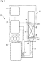
- Fig. 1 illustrates a control system 50 of an internal combustion engine equipped with a catalyst deterioration detecting system 9 according to the present embodiment.
- An example of the control system 50 is a control system of an engine of a vehicle.
- the control system 50 illustrated in Fig. 1 includes an engine 11, and an exhaust pipe 12 that guides exhaust gas from the engine 11 to the exterior.
- a catalyst 8 is provided midway of the exhaust pipe 12.
- the shape of the exhaust pipe 12 is not limited; for example, the exhaust pipe may have, at a position upstream of where the catalyst 8 is provided, an increasing-diameter portion whose diameter increases toward the catalyst 8, as illustrated in Fig. 1 .
- the catalyst 8 is an oxidation catalyst that oxidizes carbon monoxide (CO) and hydrocarbons (HC) in the exhaust gas of the engine 11 and purifies them into carbon dioxide and water, and more preferably, is a three-way catalyst that simultaneously performs reduction of NOx into nitrogen together with the oxidation.
- An example of the catalyst is a powder including, in combination, noble metals, such as Pt, Pd, and Rh, and alumina, ceria, zirconia, and/or composite oxides thereof.
- the powder is usually employed as a catalyst layer supported on a catalyst support.
- the catalyst support is made, for example, of ceramic or a metal material.
- the shape of the catalyst support is not particularly limited; in general, the catalyst support is shaped, for example, into a honeycomb configuration, a plate, pellets, a DPF, or a GPF, and is preferably a honeycomb, a DPF, or a GPF.
- materials for the catalyst support include ceramics, such as alumina (Al 2 O 3 ), mullite (3Al 2 O 3 -2SiO 2 ), cordierite (2MgO-2Al 2 O 3 -5SiO 2 ), aluminum titanate (Al 2 TiO 5 ), and silicon carbide (SiC), and metal materials such as stainless steel.
- the catalyst deterioration detecting system 9 of the present embodiment illustrated in Fig. 1 includes: an upstream-side temperature detection means 5 that detects a temperature on the upstream side of the catalyst 8 in the exhaust passage (the exhaust pipe 12 in the example illustrated in Fig. 1 ); a downstream-side temperature detection means 6 that detects a temperature on the downstream side of the catalyst 8 in the exhaust passage (the exhaust pipe 12 in the example illustrated in Fig. 1 ); and an engine control unit (ECU) 10 that recognizes change points T1 and T1' in temperatures detected by the upstream-side temperature detection means 5 and change points T2 and T2' in temperatures detected by the downstream-side temperature detection means 6, and determines deterioration of the catalyst on the basis of the change points.
- ECU engine control unit
- Temperature sensors can be used for the upstream-side temperature detection means 5 and the downstream-side temperature detection means 6. Concrete examples of temperature sensors include thermocouples and temperature measurement resistors.
- the upstream-side temperature detection means 5 is provided on the upstream side of the catalyst 8 in the exhaust pipe 12
- the downstream-side temperature detection means 6 is provided on the downstream side of the catalyst 8 in the exhaust pipe 12. It is preferable that, in a cross section orthogonal to the length direction of the exhaust pipe 12, the upstream-side temperature detection means 5 and the downstream-side temperature detection means 6 are provided so as to be able to detect the temperature at substantially the central portion in the cross section.
- substantially the central portion in the cross section is in a range within two-thirds, preferably one-third, of the distance from the center of the exhaust pipe to the inner surface of the exhaust pipe in the aforementioned cross section.
- the center of the exhaust pipe in the aforementioned cross section refers to the center of the circle
- the center of the exhaust pipe refers to the center of the largest circle that can be rendered inside the cross section.
- the "cross section of the exhaust pipe 12" refers to the cross section orthogonal to the length direction of the exhaust pipe 12, unless specifically stated otherwise.
- the intake pressure of the engine, the engine rotation speed, the throttle opening angle, and the air-fuel ratio are detected respectively by a Pb sensor 1, an Ne sensor 2, a Th sensor 3, and an O 2 sensor 4, and are controlled by the engine control unit (ECU) 10.
- the Pb sensor 1, the Ne sensor 2, the Th sensor 3, and the O 2 sensor 4 may be included in the catalyst deterioration detecting system 9.
- the catalyst deterioration detecting system 9 of the present embodiment is provided in a device including an internal combustion engine, such as a transportation means, e.g., a vehicle, an airplane or a ship, or a power generator, as a part of the control system 50 of the internal combustion engine illustrated in Fig. 1 .
- the catalyst deterioration detecting system 9 detects catalyst deterioration on the basis of an interval between the times, respectively on the upstream and downstream sides of the catalyst 8, at which the inclination of the detected temperature is inverted during acceleration operation or deceleration operation of the internal combustion engine.
- inverted includes cases where the inclination changes from positive to negative and cases where the inclination changes from negative to positive, and also includes cases where the inclination changes from zero to positive or negative.
- a transportation means such as a vehicle
- the internal combustion engine will undergo acceleration operation (for example, an increase in the rotation speed (rpm) of an engine shaft).
- the internal combustion engine will undergo deceleration operation (for example, a decrease in the rotation speed (rpm) of an engine shaft).
- the catalyst deterioration detecting system 9 of the present embodiment can detect catalyst deterioration on the basis of an interval between the times at which the inclination of the respective temperatures detected respectively by the upstream-side temperature detection means 5 and the downstream-side temperature detection means 6 is inverted during acceleration operation or deceleration operation of the transportation means.
- acceleration operation of a transportation means refers, for example in cases of a vehicle, to an acceleration of 0.52 m/sec 2 or greater, or an acceleration in which the speed difference before and after acceleration is 30 km/h or greater.
- deceleration operation of a transportation means refers, for example in cases of a vehicle, to a deceleration of 0.52 m/sec 2 or greater, or a deceleration in which the speed difference before and after deceleration is 20 km/h or greater.
- Fig. 2 illustrates an example plotting a change in vehicle speed during acceleration operation of a transporting means equipped with the catalyst deterioration detecting system 9 (and the internal combustion engine's control system 50 including the same) of the present embodiment, and a change in temperature detected by the upstream-side temperature detection means 5 and the downstream-side temperature detection means 6.
- the temperature of the exhaust gas increases along with the acceleration operation of the internal combustion engine, and thus, the temperature detected by the upstream-side temperature detection means 5 immediately changes from temperature fall or constant temperature to temperature rise, to give a change point T1 from temperature fall or constant temperature to temperature rise.
- the temperature detected by the downstream-side temperature detection means 6 changes from temperature fall or constant temperature to temperature rise in a delayed manner compared to the upstream-side temperature detection means, to give a change point T2a or T2b.
- This delay not only reflects the distance between the engine 11 and the downstream-side temperature detection means 6, but also reflects the fact that the oxidation reaction caused by the catalyst 8, which occurs as a result of the catalyst 8 coming into contact with the exhaust gas, is an exothermic reaction.
- the greater the degree of catalyst deterioration the further delayed the occurrence of the change from temperature fall or constant temperature to temperature rise at the downstream-side temperature detection means 6 becomes, and that this can be employed to detect deterioration of the catalyst. This is thought to be because, the further the deterioration of the catalyst progresses, the more the oxidation reaction of HC and CO by the catalyst is delayed.
- Fig. 3 illustrates an example plotting a change in vehicle speed during deceleration operation of a transporting means equipped with the catalyst deterioration detecting system 9 (and the internal combustion engine's control system 50 including the same) of the present embodiment, and a change in temperature detected by each of the temperature detection means. As illustrated in Fig.
- the upstream-side temperature detection means 5 detects a change point T1' from temperature rise or constant temperature to temperature fall.
- the downstream-side temperature detection means 6 detects a change point T2'a or T2'b from temperature rise or constant temperature to temperature fall in a delayed manner compared to the upstream-side temperature detection means.
- the greater the degree of deterioration of the catalyst 8 the further delayed the change from temperature rise or constant temperature to temperature fall at the downstream-side temperature detection means 6 becomes, compared to the change from temperature rise or constant temperature to temperature fall at the upstream-side temperature detection means 5.
- deterioration of the catalyst can be detected by employing the difference ⁇ T' between the change points T1' and T2'.
- step 1 determines whether or not an internal combustion engine, or a transportation means etc. equipped therewith, is performing acceleration operation or deceleration operation. This determination is performed, for example, by detecting the rotation speed of the engine shaft with the Ne sensor 2, and, on the basis of this information, making the determination by the ECU 10.
- the ECU 10 is constituted by arithmetic processing means including a CPU, a memory, etc. If Yes, the flow advances to step 2, in which the temperature of the catalyst 8 is measured and it is determined by the ECU 10 whether or not the temperature of the catalyst 8 is within a predetermined range.
- the temperature range of the catalyst 8 to be set as the predetermined range in step 2 is preferably from 300°C to 600°C, more preferably from 400°C to 500°C.
- the temperature of the catalyst 8 may be measured with the downstream-side temperature detection means 6, or may be measured with a separate temperature detection means inserted into the catalyst 8.
- the recognition unit and the determination unit of the invention may be a single control device.
- Examples of instances in which an internal combustion engine, as well as transportation means etc. equipped therewith, performs acceleration operation in step 1 in a state where the catalyst 8 has been heated to a given temperature as described above include the following: when the internal combustion engine is an engine of a vehicle, an instance in which the vehicle speed is increased from a state where the vehicle is traveling at a constant speed; and an instance in which the vehicle speed is increased from an idling state or a state where the vehicle speed is decreasing. Examples of instances in which an internal combustion engine, as well as transportation means etc.
- step 1 performs deceleration in step 1 in a state where the catalyst 8 has been heated to a given temperature
- the internal combustion engine is an engine of a vehicle, an instance in which the vehicle speed is decreased from a state where the vehicle is traveling at a constant speed or a state where the vehicle speed is increasing.
- the conditions for recognizing whether or not a change has occurred from temperature fall or constant temperature to temperature rise can be set as appropriate to conditions with which deterioration detection can be performed efficiently.
- recognition of a change point from temperature fall or constant temperature to temperature rise for example, in cases where the measurement is performed at intervals of 0.1 seconds, a point at which an increase in measured temperature of at least 0.1°C compared to the immediately-previous temperature measurement history of the upstream-side temperature detection means 5 has occurred three consecutive times is recognized as the change point T1, and likewise, a point at which an increase in measured temperature of at least 0.1°C compared to the immediately-previous temperature measurement history of the downstream-side temperature detection means 6 has occurred three consecutive times is recognized as the change point T2.
- Recognition of a change point from temperature rise or constant temperature to temperature fall is performed similarly; for example, in cases where the measurement is performed at intervals of 0.1 seconds, a point at which a decrease in measured temperature of at least 0.1°C compared to the immediately-previous temperature measurement history of the upstream-side temperature detection means 5 has occurred three consecutive times is recognized as the change point T1', and likewise, a point at which a decrease in measured temperature of at least 0.1°C compared to the immediately-previous temperature measurement history of the downstream-side temperature detection means 6 has occurred three consecutive times is recognized as the change point T2'.
- step 4 the ECU 10 determines whether or not ⁇ T or ⁇ T' calculated in step 3 is equal to or greater than a predetermined value. If Yes, in step 5, the ECU 10 outputs a signal for displaying a warning on a monitor 7. Note that, in cases where steps 1, 2, and 4 are No, the flow is ended, and the same flow is resumed after the lapse of a predetermined period of time.
- the predetermined value serving as the determination criterion may be set discretionarily to a value suitable for the concrete configuration of the system.
- the catalyst deterioration detecting system and catalyst deterioration detecting method of the present embodiment are described in further detail.
- Inventors have studied methods for improving deterioration detection sensitivity at the time of detecting catalyst deterioration by employing the aforementioned ⁇ T, and arrived at making respective time constants of the upstream-side temperature detection means and the downstream-side temperature detection means different from one another.
- the time constant is an index of the response speed of the temperature detection means with respect to the temperature rise or temperature fall of the surrounding environment.
- the time constants of the upstream-side temperature detection means 5 and the downstream-side temperature detection means 6 differ depending on whether the surrounding environment is undergoing temperature rise or temperature fall, and can be measured as follows.
- each temperature detection means which is in a state detecting 25°C, is set to a central portion, in the length direction, of the exhaust pipe so as to detect the temperature at the central portion in the cross section of the exhaust pipe.
- a chart is obtained by plotting the temperature change of the temperature detection means at intervals of 0.1 seconds up to 405°C. The chart is subjected to linear regression, and the inclination (unit: °C/sec) of the obtained linear function/straight line is found as the time constant during temperature rise.
- each temperature detection means is set at a central portion, in the length direction, of a 245-mm-long stainless steel exhaust pipe having a cross-sectional area of 21.06 cm 2 and through which an exhaust gas giving a detection temperature of 450°C flows at a flow rate of 5 L/sec. From this state, the temperature detection means is set in the atmosphere having a temperature of 25°C and an air velocity of 16.7 m/sec, to obtain a chart plotting the temperature change of the temperature detection means at intervals of 0.1 seconds down to 30°C. The chart is subjected to linear regression, and the inclination (unit: °C/sec) of the obtained linear function/straight line is found as the time constant during temperature fall.
- the exhaust gas used for measuring the time constants in the Examples is used as the exhaust gas for measuring the aforementioned time constants.
- time constant t ⁇ -r the time constant of the upstream-side temperature detection means 5 during temperature rise
- time constant t ⁇ -r the time constant of the downstream-side temperature detection means 6 during temperature rise
- setting the ratio to equal to or below a given value facilitates ensuring the ease of deriving the change points for both the upstream-side temperature detection means 5 and the downstream-side temperature detection means 6.
- the ratio t ⁇ -r /t ⁇ -r is preferably from 0.15 to 0.85, more preferably from 0.25 to 0.80, even more preferably from 0.25 to 0.50.
- the time constant t ⁇ -r of the upstream-side temperature detection means 5 during temperature rise is preferably 20.0°C/sec or greater, more preferably 27.0°C/sec or greater.
- the time constant t ⁇ -r of the downstream-side temperature detection means 6 during temperature rise is preferably from 5.0°C/sec to 11.5°C/sec, more preferably from 7.0°C/sec to 7.5°C/sec.
- time constant t ⁇ -1 between the time constant of the upstream-side temperature detection means 5 during temperature fall (referred to hereinafter also as “time constant t ⁇ -1 ") and the time constant of the downstream-side temperature detection means 6 during temperature fall (referred to hereinafter also as “time constant t ⁇ -1 ")
- time constant t ⁇ -1 the time constant of the downstream-side temperature detection means 6 during temperature fall
- setting the ratio to equal to or below a given value facilitates ensuring the ease of deriving the change points for both the upstream-side temperature detection means 5 and the downstream-side temperature detection means 6.
- the ratio t ⁇ -1 /t ⁇ -1 is preferably from 0.05 to 0.70, more preferably from 0.25 to 0.65, even more preferably from 0.25 to 0.45.
- the time constant t ⁇ -1 of the upstream-side temperature detection means 5 during temperature fall is preferably -16.0°C/sec or less, more preferably -26.0°C/sec or less.
- the time constant t ⁇ -1 of the downstream-side temperature detection means 6 during temperature fall is preferably from -9.0°C/sec to -2.0°C/sec, more preferably from -7.7°C/sec to -7.2°C/sec.
- the respective absolute values of the time constants during temperature rise and temperature fall are preferably both within a range from 2.0 to 25.0, more preferably within a range from 5.0 to 20.0, and particularly, it is preferably within a range from 5.5 to 8.5 from the viewpoint of maximizing the frequency of detecting ⁇ T.
- Methods for making the time constants different between the upstream-side temperature detection means 5 and the downstream-side temperature detection means 6 include, for example: a method of using sheathed thermocouples for the upstream-side temperature detection means 5 and the downstream-side temperature detection means 6 and using different materials for the sheathed thermocouples; a method of making the sheath diameters different; and a method of attaching, to the outer circumference of the sheathed thermocouple, a barrier material having a thermal conductivity different from the thermal conductivity of the sheathed thermocouple.
- a known type of sheathed thermocouple is made by joining two different types of bare wires at their tip ends, and measures the temperature by employing the Seebeck effect, in which a thermoelectromotive force occurs in the closed circuit, and thereby a current flows through the circuit, when a temperature difference occurs between the two junctions.
- the junction on the temperature-measuring side is called the measuring junction.
- the sheathed thermocouple is made by housing the thermocouple bare wires in a sheath, which is a protection tube, and integrating the wires and the sheath by filling and sealing the sheath with an insulating material.
- the sheathed thermocouple may be a JIS-compliant thermocouple or a thermocouple not compliant with JIS, but is preferably a thermocouple capable of supporting exhaust temperatures of around 200°C to 800°C from an internal combustion engine, and examples include Chromel-Alumel (K) thermocouples, platinum-platinum/rhodium (R) thermocouples, and Nicrosil-Nisil (N) thermocouples.
- K Chromel-Alumel
- R platinum-platinum/rhodium
- N Nicrosil-Nisil
- a preferred material for the sheath is metal, with examples including stainless steel (e.g., SUS 316, SUS 310S, SUS 347) and chromium-nickel alloys (NCF 600).
- An example of an inorganic insulating material is magnesium oxide (MgO).
- the length of the sheathed thermocouple is not limited, but is generally from 0.15 m to 0.5 m, for example.
- the types, materials, etc. may be the same, or may be different from one another.
- the sheath diameter refers to the outer diameter (the outer-side diameter) at the measuring junction.
- the sheath diameter refers to the equivalent circle diameter of an area of a portion (including the sheath's wall thickness) that is present inside the sheath's outer shape at the aforementioned cross section.
- the wall thickness of the sheath is not particularly limited, and is set in accordance with the sheath diameter; in cases of two types of sheathed thermocouples having different sheath diameters, the thermocouple having a greater sheath diameter often has a greater wall thickness.
- the sheath diameter of the sheathed thermocouple used for the downstream-side temperature detection means 6 greater than the sheath diameter of the sheathed thermocouple used for the upstream-side temperature detection means 5 from the viewpoint of effectively improving the sensitivity for detecting catalyst deterioration.
- ⁇ 1 is defined as the sheath diameter of the sheathed thermocouple used as the upstream-side temperature detection means 5 and ⁇ 2 is defined as the sheath diameter of the sheathed thermocouple used as the downstream-side temperature detection means 6, it is preferable that the ratio ⁇ 2/ ⁇ 1 between ⁇ 1 and ⁇ 2 is greater than 1 and preferably 4.5 or less, and more preferably from 2.0 to 4.0 from the viewpoint of particularly improving detection sensitivity.
- the sheath diameter of the sheathed thermocouple is not particularly limited so long as it provides the aforementioned preferable time constant.
- the sheath diameter ⁇ 1 is preferably 1.6 mm or greater from the viewpoint of durability such as corrosion resistance, and preferably 2.3 mm or less from the viewpoint of easily improving deterioration detection sensitivity because ⁇ T can be increased easily.
- the sheath diameter ⁇ 2 is preferably 2.3 mm or greater from the viewpoint of durability such as corrosion resistance and from the viewpoint of easily improving deterioration detection sensitivity because ⁇ T can be increased easily
- the sheath diameter ⁇ 2 is preferably 4.8 mm or less from the viewpoint of easily improving deterioration detection sensitivity because T2 is easy to detect.
- the ratio L2/L1 between a distance L1 (see Fig. 1 ) from an inlet-side end portion 8a of the catalyst 8 to a temperature detection position of the upstream-side temperature detection means 5 and a distance L2 (see Fig.
- L2/L1 is preferably from 0.18 to 5.00, more preferably from 0.5 to 3.0.
- the "inlet-side” refers to the side of the inlet of the exhaust in the exhaust passage 12, and the “outlet-side” refers to the side of the outlet of the exhaust in the exhaust passage 12.
- L1 is preferably from 20 to 400 mm, more preferably from 20 to 110 mm, from the viewpoint of detecting T1 (or T1') accurately from exhaust heat and improving catalyst deterioration detection sensitivity.
- L2 is preferably from 20 to 100 mm, more preferably from 20 to 70 mm, from the viewpoint of improving catalyst deterioration detection sensitivity and detecting T2 (or T2') accurately.
- Examples of usable internal combustion engines include gasoline engines, diesel engines, hybrid engines, and engines using fuels such as natural gas, ethanol, and dimethyl ether.
- gasoline engines are preferred, because the exhaust gas has a large heat quantity and thus determination of deterioration detection based on ⁇ T (or ⁇ T') is easy.
- the catalyst deterioration detecting system and catalyst deterioration detecting method of the present embodiment described above are suitably applicable for detecting deterioration of an exhaust-gas purifying catalyst for purifying exhaust gas emitted from an engine of, for example, an automobile or a motorcycle (saddle-type vehicle) by making use of the low cost, versatility, and deterioration detection sensitivity of the system/method.
- Sheathed thermocouples (all products of Nikkato Corporation) respectively having sheath diameters as described in Table 1 below were used. Each sheathed thermocouple which was at 25°C was inserted to a center, in the length direction, of an exhaust pipe (length: 245 mm) having a cross-sectional area of 21.06 cm 2 and made of stainless steel (SUS 304) and through which a 450°C exhaust gas flows at a flow rate of 5 L/sec, so as to detect the temperature at the central portion, in the cross section, of the exhaust pipe, and the temperature detected by the thermocouple was plotted up to 405°C at intervals of 0.1 seconds.
- SUS 304 stainless steel
- each sheathed thermocouple which was at 450°C was set in an atmospheric environment having a temperature of 25°C and an air velocity of 16.7 m/sec, and the temperature detected by the thermocouple was plotted down to 30°C at intervals of 0.1 seconds.
- the time-to-temperature chart obtained for each Reference Example was subjected to linear regression with calculation software (Excel ver. 2010).
- the inclination of the linear function was found as the time constant and is shown in Table 1.
- the exhaust gas used above had the following composition in terms of volume: 100 ppm CO; 15.0% CO 2 ; 50 ppmTHC; 0.01% or less O 2 ; 50 ppmNO X ; and N 2 as the balance.
- Test catalysts 8 were each prepared by subjecting a three-way catalyst (product of Mitsui Mining & Smelting Co., Ltd.) to a deterioration treatment by setting the catalyst in an engine bench either for 30 hours, 65 hours or 100 hours at a catalyst temperature of 900°C or higher.
- a three-way catalyst product of Mitsui Mining & Smelting Co., Ltd.
- Each of these deteriorated catalysts which have undergone different lengths of deterioration treatment time (also referred to as "deterioration duration time"), was attached to a catalyst-setting position in the exhaust pipe downstream of a gasoline engine of a vehicle, and in this state, the engine was subjected test drive.
- the emission amount (g/km) of each of CO, HC, and NOx emitted from the exhaust outlet of the exhaust pipe was measured.
- AIA-720 (product of Horiba, Ltd.) was used for CO measurement
- FIA-720 (product of Horiba, Ltd.) was used for HC measurement
- CLA-720A (product of Horiba, Ltd.) was used for NOx measurement.
- the respective emission amounts of CO, HC, and NOx with respect to the catalysts' respective deterioration duration time are shown in Fig. 5 .
- An engine control system 50 including the catalyst deterioration detecting system 9 of the present embodiment, was installed for catalyst deterioration detection to a saddle-type vehicle equipped with a gasoline engine.
- the deteriorated catalysts (after measuring the amount of exhaust gas in Reference Example 7) each having different lengths of deterioration duration time were each installed as the catalyst 8 to the system 50.
- sheathed thermocouples having a sheath diameter of 1.6 mm used in Reference Example 1 were used.
- the upstream-side temperature detection means 5 was set such that its temperature detection position was at a position in the exhaust pipe so as to be separated by 20 mm toward the upstream side from the inlet-side end portion 8a of the catalyst 8.
- the downstream-side temperature detection means 6 was set such that its temperature detection position was at a position so as to be separated by 60 mm toward the downstream side from the outlet-side end portion 8b of the catalyst 8.
- thermocouples respectively having sheath diameters of 2.3 mm, 3.2 mm, 4.8 mm, 6.4 mm, or 8.0 mm were used for the downstream-side temperature detection means 6.
- the correspondence between the Examples and the sheath diameters of the downstream-side temperature detection means 6 is as illustrated in Figs. 6(a) and 6(b) .
- the catalyst deterioration detecting system of each Example was mounted on a saddle-type vehicle, and the saddle-type vehicle was driven at 60 km/h for 15 minutes, then decelerated to 0 km/h over 20 seconds, and then stopped in an idling state for 1 minute, and then either accelerated from 0 km/h to 32 km/h over 12 seconds or from 0 km/h to 50 km/h over 26 seconds.
- Fig. 6 shows charts plotting the differences ⁇ T between change points with respect to the deterioration duration time of the respective deteriorated catalysts.
- ⁇ T increases with an increase in deterioration duration time. This shows that the system of the invention is capable of detecting ⁇ T corresponding to a progress in deterioration, and is useful in detecting catalyst deterioration. Further, the description of Fig.
- the same acceleration test as in Evaluation 1-1 was repeated twelve times (that is, acceleration from 0 km/h to 32 km/h was performed six times, and acceleration from 0 km/h to 50 km/h was performed six times).
- the first acceleration test corresponding to initial warming-up that is, the first acceleration from 0 km/h to 32 km/h and the first acceleration from 0 km/h to 50 km/h is in the start-up stage and thus detection performance is less likely to be stable.
- Fig. 7 shows the obtained chart. More specifically, determination as to whether ⁇ T corresponding to the degree of catalyst deterioration was verified or not was performed by: respectively recording, from upstream temperature data and downstream temperature data immediately after entering acceleration operation, the number of seconds after the change point at which the temperature changed to temperature rise (i.e., the cumulative time during the test); finding ⁇ T as the difference in time; and verifying whether the time difference ⁇ T became longer in accordance with deterioration duration time.
- Fig. 7 shows that, particularly when the sheath diameter is from 3.2 mm to 6.4 mm, the frequency of detecting ⁇ T corresponding to the degree of catalyst deterioration becomes highest.
- Example 1 yielded six times
- Example 2 yielded six times
- Example 3 yielded six times
- Example 4 yielded ten times
- Example 5 yielded six times
- Example 6 yielded five times. This shows that the system of the present invention can sufficiently detect ⁇ T even when the first test, wherein detection performance is less likely to be stable, was included.
- the detection of ⁇ T during deceleration testing was evaluated, opposite from the Evaluations 1-1 to 1-3. More specifically, using each of the deteriorated catalysts for which the deterioration duration time was respectively 30, 65, or 100 hours, deceleration tests were repeated five times each (that is, deceleration from 70 km/h to 50 km/h was performed five times). The first and second deceleration tests correspond to initial warming-up; so, for a total of three tests excluding the above two tests, evaluation was made as to whether or not ⁇ T corresponding to the degree of catalyst deterioration was verified. The result was that it was possible to detect ⁇ T all three times.
- the present invention provides a highly versatile, inexpensive catalyst deterioration detecting system and catalyst deterioration detecting method capable of easily detecting deterioration of a catalyst without using an O 2 sensor.
Landscapes
- Engineering & Computer Science (AREA)
- Chemical & Material Sciences (AREA)
- Combustion & Propulsion (AREA)
- Mechanical Engineering (AREA)
- General Engineering & Computer Science (AREA)
- Chemical Kinetics & Catalysis (AREA)
- Health & Medical Sciences (AREA)
- General Physics & Mathematics (AREA)
- Physics & Mathematics (AREA)
- Toxicology (AREA)
- Materials Engineering (AREA)
- Analytical Chemistry (AREA)
- Environmental & Geological Engineering (AREA)
- Biomedical Technology (AREA)
- General Chemical & Material Sciences (AREA)
- Oil, Petroleum & Natural Gas (AREA)
- Biochemistry (AREA)
- Life Sciences & Earth Sciences (AREA)
- Pathology (AREA)
- Immunology (AREA)
- General Health & Medical Sciences (AREA)
- Exhaust Gas After Treatment (AREA)
Abstract
Description
- The present invention relates to a catalyst deterioration detecting system and a catalyst deterioration detecting method for an internal combustion engine.
- Exhaust gas emitted from an internal combustion engine, such as a gasoline engine or a diesel engine, of an automobile, a motorcycle (also referred to as a saddle-type vehicle), etc., contains hazardous components such as NOx, HC, and CO. Three-way catalysts have conventionally been used to remove these hazardous components and render the exhaust gas harmless. Examples of three-way catalysts that have been used include mixtures including discretionary amounts of noble metals, such as Pt, Pd, and Rh, and alumina, ceria, zirconia, and/or composite oxides thereof.
- As a part of exhaust gas regulation, the OBD-II regulation was introduced in the United States from around 1990, the regulation mandating the installation, onto a vehicle, of a system that: detects abnormalities, such as deterioration of an exhaust gas purification catalyst (hereinafter also referred to simply as "catalyst"); and, upon detection of such abnormalities by an on-board diagnostic (OBD) device, notifies the driver of the abnormality by lighting up a warning lamp on an instrument panel, and stores the failure code(s) which can be read out with a standardized scanning tool. Similar regulations have been introduced in Europe and Japan. Thus, there is a demand for an inexpensive, versatile system capable of detecting deterioration of a catalyst.
- As disclosed in
Patent Literatures Patent Literatures 3 and 4, on the other hand, disclose techniques that do not employ O2 sensors but instead include temperature detection means on both the upstream and downstream sides of a catalyst in an exhaust passage of an internal combustion engine, and detect deterioration on the basis of a difference between the temperatures detected by both means. -
- Patent Literature 1:
JP H8-303280 A - Patent Literature 2:
JP 2004-176615 A - Patent Literature 3:
JP 2014-62510 A - Patent Literature 4:
US 2002/197721 A1 - In general, O2 sensors use platinum-coated zirconia electrolytes and are thus expensive. Thus, there is a demand for inexpensive catalyst deterioration detecting systems that do not use O2 sensors, in contrast to the systems disclosed in
Patent Literatures Patent Literatures 3 and 4 disclose systems for detecting catalyst deterioration without using an O2 sensor.Patent Literatures 3 and 4, however, merely describe the employment of a temperature difference between the upstream and downstream sides of a catalyst, and are not necessarily suitable for actual driving environments in which the accelerator and the brake are frequently used. - An objective of the invention is to provide a catalyst deterioration detecting system and a catalyst deterioration detecting method capable of overcoming the various drawbacks of the aforementioned conventional art.
- The present invention provides a catalyst deterioration detecting system for detecting deterioration of a catalyst provided in an exhaust passage of an internal combustion engine, the system including:
- an upstream-side temperature detection means that detects a temperature of an exhaust on an upstream side of the catalyst;
- a downstream-side temperature detection means that detects a temperature of the exhaust on a downstream side of the catalyst; and either
- (A) a recognition unit that, during acceleration operation, recognizes a change point (T1) detected by the upstream-side temperature detection means at which the temperature changes from temperature fall or constant temperature to temperature rise and a change point (T2) detected by the downstream-side temperature detection means at which the temperature changes from temperature fall or constant temperature to temperature rise, and a determination unit that determines that the catalyst has deteriorated when a difference between the change points (ΔT=T2-T1) becomes equal to or longer than a predetermined time, or
- (B) a recognition unit that, during deceleration operation, recognizes a change point (Tl') detected by the upstream-side temperature detection means at which the temperature changes from temperature rise or constant temperature to temperature fall and a change point (T2') detected by the downstream-side temperature detection means at which the temperature changes from temperature rise or constant temperature to temperature fall, and a determination unit that determines that the catalyst has deteriorated when a difference between the change points (ΔT'=T2'-T1') becomes equal to or longer than a predetermined time.
- The present invention also provides a catalyst deterioration detecting method for detecting deterioration of a catalyst provided in an exhaust passage of an internal combustion engine, the method including:
employing - an upstream-side temperature detection means that detects a temperature of an exhaust on an upstream side of the catalyst, and
- a downstream-side temperature detection means that detects a
- (a) recognizing, during acceleration operation, a change point (T1) detected by the upstream-side temperature detection means at which the temperature changes from temperature fall or constant temperature to temperature rise and a change point (T2) detected by the downstream-side temperature detection means at which the temperature changes from temperature fall or constant temperature to temperature rise, and determining that the catalyst has deteriorated when a difference between the change points (ΔT=T2-T1) becomes equal to or longer than a predetermined time, or
- (b) recognizing, during deceleration operation, a change point (Tl') detected by the upstream-side temperature detection means at which the temperature changes from temperature rise or constant temperature to temperature fall and a change point (T2') detected by the downstream-side temperature detection means at which the temperature changes from temperature rise or constant temperature to temperature fall, and determining that the catalyst has deteriorated when a difference between the change points (ΔT'=T2'-T1') becomes equal to or longer than a predetermined time.
-
- [
Fig. 1] Fig. 1 is a schematic diagram illustrating an example of an overall configuration of a control system of an internal combustion engine. - [
Fig. 2] Fig. 2 is an example of a chart plotting a change in vehicle speed during acceleration operation of a vehicle equipped with a catalyst deterioration detecting system of the invention, and a change in temperature detected by each temperature detection means. - [
Fig. 3] Fig. 3 is an example of a chart plotting a change in vehicle speed during deceleration operation of a vehicle equipped with a catalyst deterioration detecting system of the invention, and a change in temperature detected by each temperature detection means. - [
Fig. 4] Fig. 4 is a flowchart illustrating an example of a process carried out by a catalyst deterioration detecting system and a catalyst deterioration detecting method of the invention. - [
Fig. 5] Fig. 5(a) illustrates the CO emission amounts of deteriorated catalysts used for evaluation in the Examples,Fig. 5(b) illustrates the HC emission amounts of the deteriorated catalysts, andFig. 5(c) illustrates the NOx emission amounts of the deteriorated catalysts. - [
Fig. 6] Figs. 6(a) and 6(b) are charts illustrating differences ΔT between change points when the deteriorated catalysts were used in the Examples.Fig. 6(a) illustrates a chart for acceleration from 0 km/h to 32 km/h, andFig. 6(b) illustrates a chart for acceleration from 0 km/h to 50 km/h. - [
Fig. 7] Fig. 7 is a chart illustrating the number of times catalyst deterioration was detected in the Examples. - The present invention is described below according to preferred embodiments thereof.
-
Fig. 1 illustrates acontrol system 50 of an internal combustion engine equipped with a catalystdeterioration detecting system 9 according to the present embodiment. An example of thecontrol system 50 is a control system of an engine of a vehicle. Thecontrol system 50 illustrated inFig. 1 includes anengine 11, and anexhaust pipe 12 that guides exhaust gas from theengine 11 to the exterior. Acatalyst 8 is provided midway of theexhaust pipe 12. The shape of theexhaust pipe 12 is not limited; for example, the exhaust pipe may have, at a position upstream of where thecatalyst 8 is provided, an increasing-diameter portion whose diameter increases toward thecatalyst 8, as illustrated inFig. 1 . Thecatalyst 8 is an oxidation catalyst that oxidizes carbon monoxide (CO) and hydrocarbons (HC) in the exhaust gas of theengine 11 and purifies them into carbon dioxide and water, and more preferably, is a three-way catalyst that simultaneously performs reduction of NOx into nitrogen together with the oxidation. An example of the catalyst is a powder including, in combination, noble metals, such as Pt, Pd, and Rh, and alumina, ceria, zirconia, and/or composite oxides thereof. The powder is usually employed as a catalyst layer supported on a catalyst support. The catalyst support is made, for example, of ceramic or a metal material. The shape of the catalyst support is not particularly limited; in general, the catalyst support is shaped, for example, into a honeycomb configuration, a plate, pellets, a DPF, or a GPF, and is preferably a honeycomb, a DPF, or a GPF. Examples of materials for the catalyst support include ceramics, such as alumina (Al2O3), mullite (3Al2O3-2SiO2), cordierite (2MgO-2Al2O3-5SiO2), aluminum titanate (Al2TiO5), and silicon carbide (SiC), and metal materials such as stainless steel. - The catalyst
deterioration detecting system 9 of the present embodiment illustrated inFig. 1 includes: an upstream-side temperature detection means 5 that detects a temperature on the upstream side of thecatalyst 8 in the exhaust passage (theexhaust pipe 12 in the example illustrated inFig. 1 ); a downstream-side temperature detection means 6 that detects a temperature on the downstream side of thecatalyst 8 in the exhaust passage (theexhaust pipe 12 in the example illustrated inFig. 1 ); and an engine control unit (ECU) 10 that recognizes change points T1 and T1' in temperatures detected by the upstream-side temperature detection means 5 and change points T2 and T2' in temperatures detected by the downstream-side temperature detection means 6, and determines deterioration of the catalyst on the basis of the change points. Temperature sensors can be used for the upstream-side temperature detection means 5 and the downstream-side temperature detection means 6. Concrete examples of temperature sensors include thermocouples and temperature measurement resistors. InFig. 1 , the upstream-side temperature detection means 5 is provided on the upstream side of thecatalyst 8 in theexhaust pipe 12, and the downstream-side temperature detection means 6 is provided on the downstream side of thecatalyst 8 in theexhaust pipe 12. It is preferable that, in a cross section orthogonal to the length direction of theexhaust pipe 12, the upstream-side temperature detection means 5 and the downstream-side temperature detection means 6 are provided so as to be able to detect the temperature at substantially the central portion in the cross section. Herein, it is sufficient if "substantially the central portion in the cross section" is in a range within two-thirds, preferably one-third, of the distance from the center of the exhaust pipe to the inner surface of the exhaust pipe in the aforementioned cross section. In cases where the cross section of the exhaust pipe is circular, the center of the exhaust pipe in the aforementioned cross section refers to the center of the circle, and in cases where the exhaust pipe is not circular, the center of the exhaust pipe refers to the center of the largest circle that can be rendered inside the cross section. Note that, hereinbelow, the "cross section of theexhaust pipe 12" refers to the cross section orthogonal to the length direction of theexhaust pipe 12, unless specifically stated otherwise. - In the
engine control system 50 ofFig. 1 , the intake pressure of the engine, the engine rotation speed, the throttle opening angle, and the air-fuel ratio are detected respectively by aPb sensor 1, anNe sensor 2, a Th sensor 3, and an O2 sensor 4, and are controlled by the engine control unit (ECU) 10. As illustrated inFig. 1 , thePb sensor 1, theNe sensor 2, the Th sensor 3, and the O2 sensor 4 may be included in the catalystdeterioration detecting system 9. - The catalyst
deterioration detecting system 9 of the present embodiment is provided in a device including an internal combustion engine, such as a transportation means, e.g., a vehicle, an airplane or a ship, or a power generator, as a part of thecontrol system 50 of the internal combustion engine illustrated inFig. 1 . The catalystdeterioration detecting system 9 detects catalyst deterioration on the basis of an interval between the times, respectively on the upstream and downstream sides of thecatalyst 8, at which the inclination of the detected temperature is inverted during acceleration operation or deceleration operation of the internal combustion engine. It should be noted that, herein, "inverted" includes cases where the inclination changes from positive to negative and cases where the inclination changes from negative to positive, and also includes cases where the inclination changes from zero to positive or negative. During acceleration operation of a transportation means such as a vehicle (for example, an increase in the movement speed (km/h) of the transportation means), the internal combustion engine will undergo acceleration operation (for example, an increase in the rotation speed (rpm) of an engine shaft). Similarly, during deceleration operation of a vehicle (for example, a decrease in the movement speed (km/h) of the transportation means), the internal combustion engine will undergo deceleration operation (for example, a decrease in the rotation speed (rpm) of an engine shaft). Thus, when installed on a transportation means such as a vehicle, the catalystdeterioration detecting system 9 of the present embodiment can detect catalyst deterioration on the basis of an interval between the times at which the inclination of the respective temperatures detected respectively by the upstream-side temperature detection means 5 and the downstream-side temperature detection means 6 is inverted during acceleration operation or deceleration operation of the transportation means. Preferably, "acceleration operation of a transportation means" refers, for example in cases of a vehicle, to an acceleration of 0.52 m/sec2 or greater, or an acceleration in which the speed difference before and after acceleration is 30 km/h or greater. Preferably, "deceleration operation of a transportation means" refers, for example in cases of a vehicle, to a deceleration of 0.52 m/sec2 or greater, or a deceleration in which the speed difference before and after deceleration is 20 km/h or greater. -
Fig. 2 illustrates an example plotting a change in vehicle speed during acceleration operation of a transporting means equipped with the catalyst deterioration detecting system 9 (and the internal combustion engine'scontrol system 50 including the same) of the present embodiment, and a change in temperature detected by the upstream-side temperature detection means 5 and the downstream-side temperature detection means 6. As illustrated inFig. 2 , during acceleration operation of the transportation means, the temperature of the exhaust gas increases along with the acceleration operation of the internal combustion engine, and thus, the temperature detected by the upstream-side temperature detection means 5 immediately changes from temperature fall or constant temperature to temperature rise, to give a change point T1 from temperature fall or constant temperature to temperature rise. On the other hand, the temperature detected by the downstream-side temperature detection means 6 changes from temperature fall or constant temperature to temperature rise in a delayed manner compared to the upstream-side temperature detection means, to give a change point T2a or T2b. This delay not only reflects the distance between theengine 11 and the downstream-side temperature detection means 6, but also reflects the fact that the oxidation reaction caused by thecatalyst 8, which occurs as a result of thecatalyst 8 coming into contact with the exhaust gas, is an exothermic reaction. Inventors have found that the greater the degree of catalyst deterioration, the further delayed the occurrence of the change from temperature fall or constant temperature to temperature rise at the downstream-side temperature detection means 6 becomes, and that this can be employed to detect deterioration of the catalyst. This is thought to be because, the further the deterioration of the catalyst progresses, the more the oxidation reaction of HC and CO by the catalyst is delayed. - Similarly, also during deceleration operation of the transportation means, deceleration operation of the internal combustion engine occurs, and thus, the temperature falls from temperature rise or constant temperature at the upstream-side temperature detection means 5 and the downstream-side temperature detection means 6.
Fig. 3 illustrates an example plotting a change in vehicle speed during deceleration operation of a transporting means equipped with the catalyst deterioration detecting system 9 (and the internal combustion engine'scontrol system 50 including the same) of the present embodiment, and a change in temperature detected by each of the temperature detection means. As illustrated inFig. 3 , during deceleration operation of the transportation means, the temperature of the exhaust gas decreases along with the deceleration operation of the internal combustion engine, and thus, the upstream-side temperature detection means 5 detects a change point T1' from temperature rise or constant temperature to temperature fall. On the other hand, the downstream-side temperature detection means 6 detects a change point T2'a or T2'b from temperature rise or constant temperature to temperature fall in a delayed manner compared to the upstream-side temperature detection means. Here, the greater the degree of deterioration of thecatalyst 8, the further delayed the change from temperature rise or constant temperature to temperature fall at the downstream-side temperature detection means 6 becomes, compared to the change from temperature rise or constant temperature to temperature fall at the upstream-side temperature detection means 5. Thus, similar to the time of acceleration operation, deterioration of the catalyst can be detected by employing the difference ΔT' between the change points T1' and T2'. - An example of detecting deterioration according to the present embodiment is described according to the flowchart of
Fig. 4 . - As illustrated in
Fig. 4 ,step 1 determines whether or not an internal combustion engine, or a transportation means etc. equipped therewith, is performing acceleration operation or deceleration operation. This determination is performed, for example, by detecting the rotation speed of the engine shaft with theNe sensor 2, and, on the basis of this information, making the determination by theECU 10. TheECU 10 is constituted by arithmetic processing means including a CPU, a memory, etc. If Yes, the flow advances to step 2, in which the temperature of thecatalyst 8 is measured and it is determined by theECU 10 whether or not the temperature of thecatalyst 8 is within a predetermined range. When the temperature of thecatalyst 8 is equal to or above a given value, it is considered that the oxidation reaction upon contact with the exhaust gas has occurred sufficiently, which can facilitate the determination of ΔT. The temperature range of thecatalyst 8 to be set as the predetermined range instep 2 is preferably from 300°C to 600°C, more preferably from 400°C to 500°C. The temperature of thecatalyst 8 may be measured with the downstream-side temperature detection means 6, or may be measured with a separate temperature detection means inserted into thecatalyst 8. As described above, the recognition unit and the determination unit of the invention may be a single control device. - Examples of instances in which an internal combustion engine, as well as transportation means etc. equipped therewith, performs acceleration operation in
step 1 in a state where thecatalyst 8 has been heated to a given temperature as described above include the following: when the internal combustion engine is an engine of a vehicle, an instance in which the vehicle speed is increased from a state where the vehicle is traveling at a constant speed; and an instance in which the vehicle speed is increased from an idling state or a state where the vehicle speed is decreasing. Examples of instances in which an internal combustion engine, as well as transportation means etc. equipped therewith, performs deceleration instep 1 in a state where thecatalyst 8 has been heated to a given temperature include the following: when the internal combustion engine is an engine of a vehicle, an instance in which the vehicle speed is decreased from a state where the vehicle is traveling at a constant speed or a state where the vehicle speed is increasing. - If it is determined Yes in
step 2, the flow advances to step 3. If it was determined instep 1 that acceleration operation is being performed, then theECU 10 recognizes the change point T1 in temperature detected by the upstream-side temperature detection means 5 and the change point T2 in temperature detected by the downstream-side temperature detection means 6, and calculates ΔT (=T2-T1). On the other hand, if it was determined instep 2 that deceleration operation is being performed, then the ECU recognizes the change point T1' in temperature detected by the upstream-side temperature detection means 5 and the change point T2' in temperature detected by the downstream-side temperature detection means 6, and calculates ΔT'(=T2'-T1'). - The conditions for recognizing whether or not a change has occurred from temperature fall or constant temperature to temperature rise can be set as appropriate to conditions with which deterioration detection can be performed efficiently. As regards recognition of a change point from temperature fall or constant temperature to temperature rise, for example, in cases where the measurement is performed at intervals of 0.1 seconds, a point at which an increase in measured temperature of at least 0.1°C compared to the immediately-previous temperature measurement history of the upstream-side temperature detection means 5 has occurred three consecutive times is recognized as the change point T1, and likewise, a point at which an increase in measured temperature of at least 0.1°C compared to the immediately-previous temperature measurement history of the downstream-side temperature detection means 6 has occurred three consecutive times is recognized as the change point T2. Recognition of a change point from temperature rise or constant temperature to temperature fall is performed similarly; for example, in cases where the measurement is performed at intervals of 0.1 seconds, a point at which a decrease in measured temperature of at least 0.1°C compared to the immediately-previous temperature measurement history of the upstream-side temperature detection means 5 has occurred three consecutive times is recognized as the change point T1', and likewise, a point at which a decrease in measured temperature of at least 0.1°C compared to the immediately-previous temperature measurement history of the downstream-side temperature detection means 6 has occurred three consecutive times is recognized as the change point T2'.
- Next, in
step 4, theECU 10 determines whether or not ΔT or ΔT' calculated in step 3 is equal to or greater than a predetermined value. If Yes, in step 5, theECU 10 outputs a signal for displaying a warning on amonitor 7. Note that, in cases wheresteps - Returning to
Fig. 2 , the catalyst deterioration detecting system and catalyst deterioration detecting method of the present embodiment are described in further detail. Inventors have studied methods for improving deterioration detection sensitivity at the time of detecting catalyst deterioration by employing the aforementioned ΔT, and arrived at making respective time constants of the upstream-side temperature detection means and the downstream-side temperature detection means different from one another. The time constant is an index of the response speed of the temperature detection means with respect to the temperature rise or temperature fall of the surrounding environment. As illustrated inFig. 2 , Inventors have found that, in cases where the time constant of the downstream-side temperature detection means 6 is smaller (i.e., the absolute value of the time constant is smaller) than that of the upstream-side temperature detection means 5, the change (change point T2b) from temperature fall or constant temperature to temperature rise is delayed compared to the aforementioned change (change point T2a) for when the downstream-side temperature detection means has the same time constant as the upstream-side temperature detection means 5, and thus, ΔT can be prolonged. Also, from further studies, Inventors have found that, by actually making the respective time constants of the upstream-side temperature detection means 5 and the downstream-side temperature detection means 6 different from one another, the efficiency for detecting catalyst deterioration can be improved effectively. It is more preferable to make the time constant of the downstream-side temperature detection means smaller than the time constant of the upstream-side temperature detection means, from the viewpoint of increasing the change of the change point and being able to make ΔT longer. - The same applies to deceleration operation as illustrated in
Fig. 3 ; in cases where the time constant of the downstream-side temperature detection means 6 is smaller (i.e., the absolute value of the time constant is smaller) than that of the upstream-side temperature detection means 5, the change (change point T2'b) from temperature rise or constant temperature to temperature fall is delayed compared to the aforementioned change (change point T2'a) for when the downstream-side temperature detection means has the same time constant as the upstream-side temperature detection means 5, and thus, ΔT' can be prolonged. - In the present embodiment, the time constants of the upstream-side temperature detection means 5 and the downstream-side temperature detection means 6 differ depending on whether the surrounding environment is undergoing temperature rise or temperature fall, and can be measured as follows.
- The time constant during temperature rise is found as follows. In a 245-mm-long stainless steel exhaust pipe having a cross-sectional area of 21.06 cm2 and through which a 450°C exhaust gas flows at a flow rate of 5 L/sec, each temperature detection means, which is in a state detecting 25°C, is set to a central portion, in the length direction, of the exhaust pipe so as to detect the temperature at the central portion in the cross section of the exhaust pipe. A chart is obtained by plotting the temperature change of the temperature detection means at intervals of 0.1 seconds up to 405°C. The chart is subjected to linear regression, and the inclination (unit: °C/sec) of the obtained linear function/straight line is found as the time constant during temperature rise.
- On the other hand, the time constant during temperature fall is found as follows. Each temperature detection means is set at a central portion, in the length direction, of a 245-mm-long stainless steel exhaust pipe having a cross-sectional area of 21.06 cm2 and through which an exhaust gas giving a detection temperature of 450°C flows at a flow rate of 5 L/sec. From this state, the temperature detection means is set in the atmosphere having a temperature of 25°C and an air velocity of 16.7 m/sec, to obtain a chart plotting the temperature change of the temperature detection means at intervals of 0.1 seconds down to 30°C. The chart is subjected to linear regression, and the inclination (unit: °C/sec) of the obtained linear function/straight line is found as the time constant during temperature fall. The exhaust gas used for measuring the time constants in the Examples is used as the exhaust gas for measuring the aforementioned time constants.
- When the ratio, tβ-r/tα-r, between the time constant of the upstream-side temperature detection means 5 during temperature rise (referred to hereinafter also as "time constant tα-r") and the time constant of the downstream-side temperature detection means 6 during temperature rise (referred to hereinafter also as "time constant tβ-r") is equal to or above a given value, the deterioration detection sensitivity can be further improved, whereas setting the ratio to equal to or below a given value facilitates ensuring the ease of deriving the change points for both the upstream-side temperature detection means 5 and the downstream-side temperature detection means 6. From these viewpoints, the ratio tβ-r/tα-r is preferably from 0.15 to 0.85, more preferably from 0.25 to 0.80, even more preferably from 0.25 to 0.50. The time constant tα-r of the upstream-side temperature detection means 5 during temperature rise is preferably 20.0°C/sec or greater, more preferably 27.0°C/sec or greater. The time constant tβ-r of the downstream-side temperature detection means 6 during temperature rise is preferably from 5.0°C/sec to 11.5°C/sec, more preferably from 7.0°C/sec to 7.5°C/sec.
- When the ratio, tβ-1/tα-1, between the time constant of the upstream-side temperature detection means 5 during temperature fall (referred to hereinafter also as "time constant tα-1") and the time constant of the downstream-side temperature detection means 6 during temperature fall (referred to hereinafter also as "time constant tβ-1") is equal to or above a given value, the deterioration detection sensitivity can be further improved, whereas setting the ratio to equal to or below a given value facilitates ensuring the ease of deriving the change points for both the upstream-side temperature detection means 5 and the downstream-side temperature detection means 6. From these viewpoints, the ratio tβ-1/tα-1 is preferably from 0.05 to 0.70, more preferably from 0.25 to 0.65, even more preferably from 0.25 to 0.45. The time constant tα-1 of the upstream-side temperature detection means 5 during temperature fall is preferably -16.0°C/sec or less, more preferably -26.0°C/sec or less. The time constant tβ-1 of the downstream-side temperature detection means 6 during temperature fall is preferably from -9.0°C/sec to -2.0°C/sec, more preferably from -7.7°C/sec to -7.2°C/sec.
- From the viewpoint of increasing detection frequency, the respective absolute values of the time constants during temperature rise and temperature fall are preferably both within a range from 2.0 to 25.0, more preferably within a range from 5.0 to 20.0, and particularly, it is preferably within a range from 5.5 to 8.5 from the viewpoint of maximizing the frequency of detecting ΔT.
- Methods for making the time constants different between the upstream-side temperature detection means 5 and the downstream-side temperature detection means 6 include, for example: a method of using sheathed thermocouples for the upstream-side temperature detection means 5 and the downstream-side temperature detection means 6 and using different materials for the sheathed thermocouples; a method of making the sheath diameters different; and a method of attaching, to the outer circumference of the sheathed thermocouple, a barrier material having a thermal conductivity different from the thermal conductivity of the sheathed thermocouple. With these methods, it is possible to easily achieve detection means having different time constants for the upstream-side temperature detection means 5 and the downstream-side temperature detection means 6, and thus, it is possible to easily achieve an inexpensive and highly versatile catalyst deterioration detecting system having a high deterioration detection sensitivity.
- A known type of sheathed thermocouple is made by joining two different types of bare wires at their tip ends, and measures the temperature by employing the Seebeck effect, in which a thermoelectromotive force occurs in the closed circuit, and thereby a current flows through the circuit, when a temperature difference occurs between the two junctions. The junction on the temperature-measuring side is called the measuring junction. The sheathed thermocouple is made by housing the thermocouple bare wires in a sheath, which is a protection tube, and integrating the wires and the sheath by filling and sealing the sheath with an insulating material.
- The sheathed thermocouple may be a JIS-compliant thermocouple or a thermocouple not compliant with JIS, but is preferably a thermocouple capable of supporting exhaust temperatures of around 200°C to 800°C from an internal combustion engine, and examples include Chromel-Alumel (K) thermocouples, platinum-platinum/rhodium (R) thermocouples, and Nicrosil-Nisil (N) thermocouples. A preferred material for the sheath is metal, with examples including stainless steel (e.g., SUS 316, SUS 310S, SUS 347) and chromium-nickel alloys (NCF 600). An example of an inorganic insulating material is magnesium oxide (MgO). The length of the sheathed thermocouple is not limited, but is generally from 0.15 m to 0.5 m, for example. In cases of using sheathed thermocouples for the upstream-side and downstream-side temperature detection means, the types, materials, etc., may be the same, or may be different from one another.
- In cases where the cross section of the sheath (the cross section orthogonal to the sheath's length direction) at the measuring junction in the length direction of the sheath is circular, the sheath diameter refers to the outer diameter (the outer-side diameter) at the measuring junction. In cases where the cross section is not circular, the sheath diameter refers to the equivalent circle diameter of an area of a portion (including the sheath's wall thickness) that is present inside the sheath's outer shape at the aforementioned cross section. The wall thickness of the sheath is not particularly limited, and is set in accordance with the sheath diameter; in cases of two types of sheathed thermocouples having different sheath diameters, the thermocouple having a greater sheath diameter often has a greater wall thickness.
- In cases of making the sheath diameters of the sheathed thermocouples different, it is preferable that the sheath diameter of the sheathed thermocouple used for the downstream-side temperature detection means 6 greater than the sheath diameter of the sheathed thermocouple used for the upstream-side temperature detection means 5 from the viewpoint of effectively improving the sensitivity for detecting catalyst deterioration. More specifically, when ϕ1 is defined as the sheath diameter of the sheathed thermocouple used as the upstream-side temperature detection means 5 and ϕ2 is defined as the sheath diameter of the sheathed thermocouple used as the downstream-side temperature detection means 6, it is preferable that the ratio ϕ2/ϕ1 between ϕ1 and ϕ2 is greater than 1 and preferably 4.5 or less, and more preferably from 2.0 to 4.0 from the viewpoint of particularly improving detection sensitivity.
- The sheath diameter of the sheathed thermocouple is not particularly limited so long as it provides the aforementioned preferable time constant. For example, the sheath diameter ϕ1 is preferably 1.6 mm or greater from the viewpoint of durability such as corrosion resistance, and preferably 2.3 mm or less from the viewpoint of easily improving deterioration detection sensitivity because ΔT can be increased easily. On the other hand, the sheath diameter ϕ2 is preferably 2.3 mm or greater from the viewpoint of durability such as corrosion resistance and from the viewpoint of easily improving deterioration detection sensitivity because ΔT can be increased easily, and the sheath diameter ϕ2 is preferably 4.8 mm or less from the viewpoint of easily improving deterioration detection sensitivity because T2 is easy to detect.
- In the exhaust passage (exhaust pipe 12) of the
engine 11, it is preferable that the ratio L2/L1 between a distance L1 (seeFig. 1 ) from an inlet-side end portion 8a of thecatalyst 8 to a temperature detection position of the upstream-side temperature detection means 5 and a distance L2 (seeFig. 1 ) from an outlet-side end portion 8b of thecatalyst 8 to a temperature detection position of the downstream-side temperature detection means 6 is preferably 0.18 or greater from the viewpoint of easily improving deterioration detection sensitivity by being able to make ΔT (or ΔT') greater than a given value and from the viewpoint of freedom in layout, and is preferably 5.00 or less from the viewpoint of ease of detecting T2 (or T2') and from the viewpoint of freedom in layout. From these viewpoints, L2/L1 is preferably from 0.18 to 5.00, more preferably from 0.5 to 3.0. The "inlet-side" refers to the side of the inlet of the exhaust in theexhaust passage 12, and the "outlet-side" refers to the side of the outlet of the exhaust in theexhaust passage 12. - Although it depends on the type of internal combustion engine and the type of catalyst (e.g., the composition and ratio of noble metals used, the catalyst material, the length and diameter of the catalyst), L1 is preferably from 20 to 400 mm, more preferably from 20 to 110 mm, from the viewpoint of detecting T1 (or T1') accurately from exhaust heat and improving catalyst deterioration detection sensitivity. L2 is preferably from 20 to 100 mm, more preferably from 20 to 70 mm, from the viewpoint of improving catalyst deterioration detection sensitivity and detecting T2 (or T2') accurately.
- Examples of usable internal combustion engines include gasoline engines, diesel engines, hybrid engines, and engines using fuels such as natural gas, ethanol, and dimethyl ether. Among the above, gasoline engines are preferred, because the exhaust gas has a large heat quantity and thus determination of deterioration detection based on ΔT (or ΔT') is easy.
- The catalyst deterioration detecting system and catalyst deterioration detecting method of the present embodiment described above are suitably applicable for detecting deterioration of an exhaust-gas purifying catalyst for purifying exhaust gas emitted from an engine of, for example, an automobile or a motorcycle (saddle-type vehicle) by making use of the low cost, versatility, and deterioration detection sensitivity of the system/method.
- The invention is described in further detail below according to Examples. The scope of the invention, however, is not limited to the following Examples.
- Sheathed thermocouples (all products of Nikkato Corporation) respectively having sheath diameters as described in Table 1 below were used. Each sheathed thermocouple which was at 25°C was inserted to a center, in the length direction, of an exhaust pipe (length: 245 mm) having a cross-sectional area of 21.06 cm2 and made of stainless steel (SUS 304) and through which a 450°C exhaust gas flows at a flow rate of 5 L/sec, so as to detect the temperature at the central portion, in the cross section, of the exhaust pipe, and the temperature detected by the thermocouple was plotted up to 405°C at intervals of 0.1 seconds. Also, each sheathed thermocouple which was at 450°C was set in an atmospheric environment having a temperature of 25°C and an air velocity of 16.7 m/sec, and the temperature detected by the thermocouple was plotted down to 30°C at intervals of 0.1 seconds.
- The time-to-temperature chart obtained for each Reference Example was subjected to linear regression with calculation software (Excel ver. 2010). The inclination of the linear function was found as the time constant and is shown in Table 1. The exhaust gas used above had the following composition in terms of volume: 100 ppm CO; 15.0% CO2; 50 ppmTHC; 0.01% or less O2; 50 ppmNOX; and N2 as the balance.
[Table 1] Sheath diameter (mm) Time constant during temperature rise (°C/sec) Time constant during temperature fall (°C/sec) Reference Example 1 ϕ1.6 27.79 -26.35 Reference Example 2 ϕ2.3 21.52 -16.30 Reference Example 3 ϕ3.2 11.08 -8.99 Reference Example 4 ϕ4.8 7.21 -7.41 Reference Example 5 ϕ6.4 6.48 -5.83 Reference Example 6 ϕ8.0 5.46 -2.30 -
Test catalysts 8 were each prepared by subjecting a three-way catalyst (product of Mitsui Mining & Smelting Co., Ltd.) to a deterioration treatment by setting the catalyst in an engine bench either for 30 hours, 65 hours or 100 hours at a catalyst temperature of 900°C or higher. Each of these deteriorated catalysts, which have undergone different lengths of deterioration treatment time (also referred to as "deterioration duration time"), was attached to a catalyst-setting position in the exhaust pipe downstream of a gasoline engine of a vehicle, and in this state, the engine was subjected test drive. The emission amount (g/km) of each of CO, HC, and NOx emitted from the exhaust outlet of the exhaust pipe was measured. AIA-720 (product of Horiba, Ltd.) was used for CO measurement, FIA-720 (product of Horiba, Ltd.) was used for HC measurement, and CLA-720A (product of Horiba, Ltd.) was used for NOx measurement. The respective emission amounts of CO, HC, and NOx with respect to the catalysts' respective deterioration duration time are shown inFig. 5 . - An
engine control system 50, including the catalystdeterioration detecting system 9 of the present embodiment, was installed for catalyst deterioration detection to a saddle-type vehicle equipped with a gasoline engine. The deteriorated catalysts (after measuring the amount of exhaust gas in Reference Example 7) each having different lengths of deterioration duration time were each installed as thecatalyst 8 to thesystem 50. For the upstream-side temperature detection means 5 and the downstream-side temperature detection means 6, sheathed thermocouples having a sheath diameter of 1.6 mm used in Reference Example 1 were used. The upstream-side temperature detection means 5 was set such that its temperature detection position was at a position in the exhaust pipe so as to be separated by 20 mm toward the upstream side from the inlet-side end portion 8a of thecatalyst 8. The downstream-side temperature detection means 6 was set such that its temperature detection position was at a position so as to be separated by 60 mm toward the downstream side from the outlet-side end portion 8b of thecatalyst 8. - For each Example, systems using three types of deteriorated catalysts having undergone different lengths of deterioration duration time were prepared in the same manner as in Example 1, except that thermocouples respectively having sheath diameters of 2.3 mm, 3.2 mm, 4.8 mm, 6.4 mm, or 8.0 mm (the thermocouples used in Reference Examples 2 to 6) were used for the downstream-side temperature detection means 6. The correspondence between the Examples and the sheath diameters of the downstream-side temperature detection means 6 is as illustrated in
Figs. 6(a) and 6(b) . - The catalyst deterioration detecting system of each Example was mounted on a saddle-type vehicle, and the saddle-type vehicle was driven at 60 km/h for 15 minutes, then decelerated to 0 km/h over 20 seconds, and then stopped in an idling state for 1 minute, and then either accelerated from 0 km/h to 32 km/h over 12 seconds or from 0 km/h to 50 km/h over 26 seconds. During this acceleration, the change point T1 where the temperature changes from temperature fall to temperature rise and the change point T2 where the temperature changes from temperature fall to temperature rise were derived, and the difference between the change points (ΔT=T2-T1) was measured.
Fig. 6 shows charts plotting the differences ΔT between change points with respect to the deterioration duration time of the respective deteriorated catalysts. - As is clear from the description of
Fig. 6 , in each of the Examples, ΔT increases with an increase in deterioration duration time. This shows that the system of the invention is capable of detecting ΔT corresponding to a progress in deterioration, and is useful in detecting catalyst deterioration. Further, the description ofFig. 6 shows that, compared to when the sheath diameter (time constant) of the downstream-side temperature detection means is the same as that of the upstream-side temperature detection means, when the absolute value of the time constant of the downstream-side temperature detection means is smaller (the sheath diameter is larger) than that of the upstream-side temperature detection means, the deterioration duration time is longer and easier to detect, and also, the degree of deterioration, as indicated by the emission amounts of CO, HC, and NOx, is easily reflected in ΔT. - Using each of the deteriorated catalysts for which the deterioration duration time was respectively 30, 65, or 100 hours, the same acceleration test as in Evaluation 1-1 was repeated twelve times (that is, acceleration from 0 km/h to 32 km/h was performed six times, and acceleration from 0 km/h to 50 km/h was performed six times). Of the twelve tests, the first acceleration test corresponding to initial warming-up (that is, the first acceleration from 0 km/h to 32 km/h and the first acceleration from 0 km/h to 50 km/h) is in the start-up stage and thus detection performance is less likely to be stable. So, the above first tests were excluded, and for a total of ten times of tests, the number of times that ΔT corresponding to the degree of catalyst deterioration was detected was counted.
Fig. 7 shows the obtained chart. More specifically, determination as to whether ΔT corresponding to the degree of catalyst deterioration was verified or not was performed by: respectively recording, from upstream temperature data and downstream temperature data immediately after entering acceleration operation, the number of seconds after the change point at which the temperature changed to temperature rise (i.e., the cumulative time during the test); finding ΔT as the difference in time; and verifying whether the time difference ΔT became longer in accordance with deterioration duration time. - The description of
Fig. 7 shows that, particularly when the sheath diameter is from 3.2 mm to 6.4 mm, the frequency of detecting ΔT corresponding to the degree of catalyst deterioration becomes highest. - It should be noted that, in Evaluation 1-2, when the number of times of detecting ΔT was counted by including the first acceleration test corresponding to initial warming-up (that is, the first acceleration from 0 km/h to 32 km/h and the first acceleration from 0 km/h to 50 km/h), Example 1 yielded six times, Example 2 yielded six times, Example 3 yielded six times, Example 4 yielded ten times, Example 5 yielded six times, and Example 6 yielded five times. This shows that the system of the present invention can sufficiently detect ΔT even when the first test, wherein detection performance is less likely to be stable, was included.
- As illustrated in
Fig. 6 , in the aforementioned Evaluation 1-1, when the distance L2 between the inlet-side end portion 8a of thecatalyst 8 and the temperature detection position of the downstream-side temperature detection means 6 was 60 mm, the result for Example 1 was ΔT=0. However, when the same evaluation as in Evaluation 1-1 was performed for Example 1 by changing the distance L2 between the outlet-side end portion 8b of thecatalyst 8 and the temperature detection position of the downstream-side temperature detection means 6 to 20 mm, ΔT with respect to deterioration duration time yielded the results shown in Table 2 below. Thus, in the catalyst deterioration detecting system of the invention, even in cases where the sheath diameter (time constant) of the downstream-side temperature detection means is the same as that of the upstream-side temperature detection means, catalyst deterioration can be detected sufficiently by adjusting L2.[Table 2] ΔT of Example 1 (L2 = 20 mm) (unit: seconds) 30 hr 65 hr 100 hr 0 to 32 km/hr 8.5 8.8 9.1 0 to 50 km/hr 11.3 17.1 14.3 - For the catalyst deterioration detecting system of the aforementioned Example 3, the detection of ΔT during deceleration testing was evaluated, opposite from the Evaluations 1-1 to 1-3. More specifically, using each of the deteriorated catalysts for which the deterioration duration time was respectively 30, 65, or 100 hours, deceleration tests were repeated five times each (that is, deceleration from 70 km/h to 50 km/h was performed five times). The first and second deceleration tests correspond to initial warming-up; so, for a total of three tests excluding the above two tests, evaluation was made as to whether or not ΔT corresponding to the degree of catalyst deterioration was verified. The result was that it was possible to detect ΔT all three times.
- The present invention provides a highly versatile, inexpensive catalyst deterioration detecting system and catalyst deterioration detecting method capable of easily detecting deterioration of a catalyst without using an O2 sensor.
-
- 1: Pb sensor;
- 2: Ne sensor;
- 3: Th sensor;
- 4: O2 sensor;
- 5: Upstream-side temperature detection means;
- 6: Downstream-side temperature detection means;
- 7: Monitor;
- 8: Catalyst;
- 8a: Inlet-side end portion;
- 8b: Outlet-side end portion;
- 9: Catalyst deterioration detecting system;
- 10: Engine control unit (ECU);
- 11: Engine;
- 12: Exhaust pipe;
- 50: Engine control system.
Claims (7)
- A catalyst deterioration detecting system for detecting deterioration of a catalyst provided in an exhaust passage of an internal combustion engine, the system comprising:an upstream-side temperature detection means that detects a temperature of an exhaust on an upstream side of the catalyst;a downstream-side temperature detection means that detects a temperature of the exhaust on a downstream side of the catalyst; and either(A) a recognition unit that, during acceleration operation, recognizes a change point (T1) detected by the upstream-side temperature detection means at which the temperature changes from temperature fall or constant temperature to temperature rise and a change point (T2) detected by the downstream-side temperature detection means at which the temperature changes from temperature fall or constant temperature to temperature rise, and a determination unit that determines that the catalyst has deteriorated when a difference between the change points (ΔT=T2-T1) becomes equal to or longer than a predetermined time, or(B) a recognition unit that, during deceleration operation, recognizes a change point (Tl') detected by the upstream-side temperature detection means at which the temperature changes from temperature rise or constant temperature to temperature fall and a change point (T2') detected by the downstream-side temperature detection means at which the temperature changes from temperature rise or constant temperature to temperature fall, and a determination unit that determines that the catalyst has deteriorated when a difference between the change points (ΔT'=T2'-T1') becomes equal to or longer than a predetermined time.
- The catalyst deterioration detecting system according to claim 1, comprising:a recognition unit that, during acceleration operation, recognizes a change point (T1) detected by the upstream-side temperature detection means at which the temperature changes from temperature fall to temperature rise, and a change point (T2) detected by the downstream-side temperature detection means at which the temperature changes from temperature fall to temperature rise; anda determination unit that determines that the catalyst has deteriorated when a difference between the change points (ΔT=T2-T1) becomes equal to or longer than a predetermined time.
- The catalyst deterioration detecting system according to claim 1 or 2, wherein the upstream-side temperature detection means and the downstream-side temperature detection means respectively have different time constants.
- The catalyst deterioration detecting system according to any one of claims 1 to 3, wherein:the upstream-side temperature detection means and the downstream-side temperature detection means are each constituted by a sheathed thermocouple; anda sheath diameter of the sheathed thermocouple used as the upstream-side temperature detection means is different from a sheath diameter of the sheathed thermocouple used as the downstream-side temperature detection means.
- The catalyst deterioration detecting system according to any one of claims 1 to 4, wherein a ratio (L2/L1) between a distance L1 from an inlet-side end portion of the catalyst to a temperature detection position of the upstream-side temperature detection means and a distance L2 from an outlet-side end portion of the catalyst to a temperature detection position of the downstream-side temperature detection means is from 0.18 to 5.00.
- The catalyst deterioration detecting system according to any one of claims 1 to 5, wherein the internal combustion engine is a gasoline engine.
- A catalyst deterioration detecting method for detecting deterioration of a catalyst provided in an exhaust passage of an internal combustion engine, the method comprising:
employingan upstream-side temperature detection means that detects a temperature of an exhaust on an upstream side of the catalyst, anda downstream-side temperature detection means that detects a temperature of the exhaust on a downstream side of the catalyst; and either(a) recognizing, during acceleration operation, a change point (T1) detected by the upstream-side temperature detection means at which the temperature changes from temperature fall or constant temperature to temperature rise and a change point (T2) detected by the downstream-side temperature detection means at which the temperature changes from temperature fall or constant temperature to temperature rise, and determining that the catalyst has deteriorated when a difference between the change points (ΔT=T2-T1) becomes equal to or longer than a predetermined time, or(b) recognizing, during deceleration operation, a change point (Tl') detected by the upstream-side temperature detection means at which the temperature changes from temperature rise or constant temperature to temperature fall and a change point (T2') detected by the downstream-side temperature detection means at which the temperature changes from temperature rise or constant temperature to temperature fall, and determining that the catalyst has deteriorated when a difference between the change points (ΔT'=T2'-T1') becomes equal to or longer than a predetermined time.
Applications Claiming Priority (2)
| Application Number | Priority Date | Filing Date | Title |
|---|---|---|---|
| JP2016154064 | 2016-08-04 | ||
| PCT/JP2017/027121 WO2018025729A1 (en) | 2016-08-04 | 2017-07-26 | Catalyst deterioration detecting system and catalyst deterioration detecting method |
Publications (3)
| Publication Number | Publication Date |
|---|---|
| EP3404226A1 true EP3404226A1 (en) | 2018-11-21 |
| EP3404226A4 EP3404226A4 (en) | 2019-06-12 |
| EP3404226B1 EP3404226B1 (en) | 2020-01-22 |
Family
ID=61073636
Family Applications (1)
| Application Number | Title | Priority Date | Filing Date |
|---|---|---|---|
| EP17836835.3A Active EP3404226B1 (en) | 2016-08-04 | 2017-07-26 | Catalyst deterioration detecting system and catalyst deterioration detecting method |
Country Status (5)
| Country | Link |
|---|---|
| US (1) | US10450934B2 (en) |
| EP (1) | EP3404226B1 (en) |
| JP (1) | JP6250256B1 (en) |
| CN (1) | CN108699938B (en) |
| WO (1) | WO2018025729A1 (en) |
Families Citing this family (5)
| Publication number | Priority date | Publication date | Assignee | Title |
|---|---|---|---|---|
| JP6780763B2 (en) * | 2018-12-25 | 2020-11-04 | トヨタ自動車株式会社 | Internal combustion engine control device |
| US11149615B2 (en) | 2018-12-25 | 2021-10-19 | Toyota Jidosha Kabushiki Kaisha | Control device for internal combustion engine |
| JP7127667B2 (en) * | 2020-06-16 | 2022-08-30 | 株式会社豊田中央研究所 | Catalyst deterioration suppression device |
| US11624333B2 (en) | 2021-04-20 | 2023-04-11 | Kohler Co. | Exhaust safety system for an engine |
| CN113803143B (en) * | 2021-09-02 | 2022-09-23 | 潍柴动力股份有限公司 | DOC sulfur poisoning judgment method and control device with same |
Family Cites Families (36)
| Publication number | Priority date | Publication date | Assignee | Title |
|---|---|---|---|---|
| JPH0422023Y2 (en) | 1985-03-02 | 1992-05-20 | ||
| JP2876544B2 (en) * | 1990-09-05 | 1999-03-31 | 本田技研工業株式会社 | Catalyst temperature sensor deterioration detection device |
| JP3157061B2 (en) * | 1993-04-26 | 2001-04-16 | 株式会社日立製作所 | Catalyst deterioration diagnosis system |
| JP3225787B2 (en) | 1995-05-02 | 2001-11-05 | トヨタ自動車株式会社 | O2 sensor control device for internal combustion engine |
| JP3852788B2 (en) * | 1995-10-02 | 2006-12-06 | 株式会社小松製作所 | Diesel engine NOx catalyst deterioration detection device and its deterioration detection method |
| JPH1047048A (en) * | 1996-08-02 | 1998-02-17 | Toyota Motor Corp | Exhaust gas purification device for internal combustion engine |
| US5896743A (en) * | 1997-06-24 | 1999-04-27 | Heraeus Electro-Nite International N.V. | Catalyst monitor utilizing a lifetime temperature profile for determining efficiency |
| US5877413A (en) * | 1998-05-28 | 1999-03-02 | Ford Global Technologies, Inc. | Sensor calibration for catalyst deterioration detection |
| US6131439A (en) * | 1998-05-28 | 2000-10-17 | Ford Global Technologies, Inc. | Catalyst deterioration detection with sensor calibration |
| DE19850338C2 (en) * | 1998-11-02 | 2001-11-22 | Heraeus Electro Nite Int | Method and device for checking and monitoring the aging of a catalytic converter in the exhaust gas of internal combustion engines and the emission of pollutants |
| JP3622597B2 (en) | 1999-10-21 | 2005-02-23 | トヨタ自動車株式会社 | Exhaust gas purification device for internal combustion engine |
| JP2001271639A (en) | 2000-03-28 | 2001-10-05 | Fuji Heavy Ind Ltd | Engine catalyst deterioration diagnosis device |
| JP4122849B2 (en) | 2001-06-22 | 2008-07-23 | 株式会社デンソー | Catalyst degradation detector |
| JP4314815B2 (en) | 2002-11-27 | 2009-08-19 | トヨタ自動車株式会社 | Catalyst deterioration detection device for internal combustion engine |
| JP4039304B2 (en) * | 2003-04-18 | 2008-01-30 | トヨタ自動車株式会社 | Reforming catalyst deterioration determining device, fuel reforming device, and reforming catalyst deterioration determining method |
| JP3956894B2 (en) | 2003-05-19 | 2007-08-08 | トヨタ自動車株式会社 | Catalyst deterioration suppressing device for internal combustion engine |
| FR2877392A1 (en) * | 2004-11-02 | 2006-05-05 | Renault Sas | DEVICE FOR CONTROLLING THE OPERATING STATE OF A CATALYTIC CONVERTER OF AN EXHAUST LINE OF AN INTERNAL COMBUSTION ENGINE AND AN ENGINE COMPRISING SUCH A DEVICE |
| JP4373909B2 (en) | 2004-12-28 | 2009-11-25 | 本田技研工業株式会社 | Plant temperature controller |
| JP2007212006A (en) * | 2006-02-07 | 2007-08-23 | Nissan Motor Co Ltd | Combustion state detection device for catalytic combustor |
| JP2007332881A (en) * | 2006-06-15 | 2007-12-27 | Toyota Central Res & Dev Lab Inc | Exhaust gas purification apparatus and exhaust gas purification method using the same |
| JP4737010B2 (en) | 2006-08-30 | 2011-07-27 | トヨタ自動車株式会社 | Catalyst deterioration diagnosis device |
| US7891177B2 (en) * | 2007-10-31 | 2011-02-22 | Caterpillar Inc. | Particulate trap temperature sensor swap detection |
| JP4506842B2 (en) | 2008-01-23 | 2010-07-21 | トヨタ自動車株式会社 | Control device for internal combustion engine |
| JP4530081B2 (en) | 2008-07-25 | 2010-08-25 | トヨタ自動車株式会社 | Catalyst deterioration diagnosis apparatus and catalyst deterioration diagnosis method for internal combustion engine |
| US8186146B2 (en) * | 2008-08-27 | 2012-05-29 | Caterpillar Inc. | After-treatment component detection system |
| US8515710B2 (en) * | 2009-03-16 | 2013-08-20 | GM Global Technology Operations LLC | On-board diagnostics of temperature sensors for selective catalyst reduction system |
| GB2488083B (en) * | 2009-12-10 | 2016-01-20 | Cummins Ip Inc | Apparatus, System, and method for catalyst presence detection |
| JP5382209B2 (en) | 2010-04-30 | 2014-01-08 | トヨタ自動車株式会社 | Catalyst deterioration detection device and catalyst deterioration detection method for internal combustion engine |
| US9371763B2 (en) * | 2011-03-21 | 2016-06-21 | GM Global Technology Operations LLC | Method of operating an exhaust gas treatment system to prevent quenching during regeneration |
| JP5790545B2 (en) | 2012-03-05 | 2015-10-07 | 三菱自動車工業株式会社 | Catalyst diagnostic apparatus and catalyst diagnostic method |
| JP2014062510A (en) | 2012-09-21 | 2014-04-10 | Yanmar Co Ltd | Internal combustion engine |
| JP6229542B2 (en) * | 2014-02-28 | 2017-11-15 | マツダ株式会社 | Exhaust purification catalyst deterioration diagnosis method and deterioration diagnosis apparatus |
| JP6408363B2 (en) * | 2014-12-03 | 2018-10-17 | 日本碍子株式会社 | Catalyst deterioration diagnosis method |
| DE102015212372B4 (en) * | 2015-07-02 | 2021-09-30 | Ford Global Technologies, Llc | Method and system for monitoring operation of a catalytic converter |
| JP2017198107A (en) | 2016-04-26 | 2017-11-02 | トヨタ自動車株式会社 | Control device for internal combustion engine |
| US10605137B2 (en) * | 2017-03-31 | 2020-03-31 | Ford Global Technologies, Llc | Methods and systems for exhaust catalyst diagnostics |
-
2017
- 2017-07-26 EP EP17836835.3A patent/EP3404226B1/en active Active
- 2017-07-26 WO PCT/JP2017/027121 patent/WO2018025729A1/en not_active Ceased
- 2017-07-26 JP JP2017553197A patent/JP6250256B1/en active Active
- 2017-07-26 CN CN201780011159.5A patent/CN108699938B/en active Active
- 2017-07-26 US US16/077,528 patent/US10450934B2/en active Active
Also Published As
| Publication number | Publication date |
|---|---|
| CN108699938A (en) | 2018-10-23 |
| CN108699938B (en) | 2019-10-25 |
| WO2018025729A1 (en) | 2018-02-08 |
| JPWO2018025729A1 (en) | 2018-08-02 |
| EP3404226B1 (en) | 2020-01-22 |
| EP3404226A4 (en) | 2019-06-12 |
| US20190055872A1 (en) | 2019-02-21 |
| JP6250256B1 (en) | 2017-12-20 |
| US10450934B2 (en) | 2019-10-22 |
Similar Documents
| Publication | Publication Date | Title |
|---|---|---|
| EP3404226B1 (en) | Catalyst deterioration detecting system and catalyst deterioration detecting method | |
| US5626014A (en) | Catalyst monitor based on a thermal power model | |
| RU2082888C1 (en) | Method of and device for checking operation of catalytic converter of internal combustion engine and design of catalytic converter | |
| JP3157061B2 (en) | Catalyst deterioration diagnosis system | |
| KR101499491B1 (en) | Method for verifying the aging condition of a catalytic converter on board a vehicle | |
| JP6536623B2 (en) | Deterioration diagnosis device for NOx storage reduction catalyst | |
| US9416715B2 (en) | Method for monitoring an exhaust system of an internal combustion engine | |
| US20120191288A1 (en) | On-board diagnostics system and method | |
| US9528423B2 (en) | On-board diagnostics system for catalyzed substrate | |
| EP1681443A1 (en) | Exhaust gas cleaner for engine and exhaust gas cleaning method | |
| US5647205A (en) | Process for checking the conversion capability of a catalyst | |
| US5060473A (en) | System for detecting deterioration of catalyst in catalytic converter | |
| JP5563602B2 (en) | Method for operating an exhaust system | |
| JPH09506949A (en) | Method for inspecting conversion ability of catalyst | |
| US10794256B2 (en) | Control of aftertreatment of an internal combustion engine | |
| US8001766B2 (en) | Method for checking the friction capability of an exhaust gas catalytic converter | |
| BR102020026375A2 (en) | Fault detector and fault detection method | |
| US11939898B2 (en) | Exhaust system of an internal combustion engine | |
| US11808196B2 (en) | Method of detecting a need for regeneration of an exhaust particulate filter, and exhaust system | |
| JP2012246842A (en) | Fuel property determining device, and catalyst degradation diagnostic apparatus with the same | |
| JP2003504565A (en) | Catalyst system state detection method | |
| JP3830568B2 (en) | Exhaust gas purification catalyst deterioration detection method | |
| US7937995B2 (en) | Method for monitoring an exhaust gas purifying component | |
| JPH03121240A (en) | Exhaust emission purifying catalyst failure diagnosing method | |
| US20240328338A1 (en) | Catalyst temperature control apparatus and catalyst temperature control method |
Legal Events
| Date | Code | Title | Description |
|---|---|---|---|
| STAA | Information on the status of an ep patent application or granted ep patent |
Free format text: STATUS: THE INTERNATIONAL PUBLICATION HAS BEEN MADE |
|
| PUAI | Public reference made under article 153(3) epc to a published international application that has entered the european phase |
Free format text: ORIGINAL CODE: 0009012 |
|
| STAA | Information on the status of an ep patent application or granted ep patent |
Free format text: STATUS: REQUEST FOR EXAMINATION WAS MADE |
|
| 17P | Request for examination filed |
Effective date: 20180813 |
|
| AK | Designated contracting states |
Kind code of ref document: A1 Designated state(s): AL AT BE BG CH CY CZ DE DK EE ES FI FR GB GR HR HU IE IS IT LI LT LU LV MC MK MT NL NO PL PT RO RS SE SI SK SM TR |
|
| AX | Request for extension of the european patent |
Extension state: BA ME |
|
| A4 | Supplementary search report drawn up and despatched |
Effective date: 20190513 |
|
| RIC1 | Information provided on ipc code assigned before grant |
Ipc: G01K 7/02 20060101ALI20190507BHEP Ipc: B01D 53/94 20060101ALI20190507BHEP Ipc: G01K 1/14 20060101ALI20190507BHEP Ipc: F01N 3/00 20060101ALI20190507BHEP Ipc: F01N 3/10 20060101ALI20190507BHEP Ipc: F01N 3/20 20060101AFI20190507BHEP Ipc: F02D 45/00 20060101ALI20190507BHEP |
|
| GRAP | Despatch of communication of intention to grant a patent |
Free format text: ORIGINAL CODE: EPIDOSNIGR1 |
|
| STAA | Information on the status of an ep patent application or granted ep patent |
Free format text: STATUS: GRANT OF PATENT IS INTENDED |
|
| DAV | Request for validation of the european patent (deleted) | ||
| DAX | Request for extension of the european patent (deleted) | ||
| INTG | Intention to grant announced |
Effective date: 20190814 |
|
| GRAS | Grant fee paid |
Free format text: ORIGINAL CODE: EPIDOSNIGR3 |
|
| GRAA | (expected) grant |
Free format text: ORIGINAL CODE: 0009210 |
|
| STAA | Information on the status of an ep patent application or granted ep patent |
Free format text: STATUS: THE PATENT HAS BEEN GRANTED |
|
| AK | Designated contracting states |
Kind code of ref document: B1 Designated state(s): AL AT BE BG CH CY CZ DE DK EE ES FI FR GB GR HR HU IE IS IT LI LT LU LV MC MK MT NL NO PL PT RO RS SE SI SK SM TR |
|
| REG | Reference to a national code |
Ref country code: GB Ref legal event code: FG4D |
|
| REG | Reference to a national code |
Ref country code: CH Ref legal event code: EP |
|
| REG | Reference to a national code |
Ref country code: AT Ref legal event code: REF Ref document number: 1227042 Country of ref document: AT Kind code of ref document: T Effective date: 20200215 |
|
| REG | Reference to a national code |
Ref country code: IE Ref legal event code: FG4D |
|
| REG | Reference to a national code |
Ref country code: DE Ref legal event code: R096 Ref document number: 602017011030 Country of ref document: DE |
|
| REG | Reference to a national code |
Ref country code: NL Ref legal event code: MP Effective date: 20200122 |
|
| REG | Reference to a national code |
Ref country code: LT Ref legal event code: MG4D |
|
| PG25 | Lapsed in a contracting state [announced via postgrant information from national office to epo] |
Ref country code: FI Free format text: LAPSE BECAUSE OF FAILURE TO SUBMIT A TRANSLATION OF THE DESCRIPTION OR TO PAY THE FEE WITHIN THE PRESCRIBED TIME-LIMIT Effective date: 20200122 Ref country code: NO Free format text: LAPSE BECAUSE OF FAILURE TO SUBMIT A TRANSLATION OF THE DESCRIPTION OR TO PAY THE FEE WITHIN THE PRESCRIBED TIME-LIMIT Effective date: 20200422 Ref country code: RS Free format text: LAPSE BECAUSE OF FAILURE TO SUBMIT A TRANSLATION OF THE DESCRIPTION OR TO PAY THE FEE WITHIN THE PRESCRIBED TIME-LIMIT Effective date: 20200122 Ref country code: PT Free format text: LAPSE BECAUSE OF FAILURE TO SUBMIT A TRANSLATION OF THE DESCRIPTION OR TO PAY THE FEE WITHIN THE PRESCRIBED TIME-LIMIT Effective date: 20200614 Ref country code: NL Free format text: LAPSE BECAUSE OF FAILURE TO SUBMIT A TRANSLATION OF THE DESCRIPTION OR TO PAY THE FEE WITHIN THE PRESCRIBED TIME-LIMIT Effective date: 20200122 |
|
| PG25 | Lapsed in a contracting state [announced via postgrant information from national office to epo] |
Ref country code: IS Free format text: LAPSE BECAUSE OF FAILURE TO SUBMIT A TRANSLATION OF THE DESCRIPTION OR TO PAY THE FEE WITHIN THE PRESCRIBED TIME-LIMIT Effective date: 20200522 Ref country code: BG Free format text: LAPSE BECAUSE OF FAILURE TO SUBMIT A TRANSLATION OF THE DESCRIPTION OR TO PAY THE FEE WITHIN THE PRESCRIBED TIME-LIMIT Effective date: 20200422 Ref country code: GR Free format text: LAPSE BECAUSE OF FAILURE TO SUBMIT A TRANSLATION OF THE DESCRIPTION OR TO PAY THE FEE WITHIN THE PRESCRIBED TIME-LIMIT Effective date: 20200423 Ref country code: SE Free format text: LAPSE BECAUSE OF FAILURE TO SUBMIT A TRANSLATION OF THE DESCRIPTION OR TO PAY THE FEE WITHIN THE PRESCRIBED TIME-LIMIT Effective date: 20200122 Ref country code: LV Free format text: LAPSE BECAUSE OF FAILURE TO SUBMIT A TRANSLATION OF THE DESCRIPTION OR TO PAY THE FEE WITHIN THE PRESCRIBED TIME-LIMIT Effective date: 20200122 Ref country code: HR Free format text: LAPSE BECAUSE OF FAILURE TO SUBMIT A TRANSLATION OF THE DESCRIPTION OR TO PAY THE FEE WITHIN THE PRESCRIBED TIME-LIMIT Effective date: 20200122 |
|
| REG | Reference to a national code |
Ref country code: DE Ref legal event code: R097 Ref document number: 602017011030 Country of ref document: DE |
|
| PG25 | Lapsed in a contracting state [announced via postgrant information from national office to epo] |
Ref country code: ES Free format text: LAPSE BECAUSE OF FAILURE TO SUBMIT A TRANSLATION OF THE DESCRIPTION OR TO PAY THE FEE WITHIN THE PRESCRIBED TIME-LIMIT Effective date: 20200122 Ref country code: DK Free format text: LAPSE BECAUSE OF FAILURE TO SUBMIT A TRANSLATION OF THE DESCRIPTION OR TO PAY THE FEE WITHIN THE PRESCRIBED TIME-LIMIT Effective date: 20200122 Ref country code: LT Free format text: LAPSE BECAUSE OF FAILURE TO SUBMIT A TRANSLATION OF THE DESCRIPTION OR TO PAY THE FEE WITHIN THE PRESCRIBED TIME-LIMIT Effective date: 20200122 Ref country code: SK Free format text: LAPSE BECAUSE OF FAILURE TO SUBMIT A TRANSLATION OF THE DESCRIPTION OR TO PAY THE FEE WITHIN THE PRESCRIBED TIME-LIMIT Effective date: 20200122 Ref country code: RO Free format text: LAPSE BECAUSE OF FAILURE TO SUBMIT A TRANSLATION OF THE DESCRIPTION OR TO PAY THE FEE WITHIN THE PRESCRIBED TIME-LIMIT Effective date: 20200122 Ref country code: CZ Free format text: LAPSE BECAUSE OF FAILURE TO SUBMIT A TRANSLATION OF THE DESCRIPTION OR TO PAY THE FEE WITHIN THE PRESCRIBED TIME-LIMIT Effective date: 20200122 Ref country code: EE Free format text: LAPSE BECAUSE OF FAILURE TO SUBMIT A TRANSLATION OF THE DESCRIPTION OR TO PAY THE FEE WITHIN THE PRESCRIBED TIME-LIMIT Effective date: 20200122 Ref country code: SM Free format text: LAPSE BECAUSE OF FAILURE TO SUBMIT A TRANSLATION OF THE DESCRIPTION OR TO PAY THE FEE WITHIN THE PRESCRIBED TIME-LIMIT Effective date: 20200122 |
|
| REG | Reference to a national code |
Ref country code: AT Ref legal event code: MK05 Ref document number: 1227042 Country of ref document: AT Kind code of ref document: T Effective date: 20200122 |
|
| PLBE | No opposition filed within time limit |
Free format text: ORIGINAL CODE: 0009261 |
|
| STAA | Information on the status of an ep patent application or granted ep patent |
Free format text: STATUS: NO OPPOSITION FILED WITHIN TIME LIMIT |
|
| 26N | No opposition filed |
Effective date: 20201023 |
|
| PG25 | Lapsed in a contracting state [announced via postgrant information from national office to epo] |
Ref country code: AT Free format text: LAPSE BECAUSE OF FAILURE TO SUBMIT A TRANSLATION OF THE DESCRIPTION OR TO PAY THE FEE WITHIN THE PRESCRIBED TIME-LIMIT Effective date: 20200122 |
|
| PG25 | Lapsed in a contracting state [announced via postgrant information from national office to epo] |
Ref country code: PL Free format text: LAPSE BECAUSE OF FAILURE TO SUBMIT A TRANSLATION OF THE DESCRIPTION OR TO PAY THE FEE WITHIN THE PRESCRIBED TIME-LIMIT Effective date: 20200122 Ref country code: SI Free format text: LAPSE BECAUSE OF FAILURE TO SUBMIT A TRANSLATION OF THE DESCRIPTION OR TO PAY THE FEE WITHIN THE PRESCRIBED TIME-LIMIT Effective date: 20200122 Ref country code: MC Free format text: LAPSE BECAUSE OF FAILURE TO SUBMIT A TRANSLATION OF THE DESCRIPTION OR TO PAY THE FEE WITHIN THE PRESCRIBED TIME-LIMIT Effective date: 20200122 |
|
| REG | Reference to a national code |
Ref country code: CH Ref legal event code: PL |
|
| REG | Reference to a national code |
Ref country code: BE Ref legal event code: MM Effective date: 20200731 |
|
| PG25 | Lapsed in a contracting state [announced via postgrant information from national office to epo] |
Ref country code: FR Free format text: LAPSE BECAUSE OF NON-PAYMENT OF DUE FEES Effective date: 20200731 Ref country code: LI Free format text: LAPSE BECAUSE OF NON-PAYMENT OF DUE FEES Effective date: 20200731 Ref country code: LU Free format text: LAPSE BECAUSE OF NON-PAYMENT OF DUE FEES Effective date: 20200726 Ref country code: CH Free format text: LAPSE BECAUSE OF NON-PAYMENT OF DUE FEES Effective date: 20200731 |
|
| PG25 | Lapsed in a contracting state [announced via postgrant information from national office to epo] |
Ref country code: BE Free format text: LAPSE BECAUSE OF NON-PAYMENT OF DUE FEES Effective date: 20200731 |
|
| PG25 | Lapsed in a contracting state [announced via postgrant information from national office to epo] |
Ref country code: IE Free format text: LAPSE BECAUSE OF NON-PAYMENT OF DUE FEES Effective date: 20200726 |
|
| GBPC | Gb: european patent ceased through non-payment of renewal fee |
Effective date: 20210726 |
|
| PG25 | Lapsed in a contracting state [announced via postgrant information from national office to epo] |
Ref country code: GB Free format text: LAPSE BECAUSE OF NON-PAYMENT OF DUE FEES Effective date: 20210726 |
|
| PG25 | Lapsed in a contracting state [announced via postgrant information from national office to epo] |
Ref country code: TR Free format text: LAPSE BECAUSE OF FAILURE TO SUBMIT A TRANSLATION OF THE DESCRIPTION OR TO PAY THE FEE WITHIN THE PRESCRIBED TIME-LIMIT Effective date: 20200122 Ref country code: MT Free format text: LAPSE BECAUSE OF FAILURE TO SUBMIT A TRANSLATION OF THE DESCRIPTION OR TO PAY THE FEE WITHIN THE PRESCRIBED TIME-LIMIT Effective date: 20200122 Ref country code: CY Free format text: LAPSE BECAUSE OF FAILURE TO SUBMIT A TRANSLATION OF THE DESCRIPTION OR TO PAY THE FEE WITHIN THE PRESCRIBED TIME-LIMIT Effective date: 20200122 |
|
| PG25 | Lapsed in a contracting state [announced via postgrant information from national office to epo] |
Ref country code: MK Free format text: LAPSE BECAUSE OF FAILURE TO SUBMIT A TRANSLATION OF THE DESCRIPTION OR TO PAY THE FEE WITHIN THE PRESCRIBED TIME-LIMIT Effective date: 20200122 Ref country code: AL Free format text: LAPSE BECAUSE OF FAILURE TO SUBMIT A TRANSLATION OF THE DESCRIPTION OR TO PAY THE FEE WITHIN THE PRESCRIBED TIME-LIMIT Effective date: 20200122 |
|
| PGFP | Annual fee paid to national office [announced via postgrant information from national office to epo] |
Ref country code: DE Payment date: 20250604 Year of fee payment: 9 |
|
| PGFP | Annual fee paid to national office [announced via postgrant information from national office to epo] |
Ref country code: IT Payment date: 20250623 Year of fee payment: 9 |
|
| REG | Reference to a national code |
Ref country code: DE Ref legal event code: R081 Ref document number: 602017011030 Country of ref document: DE Owner name: MITSUI KINZOKU COMPANY, LIMITED, JP Free format text: FORMER OWNER: MITSUI MINING & SMELTING CO., LTD., TOKYO, JP |