EP3404167B1 - Structure de paroi isolante - Google Patents
Structure de paroi isolante Download PDFInfo
- Publication number
- EP3404167B1 EP3404167B1 EP18173000.3A EP18173000A EP3404167B1 EP 3404167 B1 EP3404167 B1 EP 3404167B1 EP 18173000 A EP18173000 A EP 18173000A EP 3404167 B1 EP3404167 B1 EP 3404167B1
- Authority
- EP
- European Patent Office
- Prior art keywords
- support
- wall
- vips
- intermediate portion
- profile
- Prior art date
- Legal status (The legal status is an assumption and is not a legal conclusion. Google has not performed a legal analysis and makes no representation as to the accuracy of the status listed.)
- Active
Links
- 230000001681 protective effect Effects 0.000 claims description 37
- 239000000463 material Substances 0.000 claims description 19
- 239000000853 adhesive Substances 0.000 claims description 14
- 230000001070 adhesive effect Effects 0.000 claims description 14
- 239000013013 elastic material Substances 0.000 claims description 11
- 238000000034 method Methods 0.000 claims description 10
- -1 poly(vinyl chloride) Polymers 0.000 claims description 6
- 239000004568 cement Substances 0.000 claims description 5
- 239000010440 gypsum Substances 0.000 claims description 5
- 229910052602 gypsum Inorganic materials 0.000 claims description 5
- 239000002184 metal Substances 0.000 claims description 5
- 229910052751 metal Inorganic materials 0.000 claims description 5
- 239000002023 wood Substances 0.000 claims description 5
- 229920000877 Melamine resin Polymers 0.000 claims description 4
- JDSHMPZPIAZGSV-UHFFFAOYSA-N melamine Chemical compound NC1=NC(N)=NC(N)=N1 JDSHMPZPIAZGSV-UHFFFAOYSA-N 0.000 claims description 4
- 229920001568 phenolic resin Polymers 0.000 claims description 4
- 239000005011 phenolic resin Substances 0.000 claims description 4
- 229920000642 polymer Polymers 0.000 claims description 3
- 239000004698 Polyethylene Substances 0.000 claims description 2
- 239000004793 Polystyrene Substances 0.000 claims description 2
- 239000004760 aramid Substances 0.000 claims description 2
- 229920003235 aromatic polyamide Polymers 0.000 claims description 2
- 239000000835 fiber Substances 0.000 claims description 2
- 229920000573 polyethylene Polymers 0.000 claims description 2
- 229920002223 polystyrene Polymers 0.000 claims description 2
- 229920002635 polyurethane Polymers 0.000 claims description 2
- 239000004814 polyurethane Substances 0.000 claims description 2
- 229920000915 polyvinyl chloride Polymers 0.000 claims description 2
- 239000004800 polyvinyl chloride Substances 0.000 claims description 2
- 238000009413 insulation Methods 0.000 description 67
- 239000012774 insulation material Substances 0.000 description 20
- 238000009434 installation Methods 0.000 description 7
- 239000004033 plastic Substances 0.000 description 6
- 229920003023 plastic Polymers 0.000 description 6
- 239000003292 glue Substances 0.000 description 5
- 239000011162 core material Substances 0.000 description 4
- 239000012528 membrane Substances 0.000 description 4
- 230000004888 barrier function Effects 0.000 description 3
- 239000002131 composite material Substances 0.000 description 3
- 238000013016 damping Methods 0.000 description 3
- 238000005553 drilling Methods 0.000 description 3
- 239000006260 foam Substances 0.000 description 3
- 239000011505 plaster Substances 0.000 description 3
- KXGFMDJXCMQABM-UHFFFAOYSA-N 2-methoxy-6-methylphenol Chemical compound [CH]OC1=CC=CC([CH])=C1O KXGFMDJXCMQABM-UHFFFAOYSA-N 0.000 description 2
- 238000004026 adhesive bonding Methods 0.000 description 2
- 239000004567 concrete Substances 0.000 description 2
- 229920001971 elastomer Polymers 0.000 description 2
- 239000010410 layer Substances 0.000 description 2
- 239000011490 mineral wool Substances 0.000 description 2
- 229920001296 polysiloxane Polymers 0.000 description 2
- 238000007789 sealing Methods 0.000 description 2
- 239000003566 sealing material Substances 0.000 description 2
- 241000531908 Aramides Species 0.000 description 1
- 229920003043 Cellulose fiber Polymers 0.000 description 1
- VYPSYNLAJGMNEJ-UHFFFAOYSA-N Silicium dioxide Chemical compound O=[Si]=O VYPSYNLAJGMNEJ-UHFFFAOYSA-N 0.000 description 1
- 229910000831 Steel Inorganic materials 0.000 description 1
- NIXOWILDQLNWCW-UHFFFAOYSA-N acrylic acid group Chemical group C(C=C)(=O)O NIXOWILDQLNWCW-UHFFFAOYSA-N 0.000 description 1
- 239000002390 adhesive tape Substances 0.000 description 1
- 239000004964 aerogel Substances 0.000 description 1
- 239000004411 aluminium Substances 0.000 description 1
- 229910052782 aluminium Inorganic materials 0.000 description 1
- XAGFODPZIPBFFR-UHFFFAOYSA-N aluminium Chemical compound [Al] XAGFODPZIPBFFR-UHFFFAOYSA-N 0.000 description 1
- 239000011449 brick Substances 0.000 description 1
- 238000010276 construction Methods 0.000 description 1
- 230000003247 decreasing effect Effects 0.000 description 1
- 230000000593 degrading effect Effects 0.000 description 1
- 230000001419 dependent effect Effects 0.000 description 1
- 238000009792 diffusion process Methods 0.000 description 1
- 239000000806 elastomer Substances 0.000 description 1
- 239000004744 fabric Substances 0.000 description 1
- 239000011888 foil Substances 0.000 description 1
- 229910021485 fumed silica Inorganic materials 0.000 description 1
- 239000007789 gas Substances 0.000 description 1
- 239000011521 glass Substances 0.000 description 1
- 239000003365 glass fiber Substances 0.000 description 1
- 239000008187 granular material Substances 0.000 description 1
- 229920001903 high density polyethylene Polymers 0.000 description 1
- 239000004700 high-density polyethylene Substances 0.000 description 1
- 230000036571 hydration Effects 0.000 description 1
- 238000006703 hydration reaction Methods 0.000 description 1
- 239000011810 insulating material Substances 0.000 description 1
- 150000002739 metals Chemical class 0.000 description 1
- 239000003607 modifier Substances 0.000 description 1
- 230000000149 penetrating effect Effects 0.000 description 1
- 239000010451 perlite Substances 0.000 description 1
- 235000019362 perlite Nutrition 0.000 description 1
- 239000011148 porous material Substances 0.000 description 1
- 238000002360 preparation method Methods 0.000 description 1
- 238000009418 renovation Methods 0.000 description 1
- 239000002356 single layer Substances 0.000 description 1
- 239000002002 slurry Substances 0.000 description 1
- 239000002904 solvent Substances 0.000 description 1
- 239000010959 steel Substances 0.000 description 1
- 239000000126 substance Substances 0.000 description 1
- 230000002123 temporal effect Effects 0.000 description 1
Images

Classifications
-
- E—FIXED CONSTRUCTIONS
- E04—BUILDING
- E04F—FINISHING WORK ON BUILDINGS, e.g. STAIRS, FLOORS
- E04F13/00—Coverings or linings, e.g. for walls or ceilings
- E04F13/07—Coverings or linings, e.g. for walls or ceilings composed of covering or lining elements; Sub-structures therefor; Fastening means therefor
- E04F13/08—Coverings or linings, e.g. for walls or ceilings composed of covering or lining elements; Sub-structures therefor; Fastening means therefor composed of a plurality of similar covering or lining elements
- E04F13/0801—Separate fastening elements
- E04F13/0803—Separate fastening elements with load-supporting elongated furring elements between wall and covering elements
-
- E—FIXED CONSTRUCTIONS
- E04—BUILDING
- E04F—FINISHING WORK ON BUILDINGS, e.g. STAIRS, FLOORS
- E04F13/00—Coverings or linings, e.g. for walls or ceilings
- E04F13/07—Coverings or linings, e.g. for walls or ceilings composed of covering or lining elements; Sub-structures therefor; Fastening means therefor
- E04F13/08—Coverings or linings, e.g. for walls or ceilings composed of covering or lining elements; Sub-structures therefor; Fastening means therefor composed of a plurality of similar covering or lining elements
- E04F13/0885—Coverings or linings, e.g. for walls or ceilings composed of covering or lining elements; Sub-structures therefor; Fastening means therefor composed of a plurality of similar covering or lining elements specially adapted for being adhesively fixed to the wall; Fastening means therefor; Fixing by means of plastics materials hardening after application
-
- E—FIXED CONSTRUCTIONS
- E04—BUILDING
- E04B—GENERAL BUILDING CONSTRUCTIONS; WALLS, e.g. PARTITIONS; ROOFS; FLOORS; CEILINGS; INSULATION OR OTHER PROTECTION OF BUILDINGS
- E04B1/00—Constructions in general; Structures which are not restricted either to walls, e.g. partitions, or floors or ceilings or roofs
- E04B1/62—Insulation or other protection; Elements or use of specified material therefor
- E04B1/74—Heat, sound or noise insulation, absorption, or reflection; Other building methods affording favourable thermal or acoustical conditions, e.g. accumulating of heat within walls
- E04B1/76—Heat, sound or noise insulation, absorption, or reflection; Other building methods affording favourable thermal or acoustical conditions, e.g. accumulating of heat within walls specifically with respect to heat only
- E04B1/78—Heat insulating elements
- E04B1/80—Heat insulating elements slab-shaped
- E04B1/803—Heat insulating elements slab-shaped with vacuum spaces included in the slab
Definitions
- the present invention relates to insulating wall structures, and to a method for lining walls, and a kit for lining a wall.
- the insulation of external walls is an important aspect in the renovation of buildings. Often, this is done by applying insulation material to the exterior of the building. However, in many situations this is not possible, in particular in urban areas. In such cases, the insulation must be applied to the interior side of the external walls. After application of the insulation, the wall is typically finished with a layer of a facing material, such as plasterboards.
- VIPs Vacuum Insulated Panels
- Existing solutions typically focus on improved insulation materials, having a reduced thickness.
- Vacuum Insulated Panels are among the best insulation materials on the market.
- VIPs contain a gas-tight enclosure surrounding a porous rigid core, from which the air has been evacuated.
- Such panels offer a high thermal insulation, even when using very thin panels compared to conventional insulation materials.
- a disadvantage of VIPs is that their insulating properties depend on the integrity of the gas-tight enclosure. The panels must not be cut or drilled and require care during handling and installation. Also the user of the building must be careful during later interventions, e.g. when drilling holes in the wall.
- existing insulating wall structures typically provide a gap between the VIPs and the facing material which forms the internal side of the wall.
- the provision of such gap increases the total thickness of the insulating wall structure to such extent, that the economic benefits of VIPs are largely nullified.
- EP1 213 406 discloses an insulating wall structure according to the preamble of claim 1. It describes a structure for attachment of heat insulating plates comprises holding elements fixed to a wall by attachment devices (5) penetrating through a vapor barrier foil (1).
- the holding elements with U and T shaped cross sections accommodate between themselves vacuum insulation panels (2), and also serve for fastening of cover plates (6) along their edges.
- the drawback of the structure is that the cover plates must present a groove to be able to fasten to the structure.
- DE10 2004 018 850 A1 describes a method for attaching vacuum insulation plates to a building wall (1) by of gluing a U or Z profile (2) of flexible fabrics to the horizontal plate edges and gluing a plaster carrier plate (5) to the resultant structure.
- the method is difficult because until the plasterboard is glued, the lining miss vertical strength.
- the method in addition requires a lot of adhesive to put on the surface.
- WO2014142765 A1 refers to the system of affixing VIP to external facade. Special anchors are used to cause only minimal additional thermal bridges and only cause minimal damage to extreme thermal insulation of the VIP facade system. Groove are also required to fix the multilayered VIP to the support.
- the present inventors have found that this can be obtained using certain support profiles, and by fixing a facing material to the support profiles using an adhesive.
- the insulating wall structure can allow for insulating an external wall from the interior using VIPs.
- existing methods of installing VIPs require the provision of a gap between the VIPs and the covering material such as plasterboard, the present structure requires no gap and therefore minimizes the loss of living space; without increasing the risk of damaging the VIPs.
- plasterboard and "gypsum board” as used herein interchangeably and refer to a panel or board comprising a gypsum core, obtainable from a plaster slurry as described herein. Accordingly, the term “plasterboard” refers to a board or panel which is obtainable via the setting (hydration) of plaster.
- board or “panel” as used herein refers to any type of wall, ceiling or floor component of any required size.
- the insulating wall structure described herein comprises a wall and insulation sheets.
- the structure comprises at least first and second insulation sheets, in particular Vacuum Insulated Panels (VIPs), covering adjacent parts of the wall surface.
- VIPs Vacuum Insulated Panels
- the structure further comprises a support profile for holding and supporting the insulation sheets.
- the support profile comprises first and second support faces are interconnected by an intermediate portion. The support profile is fixed against the wall via its first support face, wherein the support faces and the intermediate portion is interposed between the first and second insulation sheets.
- the structure further comprises a building board or facing material, which is fixed to the second support face with a fastener. This will be explained further herein below.
- the insulating wall structure described herein contains a wall.
- the type of wall is not critical to the invention, as long as it can carry the support profiles and insulation sheets.
- the wall may be made of bricks, concrete, wood, etc.
- the wall is typically an external wall, i.e. forming the boundary between the interior and the exterior of a building. Accordingly, the external wall has an external or exterior side (facing the exterior) and an internal or interior side (facing the interior).
- the support profile(s) and the first and second insulation sheets are then generally provided on the internal side of the external wall.
- the wall may be an interior wall.
- the wall has a planar shape and is vertically oriented. However, other shapes and orientations are not excluded.
- the construction may be curved and/or slanted.
- the term "wall” as used herein also includes sloped ceilings. Prior to the installation of the insulating wall structure, any protruding nails, screws, and the like are typically removed from the wall, or covered. No other particular preparation of the wall is required. For example, it is not necessary to remove wall paper or any other finish prior to installing the support profile.
- the insulating wall structure further comprises a support profile.
- the support profile typically is a straight elongated object, typically having a length/width ratio of at least 5, preferably at least 10. In particular embodiments, the support profile has a length between 50 cm and 300 cm, and a width between 20 mm and 100 mm.
- the support profile comprises a first support face, a second support face, and an intermediate portion.
- the intermediate portion connects the first support face with the second support face. Accordingly the first and second support faces are provided on opposite edges of the intermediate portion, typically along the length of the intermediate portion.
- the intermediate portion is adapted to be interposed between two (rows of) insulation sheets. Therefore, the intermediate portion preferentially typically has a planar shape.
- the first and second support faces typically also each have a preferentially planar shape, and are oriented substantially perpendicularto the intermediate portion.
- substantially perpendicular as used herein includes a deviation of up to 5° from an exact perpendicular orientation, preferably up to 3°, more preferably up to 1°.
- the first support face is provided with pre-drilled screw holes in order to facilitate fixation to the wall.
- the surface of the second support face for contacting a building board is not smooth. More particularly, the surface may be at least partially textured or roughened, e.g. ribbed or studded. This increases the surface area of the support face, which can improve the adhesion of the building board to the support face with adhesive.
- the support profile is attached to the wall via its first support face, such that the second support face faces away from the wall.
- the support profile is attached to the internal side of an external wall.
- the support profile may be attached to the wall with conventional fixation means known in the art.
- the support profile is screwed to the wall.
- the screw heads may be covered with an elastic material such as a compressible foam, rubber, or other elastomers.
- the elastic material is preferably provided along the full length of the support profile (and thus not only on the screw heads). This helps to increase the air tightness of the insulating wall structure, thus improving the overall thermal insulation. Moreover, this helps to prevent the screw heads from damaging the VIPs.
- the support profile is attached to the wall using screws, wherein a (single) strip of elastic material covers the screw heads.
- the support profile keeps the insulation sheets of the insulating wall structure in place.
- the support faces and intermediate portion form two channels (one on each side of the intermediate portion) for receiving the insulation sheets.
- the channels generally are U-shaped, i.e. have a U-shaped cross section, preferably a rectangular U-shaped cross section.
- a first (U-shaped) channel is formed by the second support face and the intermediate portion, together with the wall and/or first support face.
- the first support face, second support face, and intermediate portion together form a second (U-shaped) channel.
- the first and second support faces need not be arranged symmetrically with respect to each other and with respect to the intermediate portion.
- the second support face typically extends from both sides of the intermediate portion, preferably over a distance of at least 10 mm on each side. This allows for keeping an insulation sheet in place on each side of the intermediate portion, when the support profile is attached to the wall.
- the main function of the first support face is not to hold the insulation sheets, but to fix the support profile to the wall. Therefore, the first support face only needs to extend from one side of the intermediate portion. It is not excluded, however, that the first support face extends from both sides of the intermediate portion.
- the height of the first support face exceeds the height of the second support face; on one side of said intermediate portion. The difference in height is preferably between 10 mm and 75 mm.
- the first and second support faces both extend from one side of the intermediate portion over a certain distance, preferably at least 10 mm; wherein the first support face extends further away from the intermediate portion than the second support face; preferably between 10 mm and 75 mm further away.
- the first support face of the support profile may or may not directly contact the wall.
- a strip of a (visco)elastic and/or vibration damping material is provided between the wall and the support profile.
- the strip may avoid that small granulates fall behind the insulation sheets when drilling fixing holes, thereby further decreasing the risk of damaging the VIPs during installation.
- the strip of elastic and/or vibration damping material may be provided as a double sided and slightly compressible foam tape, for example a foamed acrylic tape.
- the support profile is typically mounted horizontally.
- the first channel typically is a lower channel; and the second channel an upper channel. Accordingly, the first insulation sheet is then positioned below the support profile, and the second insulation sheet above the support profile.
- the insulating wall structure is not limited to horizontal configurations. In particular, also a vertical configuration is envisaged.
- the support profile can be made of various materials as known by the skilled person.
- suitable materials include plastics, metal, and wood.
- Preferred plastics include poly(vinyl chloride), polyethylene, polystyrene, polyurethane, and the like. Such plastics are particularly preferred for use with VIPs, as they reduce the risk of damaging the VIPs when inserting the VIPs in the channels.
- Plastic support profiles also reduce thermal bridging by the profiles.
- the support profile supports each of the first and second insulation sheets on one sheet edge.
- each insulation sheet is supported on two opposite edges.
- the insulating wall structure provided herein may comprise a plurality of support profiles.
- the support profiles will typically arranged substantially parallel to each other.
- the expression "substantially parallel” as used herein includes a deviation of up to 5° from an exact parallel orientation; preferably up to 3°, even more preferably up to 1°.
- the amount of profiles typically depends on the size of the wall and the size of the insulation sheets.
- the distance between the support profiles may depend on the size of the insulation sheets and the type of building board used.
- Each of the support profile will typically have a support face onto which the building board can be fixed, similar to the second support face of the support profile as described above.
- At least one of the support profiles of the insulating wall structure is a support profile as described above.
- all support profiles interposed between insulation sheets are support profiles as described above.
- the support profiles at the edges of the wall e.g. the top and bottom profiles for horizontal profiles; or the outer left and right profiles for vertical profiles
- Such profiles may be different from the profiles described above.
- a particularly suitable profile for such cases is a (rectangular) U-shaped profile.
- one of the edges of the profile may be higher than the other, as to facilitate fixation of the profile to the wall, in a similar way as described above for the first support face.
- the insulating wall structure described herein comprises at least two (heat) insulation sheets, i.e. panels or blankets of insulation material.
- the insulation sheets are insulation panels, more particularly rigid insulation panels.
- the insulation sheets typically have a rectangular shape.
- the insulation sheets are VIPs.
- the insulation wall structure described herein is particularly suitable for VIPs, because it maximizes the benefits thereof (thinner layers of insulation) while minimizing the downsides (risk of damaging VIPs).
- VIPs are well known in the art and generally comprise an insulating porous core material maintained under vacuum by a gas-tight barrier envelope or membrane.
- the porous core material generally is a rigid, highly-porous material, such as fumed silica, aerogel, perlite or glass fiber, to support the membrane walls against atmospheric pressure once the air is evacuated.
- VIPs may further contain chemicals to collect gases (known as "getters") leaked through the membrane or offgassed from the membrane materials.
- Vacuum insulation panels are highly effective insulation materials because the vacuum practically eliminates convection and also reduces conduction.
- the panels have a thermal conductivity below 20 mW/(m.K), preferably below 15 mW/(m.K), more preferably below 10 mW/(m.K), or even below 7 mW/(m.K).
- the first and second insulation sheets are VIPs, wherein the structure further comprises a row of one or more insulating materials not including VIPs.
- the row of non-VIP insulation material typically has a height ranging from 5 cm to 50 cm, preferably 5 cm to 30 cm.
- a row of mineral wool may be provided at the bottom of the wall, thus providing the possibility to house cables and the like.
- each of the insulation sheets is provided with a protective panel facing away from the wall (and thus facing the building board).
- the protective panel can protect the insulation sheet against accidental damage, e.g. during installation of the building board, or when drilling through the building board. This is particularly useful when using VIPs, which are easily damaged.
- the protective panels are positioned adjacent to the insulation sheets, but are not necessarily fixed thereto. Accordingly, in particular embodiments, the protective panels and the insulation sheets are provided as separate pieces.
- the use of separate protective panels allows for using standard insulation sheets and building boards.
- the protective panels and insulation sheets are held together by the support profile. Accordingly, no fixation of the protective panels to the insulation sheets is needed. More particularly, they are both positioned in the channels provided by the support profile.
- the protective panels and corresponding insulation sheets are typically in direct contact, but this is not critical.
- the protective panel can be made of any material strong enough to provide some degree of protection to the insulation sheets.
- Preferred materials include, but are not limited to, metal and plastics (polymers), or combinations thereof. Also composite materials comprising said preferred materials in combination with one or more other materials may be used.
- Preferred metals include steel and aluminium.
- Preferred polymers include melamine, phenolic resins, high density polyethylene, and aramides.
- the protective panel may be made at least partially of melamine or a phenolic resin.
- the protective panel may be a composite material comprising cellulose fibers in combination with melamine and/or a phenolic resin.
- the thickness of the protective panels is typically chosen such that an adequate protection is offered, without contributing too much to the total thickness of the insulating wall structure.
- the protective panel has a thickness between 1.5 mm and 3.0 mm.
- the protective panel is made of a material which resists the diffusion of moisture.
- the protective panel may also function as a vapour barrier.
- the joints between the protective panel and the support profile are then typically sealed (e.g. with a silicone, tape, or other sealing material which is impermeable to moisture).
- the joints at the other edges of the protective panel typically this is a joint between the protective panel and a neighbouring wall) can be sealed. In this way, a structure can be obtained which is impermeable to moisture (or air).
- the insulating wall structure described herein comprises one or more building boards, which cover the support profile(s) and insulation sheets.
- the building board is fixed to the support profile(s) of the insulating wall structure, with a fastener, more particularly a fastener selected from adhesives, hook and loop fasteners (such as Velcro®), and the like.
- a fastener more particularly a fastener selected from adhesives, hook and loop fasteners (such as Velcro®), and the like.
- the use of such fasteners allows for positioning the building board close to the insulation sheets, while keeping the risk of damaging the insulation sheets low; in particular in combination with a protective panel as described above.
- the risk of damaging the insulation sheets is much higher when using conventional fixation means such as screws or nails. Accordingly, the fixation of the building board(s) is generally done without fixation elements such as screws, nails, and bolts.
- the fixation preferably does not involve the use of any fixation means which pierce the building board.
- the distance between the building board and the first and second insulation sheets is less than 10 mm, preferably between 1 mm and 8 mm; more preferably the distance ranges from 3 mm to 5 mm.
- the distance is the shortest distance from the surface of the building board which faces the insulation sheet; to the surface of the insulation sheet facing the building board.
- Preferred fasteners include adhesives.
- the adhesive may be a glue or an adhesive tape. In case the adhesive is a glue, a solventless glue is preferred. Solventless glues preferred because accidental contact between the VIPs and a solvent could damage the VIPs. Suitable adhesives are well known in the art. An example of a commercially available adhesive is MSP 108 from Bostik.
- the type of building board is not critical.
- suitable building board include boards made of gypsum, cement or concrete, fiber cement, wood, wood cement, metal, plastic, composite, and glass.
- the building boards are gypsum boards.
- the insulating wall structure typically contains a single layer of building boards, covering the remainder of the insulating wall structure. However, it is not excluded that in specific embodiments, multiple layers of building boards are used.
- step (i) includes - prior to covering a portion of the wall with the first insulation sheet - the installation of an edge profile at an edge of the wall (e.g. the top and bottom profiles for horizontal profiles; or the outer left and right profiles for vertical profiles).
- the edge profile provides a single channel for supporting the first insulation sheet; and preferably has a (rectangular) U-shaped profile.
- the protective panels of the first and second insulation sheets are typically provided in the respective channels of the support profile.
- the method further comprises the step of sealing any joints at or near the edges of the protective panel (such as the joint between the protective panel and the support profile). In this way, the structure can be made resistant to the transfer of air and/or moisture, as described above.
- step (ii) involves fixing the support profile to the wall with screws, followed by covering the heads of the screws with an elastic material.
- step (ii) includes providing a strip of a (visco)elastic and/or vibration damping material between the wall and the support profile, as described above.
- the fixation in step (iv) does not involve the use of fixation means piercing said building board, such as screws, nails, and bolts.
- kits for lining a wall may also comprise a sealing material as described above, for sealing the joints between the protective panels and the support profile(s).
- the kit may also comprise a tape of elastic material for covering screw heads.
- the kit may also comprise a double sided tape of elastic material for use between the wall and the support profile(s).
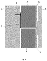
- Fig. 1 shows a cross-section of a particular embodiment of the insulating wall structure described herein.
- the structure comprises a wall (1), which is typically an external wall of a building. On the interior side, the wall is provided with upper and lower VIPs (3, 4), and sheets of other insulation materials (8, 14), all held in place by support profiles (2, 9).
- Fig. 2 shows a detail of the structure around the support profile (2) interposed between the insulation sheets (3).
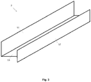
- Fig. 3 is a schematic drawing of the support profile (2) alone.
- the support profile (2) contains a first support face (11) and a second support face (12), interconnected via an intermediate portion (13).
- the profiles (2) are attached to the wall (1) via their first support face (11), using fixation elements (7) such as screws.
- a double faced compressible (e.g. foamed) tape may be provided between the support profile (2) and the wall (1).
- the heads of the screws (7) may be covered with an elastic material such as a compressible foam (not shown).
- the elastic material is provided along the full length of the profile (2).
- the height of the first support face (11) exceeds the height of the second support face (11), thereby facilitating the fixation.
- the profiles (2) are shaped such that they provide upper and lower channels for accommodating the insulation sheets (3, 4, 8, 14).
- Each of the VIPs (3, 4) is provided with a protective panel (6) (see Fig. 2 , not shown in Fig. 1 ).
- the protective panels (6) are also positioned in the channels provided by the support profiles (2, 9).
- the joints between the protective panel (6) and the profile (2) may be sealed, e.g. using a silicone or tape (not shown).
- non-VIP insulation materials (8, 14) are provided at the top and bottom of the wall, although this is optional.
- the top and bottom insulation materials (8, 14) may be the same or different.
- the bottom insulation material (8) is typically mineral wool or the like, thereby facilitating the positioning of conduits and cables (not shown) inside the structure.
- the top insulation material (14) mainly functions to fill the remaining gap between the upper VIP (3) and the ceiling (not shown).
- this insulation material (14) is a non-VIP material which can be cut to the desired size - unlike the VIPs (3, 4).
- the top insulation material (14) can be selected such that it can facilitate the positioning of conduits and cables.
- the insulation materials at the top and bottom are supported by U-shaped support profiles (9), each providing a single channel.
- the support profiles (9) are attached to the wall (1) via fixation means (7) in a similar way as the profile (2) which is interposed between the VIPs (3, 4). Accordingly, no fixation of the lower profile (9) to the floor (15) is needed; and no fixation of the top profile (9) to the ceiling (not shown) is needed.
- a building board (5) covers the remainder of the structure.
- the board (5) is fixed to the second support face (12) of the support profile (2) with an adhesive, e.g. a glue or tape.
- the building board (5) may further be painted, plastered, or otherwise decorated or finished.
- Installation of the insulating wall structure typically starts with installing the bottom profile (9), followed by inserting the lower insulation sheet (14) into the channel provided by the profile. Then, a profile (2) as shown in Fig. 3 is fixed to the wall (1) such that it holds the lower insulation sheet (14) in its lower channel. Then, the first VIP (4) and its corresponding protective panel (6) are inserted in the upper channel provided by the profile (2). Preferably, any visible part of the fixation means (7) is first covered with an elastic material (not shown) for protect the insulation sheet (2) against damaging. A further profile (2) is then provided on the top of the VIP (4) (and corresponding protective panel); and another VIP (3) and its corresponding protective panel (6) are positioned in the channel of that profile (2).
- Fig. 1 shows two rows of VIPs (3, 4), it will be clear to the skilled person that more than two rows of VIPs (or just one row of VIPs) can be used, depending on the sheet size and wall height.
Landscapes
- Engineering & Computer Science (AREA)
- Architecture (AREA)
- Civil Engineering (AREA)
- Structural Engineering (AREA)
- Building Environments (AREA)
Claims (13)
- Structure de mur isolant comprenant:- un mur (1) ;- des premiers et seconds panneaux d'isolation sous vide (VIPs) (3,4) recouvrant des parties adjacentes dudit mur;- un profilé-support (2) comprenant une première face (11) de support fixée au dit mur et une seconde face de support (12), lesdites faces de support étant reliées par une partie intermédiaire (13) qui est interposée entre lesdits premiers et seconds VIPs ; et- un panneau de construction (5) qui est fixé à ladite seconde face (12) de support avec une attache choisie parmi un adhésif ou une attache auto-agrippante caractérisé en ce que chacun desdits VIPs (3,4) est pourvu d'un panneau de protection (6) faisant face audit panneau de construction et dans lequel ledit panneau de protection (6) a une épaisseur comprise entre 1.5 mm et 3.0 mm.
- Structure de mur isolant selon la revendication 1, dans laquelle ledit panneau de protection (6) est constitué ou comprend un ou plusieurs matériaux choisis dans la liste constituée de mélamine, résines phénoliques, métal et polymères aramides.
- Structure de mur isolant selon la revendication 1 ou 2, dans laquelle ledit panneau de protection (6) et lesdits VIP (3,4) sont fournis en pièces séparées.
- Structure de mur isolant selon l'une quelconque des revendications 1 à 3, dans laquelle ledit profilé-support est fait d'un ou plusieurs matériaux choisis dans la liste constituée de polychlorure de vinyle, polyéthylène, polystyrène et polyuréthane.
- Structure de mur isolant selon l'une quelconque des revendications 1 à 4, dans laquelle la distance entre lesdits VIPs (3,4) et ledit panneau de construction (5) est inférieure à 10 mm.
- Structure de mur isolant selon l'une quelconque des revendications 1 à 5, dans laquelle ledit profilé-support (2) est fixé au dit mur avec des vis, dans laquelle les têtes desdites vis sont recouvertes d'un matériau élastique.
- Structure de mur isolant selon l'une quelconque des revendications 1 à 6, dans laquelle sur un côté de ladite portion intermédiaire (13), le premier support (11) s'étend plus loin de la portion intermédiaire que la deuxième face de support.
- Structure de mur isolant selon l'une quelconque des revendications 1 à 7, comprenant en outre une pluralité de profilés-support (2) supportant lesdits VIPs (3,4); chaque profilé-support (2) fournissant une face (12) de support sur laquelle ledit panneau de construction (5) est fixé.
- Structure de mur isolant selon l'une quelconque des revendications 1 à 8, dans laquelle ledit panneau de construction est fait de gypse, de ciment, de fibrociment ou de bois.
- Procédé de revêtement d'un mur, comprenant :(i) le recouvrement d'une partie d'un mur (1) à partir d'un premier panneau d'isolation sous vide (VIP) (4)(ii) la fourniture d'un profilé-support (2), ledit profilé-support comprenant des première et seconde faces de support (11,12) séparées par une partie intermédiaire (13); dans lequel ledit profilé-support (2) est fixé au dit mur via ladite première face (11) de support; et dans lequel- ladite seconde face de support (12), ladite partie intermédiaire (13), et ledit mur (1) et / ou première face de support fournissent un premier canal, ledit premier canal recevant ledit premier VIP;- lesdites première et seconde faces de support et ladite partie intermédiaire foumissent un deuxième canal; et(iii) le positionnement d'un deuxième VIP(3) à l'intérieur dudit deuxième canal, recouvrant ainsi une deuxième partie dudit mur; et(iv) la fourniture à chacun desdits premiers et second VIPs (3,4) d'un panneau de protection (6) ne faisant pas face au dit mur (1), chaque panneau de protection (6) ayant une épaisseur comprise entre 1.5 mm et 3.0 mm ; et(v) la fixation d'un panneau de construction (5) audit profilé-support via sa seconde face de support (12) en utilisant un adhésif, couvrant ainsi lesdits premiers et seconds VIP.
- Procédé selon la revendication 10, dans lequel l'étape (ii) consiste à fixer ledit profilé-support (2) au dit mur avec des vis, puis à recouvrir les têtes desdites vis recouvertes d'un matériau élastique.
- Procédé selon l'une quelconque des revendications 11 à 12, dans lequel la fixation à l'étape (iv) n'implique pas l'utilisation de moyens de fixation perçant ledit panneau de construction.
- A kit pour le revêtement d'un mur, comprenant:- une pluralité de panneaux isolés sous vide (VIP) (3,4) et une pluralité de panneaux de protection (6) ayant une épaisseur entre 1,5 et 3,0 mm- un ou plusieurs profilé-support (2,9), comprenant chacun des première et seconde faces de support séparées par une partie intermédiaire, lesdites faces de support et partie intermédiaire fournissant un deuxième canal; et ladite seconde face de support (12)et ladite partie intermédiaire fournissant un premier canal opposé audit deuxième canal;- un ou plusieurs panneaux de construction (5);- un adhésif pour fixer lesdits un ou plusieurs panneaux de construction audit profilé support.
Applications Claiming Priority (1)
| Application Number | Priority Date | Filing Date | Title |
|---|---|---|---|
| EP17305578.1A EP3404166A1 (fr) | 2017-05-18 | 2017-05-18 | Structure de paroi isolante |
Publications (2)
| Publication Number | Publication Date |
|---|---|
| EP3404167A1 EP3404167A1 (fr) | 2018-11-21 |
| EP3404167B1 true EP3404167B1 (fr) | 2020-07-29 |
Family
ID=58873757
Family Applications (2)
| Application Number | Title | Priority Date | Filing Date |
|---|---|---|---|
| EP17305578.1A Withdrawn EP3404166A1 (fr) | 2017-05-18 | 2017-05-18 | Structure de paroi isolante |
| EP18173000.3A Active EP3404167B1 (fr) | 2017-05-18 | 2018-05-17 | Structure de paroi isolante |
Family Applications Before (1)
| Application Number | Title | Priority Date | Filing Date |
|---|---|---|---|
| EP17305578.1A Withdrawn EP3404166A1 (fr) | 2017-05-18 | 2017-05-18 | Structure de paroi isolante |
Country Status (2)
| Country | Link |
|---|---|
| EP (2) | EP3404166A1 (fr) |
| DK (1) | DK3404167T3 (fr) |
Families Citing this family (2)
| Publication number | Priority date | Publication date | Assignee | Title |
|---|---|---|---|---|
| EP4015724A1 (fr) * | 2020-12-17 | 2022-06-22 | Etex Building Performance International SAS | Support pour panneaux d'isolation |
| FR3134401A1 (fr) * | 2022-04-08 | 2023-10-13 | Construire | Paroi multicouches destinée à recouvrir un mur d’une structure comprenant une couche d’isolant sous vide |
Family Cites Families (8)
| Publication number | Priority date | Publication date | Assignee | Title |
|---|---|---|---|---|
| DE10058501A1 (de) * | 2000-12-07 | 2003-09-04 | Hermann Schnoes | Vakuum-Wärmedämmsystem |
| DE202004004187U1 (de) * | 2004-03-16 | 2005-05-04 | Porextherm-Dämmstoffe Gmbh | Vakuum-Isolations-Paneel |
| DE102004018850B4 (de) * | 2004-04-19 | 2012-01-12 | Energie-Tib Gmbh | Wärmedämmverbundsystem und Verfahren zum Herstellen eines Wärmedämmverbundsystems |
| US7849651B2 (en) * | 2005-05-31 | 2010-12-14 | Kubota Matsushitadenko Exterior Works, Ltd. | Wall materials bracket and insulating wall structure |
| WO2011044696A1 (fr) * | 2009-10-15 | 2011-04-21 | Allan Gillis | Dispositif et procédé de fixation d'un isolant |
| DE102010046639A1 (de) * | 2010-09-25 | 2012-03-29 | Arcelormittal Construction Deutschland Gmbh | Wandaufbau |
| DE102010047242B4 (de) * | 2010-10-04 | 2016-08-04 | Sto Se & Co. Kgaa | Fassadensystem |
| SI24327A (sl) * | 2013-03-14 | 2014-09-30 | Intech-Les, Razvojni Center, D.O.O. | Sidra za pritrjevanje toplotne izolacije iz VIP panelov ali VISE kompozitnih plošč v fasadnih in drugih sistemih in postopek pritrjevanja |
-
2017
- 2017-05-18 EP EP17305578.1A patent/EP3404166A1/fr not_active Withdrawn
-
2018
- 2018-05-17 DK DK18173000.3T patent/DK3404167T3/da active
- 2018-05-17 EP EP18173000.3A patent/EP3404167B1/fr active Active
Non-Patent Citations (1)
| Title |
|---|
| None * |
Also Published As
| Publication number | Publication date |
|---|---|
| EP3404166A1 (fr) | 2018-11-21 |
| DK3404167T3 (da) | 2020-09-21 |
| EP3404167A1 (fr) | 2018-11-21 |
Similar Documents
| Publication | Publication Date | Title |
|---|---|---|
| US11142904B2 (en) | Continuous wall assemblies and methods | |
| EP1989362B1 (fr) | Système d'isolation comprenant des panneaux d'isolation interconnectés disposés contre un mur | |
| CA2850715C (fr) | Systemes de paroi a coupure thermique et pince reglable thermique | |
| CA2670509C (fr) | Ensemble mural a isolation continue | |
| US6516578B1 (en) | Thin brick panel system | |
| EP2800846B1 (fr) | Façade | |
| US10179996B2 (en) | Façade structure | |
| US20160053494A1 (en) | Thermal Break Wall Systems And Thermal Adjustable Clip | |
| GB2448614A (en) | Composite cladding panel with ventilation passageways | |
| EP3404167B1 (fr) | Structure de paroi isolante | |
| EA025741B1 (ru) | Теплоизоляционный элемент для изоляции фасадов зданий, теплоизоляционная композитная система и способ производства теплоизоляционной композитной системы | |
| EP2210991B1 (fr) | Système d'isolation murale externe | |
| JP2004204606A (ja) | 建築用パネルおよび建物の断熱構造 | |
| JPH11117432A (ja) | 外壁断熱パネル構造およびパネル材 | |
| JP3993682B2 (ja) | Alc外壁の改修工法 | |
| JPH0330482Y2 (fr) | ||
| JP2587519Y2 (ja) | 屋内配管用サポート | |
| CA2978938A1 (fr) | Systemes et methodes ameliores destines a des panneaux ignifuges | |
| JP2003232118A (ja) | Alc外壁の改修工法 | |
| JPH07189408A (ja) | Alc壁面構造 | |
| JP2009270271A (ja) | 断熱壁 | |
| JPH11223027A (ja) | Alc外壁の改修構造 |
Legal Events
| Date | Code | Title | Description |
|---|---|---|---|
| PUAI | Public reference made under article 153(3) epc to a published international application that has entered the european phase |
Free format text: ORIGINAL CODE: 0009012 |
|
| STAA | Information on the status of an ep patent application or granted ep patent |
Free format text: STATUS: THE APPLICATION HAS BEEN PUBLISHED |
|
| AK | Designated contracting states |
Kind code of ref document: A1 Designated state(s): AL AT BE BG CH CY CZ DE DK EE ES FI FR GB GR HR HU IE IS IT LI LT LU LV MC MK MT NL NO PL PT RO RS SE SI SK SM TR |
|
| AX | Request for extension of the european patent |
Extension state: BA ME |
|
| STAA | Information on the status of an ep patent application or granted ep patent |
Free format text: STATUS: REQUEST FOR EXAMINATION WAS MADE |
|
| 17P | Request for examination filed |
Effective date: 20190520 |
|
| RBV | Designated contracting states (corrected) |
Designated state(s): AL AT BE BG CH CY CZ DE DK EE ES FI FR GB GR HR HU IE IS IT LI LT LU LV MC MK MT NL NO PL PT RO RS SE SI SK SM TR |
|
| GRAP | Despatch of communication of intention to grant a patent |
Free format text: ORIGINAL CODE: EPIDOSNIGR1 |
|
| STAA | Information on the status of an ep patent application or granted ep patent |
Free format text: STATUS: GRANT OF PATENT IS INTENDED |
|
| INTG | Intention to grant announced |
Effective date: 20191018 |
|
| GRAJ | Information related to disapproval of communication of intention to grant by the applicant or resumption of examination proceedings by the epo deleted |
Free format text: ORIGINAL CODE: EPIDOSDIGR1 |
|
| STAA | Information on the status of an ep patent application or granted ep patent |
Free format text: STATUS: REQUEST FOR EXAMINATION WAS MADE |
|
| GRAP | Despatch of communication of intention to grant a patent |
Free format text: ORIGINAL CODE: EPIDOSNIGR1 |
|
| STAA | Information on the status of an ep patent application or granted ep patent |
Free format text: STATUS: GRANT OF PATENT IS INTENDED |
|
| INTG | Intention to grant announced |
Effective date: 20200221 |
|
| GRAS | Grant fee paid |
Free format text: ORIGINAL CODE: EPIDOSNIGR3 |
|
| GRAA | (expected) grant |
Free format text: ORIGINAL CODE: 0009210 |
|
| STAA | Information on the status of an ep patent application or granted ep patent |
Free format text: STATUS: THE PATENT HAS BEEN GRANTED |
|
| AK | Designated contracting states |
Kind code of ref document: B1 Designated state(s): AL AT BE BG CH CY CZ DE DK EE ES FI FR GB GR HR HU IE IS IT LI LT LU LV MC MK MT NL NO PL PT RO RS SE SI SK SM TR |
|
| REG | Reference to a national code |
Ref country code: CH Ref legal event code: EP |
|
| REG | Reference to a national code |
Ref country code: DE Ref legal event code: R096 Ref document number: 602018006361 Country of ref document: DE |
|
| REG | Reference to a national code |
Ref country code: AT Ref legal event code: REF Ref document number: 1295963 Country of ref document: AT Kind code of ref document: T Effective date: 20200815 |
|
| REG | Reference to a national code |
Ref country code: IE Ref legal event code: FG4D |
|
| REG | Reference to a national code |
Ref country code: NL Ref legal event code: FP |
|
| REG | Reference to a national code |
Ref country code: DK Ref legal event code: T3 Effective date: 20200914 |
|
| REG | Reference to a national code |
Ref country code: SE Ref legal event code: TRGR |
|
| REG | Reference to a national code |
Ref country code: LT Ref legal event code: MG4D |
|
| PG25 | Lapsed in a contracting state [announced via postgrant information from national office to epo] |
Ref country code: NO Free format text: LAPSE BECAUSE OF FAILURE TO SUBMIT A TRANSLATION OF THE DESCRIPTION OR TO PAY THE FEE WITHIN THE PRESCRIBED TIME-LIMIT Effective date: 20201029 Ref country code: ES Free format text: LAPSE BECAUSE OF FAILURE TO SUBMIT A TRANSLATION OF THE DESCRIPTION OR TO PAY THE FEE WITHIN THE PRESCRIBED TIME-LIMIT Effective date: 20200729 Ref country code: BG Free format text: LAPSE BECAUSE OF FAILURE TO SUBMIT A TRANSLATION OF THE DESCRIPTION OR TO PAY THE FEE WITHIN THE PRESCRIBED TIME-LIMIT Effective date: 20201029 Ref country code: LT Free format text: LAPSE BECAUSE OF FAILURE TO SUBMIT A TRANSLATION OF THE DESCRIPTION OR TO PAY THE FEE WITHIN THE PRESCRIBED TIME-LIMIT Effective date: 20200729 Ref country code: HR Free format text: LAPSE BECAUSE OF FAILURE TO SUBMIT A TRANSLATION OF THE DESCRIPTION OR TO PAY THE FEE WITHIN THE PRESCRIBED TIME-LIMIT Effective date: 20200729 Ref country code: PT Free format text: LAPSE BECAUSE OF FAILURE TO SUBMIT A TRANSLATION OF THE DESCRIPTION OR TO PAY THE FEE WITHIN THE PRESCRIBED TIME-LIMIT Effective date: 20201130 Ref country code: GR Free format text: LAPSE BECAUSE OF FAILURE TO SUBMIT A TRANSLATION OF THE DESCRIPTION OR TO PAY THE FEE WITHIN THE PRESCRIBED TIME-LIMIT Effective date: 20201030 Ref country code: FI Free format text: LAPSE BECAUSE OF FAILURE TO SUBMIT A TRANSLATION OF THE DESCRIPTION OR TO PAY THE FEE WITHIN THE PRESCRIBED TIME-LIMIT Effective date: 20200729 |
|
| PG25 | Lapsed in a contracting state [announced via postgrant information from national office to epo] |
Ref country code: RS Free format text: LAPSE BECAUSE OF FAILURE TO SUBMIT A TRANSLATION OF THE DESCRIPTION OR TO PAY THE FEE WITHIN THE PRESCRIBED TIME-LIMIT Effective date: 20200729 Ref country code: PL Free format text: LAPSE BECAUSE OF FAILURE TO SUBMIT A TRANSLATION OF THE DESCRIPTION OR TO PAY THE FEE WITHIN THE PRESCRIBED TIME-LIMIT Effective date: 20200729 Ref country code: LV Free format text: LAPSE BECAUSE OF FAILURE TO SUBMIT A TRANSLATION OF THE DESCRIPTION OR TO PAY THE FEE WITHIN THE PRESCRIBED TIME-LIMIT Effective date: 20200729 Ref country code: IS Free format text: LAPSE BECAUSE OF FAILURE TO SUBMIT A TRANSLATION OF THE DESCRIPTION OR TO PAY THE FEE WITHIN THE PRESCRIBED TIME-LIMIT Effective date: 20201129 |
|
| PG25 | Lapsed in a contracting state [announced via postgrant information from national office to epo] |
Ref country code: SM Free format text: LAPSE BECAUSE OF FAILURE TO SUBMIT A TRANSLATION OF THE DESCRIPTION OR TO PAY THE FEE WITHIN THE PRESCRIBED TIME-LIMIT Effective date: 20200729 Ref country code: IT Free format text: LAPSE BECAUSE OF FAILURE TO SUBMIT A TRANSLATION OF THE DESCRIPTION OR TO PAY THE FEE WITHIN THE PRESCRIBED TIME-LIMIT Effective date: 20200729 Ref country code: EE Free format text: LAPSE BECAUSE OF FAILURE TO SUBMIT A TRANSLATION OF THE DESCRIPTION OR TO PAY THE FEE WITHIN THE PRESCRIBED TIME-LIMIT Effective date: 20200729 Ref country code: RO Free format text: LAPSE BECAUSE OF FAILURE TO SUBMIT A TRANSLATION OF THE DESCRIPTION OR TO PAY THE FEE WITHIN THE PRESCRIBED TIME-LIMIT Effective date: 20200729 Ref country code: CZ Free format text: LAPSE BECAUSE OF FAILURE TO SUBMIT A TRANSLATION OF THE DESCRIPTION OR TO PAY THE FEE WITHIN THE PRESCRIBED TIME-LIMIT Effective date: 20200729 |
|
| REG | Reference to a national code |
Ref country code: DE Ref legal event code: R097 Ref document number: 602018006361 Country of ref document: DE |
|
| PG25 | Lapsed in a contracting state [announced via postgrant information from national office to epo] |
Ref country code: AL Free format text: LAPSE BECAUSE OF FAILURE TO SUBMIT A TRANSLATION OF THE DESCRIPTION OR TO PAY THE FEE WITHIN THE PRESCRIBED TIME-LIMIT Effective date: 20200729 |
|
| PLBE | No opposition filed within time limit |
Free format text: ORIGINAL CODE: 0009261 |
|
| STAA | Information on the status of an ep patent application or granted ep patent |
Free format text: STATUS: NO OPPOSITION FILED WITHIN TIME LIMIT |
|
| REG | Reference to a national code |
Ref country code: AT Ref legal event code: UEP Ref document number: 1295963 Country of ref document: AT Kind code of ref document: T Effective date: 20200729 |
|
| PG25 | Lapsed in a contracting state [announced via postgrant information from national office to epo] |
Ref country code: SK Free format text: LAPSE BECAUSE OF FAILURE TO SUBMIT A TRANSLATION OF THE DESCRIPTION OR TO PAY THE FEE WITHIN THE PRESCRIBED TIME-LIMIT Effective date: 20200729 |
|
| 26N | No opposition filed |
Effective date: 20210430 |
|
| PG25 | Lapsed in a contracting state [announced via postgrant information from national office to epo] |
Ref country code: SI Free format text: LAPSE BECAUSE OF FAILURE TO SUBMIT A TRANSLATION OF THE DESCRIPTION OR TO PAY THE FEE WITHIN THE PRESCRIBED TIME-LIMIT Effective date: 20200729 |
|
| REG | Reference to a national code |
Ref country code: CH Ref legal event code: PL |
|
| PG25 | Lapsed in a contracting state [announced via postgrant information from national office to epo] |
Ref country code: MC Free format text: LAPSE BECAUSE OF FAILURE TO SUBMIT A TRANSLATION OF THE DESCRIPTION OR TO PAY THE FEE WITHIN THE PRESCRIBED TIME-LIMIT Effective date: 20200729 Ref country code: LU Free format text: LAPSE BECAUSE OF NON-PAYMENT OF DUE FEES Effective date: 20210517 Ref country code: LI Free format text: LAPSE BECAUSE OF NON-PAYMENT OF DUE FEES Effective date: 20210531 Ref country code: CH Free format text: LAPSE BECAUSE OF NON-PAYMENT OF DUE FEES Effective date: 20210531 |
|
| PGFP | Annual fee paid to national office [announced via postgrant information from national office to epo] |
Ref country code: TR Payment date: 20230316 Year of fee payment: 6 |
|
| PG25 | Lapsed in a contracting state [announced via postgrant information from national office to epo] |
Ref country code: CY Free format text: LAPSE BECAUSE OF FAILURE TO SUBMIT A TRANSLATION OF THE DESCRIPTION OR TO PAY THE FEE WITHIN THE PRESCRIBED TIME-LIMIT Effective date: 20200729 |
|
| P01 | Opt-out of the competence of the unified patent court (upc) registered |
Effective date: 20230619 |
|
| PG25 | Lapsed in a contracting state [announced via postgrant information from national office to epo] |
Ref country code: HU Free format text: LAPSE BECAUSE OF FAILURE TO SUBMIT A TRANSLATION OF THE DESCRIPTION OR TO PAY THE FEE WITHIN THE PRESCRIBED TIME-LIMIT; INVALID AB INITIO Effective date: 20180517 |
|
| PGFP | Annual fee paid to national office [announced via postgrant information from national office to epo] |
Ref country code: NL Payment date: 20230519 Year of fee payment: 6 Ref country code: IE Payment date: 20230522 Year of fee payment: 6 Ref country code: FR Payment date: 20230526 Year of fee payment: 6 Ref country code: DK Payment date: 20230524 Year of fee payment: 6 Ref country code: DE Payment date: 20230519 Year of fee payment: 6 |
|
| PGFP | Annual fee paid to national office [announced via postgrant information from national office to epo] |
Ref country code: SE Payment date: 20230420 Year of fee payment: 6 Ref country code: AT Payment date: 20230522 Year of fee payment: 6 |
|
| PGFP | Annual fee paid to national office [announced via postgrant information from national office to epo] |
Ref country code: BE Payment date: 20230519 Year of fee payment: 6 |
|
| PGFP | Annual fee paid to national office [announced via postgrant information from national office to epo] |
Ref country code: GB Payment date: 20230524 Year of fee payment: 6 |
|
| PG25 | Lapsed in a contracting state [announced via postgrant information from national office to epo] |
Ref country code: MK Free format text: LAPSE BECAUSE OF FAILURE TO SUBMIT A TRANSLATION OF THE DESCRIPTION OR TO PAY THE FEE WITHIN THE PRESCRIBED TIME-LIMIT Effective date: 20200729 |