EP3404164A1 - A sealing collar - Google Patents
A sealing collar Download PDFInfo
- Publication number
- EP3404164A1 EP3404164A1 EP18172234.9A EP18172234A EP3404164A1 EP 3404164 A1 EP3404164 A1 EP 3404164A1 EP 18172234 A EP18172234 A EP 18172234A EP 3404164 A1 EP3404164 A1 EP 3404164A1
- Authority
- EP
- European Patent Office
- Prior art keywords
- sealing collar
- inner portion
- condition
- insulating elements
- inner edge
- Prior art date
- Legal status (The legal status is an assumption and is not a legal conclusion. Google has not performed a legal analysis and makes no representation as to the accuracy of the status listed.)
- Granted
Links
Images


Classifications
-
- E—FIXED CONSTRUCTIONS
- E04—BUILDING
- E04D—ROOF COVERINGS; SKY-LIGHTS; GUTTERS; ROOF-WORKING TOOLS
- E04D13/00—Special arrangements or devices in connection with roof coverings; Protection against birds; Roof drainage ; Sky-lights
- E04D13/03—Sky-lights; Domes; Ventilating sky-lights
- E04D13/0305—Supports or connecting means for sky-lights of flat or domed shape
-
- E—FIXED CONSTRUCTIONS
- E04—BUILDING
- E04D—ROOF COVERINGS; SKY-LIGHTS; GUTTERS; ROOF-WORKING TOOLS
- E04D13/00—Special arrangements or devices in connection with roof coverings; Protection against birds; Roof drainage ; Sky-lights
- E04D13/14—Junctions of roof sheathings to chimneys or other parts extending above the roof
- E04D13/147—Junctions of roof sheathings to chimneys or other parts extending above the roof specially adapted for inclined roofs
- E04D13/1473—Junctions of roof sheathings to chimneys or other parts extending above the roof specially adapted for inclined roofs specially adapted to the cross-section of the parts extending above the roof
- E04D13/1475—Junctions of roof sheathings to chimneys or other parts extending above the roof specially adapted for inclined roofs specially adapted to the cross-section of the parts extending above the roof wherein the parts extending above the roof have a generally rectangular cross-section
-
- E—FIXED CONSTRUCTIONS
- E04—BUILDING
- E04D—ROOF COVERINGS; SKY-LIGHTS; GUTTERS; ROOF-WORKING TOOLS
- E04D13/00—Special arrangements or devices in connection with roof coverings; Protection against birds; Roof drainage ; Sky-lights
- E04D13/14—Junctions of roof sheathings to chimneys or other parts extending above the roof
- E04D13/147—Junctions of roof sheathings to chimneys or other parts extending above the roof specially adapted for inclined roofs
-
- E—FIXED CONSTRUCTIONS
- E04—BUILDING
- E04D—ROOF COVERINGS; SKY-LIGHTS; GUTTERS; ROOF-WORKING TOOLS
- E04D1/00—Roof covering by making use of tiles, slates, shingles, or other small roofing elements
- E04D1/36—Devices for sealing the spaces or joints between roof-covering elements
-
- E—FIXED CONSTRUCTIONS
- E04—BUILDING
- E04D—ROOF COVERINGS; SKY-LIGHTS; GUTTERS; ROOF-WORKING TOOLS
- E04D13/00—Special arrangements or devices in connection with roof coverings; Protection against birds; Roof drainage ; Sky-lights
- E04D13/03—Sky-lights; Domes; Ventilating sky-lights
-
- E—FIXED CONSTRUCTIONS
- E04—BUILDING
- E04D—ROOF COVERINGS; SKY-LIGHTS; GUTTERS; ROOF-WORKING TOOLS
- E04D13/00—Special arrangements or devices in connection with roof coverings; Protection against birds; Roof drainage ; Sky-lights
- E04D13/03—Sky-lights; Domes; Ventilating sky-lights
- E04D13/0305—Supports or connecting means for sky-lights of flat or domed shape
- E04D13/031—Supports or connecting means for sky-lights of flat or domed shape characterised by a frame for connection to an inclined roof
Definitions
- the present invention relates to a sealing collar adapted for being mounted around a window frame mounted in an inclined roof of a building, said sealing collar comprising an inner portion and an outer skirt portion, said inner portion having top, bottom and side members, where said inner portion has an inner edge and an outer edge opposite the inner edge, where said inner edge defines an opening when the sealing collar is in the mounted condition, where said inner portion is adapted for surrounding a window frame by the inner edge, where the top, bottom and side members of the inner portion are made from a substantially dimensionally stable material, and where shape and size of the opening substantially matches shape and size of the window frame, when the sealing collar is in the mounted condition.
- a sealing collar also known as an underroof collar is applied.
- Such a sealing collar is known from the applicant's EP patent no 0 994 992 B1 .
- the sealing collar is installed after the window frame, and possibly an insulating frame, has been installed in the opening. During the installation, the sealing collar is pulled over the window frame and the inner portion is attached to the outer side of the window frame. The outer skirt extends over the underroof. To prevent water leakage into the opening, the sealing collar must be in close engagement with the outer side of the window frame and the underroof of the roof structure.
- the outer skirt portion of the sealing collar is susceptible to being damage during transport or installation. Damage to the outer skirt portion potentially means that water leakage cannot be prevented.
- a sealing collar of the kind mentioned in the introduction which is furthermore characterized in that the outer skirt portion has a delivery condition, where it is packed up and attached to a member of the inner portion, and an installed condition, where it is unpacked and extends over the inner portion and is attached to the inner portion, where said outer skirt portion is a waterproof membrane adapted for forming a waterproof transition to an underroof of the inclined roof.
- the outer skirt portion can be maintained in the delivery condition during transportation and subsequent installation. When there is reduced or no risk of damaging the outer skirt portion it can be brought to the installed condition.
- the outer skirt portion may be provided rolled up in the delivery condition, and maintained in this condition by fastening means such as string, Velcro or similar.
- the outer skirt portion may then be brought from the delivery condition to the installed condition by way of removing the fastening means, whereby the outer skirt portion may be rolled over the inner portion.
- the transition from the delivery condition to the installed condition may be performed manually by rolling out the outer skirt portion. Alternatively, the transition may occur automatically due to tension or gravity.
- the outer skirt portion may be provided in a folded manner, whereby the unfolding provides the proper installation.
- the outer skirt portion may be provided in a pleated manner, whereby it may be adapted to expand and engage with roof battens of the roof.
- the outer skirt portion may have dimensions such that it matches the outer edge of the inner portion.
- the outer skirt portion may have dimensions larger than the outer edge of the inner portion allowing for in situ modifications.
- the outer skirt portion may be attached to the inner portion at several points along the circumference of the inner portion when in the installed condition.
- sealing collar need not to be identical.
- a sealing collar where there is no outer skirt portion at one side may be employed where two windows are mounted closely side-by-side.
- a sealing collar of the kind mentioned in the introduction which is furthermore characterized in that the sealing collar further comprises a stabilizing portion with outer dimensions substantially matching the shape and size of the opening, where the stabilizing portion is arranged at the inner edge of the inner portion and the stabilizing portion is attached to the inner edge of the inner portion at a plurality of points, whereby the inner portion is urged to maintain its desired dimensions in the mounted condition.
- the stabilizing portion ensures that the inner portion cannot be skewed before or during the installation, thereby reducing the risk of erroneous installation.
- the stabilizing portion may be made from cardboard, wood or roofing felt.
- the stabilizing portion may have an opening arranged centrally allowing for a person to reach through the opening when the sealing collar is mounted on a roof or during mounting.
- the stabilizing portion may be attached to the inner portion using adhesives, a weld or a staple.
- the inner portion and the stabilizing portion may be made as a single entity, where a part of the material is perforated to form a cutting indication and the unperforated material forms the plurality of points.
- the stabilizing portion may also be attached to the inner portion by use of friction.
- the stabilizing portion may be removed before the opening is cut or it may be maintained as a cutting indication, after the inner portion has been mounted on the roof.
- the stabilizing portion may be removed by hand or alternatively it may have to be cut from the inner portion.
- the outer skirt may be provided attached to the inner portion, whereby easier handling of such an embodiment is facilitated compared to if the outer skirt portion was provided unattached.
- the sealing collar further comprises a flap for holding a tool.
- the flap may be provided as a cutout, that can be moved to extend from the sealing collar for holding the tool, and can be moved to fit flush with the sealing collar when unused.
- the flap may be provided as material extending from the sealing collar.
- the flap may be provided in a hook shape, whereby a hammer can be hung from its head or a staple gun from its handle.
- a spirit level may be placed on the sealing collar, whereby an easy method to ensure that the sealing collar is level is facilitated.
- the sealing collar further comprises a flap for attaching the sealing collar to the roof.
- the flap may be attached to a roof batten or rafter. This may be achieved by providing the flap in a hook shape, whereby the flap can be brought into engagement with a batten or rafter. Alternatively, such engagement may be achieved by bending material of the sealing collar around a rafter or batten.
- the flap may be provided as a cutout that can be moved to extend from the sealing collar, and can be moved to fit flush with the sealing collar when unused.
- the sealing collar further includes one or more first insulating elements.
- the opening cut in the roof can readily be made thermally insulated, by arranging the first insulating elements in the opening cut in the roof.
- the first insulating elements may be provided integrally formed with the sealing collar or provided for in situ installation.
- the first insulating elements may be provided attached to the inner portion using mesh or web, allowing them to be turned from the outer edge of the inner portion to the inner edge of the inner portion.
- the first insulating elements may be arranged partially or fully along the inner edge of the inner portion.
- the first insulating elements may be arranged on the inner portion.
- the first insulating elements may be provided attached to the inner edge of the inner portion.
- the first insulating elements may be provided as a single uniform piece or as multiple individual pieces.
- the one or more first insulating elements has a delivery condition, where the one or more first insulating elements are packed up, and an installed condition, where the one or more first insulating are arranged along the inner edge of the inner portion.
- Examples of the delivery condition may be that the one or more first insulating elements being arranged on the outer edge of the inner portion, the one or more first insulating elements being collapsed into a single package and being attached to the inner portion or as being collapsed into a single package not being attached to the inner portion.
- the transition from the delivery condition to the installed condition may be exemplified as a manually unpacking of the one or more insulating elements.
- the transition may be provided as an automatic or a semi-automatic unpacking of the one or more first insulating elements, provided by elastic or spring elements, where the one or more first insulating elements automatically obtains the desired shape of either the inner portion or the inner edge of the inner portion.
- the sealing collar further comprises a flap for holding the one or more first insulating elements in an intermediate condition between the delivery and the installed condition.
- the intermediate condition may be exemplified as the one or more first insulating elements being held on the outer edge of the inner portion or that the one or more first insulating element are held onto the inner portion.
- the flap may be provided as a cutout that can be moved to extend from the sealing collar, and can be moved to fit flush with the sealing collar when unused.
- the flap may be provided in a hook shape, whereby the insulating elements can be held.
- the sealing collar may comprises one or more second insulating elements intended to be arranged in the plane of the roof/sealing collar/flashing.
- the one or more second insulating elements may be provided attached to the inner portion, or to the one or more first insulating elements.
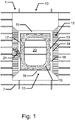
- Fig. 1 shows an embodiment of the sealing collar 10 installed on a roof 1.
- the sealing collar 10 comprising an inner portion 11 and an outer skirt portion 12.
- the inner portion having top 15, bottom 16 and side members 17, 18, where said inner portion 11 has an inner edge 13 and an outer edge 14 opposite the inner edge 13.
- Said inner edge 13 defines an opening 20 when the sealing collar 10 is in the mounted condition, where said inner portion 11 is adapted for surrounding a window frame by the inner edge 13.
- the top 15, bottom 16 and side members 17, 18 of the inner portion 11 are made from a substantially dimensionally stable material.
- the shape and size of the opening 20 substantially matches the shape and size of the window frame, when the sealing collar 10 is in the mounted condition.
- the sealing collar 10 further comprises a stabilizing portion 19 with outer dimensions substantially matching the shape and size of the opening 20, where the stabilizing portion 19 is arranged at the inner edge 13 of the inner portion 11.
- the stabilizing portion 19 is attached to the inner edge 13 of the inner portion 11 at a plurality of points, whereby the inner portion 11 is urged to maintain its desired dimensions in the mounted condition.
- the outer skirt portion 12 is mounted at the outer edge 14 of the inner portion 11. An opening in the roof 1 is cut by having the saw 21 follow the inner edge 13 of the inner portion 11.
- Fig. 2a shows an embodiment of the sealing collar 10, where the outer skirt portion 12 is mounted at the outer edge of the inner portion 11.
- the sealing collar 10 also comprises first insulating elements 4 in the delivery condition, where the first insulating elements 4 are collapsed and attached to the outer skirt portion 12 by fastening means.
- the second insulating elements 41 is attached to the first insulating element 4.
- the sealing collar further comprises a stabilizing portion 19 which has an opening 21 arranged centrally. The opening 21 allows a user to reach through when the sealing collar 10 is mounted on the roof or during mounting.
- Fig. 2b shows an embodiment of the sealing collar 10, where the outer skirt portion 12 is attached at the outer edge of the inner portion 11.
- the first insulation elements 4 is collapsed in the delivery condition and attached to the side member of the inner portion 11.
- the second insulating elements 41 are mounted on the outer edge of the inner portion 11 and the outer skirt portion 12.
- Fig. 2c shows an embodiment of the sealing collar 10, where the outer skirt portion 12 is in the delivery condition.
- the outer skirt 12 is folded onto itself and attached to the inner portion 11.
- the first insulating elements 4 are collapsed in the delivery condition and attached to the inner portion 11.
- the second insulating elements 41 are attached to the first insulating elements 4.
- Fig. 2d shows an embodiment of the sealing collar 10, where the outer skirt portion 12 is folded in the delivery condition and the second insulating elements 41 are attached to it.
- the first insulating elements 4 are collapsed in the delivery condition and attached to the side member of the inner portion 11.
- Fig. 2e shows an embodiment of the sealing collar 10, where the outer skirt portion 12 is rolled onto itself and in the delivery condition.
- the first insulating elements 4 are collapsed in the delivery condition and attached to the side member of the inner portion 11.
- the second insulating elements 41 are attached to the first insulating elements 4.
- Fig. 2f shows an embodiment of the sealing collar 10, where the outer skirt portion 12 is rolled onto itself and in the delivery condition.
- the first insulating elements 4 are collapsed in the delivery condition and attached to the bottom member of the inner portion 11.
- the second insulating elements 41 are attached to the first insulating elements 4.
- Fig. 2g shows an embodiment of the sealing collar 10, where the outer skirt portion 12 is rolled onto itself and in the delivery condition.
- the first insulating elements 4 are collapsed in the delivery condition and attached to the side member of the inner portion 11.
- the second insulating elements 41 are collapsed into the delivery condition and attached to the opposite side member of the inner portion 11.
- Fig. 2h shows an embodiment of the sealing collar 10, where the outer skirt portion 12 is rolled onto itself and in the delivery condition.
- the first insulating elements 4 are mounted on the inner portion 11.
- the second insulating elements 41 are mounted the inner portion 11.
Landscapes
- Engineering & Computer Science (AREA)
- Architecture (AREA)
- Civil Engineering (AREA)
- Structural Engineering (AREA)
- Roof Covering Using Slabs Or Stiff Sheets (AREA)
- Building Environments (AREA)
- Packaging Of Machine Parts And Wound Products (AREA)
- Seal Device For Vehicle (AREA)
Abstract
Description
- The present invention relates to a sealing collar adapted for being mounted around a window frame mounted in an inclined roof of a building, said sealing collar comprising an inner portion and an outer skirt portion,
said inner portion having top, bottom and side members, where said inner portion has an inner edge and an outer edge opposite the inner edge, where said inner edge defines an opening when the sealing collar is in the mounted condition, where said inner portion is adapted for surrounding a window frame by the inner edge, where the top, bottom and side members of the inner portion are made from a substantially dimensionally stable material, and where shape and size of the opening substantially matches shape and size of the window frame, when the sealing collar is in the mounted condition. - During the installation of a window in an inclined roof including an underroof, an opening for the window frame is cut in roof battens and the underroof. In order to make the transition between the installed window frame and the underroof waterproof and prevent water leakage into the roof construction, a sealing collar also known as an underroof collar is applied. Such a sealing collar is known from the applicant's
EP patent no 0 994 992 B1 . - The sealing collar is installed after the window frame, and possibly an insulating frame, has been installed in the opening. During the installation, the sealing collar is pulled over the window frame and the inner portion is attached to the outer side of the window frame. The outer skirt extends over the underroof. To prevent water leakage into the opening, the sealing collar must be in close engagement with the outer side of the window frame and the underroof of the roof structure.
- The outer skirt portion of the sealing collar is susceptible to being damage during transport or installation. Damage to the outer skirt portion potentially means that water leakage cannot be prevented.
- Furthermore, under the risk of damaging the outer skirt portion, extra care must be taken not to damage the outer skirt portion during installation. This leads to an inefficient installation process.
- It is an object of the invention to provide a sealing collar, which facilitates the installation process and reduces the risk of error during installation.
- Furthermore, it may be a problem to ensure that an opening with the right dimensions is cut in the roof.
- It is therefore a second object of the invention to provide a sealing collar, which facilitates the installation process.
- In a first aspect of the invention, at least the first object is met by a sealing collar of the kind mentioned in the introduction, which is furthermore characterized in that the outer skirt portion has a delivery condition, where it is packed up and attached to a member of the inner portion, and an installed condition, where it is unpacked and extends over the inner portion and is attached to the inner portion, where said outer skirt portion is a waterproof membrane adapted for forming a waterproof transition to an underroof of the inclined roof.
- Consequently, the outer skirt portion can be maintained in the delivery condition during transportation and subsequent installation. When there is reduced or no risk of damaging the outer skirt portion it can be brought to the installed condition.
- The outer skirt portion may be provided rolled up in the delivery condition, and maintained in this condition by fastening means such as string, Velcro or similar. The outer skirt portion may then be brought from the delivery condition to the installed condition by way of removing the fastening means, whereby the outer skirt portion may be rolled over the inner portion. The transition from the delivery condition to the installed condition may be performed manually by rolling out the outer skirt portion. Alternatively, the transition may occur automatically due to tension or gravity.
- The outer skirt portion may be provided in a folded manner, whereby the unfolding provides the proper installation.
- The outer skirt portion may be provided in a pleated manner, whereby it may be adapted to expand and engage with roof battens of the roof.
- The outer skirt portion may have dimensions such that it matches the outer edge of the inner portion. Alternatively, the outer skirt portion may have dimensions larger than the outer edge of the inner portion allowing for in situ modifications. By providing the outer skirt portion in a pleated manner it is possible to perform in situ modifications, whereby the excess material allows for modification of the dimensions.
- The outer skirt portion may be attached to the inner portion at several points along the circumference of the inner portion when in the installed condition.
- The two sides of the sealing collar need not to be identical. As an example a sealing collar, where there is no outer skirt portion at one side may be employed where two windows are mounted closely side-by-side.
- In a second aspect of the invention, the second and further objects are met by a sealing collar of the kind mentioned in the introduction, which is furthermore characterized in that the sealing collar further comprises a stabilizing portion with outer dimensions substantially matching the shape and size of the opening, where the stabilizing portion is arranged at the inner edge of the inner portion and the stabilizing portion is attached to the inner edge of the inner portion at a plurality of points, whereby the inner portion is urged to maintain its desired dimensions in the mounted condition.
- Consequently, the stabilizing portion ensures that the inner portion cannot be skewed before or during the installation, thereby reducing the risk of erroneous installation.
- The stabilizing portion may be made from cardboard, wood or roofing felt.
- The stabilizing portion may have an opening arranged centrally allowing for a person to reach through the opening when the sealing collar is mounted on a roof or during mounting.
- The stabilizing portion may be attached to the inner portion using adhesives, a weld or a staple. Alternatively, the inner portion and the stabilizing portion may be made as a single entity, where a part of the material is perforated to form a cutting indication and the unperforated material forms the plurality of points. The stabilizing portion may also be attached to the inner portion by use of friction.
- The stabilizing portion may be removed before the opening is cut or it may be maintained as a cutting indication, after the inner portion has been mounted on the roof.
- The stabilizing portion may be removed by hand or alternatively it may have to be cut from the inner portion.
- The outer skirt may be provided attached to the inner portion, whereby easier handling of such an embodiment is facilitated compared to if the outer skirt portion was provided unattached.
- In some embodiments the sealing collar further comprises a flap for holding a tool.
- Consequently, an easier installation method is provided as a tool can be conveniently positioned within reach of the user on the sealing collar.
- The flap may be provided as a cutout, that can be moved to extend from the sealing collar for holding the tool, and can be moved to fit flush with the sealing collar when unused.
- The flap may be provided as material extending from the sealing collar.
- The flap may be provided in a hook shape, whereby a hammer can be hung from its head or a staple gun from its handle.
- Furthermore, a spirit level may be placed on the sealing collar, whereby an easy method to ensure that the sealing collar is level is facilitated.
- This may be achieved by having two flaps arranged along a line of the sealing collar, which is intended to be horizontal. By resting each end of the spirit level on each flap, the orientation of the sealing collar and the spirit level will be coupled/linked.
- In some embodiments the sealing collar further comprises a flap for attaching the sealing collar to the roof.
- Consequently, a preliminary and reversible attachment of the sealing collar is provided, whereby the sealing collar can be arranged to the desired position and maintained in that position, while attaching the sealing collar to the roof using more permanent means.
- The flap may be attached to a roof batten or rafter. This may be achieved by providing the flap in a hook shape, whereby the flap can be brought into engagement with a batten or rafter. Alternatively, such engagement may be achieved by bending material of the sealing collar around a rafter or batten.
- The flap may be provided as a cutout that can be moved to extend from the sealing collar, and can be moved to fit flush with the sealing collar when unused.
- In some embodiments the sealing collar further includes one or more first insulating elements.
- Consequently, the opening cut in the roof can readily be made thermally insulated, by arranging the first insulating elements in the opening cut in the roof.
- The first insulating elements may be provided integrally formed with the sealing collar or provided for in situ installation.
- The first insulating elements may be provided attached to the inner portion using mesh or web, allowing them to be turned from the outer edge of the inner portion to the inner edge of the inner portion.
- The first insulating elements may be arranged partially or fully along the inner edge of the inner portion.
- The first insulating elements may be arranged on the inner portion.
- The first insulating elements may be provided attached to the inner edge of the inner portion.
- The first insulating elements may be provided as a single uniform piece or as multiple individual pieces.
- In some embodiments the one or more first insulating elements has a delivery condition, where the one or more first insulating elements are packed up, and an installed condition, where the one or more first insulating are arranged along the inner edge of the inner portion.
- Consequently, the risk of damaging the one or more first insulating elements before and during installation is reduced, thereby facilitating an easier and faster installation procedure.
- Examples of the delivery condition may be that the one or more first insulating elements being arranged on the outer edge of the inner portion, the one or more first insulating elements being collapsed into a single package and being attached to the inner portion or as being collapsed into a single package not being attached to the inner portion.
- The transition from the delivery condition to the installed condition may be exemplified as a manually unpacking of the one or more insulating elements. Alternatively, the transition may be provided as an automatic or a semi-automatic unpacking of the one or more first insulating elements, provided by elastic or spring elements, where the one or more first insulating elements automatically obtains the desired shape of either the inner portion or the inner edge of the inner portion.
- In some embodiments the sealing collar further comprises a flap for holding the one or more first insulating elements in an intermediate condition between the delivery and the installed condition.
- Consequently, erroneous unpacking of the one or more first insulating elements can be negated by ensuring that the one or more first insulating elements can be held removed from the working environment, thereby facilitating an installation process without damaging the one or more first insulating elements.
- The intermediate condition may be exemplified as the one or more first insulating elements being held on the outer edge of the inner portion or that the one or more first insulating element are held onto the inner portion.
- The flap may be provided as a cutout that can be moved to extend from the sealing collar, and can be moved to fit flush with the sealing collar when unused.
- The flap may be provided in a hook shape, whereby the insulating elements can be held.
- In some embodiments the sealing collar may comprises one or more second insulating elements intended to be arranged in the plane of the roof/sealing collar/flashing.
- The one or more second insulating elements may be provided attached to the inner portion, or to the one or more first insulating elements.
- Details and embodiments of the first aspect also applies to the second aspect and vice versa unless specifically stated otherwise. It is obvious to the skilled man that the different components described herein can be combined with each other. In the following the invention will be described in more detail by way of example and with reference to the schematic drawings, where
-
Fig. 1 shows a frontal view of the sealing collar installed on a roof construction, -
Fig. 2a-f shows a perspective view of different embodiments of the sealing collar. -
Fig. 1 shows an embodiment of the sealingcollar 10 installed on aroof 1. The sealingcollar 10 comprising aninner portion 11 and anouter skirt portion 12. The innerportion having top 15, bottom 16 andside members inner portion 11 has an inner edge 13 and an outer edge 14 opposite the inner edge 13. Said inner edge 13 defines anopening 20 when the sealingcollar 10 is in the mounted condition, where saidinner portion 11 is adapted for surrounding a window frame by the inner edge 13. The top 15, bottom 16 andside members inner portion 11 are made from a substantially dimensionally stable material. The shape and size of theopening 20 substantially matches the shape and size of the window frame, when the sealingcollar 10 is in the mounted condition. The sealingcollar 10 further comprises a stabilizingportion 19 with outer dimensions substantially matching the shape and size of theopening 20, where the stabilizingportion 19 is arranged at the inner edge 13 of theinner portion 11. The stabilizingportion 19 is attached to the inner edge 13 of theinner portion 11 at a plurality of points, whereby theinner portion 11 is urged to maintain its desired dimensions in the mounted condition. Theouter skirt portion 12 is mounted at the outer edge 14 of theinner portion 11. An opening in theroof 1 is cut by having thesaw 21 follow the inner edge 13 of theinner portion 11. -
Fig. 2a shows an embodiment of the sealingcollar 10, where theouter skirt portion 12 is mounted at the outer edge of theinner portion 11. The sealingcollar 10 also comprises firstinsulating elements 4 in the delivery condition, where the firstinsulating elements 4 are collapsed and attached to theouter skirt portion 12 by fastening means. The secondinsulating elements 41 is attached to the first insulatingelement 4. The sealing collar further comprises a stabilizingportion 19 which has anopening 21 arranged centrally. Theopening 21 allows a user to reach through when the sealingcollar 10 is mounted on the roof or during mounting. -
Fig. 2b shows an embodiment of the sealingcollar 10, where theouter skirt portion 12 is attached at the outer edge of theinner portion 11. Thefirst insulation elements 4 is collapsed in the delivery condition and attached to the side member of theinner portion 11. The secondinsulating elements 41 are mounted on the outer edge of theinner portion 11 and theouter skirt portion 12. -
Fig. 2c shows an embodiment of the sealingcollar 10, where theouter skirt portion 12 is in the delivery condition. Theouter skirt 12 is folded onto itself and attached to theinner portion 11. The firstinsulating elements 4 are collapsed in the delivery condition and attached to theinner portion 11. The secondinsulating elements 41 are attached to the firstinsulating elements 4. -
Fig. 2d shows an embodiment of the sealingcollar 10, where theouter skirt portion 12 is folded in the delivery condition and the secondinsulating elements 41 are attached to it. The firstinsulating elements 4 are collapsed in the delivery condition and attached to the side member of theinner portion 11. -
Fig. 2e shows an embodiment of the sealingcollar 10, where theouter skirt portion 12 is rolled onto itself and in the delivery condition. The firstinsulating elements 4 are collapsed in the delivery condition and attached to the side member of theinner portion 11. The secondinsulating elements 41 are attached to the firstinsulating elements 4. -
Fig. 2f shows an embodiment of the sealingcollar 10, where theouter skirt portion 12 is rolled onto itself and in the delivery condition. The firstinsulating elements 4 are collapsed in the delivery condition and attached to the bottom member of theinner portion 11. The secondinsulating elements 41 are attached to the firstinsulating elements 4. -
Fig. 2g shows an embodiment of the sealingcollar 10, where theouter skirt portion 12 is rolled onto itself and in the delivery condition. The firstinsulating elements 4 are collapsed in the delivery condition and attached to the side member of theinner portion 11. The secondinsulating elements 41 are collapsed into the delivery condition and attached to the opposite side member of theinner portion 11. -
Fig. 2h shows an embodiment of the sealingcollar 10, where theouter skirt portion 12 is rolled onto itself and in the delivery condition. The firstinsulating elements 4 are mounted on theinner portion 11. The secondinsulating elements 41 are mounted theinner portion 11.
Claims (6)
- A sealing collar adapted for being mounted around a window frame mounted in an inclined roof of a building, said sealing collar comprising an inner portion and an outer skirt portion,
said inner portion having top, bottom and side members, where said inner portion has an inner edge and an outer edge opposite the inner edge, where said inner edge defines an opening when the sealing collar is in the mounted condition, where said inner portion is adapted for surrounding a window frame by the inner edge, where the top, bottom and side members of the inner portion are made from a substantially dimensionally stable material, and where shape and size of the opening substantially matches the shape and size of the window frame, when the sealing collar is in the mounted condition
characterized in that the sealing collar further comprises a stabilizing portion with outer dimensions substantially matching the shape and size of the opening, where the stabilizing portion is arranged at the inner edge of the inner portion, where the stabilizing portion is attached to the inner edge of the inner portion at a plurality of points, whereby the inner portion is urged to maintain its desired dimensions in the mounted condition. - Sealing collar according to any of claim 1, where said sealing collar further comprises a cutout for holding a tool.
- Sealing collar according to any of claim 1-2, where said sealing collar further comprises cutouts for attaching the sealing collar to the roof.
- Sealing collar according to any of claim 1-3, where said sealing collar further includes one or more first insulating elements.
- Sealing collar according to claim 4, where the one or more first insulating elements has a delivery condition, where the one or more first insulating elements are packed up, and an installed condition, where the one or more first insulating are arranged along the inner edge of the inner portion.
- Sealing collar according to any of claim 5, where said sealing collar further comprises cutouts for holding the one or more insulating elements, when in an intermediate condition between the delivery and the installed condition.
Priority Applications (1)
| Application Number | Priority Date | Filing Date | Title |
|---|---|---|---|
| PL18172234T PL3404164T3 (en) | 2017-05-16 | 2018-05-15 | A sealing collar |
Applications Claiming Priority (1)
| Application Number | Priority Date | Filing Date | Title |
|---|---|---|---|
| DKPA201770342A DK180257B1 (en) | 2017-05-16 | 2017-05-16 | A sealing collar |
Publications (2)
| Publication Number | Publication Date |
|---|---|
| EP3404164A1 true EP3404164A1 (en) | 2018-11-21 |
| EP3404164B1 EP3404164B1 (en) | 2021-10-06 |
Family
ID=62167172
Family Applications (3)
| Application Number | Title | Priority Date | Filing Date |
|---|---|---|---|
| EP18172234.9A Active EP3404164B1 (en) | 2017-05-16 | 2018-05-15 | A sealing collar |
| EP20179291.8A Active EP3725971B1 (en) | 2017-05-16 | 2018-05-16 | An underroof collar for use in water-proofing the joint between a roof structure and a window frame, a packed underroof collar, and a method of providing an underroof collar |
| EP18726411.4A Active EP3625406B1 (en) | 2017-05-16 | 2018-05-16 | An assembly comprising a top frame covering and a packed underroof collar and a method resulting in such an assembly |
Family Applications After (2)
| Application Number | Title | Priority Date | Filing Date |
|---|---|---|---|
| EP20179291.8A Active EP3725971B1 (en) | 2017-05-16 | 2018-05-16 | An underroof collar for use in water-proofing the joint between a roof structure and a window frame, a packed underroof collar, and a method of providing an underroof collar |
| EP18726411.4A Active EP3625406B1 (en) | 2017-05-16 | 2018-05-16 | An assembly comprising a top frame covering and a packed underroof collar and a method resulting in such an assembly |
Country Status (8)
| Country | Link |
|---|---|
| US (1) | US10934717B2 (en) |
| EP (3) | EP3404164B1 (en) |
| CN (1) | CN212317336U (en) |
| DK (1) | DK180257B1 (en) |
| HU (2) | HUE058282T2 (en) |
| LT (2) | LT3625406T (en) |
| PL (4) | PL3404164T3 (en) |
| WO (1) | WO2018210937A1 (en) |
Cited By (2)
| Publication number | Priority date | Publication date | Assignee | Title |
|---|---|---|---|---|
| EP3578727A1 (en) * | 2018-06-04 | 2019-12-11 | VKR Holding A/S | An installation aid for use when mounting a window frame in a roof structure of a building, a sealing collar, and a method of mounting a window frame |
| EP3578728A1 (en) * | 2018-06-05 | 2019-12-11 | VKR Holding A/S | Installation unit for facilitating the installation of a window frame, a sealing collar, and a method for installing a window frame in an open-ing in a roof structure |
Families Citing this family (10)
| Publication number | Priority date | Publication date | Assignee | Title |
|---|---|---|---|---|
| EP3656943B1 (en) * | 2018-11-20 | 2024-08-07 | VKR Holding A/S | An insulating assembly, a method of installation of a roof window with such an insulating assembly, and a kit of elements |
| DK180707B1 (en) | 2020-03-23 | 2021-12-08 | Vkr Holding As | A method for packaging an underroof collar, a packed underroof collar, and a method for mounting an underroof collar |
| DK180945B1 (en) | 2021-01-04 | 2022-08-08 | Vkr Holding As | A method for packaging an underroof collar, a packed underroof collar, and a folding tool for folding an underroof collar |
| DK181528B1 (en) * | 2022-03-31 | 2024-04-05 | Vkr Holding As | Under-roof collar and method for sealing the joint between a skylight and a roof structure |
| US12404676B2 (en) * | 2022-11-04 | 2025-09-02 | Douglas Austin | Low-profile skylight device |
| DK181959B8 (en) * | 2023-02-17 | 2025-04-30 | Vkr Holding As | A weatherproofing assembly for use with a group of roof windows comprising at least three roof windows |
| DK202300012Y4 (en) * | 2023-03-24 | 2024-10-09 | Vkr Holding As | A folding tool for folding a soffit collar, and a packed soffit collar. |
| USD1065597S1 (en) | 2023-03-30 | 2025-03-04 | Vkr Holding A/S | Window component |
| USD1052757S1 (en) | 2023-03-30 | 2024-11-26 | Vkr Holding A/S | Window |
| PL445573A1 (en) * | 2023-07-13 | 2025-01-20 | Fakro Pp Spółka Z Ograniczoną Odpowiedzialnością | Vapour-permeable collar and method of installing the vapour-permeable collar around a roof window |
Citations (4)
| Publication number | Priority date | Publication date | Assignee | Title |
|---|---|---|---|---|
| EP0874101A1 (en) * | 1994-04-15 | 1998-10-28 | Monarflex A/S | A building element and a method of mounting a building element |
| WO2006002629A1 (en) * | 2004-06-30 | 2006-01-12 | Vkr Holding A/S | Sealing collar |
| EP2284329A2 (en) * | 2009-07-31 | 2011-02-16 | FAKRO PP Spolka z o.o. | Collar connecting a construction structure penetrating the roof to the sub-roofing structure |
| EP2508690A1 (en) * | 2011-04-04 | 2012-10-10 | Fakro PP Spolka Z O.O. | Flashing for sealing a roof-penetrating building structure to the underroof structure |
Family Cites Families (6)
| Publication number | Priority date | Publication date | Assignee | Title |
|---|---|---|---|---|
| DE9413970U1 (en) | 1994-08-29 | 1996-01-04 | Klöber, Johannes, 58256 Ennepetal | Sealing device |
| DK172901B1 (en) | 1997-07-08 | 1999-09-27 | Velux Ind As | Collar-shaped connecting device between a roof piercing building part and a roof |
| DE29908614U1 (en) | 1999-05-06 | 1999-09-30 | Ewald Dörken AG, 58313 Herdecke | Material strips for connecting a flat, first roof component to a second roof component |
| CN100439629C (en) * | 2002-11-29 | 2008-12-03 | Vkr控股公司 | Flashing device and method for mounting a roof penetrating structure by means of a flashing device |
| PL216384B1 (en) * | 2005-06-08 | 2014-03-31 | Fakro Pp Społka Z Ograniczoną Odpowiedzialnością | Flange that joins the building structure, passing through the roof surface to the structure under the roofing |
| DK177645B1 (en) | 2012-06-19 | 2014-01-27 | Vkr Holding As | An insulating frame for a roof window and a method of mounting a roof window |
-
2017
- 2017-05-16 DK DKPA201770342A patent/DK180257B1/en not_active IP Right Cessation
-
2018
- 2018-05-15 PL PL18172234T patent/PL3404164T3/en unknown
- 2018-05-15 EP EP18172234.9A patent/EP3404164B1/en active Active
- 2018-05-16 HU HUE20179291A patent/HUE058282T2/en unknown
- 2018-05-16 PL PL20179291.8T patent/PL3725971T3/en unknown
- 2018-05-16 HU HUE18726411A patent/HUE057699T2/en unknown
- 2018-05-16 WO PCT/EP2018/062754 patent/WO2018210937A1/en not_active Ceased
- 2018-05-16 CN CN201890000855.6U patent/CN212317336U/en active Active
- 2018-05-16 LT LTEPPCT/EP2018/062754T patent/LT3625406T/en unknown
- 2018-05-16 LT LTEP20179291.8T patent/LT3725971T/en unknown
- 2018-05-16 US US16/613,363 patent/US10934717B2/en active Active
- 2018-05-16 EP EP20179291.8A patent/EP3725971B1/en active Active
- 2018-05-16 EP EP18726411.4A patent/EP3625406B1/en active Active
- 2018-05-16 PL PL433901A patent/PL245568B1/en unknown
- 2018-05-16 PL PL18726411T patent/PL3625406T3/en unknown
Patent Citations (4)
| Publication number | Priority date | Publication date | Assignee | Title |
|---|---|---|---|---|
| EP0874101A1 (en) * | 1994-04-15 | 1998-10-28 | Monarflex A/S | A building element and a method of mounting a building element |
| WO2006002629A1 (en) * | 2004-06-30 | 2006-01-12 | Vkr Holding A/S | Sealing collar |
| EP2284329A2 (en) * | 2009-07-31 | 2011-02-16 | FAKRO PP Spolka z o.o. | Collar connecting a construction structure penetrating the roof to the sub-roofing structure |
| EP2508690A1 (en) * | 2011-04-04 | 2012-10-10 | Fakro PP Spolka Z O.O. | Flashing for sealing a roof-penetrating building structure to the underroof structure |
Non-Patent Citations (1)
| Title |
|---|
| VELUX GROUP: "Handboek voor de installatie van VELUX dakvensters", 1 January 2014 (2014-01-01), pages 1 - 89, XP055500363, Retrieved from the Internet <URL:https://velcdn.azureedge.net/~/media/marketing/uk/brochures/installer_handbook.pdf> [retrieved on 20180816] * |
Cited By (2)
| Publication number | Priority date | Publication date | Assignee | Title |
|---|---|---|---|---|
| EP3578727A1 (en) * | 2018-06-04 | 2019-12-11 | VKR Holding A/S | An installation aid for use when mounting a window frame in a roof structure of a building, a sealing collar, and a method of mounting a window frame |
| EP3578728A1 (en) * | 2018-06-05 | 2019-12-11 | VKR Holding A/S | Installation unit for facilitating the installation of a window frame, a sealing collar, and a method for installing a window frame in an open-ing in a roof structure |
Also Published As
| Publication number | Publication date |
|---|---|
| WO2018210937A1 (en) | 2018-11-22 |
| US20200181912A1 (en) | 2020-06-11 |
| EP3404164B1 (en) | 2021-10-06 |
| EP3725971B1 (en) | 2022-02-16 |
| EP3625406A1 (en) | 2020-03-25 |
| EP3625406B1 (en) | 2022-02-16 |
| CN212317336U (en) | 2021-01-08 |
| PL3625406T3 (en) | 2022-06-06 |
| HUE057699T2 (en) | 2022-05-28 |
| PL3725971T3 (en) | 2022-08-01 |
| PL433901A1 (en) | 2021-05-17 |
| PL245568B1 (en) | 2024-09-02 |
| DK201770342A1 (en) | 2018-12-19 |
| LT3725971T (en) | 2022-06-10 |
| DK180257B1 (en) | 2020-09-17 |
| EP3725971A1 (en) | 2020-10-21 |
| LT3625406T (en) | 2022-06-10 |
| HUE058282T2 (en) | 2022-07-28 |
| PL3404164T3 (en) | 2022-02-07 |
| US10934717B2 (en) | 2021-03-02 |
Similar Documents
| Publication | Publication Date | Title |
|---|---|---|
| EP3404164B1 (en) | A sealing collar | |
| US20130328300A1 (en) | Roof Pipe Flashing | |
| US12415671B2 (en) | Packaging for roof window installation products, a packed kit of window installation products, and the use of a packaging for roof window installation products | |
| JP2004522014A (en) | New masonry wall protection device and method for quickly protecting newly built masonry wall | |
| US6854184B2 (en) | Blade cover for cutting device | |
| US7686062B1 (en) | Dust barrier curtain and mounting system | |
| EP1131513B1 (en) | Drainage gutter | |
| EP3575509B1 (en) | A method for providing an installation aid, an installation aid adapted for use when mounting a window frame in a roof structure of a building, and a kit including an installation aid | |
| JP4130819B2 (en) | Safety bracket mounting structure on the roof | |
| JP7447057B2 (en) | seat folding aid | |
| KR100451441B1 (en) | Protection Cover for Door Frame | |
| JP3050091U (en) | Antenna processing work cover structure | |
| US20040010929A1 (en) | Roofing shingle gauge | |
| JP6291456B2 (en) | Keraba cap for horizontal roof and roof structure using the same | |
| US2712715A (en) | Tree cover or tent | |
| JPH088184Y2 (en) | Sniffer | |
| JP2003155810A (en) | Gable plate mounting structure | |
| US1804246A (en) | Roof flashing | |
| JP2920873B2 (en) | Roofing method | |
| EP2154307A2 (en) | Hip roof clips | |
| JPH085236Y2 (en) | Keraba wood | |
| JP2014018344A (en) | Folder for umbrella | |
| JP3011999U (en) | Roof work fall prevention tool | |
| JPH074868Y2 (en) | Paper blower | |
| JP3087400U (en) | Snow removal equipment |
Legal Events
| Date | Code | Title | Description |
|---|---|---|---|
| PUAI | Public reference made under article 153(3) epc to a published international application that has entered the european phase |
Free format text: ORIGINAL CODE: 0009012 |
|
| STAA | Information on the status of an ep patent application or granted ep patent |
Free format text: STATUS: THE APPLICATION HAS BEEN PUBLISHED |
|
| AK | Designated contracting states |
Kind code of ref document: A1 Designated state(s): AL AT BE BG CH CY CZ DE DK EE ES FI FR GB GR HR HU IE IS IT LI LT LU LV MC MK MT NL NO PL PT RO RS SE SI SK SM TR |
|
| AX | Request for extension of the european patent |
Extension state: BA ME |
|
| STAA | Information on the status of an ep patent application or granted ep patent |
Free format text: STATUS: REQUEST FOR EXAMINATION WAS MADE |
|
| 17P | Request for examination filed |
Effective date: 20190521 |
|
| RBV | Designated contracting states (corrected) |
Designated state(s): AL AT BE BG CH CY CZ DE DK EE ES FI FR GB GR HR HU IE IS IT LI LT LU LV MC MK MT NL NO PL PT RO RS SE SI SK SM TR |
|
| STAA | Information on the status of an ep patent application or granted ep patent |
Free format text: STATUS: EXAMINATION IS IN PROGRESS |
|
| 17Q | First examination report despatched |
Effective date: 20190827 |
|
| GRAP | Despatch of communication of intention to grant a patent |
Free format text: ORIGINAL CODE: EPIDOSNIGR1 |
|
| STAA | Information on the status of an ep patent application or granted ep patent |
Free format text: STATUS: GRANT OF PATENT IS INTENDED |
|
| INTG | Intention to grant announced |
Effective date: 20210503 |
|
| GRAS | Grant fee paid |
Free format text: ORIGINAL CODE: EPIDOSNIGR3 |
|
| GRAA | (expected) grant |
Free format text: ORIGINAL CODE: 0009210 |
|
| STAA | Information on the status of an ep patent application or granted ep patent |
Free format text: STATUS: THE PATENT HAS BEEN GRANTED |
|
| AK | Designated contracting states |
Kind code of ref document: B1 Designated state(s): AL AT BE BG CH CY CZ DE DK EE ES FI FR GB GR HR HU IE IS IT LI LT LU LV MC MK MT NL NO PL PT RO RS SE SI SK SM TR |
|
| REG | Reference to a national code |
Ref country code: GB Ref legal event code: FG4D |
|
| REG | Reference to a national code |
Ref country code: CH Ref legal event code: EP Ref country code: AT Ref legal event code: REF Ref document number: 1436368 Country of ref document: AT Kind code of ref document: T Effective date: 20211015 |
|
| REG | Reference to a national code |
Ref country code: IE Ref legal event code: FG4D |
|
| REG | Reference to a national code |
Ref country code: DE Ref legal event code: R096 Ref document number: 602018024499 Country of ref document: DE |
|
| REG | Reference to a national code |
Ref country code: LT Ref legal event code: MG9D |
|
| REG | Reference to a national code |
Ref country code: NL Ref legal event code: MP Effective date: 20211006 |
|
| REG | Reference to a national code |
Ref country code: AT Ref legal event code: MK05 Ref document number: 1436368 Country of ref document: AT Kind code of ref document: T Effective date: 20211006 |
|
| PG25 | Lapsed in a contracting state [announced via postgrant information from national office to epo] |
Ref country code: RS Free format text: LAPSE BECAUSE OF FAILURE TO SUBMIT A TRANSLATION OF THE DESCRIPTION OR TO PAY THE FEE WITHIN THE PRESCRIBED TIME-LIMIT Effective date: 20211006 Ref country code: LT Free format text: LAPSE BECAUSE OF FAILURE TO SUBMIT A TRANSLATION OF THE DESCRIPTION OR TO PAY THE FEE WITHIN THE PRESCRIBED TIME-LIMIT Effective date: 20211006 Ref country code: FI Free format text: LAPSE BECAUSE OF FAILURE TO SUBMIT A TRANSLATION OF THE DESCRIPTION OR TO PAY THE FEE WITHIN THE PRESCRIBED TIME-LIMIT Effective date: 20211006 Ref country code: BG Free format text: LAPSE BECAUSE OF FAILURE TO SUBMIT A TRANSLATION OF THE DESCRIPTION OR TO PAY THE FEE WITHIN THE PRESCRIBED TIME-LIMIT Effective date: 20220106 Ref country code: AT Free format text: LAPSE BECAUSE OF FAILURE TO SUBMIT A TRANSLATION OF THE DESCRIPTION OR TO PAY THE FEE WITHIN THE PRESCRIBED TIME-LIMIT Effective date: 20211006 |
|
| PG25 | Lapsed in a contracting state [announced via postgrant information from national office to epo] |
Ref country code: IS Free format text: LAPSE BECAUSE OF FAILURE TO SUBMIT A TRANSLATION OF THE DESCRIPTION OR TO PAY THE FEE WITHIN THE PRESCRIBED TIME-LIMIT Effective date: 20220206 Ref country code: SE Free format text: LAPSE BECAUSE OF FAILURE TO SUBMIT A TRANSLATION OF THE DESCRIPTION OR TO PAY THE FEE WITHIN THE PRESCRIBED TIME-LIMIT Effective date: 20211006 Ref country code: PT Free format text: LAPSE BECAUSE OF FAILURE TO SUBMIT A TRANSLATION OF THE DESCRIPTION OR TO PAY THE FEE WITHIN THE PRESCRIBED TIME-LIMIT Effective date: 20220207 Ref country code: NO Free format text: LAPSE BECAUSE OF FAILURE TO SUBMIT A TRANSLATION OF THE DESCRIPTION OR TO PAY THE FEE WITHIN THE PRESCRIBED TIME-LIMIT Effective date: 20220106 Ref country code: NL Free format text: LAPSE BECAUSE OF FAILURE TO SUBMIT A TRANSLATION OF THE DESCRIPTION OR TO PAY THE FEE WITHIN THE PRESCRIBED TIME-LIMIT Effective date: 20211006 Ref country code: LV Free format text: LAPSE BECAUSE OF FAILURE TO SUBMIT A TRANSLATION OF THE DESCRIPTION OR TO PAY THE FEE WITHIN THE PRESCRIBED TIME-LIMIT Effective date: 20211006 Ref country code: HR Free format text: LAPSE BECAUSE OF FAILURE TO SUBMIT A TRANSLATION OF THE DESCRIPTION OR TO PAY THE FEE WITHIN THE PRESCRIBED TIME-LIMIT Effective date: 20211006 Ref country code: GR Free format text: LAPSE BECAUSE OF FAILURE TO SUBMIT A TRANSLATION OF THE DESCRIPTION OR TO PAY THE FEE WITHIN THE PRESCRIBED TIME-LIMIT Effective date: 20220107 Ref country code: ES Free format text: LAPSE BECAUSE OF FAILURE TO SUBMIT A TRANSLATION OF THE DESCRIPTION OR TO PAY THE FEE WITHIN THE PRESCRIBED TIME-LIMIT Effective date: 20211006 |
|
| REG | Reference to a national code |
Ref country code: DE Ref legal event code: R097 Ref document number: 602018024499 Country of ref document: DE |
|
| PG25 | Lapsed in a contracting state [announced via postgrant information from national office to epo] |
Ref country code: SM Free format text: LAPSE BECAUSE OF FAILURE TO SUBMIT A TRANSLATION OF THE DESCRIPTION OR TO PAY THE FEE WITHIN THE PRESCRIBED TIME-LIMIT Effective date: 20211006 Ref country code: SK Free format text: LAPSE BECAUSE OF FAILURE TO SUBMIT A TRANSLATION OF THE DESCRIPTION OR TO PAY THE FEE WITHIN THE PRESCRIBED TIME-LIMIT Effective date: 20211006 Ref country code: RO Free format text: LAPSE BECAUSE OF FAILURE TO SUBMIT A TRANSLATION OF THE DESCRIPTION OR TO PAY THE FEE WITHIN THE PRESCRIBED TIME-LIMIT Effective date: 20211006 Ref country code: EE Free format text: LAPSE BECAUSE OF FAILURE TO SUBMIT A TRANSLATION OF THE DESCRIPTION OR TO PAY THE FEE WITHIN THE PRESCRIBED TIME-LIMIT Effective date: 20211006 Ref country code: DK Free format text: LAPSE BECAUSE OF FAILURE TO SUBMIT A TRANSLATION OF THE DESCRIPTION OR TO PAY THE FEE WITHIN THE PRESCRIBED TIME-LIMIT Effective date: 20211006 Ref country code: CZ Free format text: LAPSE BECAUSE OF FAILURE TO SUBMIT A TRANSLATION OF THE DESCRIPTION OR TO PAY THE FEE WITHIN THE PRESCRIBED TIME-LIMIT Effective date: 20211006 |
|
| PGFP | Annual fee paid to national office [announced via postgrant information from national office to epo] |
Ref country code: GB Payment date: 20220401 Year of fee payment: 5 Ref country code: FR Payment date: 20220422 Year of fee payment: 5 |
|
| PLBE | No opposition filed within time limit |
Free format text: ORIGINAL CODE: 0009261 |
|
| STAA | Information on the status of an ep patent application or granted ep patent |
Free format text: STATUS: NO OPPOSITION FILED WITHIN TIME LIMIT |
|
| 26N | No opposition filed |
Effective date: 20220707 |
|
| PG25 | Lapsed in a contracting state [announced via postgrant information from national office to epo] |
Ref country code: AL Free format text: LAPSE BECAUSE OF FAILURE TO SUBMIT A TRANSLATION OF THE DESCRIPTION OR TO PAY THE FEE WITHIN THE PRESCRIBED TIME-LIMIT Effective date: 20211006 |
|
| PG25 | Lapsed in a contracting state [announced via postgrant information from national office to epo] |
Ref country code: SI Free format text: LAPSE BECAUSE OF FAILURE TO SUBMIT A TRANSLATION OF THE DESCRIPTION OR TO PAY THE FEE WITHIN THE PRESCRIBED TIME-LIMIT Effective date: 20211006 |
|
| REG | Reference to a national code |
Ref country code: CH Ref legal event code: PL |
|
| REG | Reference to a national code |
Ref country code: BE Ref legal event code: MM Effective date: 20220531 |
|
| PG25 | Lapsed in a contracting state [announced via postgrant information from national office to epo] |
Ref country code: MC Free format text: LAPSE BECAUSE OF FAILURE TO SUBMIT A TRANSLATION OF THE DESCRIPTION OR TO PAY THE FEE WITHIN THE PRESCRIBED TIME-LIMIT Effective date: 20211006 Ref country code: LU Free format text: LAPSE BECAUSE OF NON-PAYMENT OF DUE FEES Effective date: 20220515 Ref country code: LI Free format text: LAPSE BECAUSE OF NON-PAYMENT OF DUE FEES Effective date: 20220531 Ref country code: CH Free format text: LAPSE BECAUSE OF NON-PAYMENT OF DUE FEES Effective date: 20220531 |
|
| PG25 | Lapsed in a contracting state [announced via postgrant information from national office to epo] |
Ref country code: IE Free format text: LAPSE BECAUSE OF NON-PAYMENT OF DUE FEES Effective date: 20220515 |
|
| PG25 | Lapsed in a contracting state [announced via postgrant information from national office to epo] |
Ref country code: IT Free format text: LAPSE BECAUSE OF FAILURE TO SUBMIT A TRANSLATION OF THE DESCRIPTION OR TO PAY THE FEE WITHIN THE PRESCRIBED TIME-LIMIT Effective date: 20211006 Ref country code: BE Free format text: LAPSE BECAUSE OF NON-PAYMENT OF DUE FEES Effective date: 20220531 |
|
| GBPC | Gb: european patent ceased through non-payment of renewal fee |
Effective date: 20230515 |
|
| PG25 | Lapsed in a contracting state [announced via postgrant information from national office to epo] |
Ref country code: HU Free format text: LAPSE BECAUSE OF FAILURE TO SUBMIT A TRANSLATION OF THE DESCRIPTION OR TO PAY THE FEE WITHIN THE PRESCRIBED TIME-LIMIT; INVALID AB INITIO Effective date: 20180515 |
|
| PG25 | Lapsed in a contracting state [announced via postgrant information from national office to epo] |
Ref country code: MK Free format text: LAPSE BECAUSE OF FAILURE TO SUBMIT A TRANSLATION OF THE DESCRIPTION OR TO PAY THE FEE WITHIN THE PRESCRIBED TIME-LIMIT Effective date: 20211006 Ref country code: CY Free format text: LAPSE BECAUSE OF FAILURE TO SUBMIT A TRANSLATION OF THE DESCRIPTION OR TO PAY THE FEE WITHIN THE PRESCRIBED TIME-LIMIT Effective date: 20211006 Ref country code: GB Free format text: LAPSE BECAUSE OF NON-PAYMENT OF DUE FEES Effective date: 20230515 |
|
| PG25 | Lapsed in a contracting state [announced via postgrant information from national office to epo] |
Ref country code: FR Free format text: LAPSE BECAUSE OF NON-PAYMENT OF DUE FEES Effective date: 20230531 |
|
| PG25 | Lapsed in a contracting state [announced via postgrant information from national office to epo] |
Ref country code: TR Free format text: LAPSE BECAUSE OF FAILURE TO SUBMIT A TRANSLATION OF THE DESCRIPTION OR TO PAY THE FEE WITHIN THE PRESCRIBED TIME-LIMIT Effective date: 20211006 |
|
| PG25 | Lapsed in a contracting state [announced via postgrant information from national office to epo] |
Ref country code: MT Free format text: LAPSE BECAUSE OF FAILURE TO SUBMIT A TRANSLATION OF THE DESCRIPTION OR TO PAY THE FEE WITHIN THE PRESCRIBED TIME-LIMIT Effective date: 20211006 |
|
| PGFP | Annual fee paid to national office [announced via postgrant information from national office to epo] |
Ref country code: PL Payment date: 20250414 Year of fee payment: 8 Ref country code: DE Payment date: 20250402 Year of fee payment: 8 |