EP3404077A1 - Fluorescent material having composition of rare earth aluminum-gallate, and light emitting device - Google Patents
Fluorescent material having composition of rare earth aluminum-gallate, and light emitting device Download PDFInfo
- Publication number
- EP3404077A1 EP3404077A1 EP18172459.2A EP18172459A EP3404077A1 EP 3404077 A1 EP3404077 A1 EP 3404077A1 EP 18172459 A EP18172459 A EP 18172459A EP 3404077 A1 EP3404077 A1 EP 3404077A1
- Authority
- EP
- European Patent Office
- Prior art keywords
- parameter
- fluorescent material
- less
- rare earth
- light emission
- Prior art date
- Legal status (The legal status is an assumption and is not a legal conclusion. Google has not performed a legal analysis and makes no representation as to the accuracy of the status listed.)
- Granted
Links
Images


Classifications
-
- C—CHEMISTRY; METALLURGY
- C09—DYES; PAINTS; POLISHES; NATURAL RESINS; ADHESIVES; COMPOSITIONS NOT OTHERWISE PROVIDED FOR; APPLICATIONS OF MATERIALS NOT OTHERWISE PROVIDED FOR
- C09K—MATERIALS FOR MISCELLANEOUS APPLICATIONS, NOT PROVIDED FOR ELSEWHERE
- C09K11/00—Luminescent, e.g. electroluminescent, chemiluminescent materials
- C09K11/08—Luminescent, e.g. electroluminescent, chemiluminescent materials containing inorganic luminescent materials
- C09K11/77—Luminescent, e.g. electroluminescent, chemiluminescent materials containing inorganic luminescent materials containing rare earth metals
- C09K11/7783—Luminescent, e.g. electroluminescent, chemiluminescent materials containing inorganic luminescent materials containing rare earth metals containing two or more rare earth metals one of which being europium
- C09K11/7792—Aluminates
-
- C—CHEMISTRY; METALLURGY
- C09—DYES; PAINTS; POLISHES; NATURAL RESINS; ADHESIVES; COMPOSITIONS NOT OTHERWISE PROVIDED FOR; APPLICATIONS OF MATERIALS NOT OTHERWISE PROVIDED FOR
- C09K—MATERIALS FOR MISCELLANEOUS APPLICATIONS, NOT PROVIDED FOR ELSEWHERE
- C09K11/00—Luminescent, e.g. electroluminescent, chemiluminescent materials
- C09K11/08—Luminescent, e.g. electroluminescent, chemiluminescent materials containing inorganic luminescent materials
- C09K11/77—Luminescent, e.g. electroluminescent, chemiluminescent materials containing inorganic luminescent materials containing rare earth metals
- C09K11/7715—Luminescent, e.g. electroluminescent, chemiluminescent materials containing inorganic luminescent materials containing rare earth metals containing cerium
- C09K11/7721—Aluminates
-
- C—CHEMISTRY; METALLURGY
- C09—DYES; PAINTS; POLISHES; NATURAL RESINS; ADHESIVES; COMPOSITIONS NOT OTHERWISE PROVIDED FOR; APPLICATIONS OF MATERIALS NOT OTHERWISE PROVIDED FOR
- C09K—MATERIALS FOR MISCELLANEOUS APPLICATIONS, NOT PROVIDED FOR ELSEWHERE
- C09K11/00—Luminescent, e.g. electroluminescent, chemiluminescent materials
- C09K11/08—Luminescent, e.g. electroluminescent, chemiluminescent materials containing inorganic luminescent materials
- C09K11/77—Luminescent, e.g. electroluminescent, chemiluminescent materials containing inorganic luminescent materials containing rare earth metals
- C09K11/7728—Luminescent, e.g. electroluminescent, chemiluminescent materials containing inorganic luminescent materials containing rare earth metals containing europium
- C09K11/7734—Aluminates
-
- C—CHEMISTRY; METALLURGY
- C09—DYES; PAINTS; POLISHES; NATURAL RESINS; ADHESIVES; COMPOSITIONS NOT OTHERWISE PROVIDED FOR; APPLICATIONS OF MATERIALS NOT OTHERWISE PROVIDED FOR
- C09K—MATERIALS FOR MISCELLANEOUS APPLICATIONS, NOT PROVIDED FOR ELSEWHERE
- C09K11/00—Luminescent, e.g. electroluminescent, chemiluminescent materials
- C09K11/08—Luminescent, e.g. electroluminescent, chemiluminescent materials containing inorganic luminescent materials
- C09K11/77—Luminescent, e.g. electroluminescent, chemiluminescent materials containing inorganic luminescent materials containing rare earth metals
- C09K11/7743—Luminescent, e.g. electroluminescent, chemiluminescent materials containing inorganic luminescent materials containing rare earth metals containing terbium
- C09K11/7749—Aluminates
-
- H—ELECTRICITY
- H01—ELECTRIC ELEMENTS
- H01L—SEMICONDUCTOR DEVICES NOT COVERED BY CLASS H10
- H01L33/00—Semiconductor devices with at least one potential-jump barrier or surface barrier specially adapted for light emission; Processes or apparatus specially adapted for the manufacture or treatment thereof or of parts thereof; Details thereof
- H01L33/48—Semiconductor devices with at least one potential-jump barrier or surface barrier specially adapted for light emission; Processes or apparatus specially adapted for the manufacture or treatment thereof or of parts thereof; Details thereof characterised by the semiconductor body packages
- H01L33/50—Wavelength conversion elements
- H01L33/501—Wavelength conversion elements characterised by the materials, e.g. binder
- H01L33/502—Wavelength conversion materials
Definitions
- the present disclosure relates to a fluorescent material having a composition of a rare earth aluminum-gallate, and a light emitting device using the same.
- the "fluorescent material” is used in the same meaning as a “fluorescent phosphor”. Fluorescence refers to the emission of light by a substance that has absorbed light or other electromagnetic radiation. The light can e.g. be UV-radiation or visible light. Typically, the emitted electromagnetic radiation has a longer wavelength than the absorbed electromagnetic radiation.
- a variety of light emitting devices including a light source, such as a light emitting diode (LED) chip, in combination with a fluorescent material have been developed.
- a light emitting device emitting a white color through a combination of an LED chip emitting blue light with a fluorescent material emitting yellow light has been developed.
- a fluorescent material that emits yellow light when excited by receiving blue light from an LED chip a rare earth aluminate fluorescent material activated by cerium having a garnet structure, for example, Y 3 Al 5 O 12 :Ce (YAG: yttrium aluminium garnet) is known.
- White emission from a combination of an LED chip to emit blue light and a YAG fluorescent material represented by Y 3 Al 5 O 12 :Ce that emits yellow light by receiving blue light is weak in red color emission.
- a light emitting device combined with a red color-emitting fluorescent material represented by CaAlSiN 3 :Eu, K 2 SiF 6 :Mn, or 3.5MgO ⁇ 0.5MgF 2 ⁇ GeO 2 :Mn is also known.
- Japanese Unexamined Patent Publication No. 2002-363555 Japanese Unexamined Patent Publication No. 2006-233158
- Japanese Unexamined Patent Publication No. 2007-126670 respectively propose a fluorescent materials having a composition of a rare earth aluminum-gallate in which the kind of the element to be an activator or the molar ratio of the element to be an activator is changed.
- some fluorescent materials having a composition of a rare earth aluminum-gallate disclosed in Japanese Unexamined Patent Publication No. 2002-363555 , Japanese Unexamined Patent Publication No. 2006-233158 , and Japanese Unexamined Patent Publication No. 2007-126670 could not provide emission capable of compensating the desired reddish emission.
- An object of the present disclosure is to provide a fluorescent material having a composition of a rare earth aluminum-gallate in which a red component has been reinforced and which has a high emission intensity, and to provide a light emitting device using the fluorescent material.
- the term "rare earth aluminum-gallate” is used to denote fluorescent materials containing one or more rare earth metals and aluminum which may, or may not contain gallium.
- the present disclosure includes the following embodiments.
- a first embodiment of the present disclosure relate to a fluorescent material having a composition of a rare earth aluminum-gallate, which contains at least one rare earth element Ln selected from the group consisting of Y, Gd, La, Lu, Sc and Sm; at least one Group 13 element selected from Al and Ga; Tb; Ce; and Eu, and wherein when a total molar ratio 5 of Al and Ga is used as a basis, the total molar ratio of Ln, and Tb, Ce and Eu is 3, the molar ratio of Tb is a product of 3 and a value of a parameter a, the molar ratio of Ce is a product of 3 and a value of a parameter b, the molar ratio of Eu is a product of 3 and a value of a parameter c, the molar ratio of Ga is a product of 5 and a value of a parameter d, the parameter a is 0.25 or more and less than 1, the parameter b is 0.008 ⁇ 10 -2 or more and 1.5 ⁇ 10 -2 or
- a second aspect of the present invention is a light emitting device containing the fluorescent material and an excitation light source.
- a fluorescent material having a composition of a rare earth aluminum-gallate in which a red component has been reinforced and which has a high light emission intensity, and a light emitting device using the fluorescent material.
- the fluorescent material and the light emitting device according to the present invention are described hereunder on the basis of embodiments.
- the embodiments as shown below are exemplifications for exemplifying the technical concept of the present invention, and the present invention is not limited to the fluorescent materials and the light emitting devices shown below.
- the relationship between the color name and the chromaticity coordinate, the relationship between the wavelength range of light and the color name of monochromic light are in accordance with JIS Z8110 and can be determined as set out in the experimental examples.
- the first embodiment of the present disclosure is a fluorescent material having a composition of a rare earth aluminum-gallate, which contains at least one rare earth element Ln selected from the group consisting of Y, Gd, La, Lu, Sc and Sm; at least one Group 13 element selected from Al and Ga; Tb; Ce; and Eu.
- a total molar ratio 5 of Al and Ga is used as a basis, a total molar ratio of Ln, and Tb, Ce and Eu is 3, a molar ratio of Tb is a product of 3 and a value of a parameter a, a molar ratio of Ce is a product of 3 and a value of a parameter b, a molar ratio of Eu is a product of 3 and a value of a parameter c, a molar ratio of Ga is a product of 5 and a value of a parameter d.
- the parameter a is 0.25 or more and less than 1.
- the parameter b is 0.008 ⁇ 10 -2 or more and 1.5 ⁇ 10 -2 or less.
- the parameter c is 0.012 ⁇ 10 -2 or more and 2 ⁇ 10 -2 or less.
- the parameter d is 0 or more and 0.85 or less.
- the fluorescent material of the first embodiment contains, as essential elements, at least one rare earth element Ln selected from the group consisting of Y, Gd, La, Lu, Sc and Sm; at least one Group 13 element selected from aluminum (Al) and gallium (Ga); and in addition to oxygen (O), three kinds of elements of terbium (Tb), cerium (Ce) and europium (Eu), which form part of a crystal structure of a rare earth aluminum-gallate.
- the total molar ratio of oxygen (O) is preferably 12.
- the fluorescent material having the composition of a rare earth aluminum-gallate contains three kinds of lanthanoid elements Tb, Ce and Eu each in a predetermined amount, in which, therefore, a part of the rare earth elements constituting a garnet-type crystal structure are substituted with three elements of Tb, Ce and Eu to reinforce a red color component, and accordingly, the material provides light emission when excited with light from an excitation light source. In the light emission spectrum of the material, a sharp and strong light emission peak appears at around a wavelength of 591 nm, and thus the material has a high light emission intensity.
- the rare earth element Ln to be comprised in the composition of the rare earth aluminum-gallate of the fluorescent material is preferably at least one selected from the group consisting of Y, Gd, La, Lu and Sc.
- the fluorescent material having a composition of a rare earth aluminum-gallate preferably has a composition represented by the following formula (I): (Ln 1-a-b-c Tb a Ce b Eu c ) 3 (Al 1-d Ga d ) 5 O 12 (I) wherein Ln represents at least one rare earth element selected from the group consisting of Y, Gd, La, Lu, Sc and Sm, and the values of parameters a, b, c and d are numbers satisfying 0.25 ⁇ a ⁇ 1, 0.008 ⁇ 10 -2 ⁇ b ⁇ 1.5 ⁇ 10 -2 , 0.012 ⁇ 10 -2 ⁇ c ⁇ 2 ⁇ 10 -2 , and 0 ⁇ d ⁇ 0.85, respectively.
- the parameter a indicating the amount of Tb is 0.25 or more and less than 1, preferably 0.3 or more and less than 1, more preferably 0.35 or more and less than 1, even more preferably 0.35 or more and 0.9998 or less.
- the parameter a is less than 0.25, the light emission intensity at around a wavelength of 591 nm is low.
- Tb functions as one light emission center.
- the parameter a indicating the amount of Tb is 0.25 or more and less than 1, and therefore owing to energy transfer from Ce to Tb, a sharp and strong light emission peak appears at around a wavelength of 591 nm in the light emission spectrum.
- a broad peak appears, having a light emission peak in a wavelength region for light emission in yellowish green to yellow.
- the parameter b indicating the amount of Ce is 0.008 ⁇ 10 -2 or more and 1.5 ⁇ 10 -2 or less, preferably 0.01 ⁇ 10 -2 or more and 0.95 ⁇ 10 -2 or less, more preferably 0.015 ⁇ 10 -2 or more and 0.7 ⁇ 10 -2 or less.
- the parameter b is less than 0.008 ⁇ 10 -2 or more than 1.5 ⁇ 10 -2 , the light emission intensity at around a wavelength of 591 nm is low.
- Ce functions as one light emission center.
- the parameter b indicating the amount of Ce is 0.008 ⁇ 10 -2 or more and 1.5 ⁇ 10 -2 or less and when the composition contains two elements Tb and Eu in addition to Ce, a sharp and strong light emission peak can appear at around a wavelength of 591 nm from a broad peak having a peak top at around a wavelength of 550 nm of a fluorescent material having Ce as a single activator, in the light emission spectrum.
- the parameter c indicating the amount of Eu is 0.012 ⁇ 10 -2 or more and 2 ⁇ 10 -2 or less, preferably 0.014 ⁇ 10 -2 or more and 1.6 ⁇ 10 -2 or less, more preferably 0.02 ⁇ 10 -2 or more and 1.2 ⁇ 10 -2 or less.
- the parameter c when the parameter c is less than 0.012 ⁇ 10 -2 or more than 2 ⁇ 10 -2 , the light emission intensity at around a wavelength of 591 nm is low.
- Eu functions as one light emission center.
- the parameter c indicating the amount of Eu is 0.012 ⁇ 10 -2 or more and 2 ⁇ 10 -2 or less and when the composition contains Tb and Eu in addition to Ce, a sharp and strong light emission peak can appear in the light emission spectrum at around a wavelength of 591 nm as opposed to a broad peak having a peak top at around a wavelength of 550 nm of a fluorescent material having Ce as a single activator, owing to energy transfer from Ce to Eu and Tb.
- the composition of a rare earth aluminum-gallate contains Ga.
- Ga is substituted with a site of Al in the crystal structure, and therefore the crystal structure becomes unstable and the light emission intensity lowers.
- the present inventors have found that when the composition of a rare earth aluminum-gallate for a fluorescent material contains Ga, the light emission intensity at around a wavelength of 591 nm becomes higher in the light emission spectrum.
- the parameter d indicating the amount of Ga is 0 or more and 0.85 or less, preferably 0.1 or more and 0.8 or less, more preferably 0.15 or more and 0.75 or less.
- the parameter d indicating the amount of Ga is 0.85 or less, the light emission intensity at around 591 nm can be higher in the light emission spectrum.
- the chromaticity of the emission color from the fluorescent material of the first embodiment of the present disclosure preferably falls within a range of 0.420 ⁇ x ⁇ 0.600, and 0.300 ⁇ y ⁇ 0.530, more preferably within a range of 0.450 ⁇ x ⁇ 0.590, and 0.350 ⁇ y ⁇ 0.525, even more preferably within a range of 0.480 ⁇ x ⁇ 0.580, and 0.400 ⁇ y ⁇ 0.520.
- the red component in the fluorescent material is reinforced and therefore the material provides light emission from a reddish orange color to a yellowing orange color.
- the following method is exemplified.
- respective raw materials including one or more compound containing at least one rare earth element Ln selected from the group consisting of Y, Gd, La, Lu, Sc and Sm, one or more compound containing at least one Group 13 element selected from Al and Ga, one or more compound containing Tb, one or more compound containing Ce and one or more compound containing Eu are mixed such that, when the total molar ratio 5 of Al and Ga is used as a basis, the total molar ratio of Ln, and Tb, Ce and Eu is 3, the molar ratio of Tb is a product of 3 and the value of the parameter a, the molar ratio of Ce is a product of 3 and the value of the parameter b, the molar ratio of Eu is the product of 3 and the value of the parameter c, the molar ratio of Ga is the product of 5 and the value of a parameter d, the parameter a is 0.25 or more and less than 1, preferably the parameter a is 0.25 or more and 0.9998 or less, the parameter b is 0.00
- Examples of the compound containing a rare earth element include an oxide, a hydroxide, a nitride, an oxynitride, a fluoride, and a chloride, each containing at least one rare earth element Ln selected from the group consisting of Y, Gd, La, Lu, Sc and Sm.
- Such a compound may be a hydrate.
- an unalloyed metal or an alloy containing a rare earth element may also be used as at least a part thereof.
- examples of the compound containing a rare earth element include Y 2 O 3 , Y(OH) 3 , YN, YF 3 , YCl 3 , Gd 2 O 3 , Gd(OH) 3 , GdN, GdF 3 , GdCl 3 , Lu 2 O 3 , LuF 3 , LuCl 3 , La 2 O 3 , La(OH) 3 , LaF 3 , LaCl 3 , Sc 2 O 3 , ScN, ScF 3 , ScCl 3 , Sm 2 O 3 , SmN, SmF 3 , SmCl 3 , etc.
- the compound containing a rare earth element may be used alone, or may be used in combination of two or more thereof.
- the compound containing a rare earth element is preferably an oxide. This is because, when compared to other materials, the oxide does not contain any other element than the desired composition of a rare earth aluminum-gallate.
- Examples of the compound containing at least one Group 13 element selected from Al and Ga include an oxide, a hydroxide, a nitride, an oxynitride, a fluoride and a chloride each containing aluminum or gallium. Such a compound may be a hydrate.
- an aluminum metal simple substance, a gallium metal simple substance, an aluminum alloy, or a gallium alloy may be used, and the metal simple substance or alloy may also be used in place of at least a part of the compound.
- example of the compound containing at least one Group 13 element selected from Al and Ga include aluminum oxynitride, Al 2 O 3 , Al(OH) 3 , AlN, AlF 3 , AlCl 3 , Ga 2 O 3 , Ga(OH) 3 , GaN, GaF 3 , and GaCl 3 .
- the compound containing at least one Group 13 element selected from Al or Ga may be used alone, or may be used in combination of two or more thereof.
- the compound containing at least one Group 13 element selected from Al and Ga is preferably an oxide. The reason for this resides in the matter that, when compared to other materials, the oxide does not contain any other element than the desired composition of a rare earth aluminum-gallate, and the fluorescent material having a desired composition is readily obtainable.
- Examples of the compound containing Tb include an oxide, a fluoride and a chloride containing terbium. Such a compound may be a hydrate.
- a terbium metal simple substance or a terbium alloy may be used, and the metal simple substance or alloy may also be used in place of at least a part of the compound.
- examples of the compound containing Tb include Tb 4 O 7 , TbF 3 , and TbCl 3 .
- the compound containing Tb may be used alone, or may be used in combination of two or more thereof.
- the compound containing Tb is preferably an oxide. The reason for this resides in the matter that, when compared to other materials, the oxide does not contain any other element than the desired composition of a rare earth aluminum-gallate, and the fluorescent material having a desired composition is readily obtainable.
- Examples of the compound containing Ce include an oxide, a hydroxide, a nitride, a fluoride, and a chloride, each containing cerium. Such a compound may be a hydrate.
- a cerium metal simple substance or a cerium alloy may be used, and the metal simple substance or alloy may also be used in place of at least a part of the compound.
- examples of the compound containing Ce include CeO 2 , Ce(OH) 2 , Ce(OH) 4 , CeN, CeF 3 , and CeCl 3 .
- the compound containing Ce may be used alone, or may be used in combination of two or more thereof.
- the compound containing Ce is preferably an oxide. The reason for this resides in the matter that, when compared to other materials, the oxide does not contain any other element than the desired composition of a rare earth aluminum-gallate, and the fluorescent material having a desired composition is readily obtainable.
- Examples of the compound containing Eu include an oxide, a fluoride, and a chloride, each containing europium. Such a compound may be a hydrate.
- As the compound containing europium an europium metal simple substance or an europium alloy may be used, and the metal simple substance or alloy may also be used in place of at least a part of the compound.
- examples of the compound containing Eu include Eu 2 O 3 , EuF 3 , and EuCl 3 .
- the compound containing Eu may be used alone, or may be used in combination of two or more thereof.
- the compound containing Eu is preferably an oxide. The reason for this resides in the matter that, when compared to other materials, the oxide does not contain any other element than the desired composition of a rare earth aluminum-gallate, and the fluorescent material having a desired composition is readily obtainable.
- the raw material mixture may contain a flux, such as a halide or the like, as the need arises.
- a flux such as a halide or the like
- the reaction between the raw materials is promoted, and a solid phase reaction is easy to advance more uniformly.
- the temperature at which the raw material mixture is heat-treated is substantially the same as or higher than the formation temperature of a liquid phase of a halide or the like to be used as the flux, so that the reaction could be promoted.
- the halide examples include fluorides, chlorides of a rare earth metal, an alkaline earth metal, or an alkali metal.
- the flux can also be added as the compound such that the product has a desired composition of a rare earth aluminum-gallate.
- rare earth metal containing flux components are used, their amount is taken into account in the calculation of the final composition of the fluorescent material.
- the flux include barium fluoride (BaF 2 ), calcium fluoride (CaF 2 ), etc.
- the flux is preferably barium fluoride (BaF 2 ). This is because by using barium fluoride as the flux, the garnet crystal structure becomes stable, and a composition of the garnet crystal structure is readily formed.
- the content of the flux is preferably 20% by mass or less, more preferably 10% by mass or less, and preferably 0.1% by mass or more, on the basis of the raw material mixture (100% by mass). This is because when the content of the flux falls within the aforementioned range, the matter that the garnet crystal structure is hardly formed due to insufficient particle growth because of a small amount of the flux does not occur, and the matter that the garnet crystal structure is hardly formed because of an excessive amount of the flux does not also occur.
- the raw materials may be ground and mixed using a dry grinder, such as a ball mill, a vibration mill, a hammer mill, a roll mill, a jet mill, etc.; may be ground and mixed using a mortar and a pestle, etc.; may be mixed using a mixing machine, for example, a ribbon blender, a Henschel mixer, a V type blender, etc.; or may be ground and mixed using both a dry grinder and a mixing machine.
- the mixing may be achieved by means of either dry mixing or wet mixing with addition of a solvent, etc.
- the mixing is preferably dry mixing. This is because, when compared to the wet mode, the dry mode enables the process time to be shortened, leading to an improvement in productivity.
- the raw material mixture can be heat-treated by charging in a crucible, a boat made of, as a material, a carbon material, such as graphite etc., or boron nitride (BN), aluminum oxide (alumina), tungsten (W), or molybdenum (Mo).
- a crucible a boat made of, as a material, a carbon material, such as graphite etc., or boron nitride (BN), aluminum oxide (alumina), tungsten (W), or molybdenum (Mo).
- the temperature at which the raw material mixture is heat-treated is preferably in a range of 800°C or higher and 1800°C or lower, more preferably 900°C or higher and 1750°C or lower, even more preferably 1000°C or higher and 1700°C or lower, and especially preferably 1100°C or higher and 1650°C or lower.
- the heat treatment time varies depending upon a temperature elevation rate, a heat treatment atmosphere, and so on, and after reaching the heat treatment temperature, the heat treatment time is preferably 1 hour or more, more preferably 2 hours or more, and even more preferably 3 hours or more, and preferably 20 hours or less, more preferably 18 hours or less, and even more preferably 15 hours or less.
- the heat treatment can be performed in an inert atmosphere of argon, nitrogen, or a reducing atmosphere containing hydrogen, etc., or an oxidizing atmosphere in the air, etc. It is preferred that the raw material mixture is heat-treated in a nitrogen atmosphere having reducing properties to give the fluorescent material.
- the atmosphere where the raw material mixture is heat-treated is more preferably a hydrogen gas-containing nitrogen atmosphere.
- the reactivity of the raw material mixture becomes good in an atmosphere having a high reducing power, such as a reducing atmosphere containing hydrogen and nitrogen, and can be heat-treated at atmospheric pressure without being pressurized.
- an electric furnace, a gas furnace, and so on can be used.
- the resulting fluorescent material may be wet dispersed and subjected to a post-treatment step, such as wet sieving, dehydration, drying, dry sieving, etc.
- a post-treatment step such as wet sieving, dehydration, drying, dry sieving, etc.
- the fluorescent material having a desired average particle diameter is obtained.
- the fluorescent material after the heat treatment is dispersed in a non-aqueous organic solvent or an aqueous solvent; a solvent flow is allowed to flow onto the dispersed fluorescent material on a sieve while applying a variety of vibrations via the sieve, thereby subjecting the calcined product to mesh passing to achieve wet sieving; and subsequently, dehydration, drying, and dry sieving are performed.
- the fluorescent material having a desired average particle diameter there can be thus obtained the fluorescent material having a desired average particle diameter.
- a dispersion medium such as alumina balls, zirconia balls, etc. may be used.
- the light emitting device of the second embodiment of the present disclosure includes at least fluorescent material of the first embodiment of the disclosure and an excitation light source.
- a light emitting element can be used.
- the light emitting element is preferably one having a light emission peak wavelength in a wavelength range of 250 nm or more and 500 nm or less.
- the range of the light emission peak wavelength of the light emitting element is more preferably in a wavelength range of 350 nm or more and 490 nm or less, and even more preferably 380 nm or more and 485 nm or less, still more preferably 400 nm or more and 480 nm or less.
- a light emitting device having a combination of the fluorescent material of the first aspect of the invention that has a sharp and strong emission peak at around a wavelength of 591 nm in the light emission spectrum, and the excitation light source.
- the full width at half maximum of the light emission spectrum of the light emitting element can be, for example, controlled to 30 nm or less.
- the full width at half maximum means the wavelength width of the emission peak showing the emission intensity of 50% of the maximum emission intensity in the light emission spectrum of the light emitting element.
- a semiconductor light emitting element using a nitride-based semiconductor (InxAl Y Ga 1-X-Y N, 0 ⁇ X, 0 ⁇ Y, X+Y ⁇ 1) is preferably used.
- a semiconductor light emitting element As the light source, a stable light emitting device which is high in efficiency, high in linearity of an output to an input, and strong against mechanical impact can be provided.
- the fluorescent material which is included in the light emitting device is preferably a fluorescent material having the composition represented by the aforementioned formula (I).
- the fluorescent material which is included in the light emitting device is excited with light in a wavelength range of 250 nm or more and 500 nm or less.
- the light emitting device may be comprised of, as a first fluorescent material, the aforementioned fluorescent material of the first embodiment of the disclosure, and may include, in addition to this first fluorescent material, a second fluorescent material, and a combination of plurality of fluorescent materials may be used as the second fluorescent material.
- the fluorescent material of the first embodiment of the disclosure may be contained, for example, in a fluorescent member that covers an excitation light source, and may form part of the light emitting device.
- the excitation light source is covered with the fluorescent member containing the fluorescent material of the first embodiment of the disclosure, and a part of light emitted by the excitation light source is absorbed by the fluorescent material of the first embodiment of the disclosure, and consequently, light having a sharp and strong emission peak at around a wavelength of 591 nm is thereby emitted.
- the light emitting device contains the second fluorescent material which is different in the light emission peak wavelength from the first fluorescent material.
- the first fluorescent material which is excited with this and has a sharp light emission peak having a high light emission intensity at around a wavelength of 591 nm
- the second fluorescent material which is different in the wavelength region to be emitted, light in a broad wavelength region can be emitted.
- the second fluorescent material may be a fluorescent material capable of absorbing the light from the light emitting element and wavelength-converting it into light having a different wavelength.
- the second fluorescent material is preferably at least any one or more selected from a nitride-based fluorescent material mainly activated with a lanthanide series element, such as Eu, Ce, etc.; an oxynitride-based fluorescent material; a sialon-based fluorescent material; an alkaline earth halogen apatite fluorescent material mainly activated with a lanthanide series element, such as Eu, etc., or a transition metal series element, such as Mn, etc.; an alkaline earth metal halogen borate fluorescent material; an alkaline earth metal aluminate fluorescent material; an alkaline earth silicate; an alkaline earth sulfide; an alkaline earth thiogallate; an alkaline earth silicon nitride; a germanate; a rare earth aluminate mainly activated with a lanthan
- blue, green, yellow, red, and so on, as well as color tints that are neutral colors thereof, such as blue-green, yellow-green, orange and others, can be realized in addition to white color.
- the fluorescent material of the first embodiment of the disclosure can form part of a fluorescent member covering the light emitting element together with the second fluorescent material and a sealing resin, as the need arises.
- the resin which forms part of the fluorescent member may include thermosetting resins, such as a silicone resin inclusive of a modified silicone resin, an epoxy resin, etc.
- the fluorescent member may further contain, in addition to the resin and the fluorescent material, a filler, a light diffusing material, and so on.
- a filler may include silica, titanium oxide, zinc oxide, zirconium oxide, alumina, etc.
- the light emitting device of the second aspect of the present invention can be used in lighting systems and security systems.
- the fluorescent material of the first embodiment of the disclosure can be used in a light emitting device that emits a red color by laser excitation, in addition to the light emitting device of the second embodiment of the disclosure.
- a fluorescent material having a composition of (Y 0.229 Tb 0.767 Ce 0.002 Eu 0.002 ) 3 (Al 0.55 Ga 0.45 ) 5 O 12 . was obtained in the same manner as in Example 1, except for weighing and using 49.57 g of Y 2 O 3 , 274.79 g of Tb 4 O 7 , 0.66 g of CeO 2 , 0.67 g of Eu 2 O 3 , 89.61 g of Al 2 O 3 , and 134.70 g of Ga 2 O 3 as the raw materials.
- a fluorescent material having a composition of (Y 0.229 Tb 0.767 Ce 0.002 Eu 0.002 ) 3 (Al 0.55 Ga 0.45 ) 5 O 12 was obtained in the same manner as in Example 1, except for weighing and using 68.78 g of La 2 O 3 , 264.24 g of Tb 4 O 7 , 0.63 g of CeO 2 , 0.65 g of Eu 2 O 3 , 86.17 g of Al 2 O 3 , and 129.53 g of Ga 2 O 3 as the raw materials.
- a fluorescent material having a composition of (Y 0.468 Tb 0.528 Ce 0.002 Eu 0.002 ) 3 (Al 0.55 Ga 0.45 ) 5 O 12 was obtained in the same manner as in Example 1, except for weighing and using 105.21 g of Y 2 O 3 , 196.45 g of Tb 4 O 7 , 0.69 g of CeO 2 , 0.70 g of Eu 2 O 3 , 98.65 g of Al 2 O 3 , and 148.30 g of Ga 2 O 3 as the raw materials.
- a fluorescent material having a composition of (Y 0.228 Tb 0.764 Ce 0.006 Eu 0.002 ) 3 (Al 0.8 Ga 0.2 ) 5 O 12 was obtained in the same manner as in Example 1, except for weighing and using 52.64 g of Y 2 O 3 , 291.76 g of Tb 4 O 7 , 2.11 g of CeO 2 , 0.72 g of Eu 2 O 3 , 138.95 g of Al 2 O 3 , and 63.82 g of Ga 2 O 3 as the raw materials.
- a fluorescent material having a composition of (Y 0.95 Ce 0.017 Eu 0.033 ) 3 Al 5 O 12 was obtained in the same manner as in Example 1, except for weighing and using 293.48 g of Y 2 O 3 , 8.01 g of CeO 2 , 15.89 g of Eu 2 O 3 , and 232.60 g of Al 2 O 3 as the raw materials.
- a fluorescent material having a composition of (Tb 0.92 Ce 0.01 Eu 0.07 ) 3 Al 5 O 12 was obtained in the same manner as in Example 1, except for weighing and using 349.01 g of Tb 4 O 7 , 3.49 g of CeO 2 , 25.00 g of Eu 2 O 3 , and 172.50 g of Al 2 O 3 as the raw materials.
- a fluorescent material having a composition of (Y 0.875 Tb 0.119 Ce 0.003 Eu 0.003 ) 3 (Al 0.6 Ga 0.4 ) 5 O 12 was obtained in the same manner as in Example 1, except for weighing and using 227.58 g of Y 2 O 3 , 52.06 g of Tb 4 O 7 , 1.21 g of CeO 2 , 1.23 g of Eu 2 O 3 , 119.08 g of Al 2 O 3 , and 145.85 g of Ga 2 O 3 as the raw materials.
- the fluorescent materials of Examples 1 to 5 and Comparative Examples 1 to 4 were subjected to composition analysis and to measurement of relative light emission intensity and luminescent chromaticity, according to the methods mentioned below.
- Composition analysis was performed according to an alkali fusion method using an ICP emission spectrophotometer (OPTIMA, manufactured by Perkin Elmer, Inc.).
- the wavelength at which the light emission intensity is the highest in a wavelength region of 450 nm to 650 nm is referred to as the light emission peak wavelength (nm), and the light emission intensity at the light emission peak wavelength in Examples and Comparative Examples was expressed as a relative light emission intensity (%) relative to the light emission intensity at the light emission peak wavelength in Comparative Example 1, 100%.
- Table 1 shows the light emission spectra in Example 1 and Comparative Example 1.
- Fig. 7 shows the light emission spectra in Comparative Examples 1 to 4.
- the chromaticity x, y was measured in a CIE1931 chromaticity coordinate system, using a quantum efficiency measuring apparatus (QE-2000, manufactured by Otsuka Electronics Co., Ltd.). The results are shown in Table 1.
- the excitation spectrum of each fluorescent material was measured at the light emission peak wavelength thereof, at room temperature (25°C ⁇ 5°C) and in a range of 250 nm or more and 510 nm or less, using a fluorescence spectrophotometer (product name: F-4500, manufactured by Hitachi High-Technologies Corporation).
- F-4500 fluorescence spectrophotometer
- the maximum intensity of the spectrum of each fluorescent material is referred to as 100%.
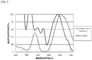
- Fig. 2 shows the excitation spectra in Example 1 and Comparative Example 1.
- Fig. 8 shows the excitation spectra in Comparative Examples 1 to 4.
- the fluorescent materials of Examples 1 to 5 each contain three lanthanoid elements of Tb, Ce and Eu, in which, therefore, a part of the rare earth element Ln constituting the garnet type crystal structure was substituted with the three lanthanoid elements Tb, Ce and Eu, and consequently, these fluorescent materials each gave a strong light emission peak at around a wavelength of 591 nm in the light emission spectrum thereof, as a result of receiving the light from the excitation light source, and therefore had a high relative light emission intensity.
- the fluorescent materials of Examples 1 to 5 each provided an emission color of such that the chromaticity x, y in a CIE1931 chromaticity coordinate system each fall within a range of 0.450 ⁇ x ⁇ 0.580 and 0.410 ⁇ y ⁇ 0.530, as a result of receiving the light from an excitation light source.
- the fluorescent materials of Examples 1 to 3 each provided an emission color having a strong red component.
- the fluorescent materials of Example 4 and Example 5 provided an emission color of orange having a strong yellowing tone.
- x in a CIE1931 chromaticity coordinate system was 0.463 and y was 0.522, that is, the fluorescent material emitted a yellow color.
- the relative light emission intensity at a wavelength of 538 nm was 12% and was extremely low, and the fluorescent material emitted a yellow color light.
- the fluorescent material of Comparative Example 3 barely emitted light, and the relative light emission intensity and the chromaticity thereof could not be measured.
- the relative light emission intensity at a wavelength of 543 nm was 76% and was low, and the fluorescent material emitted a yellowish green to yellow color light.
- the fluorescent material of Example 1 gave a sharp and strong light emission peak at around a wavelength of 591 nm in the light emission spectrum.
- the fluorescent material of Comparative Example 1 had a peak top at around a wavelength of 562 nm, and gave a broad light emission peak in a range of 480 nm or more and 750 nm or less.
- the fluorescent material of Example 1 had a relative intensity of 80% or more in a wavelength range of 400 nm or more and 480 nm or less, more specifically 420 nm or more and 460 nm or less, and efficiently absorbed the light from the excitation light source having a light emission peak wavelength of 380 nm or more and 485 nm or less, and was thereby excited to give a high light emission intensity.
- the fluorescent material of Example 1 had a relative intensity of 80% or more in a wavelength range of 400 nm or more and 480 nm or less, more specifically 420 nm or more and 460 nm or less, and efficiently absorbed the light from the excitation light source having a light emission peak wavelength of 380 nm or more and 485 nm or less, and was thereby excited to give a high light emission intensity.
- Comparative Example 2 also the fluorescent material of Comparative Example 1 had a relative intensity of 80% or more in a wavelength region of 400 nm or more and 480 nm or less, more specifically 430 nm or more and 480 nm or less, and absorbed the light from the excitation light source having a light emission peak wavelength of 380 nm or more and 485 nm or less.
- Garnet-structured fluorescent materials each having a composition of a rare earth aluminum-gallate were obtained in the same manner as in Example 1, except for using Y 2 O 3 , Tb 4 O 7 , CeO 2 , Eu 2 O 3 , Al 2 O 3 , and Ga 2 O 3 as raw materials and weighing the raw materials such that the parameter a, the parameter b, the parameter c and the parameter d had the values shown in Table 2.
- the values of the parameter b and the parameter c in Table 2 are values calculated by multiplying the numerical values in Table 2 by 10 -2 .
- the light mission spectra of the fluorescent materials of Examples 6 to 10 and Comparative Example 5 and the relative light emission intensity (%) at a peak wavelength of 591 nm thereof were determined.
- Example 2 The results in Example 2, Examples 6 to 10 and Comparative Example 5 are shown in Table 2.
- Fig. 3 is a graph showing a relative light emission intensity (%) at a wavelength of 591 nm of each fluorescent material relative to the parameter a in the composition of each fluorescent material.
- Table 2 Tb Ce Eu Ga Peak Wavelength 591 nm Parameter a Parameter b ( ⁇ 10 -2 ) Parameter c ( ⁇ 10 -2 ) Parameter d Relative Light Emission Intensity (%) Comparative Example 5 0.120 0.200 0.200 0.450 48
- Example 7 0.418 161 Example 8 0.528 213
- Example 9 0.647 247
- Example 10 0.996 131
- Garnet-structured fluorescent materials each having a composition of a rare earth aluminum-gallate were obtained in the same manner as in Example 1, except for using Y 2 O 3 , Tb 4 O 7 , CeO 2 , Eu 2 O 3 , Al 2 O 3 , and Ga 2 O 3 as raw materials and weighing the raw materials such that the parameter a, the parameter b, the parameter c and the parameter d had the values shown in Table 3.
- the values of the parameter b and the parameter c in Table 3 are values calculated by multiplying the numerical values in Table 3 by 10 -2 .
- Example 2 In the same manner as in Example 1, the light mission spectra of the fluorescent materials of Examples 11 to 18 and Comparative Examples 6 to 8 and the relative light emission intensity (%) at a peak wavelength of 591 nm thereof were determined.
- Fig. 4 is a graph showing a relative light emission intensity (%) at a wavelength of 591 nm of each fluorescent material relative to the parameter b in the composition of each fluorescent material.
- the light emission intensity of the fluorescent material at around a wavelength of 591 nm was high when the parameter b was 0.008 ⁇ 10 -2 or more and 1.5 ⁇ 10 -2 or less, preferably 0.01 ⁇ 10 -2 or more and 0.95 ⁇ 10 -2 or less, more preferably 0.015 ⁇ 10 -2 or more and 0.7 ⁇ 10 -2 or less.
- Garnet-structured fluorescent materials each having a composition of a rare earth aluminum-gallate were obtained in the same manner as in Example 1, except for using Y 2 O 3 , Tb 4 O 7 , CeO 2 , Eu 2 O 3 , Al 2 O 3 , and Ga 2 O 3 as raw materials and weighing the raw materials such that the parameter a, the parameter b, the parameter c and the parameter d had the values shown in Table 4.
- the values of the parameter b and the parameter c in Table 4 are values calculated by multiplying the numerical values in Table 4 by 10 -2 .
- Example 2 In the same manner as in Example 1, the light mission spectra of the fluorescent materials of Examples 19 to 25 and Comparative Examples 9 to 10 and the relative light emission intensity (%) at a peak wavelength of 591 nm thereof were determined.
- Fig. 5 is a graph showing a relative light emission intensity (%) at a wavelength of 591 nm of each fluorescent material relative to the parameter c in the composition of each fluorescent material.
- the light emission intensity of the fluorescent material at around a wavelength of 591 nm was high when the parameter c was 0.012 ⁇ 10 -2 or more and 2 ⁇ 10 -2 or less, preferably 0.014 ⁇ 10 -2 or more and 1.6 ⁇ 10 -2 or less, more preferably 0.02 ⁇ 10 -2 or more and 1.2 ⁇ 10 -2 or less.
- Garnet-structured fluorescent materials each having a composition of a rare earth aluminum-gallate were obtained in the same manner as in Example 1, except for using Y 2 O 3 , Tb 4 O 7 , CeO 2 , Eu 2 O 3 , Al 2 O 3 , and Ga 2 O 3 as raw materials and weighing the raw materials such that the parameter a, the parameter b, the parameter c and the parameter d had the values shown in Table 5.
- the values of the parameter b and the parameter c in Table 5 are values calculated by multiplying the numerical values in Table 5 by 10 -2 .
- the light mission spectra of the fluorescent materials of Examples 26 to 32 and Comparative Example 11 and the relative light emission intensity (%) at a peak wavelength of 591 nm thereof were determined.
- Example 5 The results in Example 5, Examples 26 to 32 and Comparative Example 11 are shown in Table 5.
- Fig. 6 is a graph showing a relative light emission intensity (%) at a wavelength of 591 nm of each fluorescent material relative to the parameter d in the composition of each fluorescent material.
- Table 5 Tb Ce Eu Ga Peak Wavelength 591 nm Parameter a Parameter b ( ⁇ 10 -2 ) Parameter c ( ⁇ 10 -2 ) Parameter d Relative Light Emission Intensity (%)
- Example 26 0.764 0.600 0.200 0.000 102
- Example 27 0.150
- Example 5 0.200 110 Example 28 0.350 134
- Example 30 0.450 151
- Example 32 0.800 100 Comparative Example 11 1.000 40
- the relative light emission intensity at a wavelength of 538 nm of the fluorescent material of Comparative Example 2 was 12% and was extremely low, and the light emission peak was a broad peak in a broad wavelength range of 500 nm or more and 650 nm or less.
- the fluorescent material of Comparative Example 3 gave an extremely low peak at around a wavelength of 591 nm, the relative light emission intensity thereof was less than 5%, that is, the fluorescent material barely emitted light.
- the fluorescent material of Comparative Example 4 had a composition of a rare earth aluminum-gallate, in which, based on the total molar ratio of Al and Ga of 5, the total molar ratio of the rare earth element Ln, and Tb and Ce and Eu was 3 and the molar ratio of Tb was a product of 3 and the parameter a, but in which the parameter a was less than 0.25. Therefore, the peak wavelength of the fluorescent material, at which the light emission intensity thereof is the highest in a wavelength range of 450 nm to 650 nm, was 543 nm and the relative light emission intensity at a peak wavelength of 543 nm thereof was 76%, that is, the light emission intensity of the fluorescent material is lower than that of the fluorescent materials of Examples 1 to 5.
- the fluorescent materials of Comparative Examples 1 to 4 all had a relative light emission intensity of 80% or more in a wavelength range of 400 nm or more and 480 nm or less, and efficiently absorbed the light from an excitation light source having a light emission peak wavelength of 380 nm or more and 485 nm or less, but these fluorescent materials had a low relative light emission intensity as shown in Fig. 7 .
- a fluorescent material having a composition of a rare earth aluminum-gallate having a high light emission intensity
- a light emitting device using the fluorescent material can be used in lighting systems and sensor systems in security systems.
Landscapes
- Chemical & Material Sciences (AREA)
- Engineering & Computer Science (AREA)
- Inorganic Chemistry (AREA)
- Materials Engineering (AREA)
- Organic Chemistry (AREA)
- Microelectronics & Electronic Packaging (AREA)
- Manufacturing & Machinery (AREA)
- Computer Hardware Design (AREA)
- Power Engineering (AREA)
- Luminescent Compositions (AREA)
- Led Device Packages (AREA)
Abstract
Description
- This application claims priority to Japanese Patent Application No.
2017-100133, filed on May 19, 2017 - The present disclosure relates to a fluorescent material having a composition of a rare earth aluminum-gallate, and a light emitting device using the same. In this specification, the "fluorescent material" is used in the same meaning as a "fluorescent phosphor". Fluorescence refers to the emission of light by a substance that has absorbed light or other electromagnetic radiation. The light can e.g. be UV-radiation or visible light. Typically, the emitted electromagnetic radiation has a longer wavelength than the absorbed electromagnetic radiation.
- A variety of light emitting devices including a light source, such as a light emitting diode (LED) chip, in combination with a fluorescent material have been developed. For example, a light emitting device emitting a white color through a combination of an LED chip emitting blue light with a fluorescent material emitting yellow light has been developed. As a fluorescent material that emits yellow light when excited by receiving blue light from an LED chip, a rare earth aluminate fluorescent material activated by cerium having a garnet structure, for example, Y3Al5O12:Ce (YAG: yttrium aluminium garnet) is known.
- White emission from a combination of an LED chip to emit blue light and a YAG fluorescent material represented by Y3Al5O12:Ce that emits yellow light by receiving blue light is weak in red color emission. For compensating red color emission, a light emitting device combined with a red color-emitting fluorescent material represented by CaAlSiN3:Eu, K2SiF6:Mn, or 3.5MgO·0.5MgF2·GeO2:Mn is also known.
- For compensating a red component which a YAG fluorescent material represented by Y3Al5O12:Ce is poor in, for example, in Japanese Unexamined Patent Publication No.
2002-363555 2006-233158 2007-126670 - However, as the case may be, some fluorescent materials having a composition of a rare earth aluminum-gallate disclosed in Japanese Unexamined Patent Publication No.
2002-363555 2006-233158 2007-126670 - An object of the present disclosure is to provide a fluorescent material having a composition of a rare earth aluminum-gallate in which a red component has been reinforced and which has a high emission intensity, and to provide a light emitting device using the fluorescent material. The term "rare earth aluminum-gallate" is used to denote fluorescent materials containing one or more rare earth metals and aluminum which may, or may not contain gallium.
- For solving the above-mentioned problems, the present disclosure includes the following embodiments.
- A first embodiment of the present disclosure relate to a fluorescent material having a composition of a rare earth aluminum-gallate, which contains at least one rare earth element Ln selected from the group consisting of Y, Gd, La, Lu, Sc and Sm; at least one Group 13 element selected from Al and Ga; Tb; Ce; and Eu, and wherein when a total molar ratio 5 of Al and Ga is used as a basis, the total molar ratio of Ln, and Tb, Ce and Eu is 3, the molar ratio of Tb is a product of 3 and a value of a parameter a, the molar ratio of Ce is a product of 3 and a value of a parameter b, the molar ratio of Eu is a product of 3 and a value of a parameter c, the molar ratio of Ga is a product of 5 and a value of a parameter d, the parameter a is 0.25 or more and less than 1, the parameter b is 0.008 × 10⁻² or more and 1.5 × 10⁻² or less, the parameter c is 0.012 × 10⁻² or more and 2 × 10⁻² or less, and the parameter d is 0 or more and 0.85 or less. The term 'molar ratio' as used in the present invention refers to the molar amount of an element in one mole of the chemical composition of the fluorescent material.
- A second aspect of the present invention is a light emitting device containing the fluorescent material and an excitation light source.
- According to the embodiments of the present disclosure, there can be provided a fluorescent material having a composition of a rare earth aluminum-gallate in which a red component has been reinforced and which has a high light emission intensity, and a light emitting device using the fluorescent material.
-
-
Fig. 1 is a diagram showing a light emission spectrum of the fluorescent material of Example 1 and a light emission spectrum of the fluorescent material of Comparative Example 1. -
Fig. 2 is a diagram showing an excitation spectrum of the fluorescent material of Example 1 and an excitation spectrum of the fluorescent material of Comparative Example 1. -
Fig. 3 is a graph showing a relative light emission intensity (%) at a wavelength of 591 nm of each fluorescent material relative to the amount of Tb (a value of a parameter a) contained in each of the fluorescent materials of Example 2, Examples 6 to 10 and the fluorescent material of Comparative Example 5. -
Fig. 4 is a graph showing a relative light emission intensity (%) at a wavelength of 591 nm of each fluorescent material relative to the amount of Ce (a value of a parameter b) contained in each of the fluorescent materials of Example 2, Examples 11 to 18 and the fluorescent materials of Comparative Examples 6 to 8. -
Fig. 5 is a graph showing a relative light emission intensity (%) at a wavelength of 591 nm of each fluorescent material relative to the amount of Eu (a value of a parameter c) contained in each of the fluorescent materials of Example 2, Examples 19 to 25 and the fluorescent materials of Comparative Examples 9 to 10. -
Fig. 6 is a graph showing a relative light emission intensity (%) at a wavelength of 591 nm of each fluorescent material relative to the amount of Ga (a value of a parameter d) contained in each of the fluorescent materials of Example 5, Examples 26 to 32 and the fluorescent material of Comparative Example 11. -
Fig. 7 is a diagram showing light emission spectra of the fluorescent materials of Comparative Examples 1 to 4. -
Fig. 8 is a diagram showing excitation spectra of the fluorescent materials of Comparative Examples 1 to 4. - The fluorescent material and the light emitting device according to the present invention are described hereunder on the basis of embodiments. The embodiments as shown below are exemplifications for exemplifying the technical concept of the present invention, and the present invention is not limited to the fluorescent materials and the light emitting devices shown below. The relationship between the color name and the chromaticity coordinate, the relationship between the wavelength range of light and the color name of monochromic light are in accordance with JIS Z8110 and can be determined as set out in the experimental examples.
- The first embodiment of the present disclosure is a fluorescent material having a composition of a rare earth aluminum-gallate, which contains at least one rare earth element Ln selected from the group consisting of Y, Gd, La, Lu, Sc and Sm; at least one Group 13 element selected from Al and Ga; Tb; Ce; and Eu. When a total molar ratio 5 of Al and Ga is used as a basis, a total molar ratio of Ln, and Tb, Ce and Eu is 3, a molar ratio of Tb is a product of 3 and a value of a parameter a, a molar ratio of Ce is a product of 3 and a value of a parameter b, a molar ratio of Eu is a product of 3 and a value of a parameter c, a molar ratio of Ga is a product of 5 and a value of a parameter d. The parameter a is 0.25 or more and less than 1. The parameter b is 0.008 × 10⁻² or more and 1.5 × 10⁻² or less. The parameter c is 0.012 × 10⁻² or more and 2 × 10⁻² or less. The parameter d is 0 or more and 0.85 or less.
- The fluorescent material of the first embodiment contains, as essential elements, at least one rare earth element Ln selected from the group consisting of Y, Gd, La, Lu, Sc and Sm; at least one Group 13 element selected from aluminum (Al) and gallium (Ga); and in addition to oxygen (O), three kinds of elements of terbium (Tb), cerium (Ce) and europium (Eu), which form part of a crystal structure of a rare earth aluminum-gallate. The total molar ratio of oxygen (O) is preferably 12. The fluorescent material having the composition of a rare earth aluminum-gallate contains three kinds of lanthanoid elements Tb, Ce and Eu each in a predetermined amount, in which, therefore, a part of the rare earth elements constituting a garnet-type crystal structure are substituted with three elements of Tb, Ce and Eu to reinforce a red color component, and accordingly, the material provides light emission when excited with light from an excitation light source. In the light emission spectrum of the material, a sharp and strong light emission peak appears at around a wavelength of 591 nm, and thus the material has a high light emission intensity. The rare earth element Ln to be comprised in the composition of the rare earth aluminum-gallate of the fluorescent material is preferably at least one selected from the group consisting of Y, Gd, La, Lu and Sc.
- The fluorescent material having a composition of a rare earth aluminum-gallate preferably has a composition represented by the following formula (I):
(Ln1-a-b-cTbaCebEuc)3(Al1-dGad)5O12 (I)
wherein Ln represents at least one rare earth element selected from the group consisting of Y, Gd, La, Lu, Sc and Sm, and the values of parameters a, b, c and d are numbers satisfying 0.25 ≤ a < 1, 0.008 × 10⁻² ≤ b ≤ 1.5 × 10⁻², 0.012 × 10⁻² ≤ c ≤ 2 × 10⁻², and 0 ≤ d ≤ 0.85, respectively. - In the composition of a rare earth aluminum-gallate for the fluorescent material, when the total molar ratio 5 of Al and Ga is used as a basis, the total molar ratio of the rare earth element Ln, and Tb, Ce and Eu is 3, and the molar ratio of Tb is a product of 3 and a value of a parameter a, the parameter a indicating the amount of Tb is 0.25 or more and less than 1, preferably 0.3 or more and less than 1, more preferably 0.35 or more and less than 1, even more preferably 0.35 or more and 0.9998 or less. In the composition of a rare earth aluminium gallate, when the parameter a is less than 0.25, the light emission intensity at around a wavelength of 591 nm is low.
- In the fluorescent material, Tb functions as one light emission center. In the composition of a rare earth aluminum-gallate, the parameter a indicating the amount of Tb is 0.25 or more and less than 1, and therefore owing to energy transfer from Ce to Tb, a sharp and strong light emission peak appears at around a wavelength of 591 nm in the light emission spectrum. On the other hand, in the light emission spectrum of a YAG fluorescent material having Ce as a single activator or a YAG fluorescent material having two activators of Ce and Eu, a broad peak appears, having a light emission peak in a wavelength region for light emission in yellowish green to yellow.
- In the composition of a rare earth aluminum-gallate for the fluorescent material, when the total molar ratio 5 of Al and Ga is used as a basis, the total molar ratio of the rare earth element Ln, and Tb, Ce and Eu is 3, and the molar ratio of Ce is a product of 3 and a value of a parameter b, the parameter b indicating the amount of Ce is 0.008 × 10⁻² or more and 1.5 × 10⁻² or less, preferably 0.01 × 10⁻² or more and 0.95 × 10⁻² or less, more preferably 0.015 × 10⁻² or more and 0.7 × 10⁻² or less. In the composition of a rare earth aluminium gallate, when the parameter b is less than 0.008 × 10⁻² or more than 1.5 × 10⁻², the light emission intensity at around a wavelength of 591 nm is low.
- In the fluorescent material, Ce functions as one light emission center. In the composition of a rare earth aluminum-gallate for the fluorescent material, when the parameter b indicating the amount of Ce is 0.008 × 10⁻² or more and 1.5 × 10⁻² or less and when the composition contains two elements Tb and Eu in addition to Ce, a sharp and strong light emission peak can appear at around a wavelength of 591 nm from a broad peak having a peak top at around a wavelength of 550 nm of a fluorescent material having Ce as a single activator, in the light emission spectrum.
- In the composition of a rare earth aluminum-gallate for the fluorescent material, when the total molar ratio 5 of Al and Ga is used as a basis, the total molar ratio of the rare earth element Ln, and Tb, Ce and Eu is 3, and the molar ratio of Eu is a product of 3 and a value of a parameter c, the parameter c indicating the amount of Eu is 0.012 × 10⁻² or more and 2 × 10⁻² or less, preferably 0.014 × 10⁻² or more and 1.6 × 10⁻² or less, more preferably 0.02 × 10⁻² or more and 1.2 × 10⁻² or less. In the composition of a rare earth aluminum-gallate, when the parameter c is less than 0.012 × 10⁻² or more than 2 × 10⁻², the light emission intensity at around a wavelength of 591 nm is low.
- In the composition of a rare earth aluminum-gallate, Eu functions as one light emission center. In the composition of a rare earth aluminum-gallate for the fluorescent material, when the parameter c indicating the amount of Eu is 0.012 × 10⁻² or more and 2 × 10⁻² or less and when the composition contains Tb and Eu in addition to Ce, a sharp and strong light emission peak can appear in the light emission spectrum at around a wavelength of 591 nm as opposed to a broad peak having a peak top at around a wavelength of 550 nm of a fluorescent material having Ce as a single activator, owing to energy transfer from Ce to Eu and Tb.
- For the fluorescent material of the first embodiment of the present disclosure, preferably, the composition of a rare earth aluminum-gallate contains Ga. In general, it is known that, in a YAG fluorescent material having a garnet structure, Ga is substituted with a site of Al in the crystal structure, and therefore the crystal structure becomes unstable and the light emission intensity lowers. Contrary to this general knowledge, the present inventors have found that when the composition of a rare earth aluminum-gallate for a fluorescent material contains Ga, the light emission intensity at around a wavelength of 591 nm becomes higher in the light emission spectrum. In the composition of a rare earth aluminum-gallate for the fluorescent material, the parameter d indicating the amount of Ga is 0 or more and 0.85 or less, preferably 0.1 or more and 0.8 or less, more preferably 0.15 or more and 0.75 or less. In the composition of a rare earth aluminum-gallate for the fluorescent material, when the parameter d indicating the amount of Ga is 0.85 or less, the light emission intensity at around 591 nm can be higher in the light emission spectrum.
- In a CIE1931 chromaticity coordinate system, the chromaticity of the emission color from the fluorescent material of the first embodiment of the present disclosure preferably falls within a range of 0.420 ≤ x ≤ 0.600, and 0.300 ≤ y ≤ 0.530, more preferably within a range of 0.450 ≤ x ≤ 0.590, and 0.350 ≤ y ≤ 0.525, even more preferably within a range of 0.480 ≤ x ≤ 0.580, and 0.400 ≤ y ≤ 0.520. In a CIE1931 chromaticity coordinate system, when the chromaticity x, y of the emission color from the fluorescent material falls within the above-mentioned range, the red component in the fluorescent material is reinforced and therefore the material provides light emission from a reddish orange color to a yellowing orange color. The emission color that the fluorescent material of an embodiment of the present disclosure gives as a result of photoexcitation in a region of near-ultraviolet to blue color, specifically as a result of absorption of light falling within a wavelength range of 380 nm or more and 485 nm or less, preferably falls within the above-mentioned range of x, y in a CIE1931 chromaticity coordinate system.
- As a method for producing the fluorescent material having a composition of a rare earth aluminum-gallate, the following method is exemplified.
- In the method, respective raw materials including one or more compound containing at least one rare earth element Ln selected from the group consisting of Y, Gd, La, Lu, Sc and Sm, one or more compound containing at least one Group 13 element selected from Al and Ga, one or more compound containing Tb, one or more compound containing Ce and one or more compound containing Eu are mixed such that, when the total molar ratio 5 of Al and Ga is used as a basis, the total molar ratio of Ln, and Tb, Ce and Eu is 3, the molar ratio of Tb is a product of 3 and the value of the parameter a, the molar ratio of Ce is a product of 3 and the value of the parameter b, the molar ratio of Eu is the product of 3 and the value of the parameter c, the molar ratio of Ga is the product of 5 and the value of a parameter d, the parameter a is 0.25 or more and less than 1, preferably the parameter a is 0.25 or more and 0.9998 or less, the parameter b is 0.008 × 10⁻² or more and 1.5 × 10⁻² or less, the parameter c is 0.012 × 10⁻² or more and 2 × 10⁻² or less, and the parameter d is 0 or more and 0.85 or less, to give a raw material mixture, and this raw material mixture is heat-treated to give a fluorescent material having a composition of a rare earth aluminum-gallate.
- Examples of the compound containing a rare earth element include an oxide, a hydroxide, a nitride, an oxynitride, a fluoride, and a chloride, each containing at least one rare earth element Ln selected from the group consisting of Y, Gd, La, Lu, Sc and Sm. Such a compound may be a hydrate. Among the compounds containing a rare earth element Ln, an unalloyed metal or an alloy containing a rare earth element may also be used as at least a part thereof.
- Specifically, examples of the compound containing a rare earth element include Y2O3, Y(OH)3, YN, YF3, YCl3, Gd2O3, Gd(OH)3, GdN, GdF3, GdCl3, Lu2O3, LuF3, LuCl3, La2O3, La(OH)3, LaF3, LaCl3, Sc2O3, ScN, ScF3, ScCl3, Sm2O3, SmN, SmF3, SmCl3, etc. The compound containing a rare earth element may be used alone, or may be used in combination of two or more thereof. The compound containing a rare earth element is preferably an oxide. This is because, when compared to other materials, the oxide does not contain any other element than the desired composition of a rare earth aluminum-gallate.
- Examples of the compound containing at least one Group 13 element selected from Al and Ga include an oxide, a hydroxide, a nitride, an oxynitride, a fluoride and a chloride each containing aluminum or gallium. Such a compound may be a hydrate. As the compound containing aluminum or gallium, an aluminum metal simple substance, a gallium metal simple substance, an aluminum alloy, or a gallium alloy may be used, and the metal simple substance or alloy may also be used in place of at least a part of the compound.
- Specifically, example of the compound containing at least one Group 13 element selected from Al and Ga include aluminum oxynitride, Al2O3, Al(OH)3, AlN, AlF3, AlCl3, Ga2O3, Ga(OH)3, GaN, GaF3, and GaCl3. The compound containing at least one Group 13 element selected from Al or Ga may be used alone, or may be used in combination of two or more thereof. The compound containing at least one Group 13 element selected from Al and Ga is preferably an oxide. The reason for this resides in the matter that, when compared to other materials, the oxide does not contain any other element than the desired composition of a rare earth aluminum-gallate, and the fluorescent material having a desired composition is readily obtainable. In addition, in the case of using a compound containing any other element than the desired composition, there is a case where a residual impurity element may be existent in the resulting fluorescent material, and there is a concern that this residual impurity element becomes a killer element with respect to light emission, resulting in a remarkable lowering of the light emission intensity.
- Examples of the compound containing Tb include an oxide, a fluoride and a chloride containing terbium. Such a compound may be a hydrate. As the compound containing terbium, a terbium metal simple substance or a terbium alloy may be used, and the metal simple substance or alloy may also be used in place of at least a part of the compound.
- Specifically, examples of the compound containing Tb include Tb4O7, TbF3, and TbCl3. The compound containing Tb may be used alone, or may be used in combination of two or more thereof. The compound containing Tb is preferably an oxide. The reason for this resides in the matter that, when compared to other materials, the oxide does not contain any other element than the desired composition of a rare earth aluminum-gallate, and the fluorescent material having a desired composition is readily obtainable. In addition, in the case of using a compound containing any other element than the desired composition, there is a case where a residual impurity element may be existent in the resulting fluorescent material, and there is a concern that this residual impurity element becomes a killer with respect to light emission, resulting in a remarkable lowering of the light emission intensity.
- Examples of the compound containing Ce include an oxide, a hydroxide, a nitride, a fluoride, and a chloride, each containing cerium. Such a compound may be a hydrate. As the compound containing cerium, a cerium metal simple substance or a cerium alloy may be used, and the metal simple substance or alloy may also be used in place of at least a part of the compound.
- Specifically, examples of the compound containing Ce include CeO2, Ce(OH)2, Ce(OH)4, CeN, CeF3, and CeCl3. The compound containing Ce may be used alone, or may be used in combination of two or more thereof. The compound containing Ce is preferably an oxide. The reason for this resides in the matter that, when compared to other materials, the oxide does not contain any other element than the desired composition of a rare earth aluminum-gallate, and the fluorescent material having a desired composition is readily obtainable. In addition, in the case of using a compound containing any other element than the desired composition, there is a case where a residual impurity element may be existent in the resulting fluorescent material, and there is a concern that this residual impurity element becomes a killer with respect to light emission, resulting in a remarkable lowering of the light emission intensity.
- Examples of the compound containing Eu include an oxide, a fluoride, and a chloride, each containing europium. Such a compound may be a hydrate. As the compound containing europium, an europium metal simple substance or an europium alloy may be used, and the metal simple substance or alloy may also be used in place of at least a part of the compound.
- Specifically, examples of the compound containing Eu include Eu2O3, EuF3, and EuCl3. The compound containing Eu may be used alone, or may be used in combination of two or more thereof. The compound containing Eu is preferably an oxide. The reason for this resides in the matter that, when compared to other materials, the oxide does not contain any other element than the desired composition of a rare earth aluminum-gallate, and the fluorescent material having a desired composition is readily obtainable. In addition, in the case of using a compound containing any other element than the desired composition, there is a case where a residual impurity element may be existent in the resulting fluorescent material, and there is a concern that this residual impurity element becomes a killer with respect to light emission, resulting in a remarkable lowering of the light emission intensity.
- The raw material mixture may contain a flux, such as a halide or the like, as the need arises. When a flux is contained in the raw material mixture, the reaction between the raw materials is promoted, and a solid phase reaction is easy to advance more uniformly. As for this matter, it may be considered that the temperature at which the raw material mixture is heat-treated is substantially the same as or higher than the formation temperature of a liquid phase of a halide or the like to be used as the flux, so that the reaction could be promoted.
- Examples of the halide include fluorides, chlorides of a rare earth metal, an alkaline earth metal, or an alkali metal. In the case where a halide of a rare earth metal is used as a flux, the flux can also be added as the compound such that the product has a desired composition of a rare earth aluminum-gallate. In other words, if rare earth metal containing flux components are used, their amount is taken into account in the calculation of the final composition of the fluorescent material. Specifically, examples of the flux include barium fluoride (BaF2), calcium fluoride (CaF2), etc. The flux is preferably barium fluoride (BaF2). This is because by using barium fluoride as the flux, the garnet crystal structure becomes stable, and a composition of the garnet crystal structure is readily formed.
- In the case where the raw material mixture contains a flux, the content of the flux is preferably 20% by mass or less, more preferably 10% by mass or less, and preferably 0.1% by mass or more, on the basis of the raw material mixture (100% by mass). This is because when the content of the flux falls within the aforementioned range, the matter that the garnet crystal structure is hardly formed due to insufficient particle growth because of a small amount of the flux does not occur, and the matter that the garnet crystal structure is hardly formed because of an excessive amount of the flux does not also occur.
- As for the raw material mixture, after weighing the respective raw materials in a desired blending ratio, for example, the raw materials may be ground and mixed using a dry grinder, such as a ball mill, a vibration mill, a hammer mill, a roll mill, a jet mill, etc.; may be ground and mixed using a mortar and a pestle, etc.; may be mixed using a mixing machine, for example, a ribbon blender, a Henschel mixer, a V type blender, etc.; or may be ground and mixed using both a dry grinder and a mixing machine. In addition, the mixing may be achieved by means of either dry mixing or wet mixing with addition of a solvent, etc. The mixing is preferably dry mixing. This is because, when compared to the wet mode, the dry mode enables the process time to be shortened, leading to an improvement in productivity.
- The raw material mixture can be heat-treated by charging in a crucible, a boat made of, as a material, a carbon material, such as graphite etc., or boron nitride (BN), aluminum oxide (alumina), tungsten (W), or molybdenum (Mo).
- From the viewpoint of stability of the crystal structure, the temperature at which the raw material mixture is heat-treated is preferably in a range of 800°C or higher and 1800°C or lower, more preferably 900°C or higher and 1750°C or lower, even more preferably 1000°C or higher and 1700°C or lower, and especially preferably 1100°C or higher and 1650°C or lower.
- The heat treatment time varies depending upon a temperature elevation rate, a heat treatment atmosphere, and so on, and after reaching the heat treatment temperature, the heat treatment time is preferably 1 hour or more, more preferably 2 hours or more, and even more preferably 3 hours or more, and preferably 20 hours or less, more preferably 18 hours or less, and even more preferably 15 hours or less.
- As for the atmosphere where the raw material mixture is heat-treated, the heat treatment can be performed in an inert atmosphere of argon, nitrogen, or a reducing atmosphere containing hydrogen, etc., or an oxidizing atmosphere in the air, etc. It is preferred that the raw material mixture is heat-treated in a nitrogen atmosphere having reducing properties to give the fluorescent material. The atmosphere where the raw material mixture is heat-treated is more preferably a hydrogen gas-containing nitrogen atmosphere.
- For the fluorescent material having a composition of a rare earth aluminum-gallate, the reactivity of the raw material mixture becomes good in an atmosphere having a high reducing power, such as a reducing atmosphere containing hydrogen and nitrogen, and can be heat-treated at atmospheric pressure without being pressurized. For the heat treatment, for example, an electric furnace, a gas furnace, and so on can be used.
- The resulting fluorescent material may be wet dispersed and subjected to a post-treatment step, such as wet sieving, dehydration, drying, dry sieving, etc. According to such a post-treatment step, the fluorescent material having a desired average particle diameter is obtained. For example, the fluorescent material after the heat treatment is dispersed in a non-aqueous organic solvent or an aqueous solvent; a solvent flow is allowed to flow onto the dispersed fluorescent material on a sieve while applying a variety of vibrations via the sieve, thereby subjecting the calcined product to mesh passing to achieve wet sieving; and subsequently, dehydration, drying, and dry sieving are performed. There can be thus obtained the fluorescent material having a desired average particle diameter.
- By dispersing the fluorescent material after the heat treatment in an aqueous medium, impurities, such as a calcination residue of the flux and unreacted components of the raw materials can be removed. For the wet dispersion, a dispersion medium, such as alumina balls, zirconia balls, etc. may be used.
- Next, a light emitting device utilizing the resulting fluorescent material as a constituent element of a wavelength conversion member is explained. The light emitting device of the second embodiment of the present disclosure includes at least fluorescent material of the first embodiment of the disclosure and an excitation light source.
- For the excitation light source, a light emitting element can be used. The light emitting element is preferably one having a light emission peak wavelength in a wavelength range of 250 nm or more and 500 nm or less. The range of the light emission peak wavelength of the light emitting element is more preferably in a wavelength range of 350 nm or more and 490 nm or less, and even more preferably 380 nm or more and 485 nm or less, still more preferably 400 nm or more and 480 nm or less. By using such a light emitting element as the excitation light source, there can be provided a light emitting device having a combination of the fluorescent material of the first aspect of the invention that has a sharp and strong emission peak at around a wavelength of 591 nm in the light emission spectrum, and the excitation light source.
- The full width at half maximum of the light emission spectrum of the light emitting element can be, for example, controlled to 30 nm or less. The full width at half maximum means the wavelength width of the emission peak showing the emission intensity of 50% of the maximum emission intensity in the light emission spectrum of the light emitting element.
- For the light emitting element, a semiconductor light emitting element using a nitride-based semiconductor (InxAlYGa1-X-YN, 0 ≤ X, 0 ≤ Y, X+Y ≤1) is preferably used. By using a semiconductor light emitting element as the light source, a stable light emitting device which is high in efficiency, high in linearity of an output to an input, and strong against mechanical impact can be provided.
- The fluorescent material which is included in the light emitting device is preferably a fluorescent material having the composition represented by the aforementioned formula (I). The fluorescent material which is included in the light emitting device is excited with light in a wavelength range of 250 nm or more and 500 nm or less. The light emitting device may be comprised of, as a first fluorescent material, the aforementioned fluorescent material of the first embodiment of the disclosure, and may include, in addition to this first fluorescent material, a second fluorescent material, and a combination of plurality of fluorescent materials may be used as the second fluorescent material.
- The fluorescent material of the first embodiment of the disclosure may be contained, for example, in a fluorescent member that covers an excitation light source, and may form part of the light emitting device. In the light emitting device, the excitation light source is covered with the fluorescent member containing the fluorescent material of the first embodiment of the disclosure, and a part of light emitted by the excitation light source is absorbed by the fluorescent material of the first embodiment of the disclosure, and consequently, light having a sharp and strong emission peak at around a wavelength of 591 nm is thereby emitted.
- It is preferred that the light emitting device contains the second fluorescent material which is different in the light emission peak wavelength from the first fluorescent material. For example, when the light emitting device suitably includes the light emitting element, the first fluorescent material which is excited with this and has a sharp light emission peak having a high light emission intensity at around a wavelength of 591 nm, and the second fluorescent material which is different in the wavelength region to be emitted, light in a broad wavelength region can be emitted.
- The second fluorescent material may be a fluorescent material capable of absorbing the light from the light emitting element and wavelength-converting it into light having a different wavelength. For example, the second fluorescent material is preferably at least any one or more selected from a nitride-based fluorescent material mainly activated with a lanthanide series element, such as Eu, Ce, etc.; an oxynitride-based fluorescent material; a sialon-based fluorescent material; an alkaline earth halogen apatite fluorescent material mainly activated with a lanthanide series element, such as Eu, etc., or a transition metal series element, such as Mn, etc.; an alkaline earth metal halogen borate fluorescent material; an alkaline earth metal aluminate fluorescent material; an alkaline earth silicate; an alkaline earth sulfide; an alkaline earth thiogallate; an alkaline earth silicon nitride; a germanate; a rare earth aluminate mainly activated with a lanthanide series element, such as Ce, etc.; a rare earth silicate; an organic material and an organic complex mainly activated with a lanthanide series element, such as Eu, etc. By using such a fluorescent material alone or in combination of two or more thereof together with the fluorescent material of the first aspect of the invention, blue, green, yellow, red, and so on, as well as color tints that are neutral colors thereof, such as blue-green, yellow-green, orange and others, can be realized in addition to white color.
- The fluorescent material of the first embodiment of the disclosure can form part of a fluorescent member covering the light emitting element together with the second fluorescent material and a sealing resin, as the need arises. Examples of the resin which forms part of the fluorescent member may include thermosetting resins, such as a silicone resin inclusive of a modified silicone resin, an epoxy resin, etc.
- The fluorescent member may further contain, in addition to the resin and the fluorescent material, a filler, a light diffusing material, and so on. For example, when containing a light diffusing material, the directivity from the light emitting element is mitigated, thereby enabling a viewing angle to be increased. Examples of the filler may include silica, titanium oxide, zinc oxide, zirconium oxide, alumina, etc.
- The light emitting device of the second aspect of the present invention can be used in lighting systems and security systems.
- The fluorescent material of the first embodiment of the disclosure can be used in a light emitting device that emits a red color by laser excitation, in addition to the light emitting device of the second embodiment of the disclosure.
- The present invention is hereunder specifically described by reference to the following Examples and Comparative Examples. The present invention is not limited to these Examples.
- 49.60 g of Y2O3, 274.95 g of Tb4O7, 0.66 g of CeO2, 0.67 g of Eu2O3, 89.66 g of Al2O3, and 134.78 g of Ga2O3 were weighed as raw materials. To the raw materials, 22.00 g of BaF2 was added as a flux. These raw materials were dry mixed for 1 hour with a ball mill to give a raw material mixture. The resulting raw material mixture was filled in an alumina crucible and heat-treated at 1500°C for 10 hours. The heat treatment was performed in a nitrogen atmosphere containing a hydrogen gas having reducing properties. The resulting heat-treated product was passed through a sieve to give a fluorescent material having a composition of (Y0.229Tb0.768Ce0.001Eu0.002)3(Al0.55Ga0.45)5O12.
- A fluorescent material having a composition of (Y0.229Tb0.767Ce0.002Eu0.002)3(Al0.55Ga0.45)5O12. was obtained in the same manner as in Example 1, except for weighing and using 49.57 g of Y2O3, 274.79 g of Tb4O7, 0.66 g of CeO2, 0.67 g of Eu2O3, 89.61 g of Al2O3, and 134.70 g of Ga2O3 as the raw materials.
- A fluorescent material having a composition of (Y0.229Tb0.767Ce0.002Eu0.002)3(Al0.55Ga0.45)5O12 was obtained in the same manner as in Example 1, except for weighing and using 68.78 g of La2O3, 264.24 g of Tb4O7, 0.63 g of CeO2, 0.65 g of Eu2O3, 86.17 g of Al2O3, and 129.53 g of Ga2O3 as the raw materials.
- A fluorescent material having a composition of (Y0.468Tb0.528Ce0.002Eu0.002)3(Al0.55Ga0.45)5O12 was obtained in the same manner as in Example 1, except for weighing and using 105.21 g of Y2O3, 196.45 g of Tb4O7, 0.69 g of CeO2, 0.70 g of Eu2O3, 98.65 g of Al2O3, and 148.30 g of Ga2O3 as the raw materials.
- A fluorescent material having a composition of (Y0.228Tb0.764Ce0.006Eu0.002)3(Al0.8Ga0.2)5O12 was obtained in the same manner as in Example 1, except for weighing and using 52.64 g of Y2O3, 291.76 g of Tb4O7, 2.11 g of CeO2, 0.72 g of Eu2O3, 138.95 g of Al2O3, and 63.82 g of Ga2O3 as the raw materials.
- 230.50 g of Y2O3, 93.92 g of Gd2O3, 5.35 g of CeO2, and 220.23 g of Al2O3 were weighed as raw materials. As a flux, 22.00 g of BaF2 was added to the raw materials. These raw materials were dry mixed for 1 hour with a ball mill to give a raw material mixture. The resulting raw material mixture was filled in an alumina crucible and heat-treated at 1450°C for 10 hours. The heat treatment was performed in a nitrogen atmosphere containing a hydrogen gas having reducing properties. The resulting heat-treated product was made to pass through a sieve to give a fluorescent material having a composition of (Y0.788Gd0.2Ce0.012)3Al5O12.
- A fluorescent material having a composition of (Y0.95Ce0.017Eu0.033)3Al5O12 was obtained in the same manner as in Example 1, except for weighing and using 293.48 g of Y2O3, 8.01 g of CeO2, 15.89 g of Eu2O3, and 232.60 g of Al2O3 as the raw materials.
- A fluorescent material having a composition of (Tb0.92Ce0.01Eu0.07)3Al5O12 was obtained in the same manner as in Example 1, except for weighing and using 349.01 g of Tb4O7, 3.49 g of CeO2, 25.00 g of Eu2O3, and 172.50 g of Al2O3 as the raw materials.
- A fluorescent material having a composition of (Y0.875Tb0.119Ce0.003Eu0.003)3(Al0.6Ga0.4)5O12 was obtained in the same manner as in Example 1, except for weighing and using 227.58 g of Y2O3, 52.06 g of Tb4O7, 1.21 g of CeO2, 1.23 g of Eu2O3, 119.08 g of Al2O3, and 145.85 g of Ga2O3 as the raw materials.
- The fluorescent materials of Examples 1 to 5 and Comparative Examples 1 to 4 were subjected to composition analysis and to measurement of relative light emission intensity and luminescent chromaticity, according to the methods mentioned below.
- Composition analysis was performed according to an alkali fusion method using an ICP emission spectrophotometer (OPTIMA, manufactured by Perkin Elmer, Inc.).
- With respect to the fluorescent materials of the Examples and Comparative Examples, light was applied at an excitation wavelength of 450 nm, and a relative light emission intensity (PL Intensity) (%) to the wavelength was measured at room temperature (25°C ± 5°C) with a spectrofluorophotometer (QE-2000, manufactured by Otsuka Electronics Co., Ltd.). With respect to the fluorescent materials of the Examples and Comparative Examples, the wavelength at which the light emission intensity is the highest in a wavelength region of 450 nm to 650 nm is referred to as the light emission peak wavelength (nm), and the light emission intensity at the light emission peak wavelength in Examples and Comparative Examples was expressed as a relative light emission intensity (%) relative to the light emission intensity at the light emission peak wavelength in Comparative Example 1, 100%. The results are shown in Table 1.
Fig. 1 shows the light emission spectra in Example 1 and Comparative Example 1.Fig. 7 shows the light emission spectra in Comparative Examples 1 to 4. - With respect to the fluorescent materials of the Examples and Comparative Examples, the chromaticity x, y was measured in a CIE1931 chromaticity coordinate system, using a quantum efficiency measuring apparatus (QE-2000, manufactured by Otsuka Electronics Co., Ltd.). The results are shown in Table 1.
- With respect to the fluorescent materials of the Examples and Comparative Examples, the excitation spectrum of each fluorescent material was measured at the light emission peak wavelength thereof, at room temperature (25°C ± 5°C) and in a range of 250 nm or more and 510 nm or less, using a fluorescence spectrophotometer (product name: F-4500, manufactured by Hitachi High-Technologies Corporation). In the excitation spectrum pattern, the maximum intensity of the spectrum of each fluorescent material is referred to as 100%.
Fig. 2 shows the excitation spectra in Example 1 and Comparative Example 1.Fig. 8 shows the excitation spectra in Comparative Examples 1 to 4.Table 1 Fluorescent Material Composition Light Emission Peak Wavelength (nm) Relative Light Emission Intensity (%) Chromaticity x y Example 1 (Y0.229Tb0.768Ce0.001Eu0.002)3(Al0.55Ga0.45)5O12 591 273 0.576 0.419 Example 2 (Y0.229Tb0.767Ce0.002Eu0.002)3(Al0.55Ga0.45)5O12 591 247 0.554 0.438 Example 3 (La0.229Tb0.767Ce0.002Eu0.002)3(Al0.55Ga0.45)5O12 591 236 0.553 0.439 Example 4 (Y0.468Tb0.528Ce0.002Eu0.002)3(Al0.55Ga0.45)5O12 591 213 0.486 0.498 Example 5 (Y0.228Tb0.764Ce0.006Eu0.002)3(Al0.8Ga0.2)5O12 591 110 0.454 0.522 Comparative Example 1 (Y0.788Gd0.2Ce0.012)3Al5O12 562 100 0.463 0.522 Comparative Example 2 (Y0.95Ce0.017Eu0.033)3Al5O12 538 12 0.425 0.556 Comparative Example 3 (Tb0.92Ce0.01Eu0.07)3Al5O12 - - - - Comparative Example 4 (Y0.875Tb0.119Ce0.003Eu0.003)3(Al0.6Ga0.4)5O12 543 76 0.345 0.561 - As shown in Table 1, the fluorescent materials of Examples 1 to 5 each contain three lanthanoid elements of Tb, Ce and Eu, in which, therefore, a part of the rare earth element Ln constituting the garnet type crystal structure was substituted with the three lanthanoid elements Tb, Ce and Eu, and consequently, these fluorescent materials each gave a strong light emission peak at around a wavelength of 591 nm in the light emission spectrum thereof, as a result of receiving the light from the excitation light source, and therefore had a high relative light emission intensity. In addition, the fluorescent materials of Examples 1 to 5 each provided an emission color of such that the chromaticity x, y in a CIE1931 chromaticity coordinate system each fall within a range of 0.450 ≤ x ≤ 0.580 and 0.410 ≤ y ≤ 0.530, as a result of receiving the light from an excitation light source. The fluorescent materials of Examples 1 to 3 each provided an emission color having a strong red component. The fluorescent materials of Example 4 and Example 5 provided an emission color of orange having a strong yellowing tone.
- Regarding the fluorescent material of Comparative Example 1, x in a CIE1931 chromaticity coordinate system was 0.463 and y was 0.522, that is, the fluorescent material emitted a yellow color. Regarding the fluorescent material of Comparative Example 2, the relative light emission intensity at a wavelength of 538 nm was 12% and was extremely low, and the fluorescent material emitted a yellow color light. The fluorescent material of Comparative Example 3 barely emitted light, and the relative light emission intensity and the chromaticity thereof could not be measured. Regarding the fluorescent material of Comparative Example 4, the relative light emission intensity at a wavelength of 543 nm was 76% and was low, and the fluorescent material emitted a yellowish green to yellow color light.
- As shown in
Fig. 1 , the fluorescent material of Example 1 gave a sharp and strong light emission peak at around a wavelength of 591 nm in the light emission spectrum. On the other hand, the fluorescent material of Comparative Example 1 had a peak top at around a wavelength of 562 nm, and gave a broad light emission peak in a range of 480 nm or more and 750 nm or less. - As shown in
Fig. 2 , it is confirmed that the fluorescent material of Example 1 had a relative intensity of 80% or more in a wavelength range of 400 nm or more and 480 nm or less, more specifically 420 nm or more and 460 nm or less, and efficiently absorbed the light from the excitation light source having a light emission peak wavelength of 380 nm or more and 485 nm or less, and was thereby excited to give a high light emission intensity. In addition, as shown inFig. 2 , also the fluorescent material of Comparative Example 1 had a relative intensity of 80% or more in a wavelength region of 400 nm or more and 480 nm or less, more specifically 430 nm or more and 480 nm or less, and absorbed the light from the excitation light source having a light emission peak wavelength of 380 nm or more and 485 nm or less. - Garnet-structured fluorescent materials each having a composition of a rare earth aluminum-gallate were obtained in the same manner as in Example 1, except for using Y2O3, Tb4O7, CeO2, Eu2O3, Al2O3, and Ga2O3 as raw materials and weighing the raw materials such that the parameter a, the parameter b, the parameter c and the parameter d had the values shown in Table 2. The values of the parameter b and the parameter c in Table 2 are values calculated by multiplying the numerical values in Table 2 by 10-2. In the same manner as in Example 1, the light mission spectra of the fluorescent materials of Examples 6 to 10 and Comparative Example 5 and the relative light emission intensity (%) at a peak wavelength of 591 nm thereof were determined. The results in Example 2, Examples 6 to 10 and Comparative Example 5 are shown in Table 2.
Fig. 3 is a graph showing a relative light emission intensity (%) at a wavelength of 591 nm of each fluorescent material relative to the parameter a in the composition of each fluorescent material.Table 2 Tb Ce Eu Ga Peak Wavelength 591 nm Parameter a Parameter b (× 10-2) Parameter c (× 10-2) Parameter d Relative Light Emission Intensity (%) Comparative Example 5 0.120 0.200 0.200 0.450 48 Example 6 0.269 85 Example 7 0.418 161 Example 8 0.528 213 Example 9 0.647 247 Example 2 0.767 247 Example 10 0.996 131 - As shown in Table 2 and
Fig. 3 , in the case where the total molar ratio of the rare earth element Ln, and Tb and Ce and Eu is 3 and where the molar ratio of Tb is a product of 3 and the parameter a, based on the total molar ratio of Al and Ga in the composition of a rare earth aluminum-gallate of the fluorescent material, which is 5, the light emission intensity of the fluorescent material at around a wavelength of 591 nm was high when the parameter a was 0.25 or more and less than 1. As known from Example 2 and Examples 7 to 9, when the parameter a is 0.350 or more and 0.995 or less, the relative light emission intensity at around a wavelength of 591 nm was 150 % or more and was higher. On the other hand, as known from Comparative Example 5, when the parameter a is less than 0.25, the relative light emission intensity at around a wavelength of 591 nm was less than 50% and was extremely low. - Garnet-structured fluorescent materials each having a composition of a rare earth aluminum-gallate were obtained in the same manner as in Example 1, except for using Y2O3, Tb4O7, CeO2, Eu2O3, Al2O3, and Ga2O3 as raw materials and weighing the raw materials such that the parameter a, the parameter b, the parameter c and the parameter d had the values shown in Table 3. The values of the parameter b and the parameter c in Table 3 are values calculated by multiplying the numerical values in Table 3 by 10-2. In the same manner as in Example 1, the light mission spectra of the fluorescent materials of Examples 11 to 18 and Comparative Examples 6 to 8 and the relative light emission intensity (%) at a peak wavelength of 591 nm thereof were determined. The results in Example 2, Examples 11 to 18 and Comparative Examples 6 to 8 are shown in Table 3.
Fig. 4 is a graph showing a relative light emission intensity (%) at a wavelength of 591 nm of each fluorescent material relative to the parameter b in the composition of each fluorescent material.Table 3 Tb Ce Eu Ga Peak Wavelength 591 nm Parameter a Parameter b (× 10-2) Parameter c (× 10-2) Parameter d Relative Light Emission Intensity (%) Comparative Example 6 0.767 0.003 0.200 0.450 32 Comparative Example 7 0.007 100 Example 11 0.010 130 Example 12 0.050 240 Example 13 0.100 273 Example 14 0.150 256 Example 2 0.200 247 Example 15 0.400 195 Example 16 0.600 151 Example 17 0.900 118 Example 18 1.200 100 Comparative Example 8 2.400 90 - As shown in Table 3 and
Fig. 4 , in the case where the total molar ratio of the rare earth element Ln, and Tb and Ce and Eu is 3 and where the molar ratio of Ce is a product of 3 and the parameter b, based on the total molar ratio of Al and Ga in the composition of a rare earth aluminum-gallate of the fluorescent material, which is 5, the light emission intensity of the fluorescent material at around a wavelength of 591 nm was high when the parameter b was 0.008 × 10⁻² or more and 1.5 × 10⁻² or less, preferably 0.01 × 10⁻² or more and 0.95×10⁻² or less, more preferably 0.015 × 10⁻² or more and 0.7×10⁻² or less. On the other hand, as in Comparative Examples 6 to 7, when the parameter b is less than 0.008 × 10⁻², or as in Comparative Example 8, when the parameter b is more than 1.5 × 10⁻², the relative light emission intensity at around a wavelength of 591 nm was not more than 100% and was low. - Garnet-structured fluorescent materials each having a composition of a rare earth aluminum-gallate were obtained in the same manner as in Example 1, except for using Y2O3, Tb4O7, CeO2, Eu2O3, Al2O3, and Ga2O3 as raw materials and weighing the raw materials such that the parameter a, the parameter b, the parameter c and the parameter d had the values shown in Table 4. The values of the parameter b and the parameter c in Table 4 are values calculated by multiplying the numerical values in Table 4 by 10-2. In the same manner as in Example 1, the light mission spectra of the fluorescent materials of Examples 19 to 25 and Comparative Examples 9 to 10 and the relative light emission intensity (%) at a peak wavelength of 591 nm thereof were determined. The results in Example 2, Examples 19 to 25 and Comparative Examples 9 to 10 are shown in Table 4.
Fig. 5 is a graph showing a relative light emission intensity (%) at a wavelength of 591 nm of each fluorescent material relative to the parameter c in the composition of each fluorescent material.Table 4 Tb Ce Eu Ga Peak Wavelength 591 nm Parameter a Parameter b (× 10-2) Parameter c (× 10-2) Parameter d Relative Light Emission Intensity (%) Comparative Example 9 0.767 0.200 0.010 0.450 50 Example 19 0.015 100 Example 20 0.025 156 Example 21 0.050 216 Example 22 0.100 245 Example 2 0.200 247 Example 23 0.300 246 Example 24 0.800 185 Example 25 1.600 109 Comparative Example 10 3.000 36 - As shown in Table 4 and
Fig. 5 , in the case where the total molar ratio of the rare earth element Ln, and Tb and Ce and Eu is 3 and where the molar ratio of Eu is a product of 3 and the parameter c, based on the total molar ratio of Al and Ga in the composition of a rare earth aluminum-gallate of the fluorescent material, which is 5, the light emission intensity of the fluorescent material at around a wavelength of 591 nm was high when the parameter c was 0.012 × 10⁻² or more and 2 × 10⁻² or less, preferably 0.014 × 10⁻² or more and 1.6 × 10⁻² or less, more preferably 0.02 × 10⁻² or more and 1.2×10⁻² or less. On the other hand, as in Comparative Example 9, when the parameter c is less than 0.012 × 10⁻², or as in Comparative Example 10, when the parameter c is more than 2 × 10⁻², the relative light emission intensity at around a wavelength of 591 nm was not more than 50% and was extremely low. - Garnet-structured fluorescent materials each having a composition of a rare earth aluminum-gallate were obtained in the same manner as in Example 1, except for using Y2O3, Tb4O7, CeO2, Eu2O3, Al2O3, and Ga2O3 as raw materials and weighing the raw materials such that the parameter a, the parameter b, the parameter c and the parameter d had the values shown in Table 5. The values of the parameter b and the parameter c in Table 5 are values calculated by multiplying the numerical values in Table 5 by 10-2. In the same manner as in Example 1, the light mission spectra of the fluorescent materials of Examples 26 to 32 and Comparative Example 11 and the relative light emission intensity (%) at a peak wavelength of 591 nm thereof were determined. The results in Example 5, Examples 26 to 32 and Comparative Example 11 are shown in Table 5.
Fig. 6 is a graph showing a relative light emission intensity (%) at a wavelength of 591 nm of each fluorescent material relative to the parameter d in the composition of each fluorescent material.Table 5 Tb Ce Eu Ga Peak Wavelength 591 nm Parameter a Parameter b (× 10-2) Parameter c (× 10-2) Parameter d Relative Light Emission Intensity (%) Example 26 0.764 0.600 0.200 0.000 102 Example 27 0.150 104 Example 5 0.200 110 Example 28 0.350 134 Example 29 0.400 140 Example 30 0.450 151 Example 31 0.600 140 Example 32 0.800 100 Comparative Example 11 1.000 40 - As shown in Table 5 and
Fig. 6 , in the case where the total molar ratio of the rare earth element Ln, and Tb and Ce and Eu is 3 and where the molar ratio of Ga is a product of 5 and the parameter d, based on the total molar ratio of Al and Ga in the composition of a rare earth aluminum-gallate of the fluorescent material, which is 5, the light emission intensity of the fluorescent material at around a wavelength of 591 nm was high when the parameter d was 0 or more and 0.85 or less, preferably 0.1 or more and 0.8 or less, more preferably 0.15 or more and 0.75 or less. On the other hand, as in Comparative Example 11, when the parameter d is more than 0.85, the relative light emission intensity at around a wavelength of 591 nm was not more than 50% and was extremely low. - As shown in
Fig. 7 , the relative light emission intensity at a wavelength of 538 nm of the fluorescent material of Comparative Example 2 was 12% and was extremely low, and the light emission peak was a broad peak in a broad wavelength range of 500 nm or more and 650 nm or less. Though the fluorescent material of Comparative Example 3 gave an extremely low peak at around a wavelength of 591 nm, the relative light emission intensity thereof was less than 5%, that is, the fluorescent material barely emitted light. The fluorescent material of Comparative Example 4 had a composition of a rare earth aluminum-gallate, in which, based on the total molar ratio of Al and Ga of 5, the total molar ratio of the rare earth element Ln, and Tb and Ce and Eu was 3 and the molar ratio of Tb was a product of 3 and the parameter a, but in which the parameter a was less than 0.25. Therefore, the peak wavelength of the fluorescent material, at which the light emission intensity thereof is the highest in a wavelength range of 450 nm to 650 nm, was 543 nm and the relative light emission intensity at a peak wavelength of 543 nm thereof was 76%, that is, the light emission intensity of the fluorescent material is lower than that of the fluorescent materials of Examples 1 to 5. - As shown in
Fig. 8 , the fluorescent materials of Comparative Examples 1 to 4 all had a relative light emission intensity of 80% or more in a wavelength range of 400 nm or more and 480 nm or less, and efficiently absorbed the light from an excitation light source having a light emission peak wavelength of 380 nm or more and 485 nm or less, but these fluorescent materials had a low relative light emission intensity as shown inFig. 7 . - In accordance with an embodiment of the present invention, there can be provided a fluorescent material having a composition of a rare earth aluminum-gallate having a high light emission intensity, and a light emitting device using the fluorescent material. The light emitting device can be used in lighting systems and sensor systems in security systems.
Claims (9)
- A fluorescent material having a composition of a rare earth aluminum-gallate, comprising:at least one rare earth element Ln selected from the group consisting of Y, Gd, La, Lu, Sc and Sm; at least one Group 13 element selected from Al and Ga; Tb; Ce; and Eu, whereinwhen a total molar ratio 5 of Al and Ga is used as a basis, a total molar ratio of Ln, and Tb, Ce and Eu is 3,a molar ratio of Tb is a product of 3 and a value of a parameter a,a molar ratio of Ce is a product of 3 and a value of a parameter b,a molar ratio of Eu is a product of 3 and a value of a parameter c,a molar ratio of Ga is a product of 5 and a value of a parameter d,the parameter a is 0.25 or more and less than 1,the parameter b is 0.008 × 10⁻² or more and 1.5 × 10⁻² or less,the parameter c is 0.012 × 10⁻² or more and 2 × 10⁻² or less, andthe parameter d is 0 or more and 0.85 or less.
- The fluorescent material according to claim 1, wherein the at least one Group 13 element contains Al and optionally Ga.
- The fluorescent material according to claim 1 or 2, having a composition represented by the following formula (I):
(Ln1-a-b-cTbaCebEuc)3(Al1-dGad)5O12 (I)
wherein Ln represents at least one rare earth element selected from the group consisting of Y, Gd, La, Lu, Sc and Sm, and
the values of parameters a, b, c and d are numbers satisfying 0.25 ≤ a < 1, 0.008 × 10⁻² ≤ b ≤ 1.5 × 10⁻², 0.012 × 10⁻² ≤ c ≤ 2 × 10⁻², and 0 ≤ d ≤ 0.85. - The fluorescent material according to any one of claims 1 to 3, wherein
the parameter a is 0.3 or more and less than 1,
the parameter b is 0.01 × 10⁻² or more and 0.95 × 10⁻² or less,
the parameter c is 0.014 × 10⁻² or more and 1.6 × 10⁻² or less, and
the parameter d is 0.1 or more and 0.8 or less. - The fluorescent material according to any one of claims 1 to 3, wherein
the parameter a is 0.35 or more and less than 1,
the parameter b is 0.015 × 10⁻² or more and 0.7 × 10⁻² or less,
the parameter c is 0.02 × 10⁻² or more and 1.2 × 10⁻² or less, and
the parameter d is 0.15 or more and 0.75 or less. - The fluorescent material according to any one of claims 1 to 5, wherein the rare earth element Ln is at least one selected from the group consisting of Y, Gd, La, Lu and Sc.
- The fluorescent material according to any one of claims 1 to 6, wherein the chromaticity of an emission color of the fluorescent material falls within a range of 0.420 ≤ x ≤ 0.600 and 0.300 ≤ y ≤ 0.530 in a CIE1931 chromaticity coordinate system.
- A light emitting device comprising the fluorescent material of any one of claims 1 to 7, and an excitation light source.
- The light emitting device according to claim 8, wherein the excitation light source has a light emission peak wavelength within a range of 380 nm or more and 485 nm or less.
Applications Claiming Priority (1)
| Application Number | Priority Date | Filing Date | Title |
|---|---|---|---|
| JP2017100133A JP6863071B2 (en) | 2017-05-19 | 2017-05-19 | Fluorescent material and light emitting device having a composition of rare earth aluminum gallium salt |
Publications (2)
| Publication Number | Publication Date |
|---|---|
| EP3404077A1 true EP3404077A1 (en) | 2018-11-21 |
| EP3404077B1 EP3404077B1 (en) | 2020-05-13 |
Family
ID=62186278
Family Applications (1)
| Application Number | Title | Priority Date | Filing Date |
|---|---|---|---|
| EP18172459.2A Active EP3404077B1 (en) | 2017-05-19 | 2018-05-15 | Fluorescent material having composition of rare earth aluminum-gallate, and light emitting device |
Country Status (6)
| Country | Link |
|---|---|
| US (2) | US10414977B2 (en) |
| EP (1) | EP3404077B1 (en) |
| JP (1) | JP6863071B2 (en) |
| KR (1) | KR102564383B1 (en) |
| CN (1) | CN108949176A (en) |
| TW (1) | TWI742280B (en) |
Families Citing this family (3)
| Publication number | Priority date | Publication date | Assignee | Title |
|---|---|---|---|---|
| KR102290705B1 (en) * | 2020-10-28 | 2021-08-17 | 김덕후 | Fluorescent Material Compositions For Identifying And The Manufacturing Method ThereOf |
| KR20230127679A (en) | 2022-02-25 | 2023-09-01 | 부경대학교 산학협력단 | Low-voltage visible emitting device based on metal-oxide-semiconductor structure and the Manufacturing Method |
| KR20230127680A (en) | 2022-02-25 | 2023-09-01 | 부경대학교 산학협력단 | Low voltage ultraviolet emitting device based on metal oxide semiconductor structure and the Manufacturing Method |
Citations (5)
| Publication number | Priority date | Publication date | Assignee | Title |
|---|---|---|---|---|
| EP0936682A1 (en) * | 1996-07-29 | 1999-08-18 | Nichia Chemical Industries, Ltd. | Light emitting device and display device |
| US20020180338A1 (en) * | 2001-05-29 | 2002-12-05 | Nantex Industry Co., Ltd. | Process for the preparation of pink light-emitting diode with high brightness |
| JP2006233158A (en) | 2005-02-28 | 2006-09-07 | Kasei Optonix Co Ltd | Ce ACTIVATED RARE EARTH ALUMINATE TYPE PHOSPHOR AND LUMINOUS ELEMENT USING IT |
| US20070103057A1 (en) * | 2005-11-04 | 2007-05-10 | Samsung Electro-Mechanics Co., Ltd. | Yellow phosphor and white light emitting device incorporating the same |
| US8198798B2 (en) * | 2010-05-07 | 2012-06-12 | Chi Mei Corporation | Fluorescent substance having a controlled impurity doping of zinc and light-emitting device using the same |
Family Cites Families (16)
| Publication number | Priority date | Publication date | Assignee | Title |
|---|---|---|---|---|
| JP2927279B2 (en) * | 1996-07-29 | 1999-07-28 | 日亜化学工業株式会社 | Light emitting diode |
| CN100344728C (en) * | 1999-07-23 | 2007-10-24 | 电灯专利信托有限公司 | Phosphor for light sources and associated light source |
| EP1501909B1 (en) | 2002-05-06 | 2008-02-27 | Osram Opto Semiconductors GmbH | Wavelength-converting reactive resinous compound and light-emitting diode component |
| TWI292961B (en) * | 2002-09-05 | 2008-01-21 | Nichia Corp | Semiconductor device and an optical device using the semiconductor device |
| CN1318540C (en) * | 2002-09-13 | 2007-05-30 | 北京有色金属研究总院<Del/> | Blue light-excitated white phosphor powder for LED and production method thereof |
| JP4269880B2 (en) * | 2003-10-17 | 2009-05-27 | 日亜化学工業株式会社 | Fluorescent lamp and phosphor for fluorescent lamp |
| CN1616596A (en) | 2003-11-13 | 2005-05-18 | 光宝科技股份有限公司 | Fluorescent material and white light emitter therewith |
| JP2005146172A (en) * | 2003-11-18 | 2005-06-09 | Nichia Chem Ind Ltd | Light emitter and phosphor for light emitter |
| JP2007161942A (en) | 2005-12-16 | 2007-06-28 | Fujifilm Corp | Inorganic compound, manufacturing method thereof, luminous composition, luminous article and light-emitting device |
| KR101800345B1 (en) | 2009-06-01 | 2017-11-22 | 닛토덴코 가부시키가이샤 | Luminescent ceramic and light-emitting device using the same |
| CN103703102B (en) * | 2011-07-05 | 2015-09-30 | 松下电器产业株式会社 | Rare earth class aluminium garnet type fluor and employ the light-emitting device of this fluor |
| WO2013069696A1 (en) * | 2011-11-07 | 2013-05-16 | 独立行政法人物質・材料研究機構 | Phosphor and production method therefor, and light emission device and image display device using phosphor |
| TWI538980B (en) | 2011-11-29 | 2016-06-21 | 奇美實業股份有限公司 | Fluorescent material and light-emitting device using the same |
| US20130153266A1 (en) | 2011-12-19 | 2013-06-20 | Samsung Electro-Mechanics Co., Ltd. | Printed circuit board and method of manufacturing the same |
| JP6223988B2 (en) * | 2012-10-16 | 2017-11-01 | デンカ株式会社 | Phosphor, light emitting device and lighting device |
| JP6471727B2 (en) * | 2016-05-30 | 2019-02-20 | 日亜化学工業株式会社 | Phosphor and light emitting device having rare earth aluminate composition |
-
2017
- 2017-05-19 JP JP2017100133A patent/JP6863071B2/en active Active
-
2018
- 2018-04-23 KR KR1020180046829A patent/KR102564383B1/en active IP Right Grant
- 2018-04-26 CN CN201810391248.3A patent/CN108949176A/en active Pending
- 2018-05-15 EP EP18172459.2A patent/EP3404077B1/en active Active
- 2018-05-16 TW TW107116526A patent/TWI742280B/en active
- 2018-05-17 US US15/982,427 patent/US10414977B2/en active Active
-
2019
- 2019-08-08 US US16/535,200 patent/US10920140B2/en active Active
Patent Citations (7)
| Publication number | Priority date | Publication date | Assignee | Title |
|---|---|---|---|---|
| EP0936682A1 (en) * | 1996-07-29 | 1999-08-18 | Nichia Chemical Industries, Ltd. | Light emitting device and display device |
| US20020180338A1 (en) * | 2001-05-29 | 2002-12-05 | Nantex Industry Co., Ltd. | Process for the preparation of pink light-emitting diode with high brightness |
| JP2002363555A (en) | 2001-05-29 | 2002-12-18 | Nantex Industry Co Ltd | Process for producing high-luminance pink emitting diode |
| JP2006233158A (en) | 2005-02-28 | 2006-09-07 | Kasei Optonix Co Ltd | Ce ACTIVATED RARE EARTH ALUMINATE TYPE PHOSPHOR AND LUMINOUS ELEMENT USING IT |
| US20070103057A1 (en) * | 2005-11-04 | 2007-05-10 | Samsung Electro-Mechanics Co., Ltd. | Yellow phosphor and white light emitting device incorporating the same |
| JP2007126670A (en) | 2005-11-04 | 2007-05-24 | Samsung Electro Mech Co Ltd | Yellow fluorescent substance and white light-emitting device using the same |
| US8198798B2 (en) * | 2010-05-07 | 2012-06-12 | Chi Mei Corporation | Fluorescent substance having a controlled impurity doping of zinc and light-emitting device using the same |
Non-Patent Citations (1)
| Title |
|---|
| JIA P Y ET AL: "Pechini sol-gel deposition and luminescence properties of Y"3Al"5"-"xGa"xO"1"2:Ln^3^+ (Ln^3^+=Eu^3^+, Ce^3^+, Tb^3^+; 0@?x@?5) thin films", THIN SOLID F, ELSEVIER, AMSTERDAM, NL, vol. 483, no. 1-2, 1 July 2005 (2005-07-01), pages 122 - 129, XP004906507, ISSN: 0040-6090, DOI: 10.1016/J.TSF.2004.12.055 * |
Also Published As
| Publication number | Publication date |
|---|---|
| JP2018193509A (en) | 2018-12-06 |
| US10920140B2 (en) | 2021-02-16 |
| US20180334617A1 (en) | 2018-11-22 |
| EP3404077B1 (en) | 2020-05-13 |
| CN108949176A (en) | 2018-12-07 |
| US10414977B2 (en) | 2019-09-17 |
| JP6863071B2 (en) | 2021-04-21 |
| TWI742280B (en) | 2021-10-11 |
| TW201906986A (en) | 2019-02-16 |
| KR20180127187A (en) | 2018-11-28 |
| KR102564383B1 (en) | 2023-08-04 |
| US20190367809A1 (en) | 2019-12-05 |
Similar Documents
| Publication | Publication Date | Title |
|---|---|---|
| US10851296B2 (en) | Fluorescent material having a composition of rare earth aluminum-gallate | |
| US7229571B2 (en) | Phosphor for white LED and a white LED | |
| JP5754374B2 (en) | Phosphor, phosphor manufacturing method, phosphor-containing composition, light emitting device, illumination device, and image display device | |
| EP2540798A1 (en) | Halophosphate phosphor and white light emitting device | |
| JP5092667B2 (en) | Light emitting device | |
| EP2172983A1 (en) | Light emitting device | |
| US20070278930A1 (en) | Oxynitride phosphor and light emitting device | |
| US10920140B2 (en) | Method for producing fluorescent material | |
| JP2008538455A (en) | Red phosphor for LED-based lighting | |
| US20160200973A1 (en) | Phosphors | |
| KR20080114561A (en) | Green light-emitting fluorescent substance, method of manufacturing the same and light-emitting device using the same | |
| US20160152891A1 (en) | Phosphors | |
| JP7226313B2 (en) | Nitride phosphor and method for producing nitride phosphor | |
| JP7400378B2 (en) | Light emitting devices, lighting devices, image display devices and nitride phosphors | |
| US10829688B2 (en) | Aluminate fluorescent material and light emitting device | |
| EP3260517B1 (en) | Aluminate fluorescent material, light emitting device using the same, and method of producing aluminate fluorescent material | |
| US10214689B2 (en) | Fluorescent material and light emitting device | |
| JP2015183084A (en) | Fluorescent material for violet ray excitation, composition containing fluorescent material and light-emitting device using the fluorescent material and lightening apparatus and picture display unit using the light-emitting device | |
| WO2023063251A1 (en) | Phosphor, light emitting device, lighting device, image display device and indicator lamp for vehicles | |
| JP2016094533A (en) | Phosphor, light emitting device, illumination device and image display device |
Legal Events
| Date | Code | Title | Description |
|---|---|---|---|
| PUAI | Public reference made under article 153(3) epc to a published international application that has entered the european phase |
Free format text: ORIGINAL CODE: 0009012 |
|
| STAA | Information on the status of an ep patent application or granted ep patent |
Free format text: STATUS: THE APPLICATION HAS BEEN PUBLISHED |
|
| AK | Designated contracting states |
Kind code of ref document: A1 Designated state(s): AL AT BE BG CH CY CZ DE DK EE ES FI FR GB GR HR HU IE IS IT LI LT LU LV MC MK MT NL NO PL PT RO RS SE SI SK SM TR |
|
| AX | Request for extension of the european patent |
Extension state: BA ME |
|
| STAA | Information on the status of an ep patent application or granted ep patent |
Free format text: STATUS: REQUEST FOR EXAMINATION WAS MADE |
|
| 17P | Request for examination filed |
Effective date: 20190228 |
|
| RBV | Designated contracting states (corrected) |
Designated state(s): AL AT BE BG CH CY CZ DE DK EE ES FI FR GB GR HR HU IE IS IT LI LT LU LV MC MK MT NL NO PL PT RO RS SE SI SK SM TR |
|
| GRAP | Despatch of communication of intention to grant a patent |
Free format text: ORIGINAL CODE: EPIDOSNIGR1 |
|
| STAA | Information on the status of an ep patent application or granted ep patent |
Free format text: STATUS: GRANT OF PATENT IS INTENDED |
|
| INTG | Intention to grant announced |
Effective date: 20200120 |
|
| GRAS | Grant fee paid |
Free format text: ORIGINAL CODE: EPIDOSNIGR3 |
|
| GRAA | (expected) grant |
Free format text: ORIGINAL CODE: 0009210 |
|
| STAA | Information on the status of an ep patent application or granted ep patent |
Free format text: STATUS: THE PATENT HAS BEEN GRANTED |
|
| AK | Designated contracting states |
Kind code of ref document: B1 Designated state(s): AL AT BE BG CH CY CZ DE DK EE ES FI FR GB GR HR HU IE IS IT LI LT LU LV MC MK MT NL NO PL PT RO RS SE SI SK SM TR |
|
| REG | Reference to a national code |
Ref country code: GB Ref legal event code: FG4D |
|
| REG | Reference to a national code |
Ref country code: CH Ref legal event code: EP |
|
| REG | Reference to a national code |
Ref country code: DE Ref legal event code: R096 Ref document number: 602018004389 Country of ref document: DE |
|
| REG | Reference to a national code |
Ref country code: AT Ref legal event code: REF Ref document number: 1270270 Country of ref document: AT Kind code of ref document: T Effective date: 20200615 |
|
| REG | Reference to a national code |
Ref country code: NL Ref legal event code: FP |
|
| REG | Reference to a national code |
Ref country code: LT Ref legal event code: MG4D |
|
| PG25 | Lapsed in a contracting state [announced via postgrant information from national office to epo] |
Ref country code: IS Free format text: LAPSE BECAUSE OF FAILURE TO SUBMIT A TRANSLATION OF THE DESCRIPTION OR TO PAY THE FEE WITHIN THE PRESCRIBED TIME-LIMIT Effective date: 20200913 Ref country code: PT Free format text: LAPSE BECAUSE OF FAILURE TO SUBMIT A TRANSLATION OF THE DESCRIPTION OR TO PAY THE FEE WITHIN THE PRESCRIBED TIME-LIMIT Effective date: 20200914 Ref country code: NO Free format text: LAPSE BECAUSE OF FAILURE TO SUBMIT A TRANSLATION OF THE DESCRIPTION OR TO PAY THE FEE WITHIN THE PRESCRIBED TIME-LIMIT Effective date: 20200813 Ref country code: GR Free format text: LAPSE BECAUSE OF FAILURE TO SUBMIT A TRANSLATION OF THE DESCRIPTION OR TO PAY THE FEE WITHIN THE PRESCRIBED TIME-LIMIT Effective date: 20200814 Ref country code: FI Free format text: LAPSE BECAUSE OF FAILURE TO SUBMIT A TRANSLATION OF THE DESCRIPTION OR TO PAY THE FEE WITHIN THE PRESCRIBED TIME-LIMIT Effective date: 20200513 Ref country code: SE Free format text: LAPSE BECAUSE OF FAILURE TO SUBMIT A TRANSLATION OF THE DESCRIPTION OR TO PAY THE FEE WITHIN THE PRESCRIBED TIME-LIMIT Effective date: 20200513 Ref country code: LT Free format text: LAPSE BECAUSE OF FAILURE TO SUBMIT A TRANSLATION OF THE DESCRIPTION OR TO PAY THE FEE WITHIN THE PRESCRIBED TIME-LIMIT Effective date: 20200513 |
|
| PG25 | Lapsed in a contracting state [announced via postgrant information from national office to epo] |
Ref country code: BG Free format text: LAPSE BECAUSE OF FAILURE TO SUBMIT A TRANSLATION OF THE DESCRIPTION OR TO PAY THE FEE WITHIN THE PRESCRIBED TIME-LIMIT Effective date: 20200813 Ref country code: HR Free format text: LAPSE BECAUSE OF FAILURE TO SUBMIT A TRANSLATION OF THE DESCRIPTION OR TO PAY THE FEE WITHIN THE PRESCRIBED TIME-LIMIT Effective date: 20200513 Ref country code: RS Free format text: LAPSE BECAUSE OF FAILURE TO SUBMIT A TRANSLATION OF THE DESCRIPTION OR TO PAY THE FEE WITHIN THE PRESCRIBED TIME-LIMIT Effective date: 20200513 Ref country code: LV Free format text: LAPSE BECAUSE OF FAILURE TO SUBMIT A TRANSLATION OF THE DESCRIPTION OR TO PAY THE FEE WITHIN THE PRESCRIBED TIME-LIMIT Effective date: 20200513 |
|
| REG | Reference to a national code |
Ref country code: AT Ref legal event code: MK05 Ref document number: 1270270 Country of ref document: AT Kind code of ref document: T Effective date: 20200513 |
|
| PG25 | Lapsed in a contracting state [announced via postgrant information from national office to epo] |
Ref country code: AL Free format text: LAPSE BECAUSE OF FAILURE TO SUBMIT A TRANSLATION OF THE DESCRIPTION OR TO PAY THE FEE WITHIN THE PRESCRIBED TIME-LIMIT Effective date: 20200513 |
|
| PG25 | Lapsed in a contracting state [announced via postgrant information from national office to epo] |
Ref country code: AT Free format text: LAPSE BECAUSE OF FAILURE TO SUBMIT A TRANSLATION OF THE DESCRIPTION OR TO PAY THE FEE WITHIN THE PRESCRIBED TIME-LIMIT Effective date: 20200513 Ref country code: EE Free format text: LAPSE BECAUSE OF FAILURE TO SUBMIT A TRANSLATION OF THE DESCRIPTION OR TO PAY THE FEE WITHIN THE PRESCRIBED TIME-LIMIT Effective date: 20200513 Ref country code: SM Free format text: LAPSE BECAUSE OF FAILURE TO SUBMIT A TRANSLATION OF THE DESCRIPTION OR TO PAY THE FEE WITHIN THE PRESCRIBED TIME-LIMIT Effective date: 20200513 Ref country code: DK Free format text: LAPSE BECAUSE OF FAILURE TO SUBMIT A TRANSLATION OF THE DESCRIPTION OR TO PAY THE FEE WITHIN THE PRESCRIBED TIME-LIMIT Effective date: 20200513 Ref country code: RO Free format text: LAPSE BECAUSE OF FAILURE TO SUBMIT A TRANSLATION OF THE DESCRIPTION OR TO PAY THE FEE WITHIN THE PRESCRIBED TIME-LIMIT Effective date: 20200513 Ref country code: IT Free format text: LAPSE BECAUSE OF FAILURE TO SUBMIT A TRANSLATION OF THE DESCRIPTION OR TO PAY THE FEE WITHIN THE PRESCRIBED TIME-LIMIT Effective date: 20200513 Ref country code: CZ Free format text: LAPSE BECAUSE OF FAILURE TO SUBMIT A TRANSLATION OF THE DESCRIPTION OR TO PAY THE FEE WITHIN THE PRESCRIBED TIME-LIMIT Effective date: 20200513 Ref country code: ES Free format text: LAPSE BECAUSE OF FAILURE TO SUBMIT A TRANSLATION OF THE DESCRIPTION OR TO PAY THE FEE WITHIN THE PRESCRIBED TIME-LIMIT Effective date: 20200513 |
|
| REG | Reference to a national code |
Ref country code: DE Ref legal event code: R097 Ref document number: 602018004389 Country of ref document: DE |
|
| PG25 | Lapsed in a contracting state [announced via postgrant information from national office to epo] |
Ref country code: MC Free format text: LAPSE BECAUSE OF FAILURE TO SUBMIT A TRANSLATION OF THE DESCRIPTION OR TO PAY THE FEE WITHIN THE PRESCRIBED TIME-LIMIT Effective date: 20200513 Ref country code: PL Free format text: LAPSE BECAUSE OF FAILURE TO SUBMIT A TRANSLATION OF THE DESCRIPTION OR TO PAY THE FEE WITHIN THE PRESCRIBED TIME-LIMIT Effective date: 20200513 Ref country code: SK Free format text: LAPSE BECAUSE OF FAILURE TO SUBMIT A TRANSLATION OF THE DESCRIPTION OR TO PAY THE FEE WITHIN THE PRESCRIBED TIME-LIMIT Effective date: 20200513 |
|
| PLBE | No opposition filed within time limit |
Free format text: ORIGINAL CODE: 0009261 |
|
| REG | Reference to a national code |
Ref country code: BE Ref legal event code: MM Effective date: 20200531 |
|
| STAA | Information on the status of an ep patent application or granted ep patent |
Free format text: STATUS: NO OPPOSITION FILED WITHIN TIME LIMIT |
|
| PG25 | Lapsed in a contracting state [announced via postgrant information from national office to epo] |
Ref country code: LU Free format text: LAPSE BECAUSE OF NON-PAYMENT OF DUE FEES Effective date: 20200515 |
|
| 26N | No opposition filed |
Effective date: 20210216 |
|
| PG25 | Lapsed in a contracting state [announced via postgrant information from national office to epo] |
Ref country code: IE Free format text: LAPSE BECAUSE OF NON-PAYMENT OF DUE FEES Effective date: 20200515 |
|
| PG25 | Lapsed in a contracting state [announced via postgrant information from national office to epo] |
Ref country code: BE Free format text: LAPSE BECAUSE OF NON-PAYMENT OF DUE FEES Effective date: 20200531 Ref country code: SI Free format text: LAPSE BECAUSE OF FAILURE TO SUBMIT A TRANSLATION OF THE DESCRIPTION OR TO PAY THE FEE WITHIN THE PRESCRIBED TIME-LIMIT Effective date: 20200513 |
|
| REG | Reference to a national code |
Ref country code: CH Ref legal event code: PL |
|
| PG25 | Lapsed in a contracting state [announced via postgrant information from national office to epo] |
Ref country code: CH Free format text: LAPSE BECAUSE OF NON-PAYMENT OF DUE FEES Effective date: 20210531 Ref country code: LI Free format text: LAPSE BECAUSE OF NON-PAYMENT OF DUE FEES Effective date: 20210531 |
|
| PG25 | Lapsed in a contracting state [announced via postgrant information from national office to epo] |
Ref country code: TR Free format text: LAPSE BECAUSE OF FAILURE TO SUBMIT A TRANSLATION OF THE DESCRIPTION OR TO PAY THE FEE WITHIN THE PRESCRIBED TIME-LIMIT Effective date: 20200513 Ref country code: MT Free format text: LAPSE BECAUSE OF FAILURE TO SUBMIT A TRANSLATION OF THE DESCRIPTION OR TO PAY THE FEE WITHIN THE PRESCRIBED TIME-LIMIT Effective date: 20200513 Ref country code: CY Free format text: LAPSE BECAUSE OF FAILURE TO SUBMIT A TRANSLATION OF THE DESCRIPTION OR TO PAY THE FEE WITHIN THE PRESCRIBED TIME-LIMIT Effective date: 20200513 |
|
| PG25 | Lapsed in a contracting state [announced via postgrant information from national office to epo] |
Ref country code: MK Free format text: LAPSE BECAUSE OF FAILURE TO SUBMIT A TRANSLATION OF THE DESCRIPTION OR TO PAY THE FEE WITHIN THE PRESCRIBED TIME-LIMIT Effective date: 20200513 |
|
| PGFP | Annual fee paid to national office [announced via postgrant information from national office to epo] |
Ref country code: GB Payment date: 20230330 Year of fee payment: 6 |
|
| P01 | Opt-out of the competence of the unified patent court (upc) registered |
Effective date: 20230522 |
|
| PGFP | Annual fee paid to national office [announced via postgrant information from national office to epo] |
Ref country code: NL Payment date: 20230417 Year of fee payment: 6 |
|
| PGFP | Annual fee paid to national office [announced via postgrant information from national office to epo] |
Ref country code: FR Payment date: 20230411 Year of fee payment: 6 Ref country code: DE Payment date: 20230331 Year of fee payment: 6 |