EP3403920A1 - Aircraft door control - Google Patents
Aircraft door control Download PDFInfo
- Publication number
- EP3403920A1 EP3403920A1 EP18172285.1A EP18172285A EP3403920A1 EP 3403920 A1 EP3403920 A1 EP 3403920A1 EP 18172285 A EP18172285 A EP 18172285A EP 3403920 A1 EP3403920 A1 EP 3403920A1
- Authority
- EP
- European Patent Office
- Prior art keywords
- door
- aircraft door
- aircraft
- command
- controller
- Prior art date
- Legal status (The legal status is an assumption and is not a legal conclusion. Google has not performed a legal analysis and makes no representation as to the accuracy of the status listed.)
- Granted
Links
Images
Classifications
-
- B—PERFORMING OPERATIONS; TRANSPORTING
- B64—AIRCRAFT; AVIATION; COSMONAUTICS
- B64C—AEROPLANES; HELICOPTERS
- B64C1/00—Fuselages; Constructional features common to fuselages, wings, stabilising surfaces or the like
- B64C1/14—Windows; Doors; Hatch covers or access panels; Surrounding frame structures; Canopies; Windscreens accessories therefor, e.g. pressure sensors, water deflectors, hinges, seals, handles, latches, windscreen wipers
- B64C1/1407—Doors; surrounding frames
-
- B—PERFORMING OPERATIONS; TRANSPORTING
- B64—AIRCRAFT; AVIATION; COSMONAUTICS
- B64C—AEROPLANES; HELICOPTERS
- B64C1/00—Fuselages; Constructional features common to fuselages, wings, stabilising surfaces or the like
- B64C1/14—Windows; Doors; Hatch covers or access panels; Surrounding frame structures; Canopies; Windscreens accessories therefor, e.g. pressure sensors, water deflectors, hinges, seals, handles, latches, windscreen wipers
- B64C1/1407—Doors; surrounding frames
- B64C1/1415—Cargo doors, e.g. incorporating ramps
-
- B—PERFORMING OPERATIONS; TRANSPORTING
- B64—AIRCRAFT; AVIATION; COSMONAUTICS
- B64C—AEROPLANES; HELICOPTERS
- B64C25/00—Alighting gear
- B64C25/001—Devices not provided for in the groups B64C25/02 - B64C25/68
-
- B—PERFORMING OPERATIONS; TRANSPORTING
- B64—AIRCRAFT; AVIATION; COSMONAUTICS
- B64C—AEROPLANES; HELICOPTERS
- B64C25/00—Alighting gear
- B64C25/02—Undercarriages
- B64C25/08—Undercarriages non-fixed, e.g. jettisonable
- B64C25/10—Undercarriages non-fixed, e.g. jettisonable retractable, foldable, or the like
- B64C25/16—Fairings movable in conjunction with undercarriage elements
-
- B—PERFORMING OPERATIONS; TRANSPORTING
- B64—AIRCRAFT; AVIATION; COSMONAUTICS
- B64C—AEROPLANES; HELICOPTERS
- B64C25/00—Alighting gear
- B64C25/02—Undercarriages
- B64C25/08—Undercarriages non-fixed, e.g. jettisonable
- B64C25/10—Undercarriages non-fixed, e.g. jettisonable retractable, foldable, or the like
- B64C25/18—Operating mechanisms
-
- B—PERFORMING OPERATIONS; TRANSPORTING
- B64—AIRCRAFT; AVIATION; COSMONAUTICS
- B64C—AEROPLANES; HELICOPTERS
- B64C25/00—Alighting gear
- B64C25/02—Undercarriages
- B64C25/08—Undercarriages non-fixed, e.g. jettisonable
- B64C25/10—Undercarriages non-fixed, e.g. jettisonable retractable, foldable, or the like
- B64C25/18—Operating mechanisms
- B64C25/26—Control or locking systems therefor
-
- B—PERFORMING OPERATIONS; TRANSPORTING
- B64—AIRCRAFT; AVIATION; COSMONAUTICS
- B64D—EQUIPMENT FOR FITTING IN OR TO AIRCRAFT; FLIGHT SUITS; PARACHUTES; ARRANGEMENT OR MOUNTING OF POWER PLANTS OR PROPULSION TRANSMISSIONS IN AIRCRAFT
- B64D1/00—Dropping, ejecting, releasing or receiving articles, liquids, or the like, in flight
- B64D1/02—Dropping, ejecting, or releasing articles
- B64D1/04—Dropping, ejecting, or releasing articles the articles being explosive, e.g. bombs
- B64D1/06—Bomb releasing; Bomb doors
-
- B—PERFORMING OPERATIONS; TRANSPORTING
- B64—AIRCRAFT; AVIATION; COSMONAUTICS
- B64F—GROUND OR AIRCRAFT-CARRIER-DECK INSTALLATIONS SPECIALLY ADAPTED FOR USE IN CONNECTION WITH AIRCRAFT; DESIGNING, MANUFACTURING, ASSEMBLING, CLEANING, MAINTAINING OR REPAIRING AIRCRAFT, NOT OTHERWISE PROVIDED FOR; HANDLING, TRANSPORTING, TESTING OR INSPECTING AIRCRAFT COMPONENTS, NOT OTHERWISE PROVIDED FOR
- B64F5/00—Designing, manufacturing, assembling, cleaning, maintaining or repairing aircraft, not otherwise provided for; Handling, transporting, testing or inspecting aircraft components, not otherwise provided for
- B64F5/60—Testing or inspecting aircraft components or systems
-
- G—PHYSICS
- G07—CHECKING-DEVICES
- G07C—TIME OR ATTENDANCE REGISTERS; REGISTERING OR INDICATING THE WORKING OF MACHINES; GENERATING RANDOM NUMBERS; VOTING OR LOTTERY APPARATUS; ARRANGEMENTS, SYSTEMS OR APPARATUS FOR CHECKING NOT PROVIDED FOR ELSEWHERE
- G07C5/00—Registering or indicating the working of vehicles
- G07C5/006—Indicating maintenance
Definitions
- the present invention relates to movement of an aircraft door relative to a door frame, such as for access during maintenance procedures.
- the invention relates to an aircraft door controller, to an aircraft door control system comprising the aircraft door controller, to a method of controlling an aircraft door, and to an aircraft.
- Opening and closing of an aircraft door may be required during a maintenance procedure. At times, power to open or close a door may be unavailable, such as when the door has been isolated from an aircraft power system. It is preferable that the system for controlling the door is unable to cause unexpected movement of the door once power is restored, to help preserve the safety of engineers or technicians working in the vicinity of the door.
- a first aspect of the present invention provides an aircraft door controller comprising a receiver configured to receive a command to move an aircraft door between an open position and a closed position relative to a door frame, wherein the aircraft door controller is configured to not store the command when power to move the aircraft door between the open position and the closed position relative to the door frame is unavailable.
- the command comprises an electrical signal.
- the controller is configured to not store the command by the controller not latching the command in memory.
- a second aspect of the present invention provides an aircraft door control system, comprising a controller according to the first aspect of the invention, and a user input configured to cause generation of the command when operated by a user.
- the user control is operable by the user when the power to move the aircraft door between the open position and the closed position relative to the door frame is unavailable.
- the user control is configured to cause generation of the command by movement of the user control to a first position, and wherein the user control is biased away from the first position.
- the aircraft door control system comprises a detector configured to detect a position of the aircraft door relative to the door frame, and the aircraft door controller is configured to cause movement of the aircraft door between the open position and the closed position relative to the door frame on the basis of an output of the detector.
- the user control is a first user control and the control system comprises a second user control, and the aircraft door control system is configured such that operation of the first user control causes generation of the command in dependence on a status of the second user control.
- the aircraft door control system is an aircraft landing gear bay door control system.
- a third aspect of the present invention provides a method of controlling an aircraft door, the method comprising receiving a command to move the aircraft door between an open position and a closed position relative to a door frame and not storing the command, when power to move the aircraft door between the open position and the closed position relative to the door frame is unavailable.
- the command is generated by actuation of a user control, and the user control is free to be actuated when the power to move the aircraft door between the open position and the closed position relative to the door frame is unavailable.
- the command is generated by movement of the user control to a first position against a biasing force.
- the command comprises an electrical signal.
- the not storing the command comprises not latching the electrical signal in memory.
- the command comprises a command to move the aircraft door from the open position to the closed position relative to the door frame.
- the power comprises hydraulic power and/or electrical power.
- the aircraft door is a landing gear bay door or a cargo bay door.
- a fourth aspect of the present invention provides a non-transitory computer-readable storage medium storing instructions that, if executed by a processor of an aircraft door controller, cause the processor to carry out the method according to the third aspect of the present invention.
- a fifth aspect of the present invention provides an aircraft comprising one or more of: an aircraft door controller according to the first aspect of the present invention, an aircraft door control system according to the second aspect of the present invention, and a non-transitory computer-readable storage medium according to the third aspect of the present invention.
- a sixth aspect of the present invention provides an aircraft door controller for controlling movement of an aircraft door, wherein the aircraft door controller is configured to not store information representative of an instruction to move the aircraft door relative to a door frame, in dependence on the availability, at the time when the instruction is received by the controller, of power to perform the instructed movement of the aircraft door.
- the instruction comprises an electrical signal.
- the controller is configured to not store the information by not latching the instruction in memory.
- the phrase "between the open position and the closed position” covers movement from the open position to the closed position, and movement from the closed position to the open position. In some embodiments, the movement is from the open position to the closed position, and in other embodiments the movement is from the closed position to the open position.
- reference to storing or not storing a command or instruction may comprise storing or not storing, respectively, information representative of the command or instruction.
- the following description relates to controllers, control systems and methods for controlling movement of an aircraft door between an open position and a closed position relative to a door frame.
- a command to move an aircraft door between an open position and a closed position relative to a door frame is generated by user-operation of an actuator, such as a lever.
- an actuator such as a lever.
- an interlock prevents a user from actuating the actuator, so that the command cannot be generated.
- the interlock is released so that the actuator is then free to be actuated to cause generation of the command.
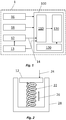
- FIG. 1 shows a schematic diagram of an example of an aircraft landing gear door control system 1 according to an embodiment of the invention.
- the aircraft landing gear door control system 1 comprises an aircraft door controller 100 according to an embodiment of the invention, and a user control 12 configured, when operated by a user, to cause generation of an instruction or command 14 to move an aircraft landing bay door between an open position and a closed position relative to a door frame.
- the aircraft landing gear door control system 1 is independent to a Normal Landing Gear Bay Door Operating System. That is, the aircraft landing gear door control system 1 may be for use only when the aircraft is on the ground, and not for opening and closing the landing gear bay door during landing and take-off.
- the invention may be employed additionally or alternatively to control movement of one or more cargo bay doors, in which case the system comprises an aircraft cargo bay door control system.
- the aircraft door controller 100 is for controlling movement of an aircraft door.
- the controller 100 may be configured to not store information representative of an instruction to move the aircraft door relative to a door frame, in dependence on the availability, at the time when the instruction is received by the controller, of power to perform the instructed movement of the aircraft door.
- the aircraft door control system is configured to allow the aircraft door to be moved towards the open position under the influence of gravity. That is, the door may be locked when in the closed position, and the lock is released to allow the aircraft door to move towards the open position when the command 14 is received and the power is available. Movement of the aircraft door under gravity may be controlled by a damping mechanism. In other embodiments, movement of the aircraft door in each direction between the open position and the closed position may be controlled and effected throughout the full movement of the door by actuation of an actuator.
- the actuator may be, for example, a hydraulic, electro-hydraulic, pneumatic or electro-mechanical actuator.
- the controller 100 comprises a receiver 110 configured to receive the instruction or command 14 to move the aircraft door between the open position and the closed position relative to the door frame.
- the receiver 110 may be configured to receive the command 14 wirelessly.
- the receiver 110 may be configured to receive the command 14 via electrical wiring, or another suitable interface.
- the controller 100 is configured to not store the command 14 when power to move the aircraft door between the open position and the closed position relative to the door frame is unavailable. That is, the controller 100 is configured to not store the command 14 in dependence on the availability, at the time when the instruction 14 is received by the controller 100, of power to perform the instructed movement of the aircraft door. Not storing the instruction or command 14 may comprise not storing information representative of the instruction or command 14. In some examples, when the power is unavailable, the controller 100 is configured to ignore the instruction or command 14.
- the controller 100 is configured to cause movement of the aircraft door between the open position and the closed position relative to the door frame only when the instruction or command 14 is received by the receiver 110 and the power to move the aircraft door between the open position and the closed position relative to the door frame is available.
- the controller 100 of this embodiment comprises a processor 120.
- the processor 120 is configured to receive from the receiver 110 a signal indicative of whether the power is available. In an alternative embodiment, the signal indicative of whether the power is available may be received at the processor 120 from other than the receiver 110.
- the processor 120 may be configured to determine whether the power is available, and to store the command 14 or information representative of the command 14 when the power is available.
- the controller 100 comprises a memory 130, and the processor 120 is configured to store the command 14, or information representative of the command 14, in the memory 130 when the power is available. In other embodiments, the processor 120 may be configured to not store the command 14 or information representative of the command 14, even when the power is available.
- the command 14 comprises an electrical signal.
- the controller 100 is configured to not store the command 14 by the controller 100 not latching the command 14 in the memory 130.
- the user control 12 may be any input device that is operable by a user to cause the command 14 to be sent to the controller 100.
- the user control 12 may comprise a push button, a lever, or a virtual button on a touch screen.
- the user control 12 may be located on a control panel close to the aircraft door.
- the control panel may be located such that the user has a clear line of sight to the area swept by the aircraft door operated by the control panel, whilst the user remains at a safe distance from the aircraft door.
- the user control 12 may be remote from the aircraft door.
- the user control 12 may be configured to cause wireless communication of the command 14 to the controller 100.
- FIG 2 shows a schematic view of an assembly comprising the user control 12 of the system 1 of Figure 1 .
- the user control 12 is configured to cause generation of the command 14 by movement of the user control 12 to a first position, from the position shown in Figure 2 , in the direction indicated by arrow 24.
- the user control 12 of this embodiment is biased away from the first position by a spring 22.
- the user control 12 is moved by the resilience of the spring 22 in the direction indicated by arrow 26, and the command 14 is no longer generated.
- the range of movement of the user input 20 is limited by a housing 28 of the assembly. In this example, the housing helps to ensure that the user control 12 is movable only in the directions indicated by the arrows 24, 26. It will be understood that any other suitable type of biased, or unbiased, user control 12 could be used in other embodiments of the aircraft door control system 10.
- the user control 12 is free to be operated by a user when the power to move the aircraft door between the open position and the closed position relative to the door frame is unavailable.
- the controller 100 is configured such that the command 14 generated by operation of the user control 12 when the power is unavailable is not stored by the controller 100. Accordingly, no interlock, such as that discussed above with reference to the known systems, need be provided to selectively prevent operation of the user control 12.
- the user control 12 is configured to cause generation of the command 14 by movement of the user control 12 to the first position against the biasing force of the spring 22.
- the biasing force causes the user control 12 to tend towards a position at which the command 14 is not caused to be generated.
- the user control 12 cannot, therefore, be inadvertently left by a user in a position at which generation of the command 14 is caused, and will only cause generation of the command 14 when the user control 12 is in the first position.
- the user control 12 cannot inadvertently be left in a position at which movement of the door would be caused, should the power to move the door subsequently be restored.
- the user control 12 is a first user control 12, and the aircraft door control system 1 comprises a second user control 13.
- the aircraft door control system 1 is configured such that actuation of the first user control 12 causes generation of the command 14 in dependence on a status of the second user control 13. More specifically, in this embodiment, actuation of the first user control 12 causes generation of the command 14 only when the second user control 13 is operated simultaneously with the first user control 12.
- the first user control 12 and the second user control 13 are arranged in series, as shown in Figure 1 , such that the first user control 12 can cause generation of the command 14 only when the second user control 13 is actuated simultaneously with the first user control 12.
- the first user control 12 and the second user control 13 are arranged in parallel, so that each of the first and second user controls 12, 13 causes generation of a respective command that is sent to the controller along parallel paths (the path of the command from the second user control shown in Figure 1 by way of a dashed line).
- the controller 100 may be configured to cause movement of the aircraft door between the open position and the closed position relative to the door frame only when the controller 100 receives the commands from both the first user control 12 and the second user control 13 simultaneously.
- the first user control 12 and the second user control 13 are located on a control panel and relatively arranged in such a way that a user cannot operate the first user control 12 and the second user control 13 simultaneously using one hand.
- the control panel may comprise physical barriers which prevent a user reaching both of the first and second user controls 12, 13 simultaneously using one hand, or the first and second user controls 12, 13 may be spaced apart by more than the span of a user's hand. Accordingly, both of the user's hands are required to operate both of the first and second user controls 12, 13 simultaneously.
- Such a configuration helps to ensure that the user cannot trap either of their hands in the aircraft door when the aircraft door moves between the open position and the closed position relative to the door frame in response to the command 14.
- the aircraft door control system 1 further comprises a detector 16 communicatively connected to the controller 100 and configured to detect a position of the aircraft door relative to the door frame.
- the controller 100 is configured to cause movement of the aircraft door between the open position and the closed position relative to the door frame on the basis of an output of the detector 16 received by the controller 100.
- the detector 16 is a proximity sensor.
- any other suitable detector 16 may be employed.
- the detector 16 may be configured to detect when the aircraft door is fully open and/or fully closed.
- the detector 16 may be configured to detect a partially open position of the aircraft door relative to the door frame.
- the receiver 110 may be configured to receive a signal from the detector 16 that is indicative of a position of the aircraft door relative to the door frame.
- the controller 100 may comprise a further receiver for receiving the output of the detector 16.
- the aircraft door control system 1 comprises one or more sensors 18.
- the one or more sensors 18 are configured to detect whether the power to move the aircraft door between the open position and the closed position relative to the door frame is available.
- the one or more sensors 18 may comprise a pressure sensor or other sensor suitable for detecting whether hydraulic power is available.
- the one or more sensors 18 may comprise a voltage detector or other sensor suitable for detecting whether electrical power is available.
- the present invention also provides a method of controlling an aircraft door.
- the method comprises receiving a command to move the aircraft door between an open position and a closed position relative to a door frame, and not storing the command when power to move the aircraft door between the open position and the closed position relative to the door frame is unavailable.
- the method can be carried out by the aircraft door controller 100, whereby the receiver 110 is configured to receive the command to move the aircraft door between an open position and a closed position relative to a door frame and the controller 100 is configured to not store the command 14 when power to move the aircraft door between the open position and the closed position relative to the door frame is unavailable.
- the power comprises hydraulic power.
- the power comprises electrical power.
- the power comprises hydraulic and electrical power
- the method comprises not storing the command when one or each of the hydraulic and electrical power is unavailable.
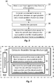
- Figure 3 is a flow diagram showing an example of a method according to an embodiment of the present invention.
- the method can be carried out by use of the aircraft landing gear door control system 1 discussed above.
- the method 30 comprises moving 32 the user control 12 against the biasing force of the spring 22 to a first position, causing 34 generation of the instruction or command 14 to move an aircraft door between an open position and a closed position relative to a door frame, receiving 36 the instruction or command at the controller 100, and not storing 38 the instruction or command or information representative thereof when power to move the aircraft door between the open position and the closed position relative to the door frame is unavailable. That is, the instruction or command is not stored, in dependence on the availability, at the time when the instruction or command is received, of power to perform the instructed movement of the aircraft door.
- the command 14 comprises a command to move the aircraft door from the open position to the closed position relative to the door frame. In other embodiments, the command 14 comprises a command to move the aircraft door from the closed position to the open position relative to the door frame.
- the aircraft door is a landing gear bay door.
- the invention may be employed additionally or alternatively to control movement of one or more cargo bay doors.
- the power may comprise hydraulic and/or electrical power.
- FIG. 4 shows a schematic diagram of a non-transitory computer-readable storage medium according to an embodiment of the invention.
- the non-transitory computer-readable storage medium stores instructions 40 that, if executed by a processor of an aircraft door controller, cause the processor to perform a method of controlling an aircraft door.
- the aircraft door controller, the non-transitory computer-readable storage medium, and the processor are the controller 100, memory 130 and processor 120 of the aircraft landing gear door control system 1 described above with reference to Figures 1 and 2 .
- these elements may additionally or alternatively be parts of an aircraft cargo bay door control system to control movement of one or more cargo bay doors.
- the instructions 40 comprise receiving 41 a command to move the aircraft door between an open position and a closed position relative to a door frame, and not storing 42 the command, when power to move the aircraft door between the open position and the closed position relative to the door frame is unavailable.
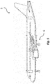
- Figure 5 shows a schematic diagram of an aircraft 5 in accordance with an embodiment of the present invention.
- the aircraft 5 comprises main landing gears 6 and the aircraft landing gear control system 1, comprising the aircraft door controller 100, discussed above for controlling movement of doors of the respective bays for the landing gears 6.
- the aircraft 5 also comprises the non-transitory computer-readable storage medium discussed above with reference to Figure 4 .
- the aircraft 5 comprises at least one cargo bay door and one or more aircraft door control systems according to an embodiment of the invention for controlling movement of the cargo bay door(s).
- the aircraft door may be a cargo bay door or any other aircraft door that can be controlled by the controller 100 or the aircraft door control system 1.
- the aircraft door may be an access hatch for aircraft maintenance.
Landscapes
- Engineering & Computer Science (AREA)
- Aviation & Aerospace Engineering (AREA)
- Mechanical Engineering (AREA)
- Manufacturing & Machinery (AREA)
- Transportation (AREA)
- Physics & Mathematics (AREA)
- General Physics & Mathematics (AREA)
- Power-Operated Mechanisms For Wings (AREA)
Abstract
Description
- The present invention relates to movement of an aircraft door relative to a door frame, such as for access during maintenance procedures. In particular, the invention relates to an aircraft door controller, to an aircraft door control system comprising the aircraft door controller, to a method of controlling an aircraft door, and to an aircraft.
- Opening and closing of an aircraft door, such as a landing gear bay door or a cargo bay door, may be required during a maintenance procedure. At times, power to open or close a door may be unavailable, such as when the door has been isolated from an aircraft power system. It is preferable that the system for controlling the door is unable to cause unexpected movement of the door once power is restored, to help preserve the safety of engineers or technicians working in the vicinity of the door.
- A first aspect of the present invention provides an aircraft door controller comprising a receiver configured to receive a command to move an aircraft door between an open position and a closed position relative to a door frame, wherein the aircraft door controller is configured to not store the command when power to move the aircraft door between the open position and the closed position relative to the door frame is unavailable.
- Optionally, the command comprises an electrical signal.
- Optionally, the controller is configured to not store the command by the controller not latching the command in memory.
- A second aspect of the present invention provides an aircraft door control system, comprising a controller according to the first aspect of the invention, and a user input configured to cause generation of the command when operated by a user.
- Optionally, the user control is operable by the user when the power to move the aircraft door between the open position and the closed position relative to the door frame is unavailable.
- Optionally, wherein the user control is configured to cause generation of the command by movement of the user control to a first position, and wherein the user control is biased away from the first position.
- Optionally, the aircraft door control system comprises a detector configured to detect a position of the aircraft door relative to the door frame, and the aircraft door controller is configured to cause movement of the aircraft door between the open position and the closed position relative to the door frame on the basis of an output of the detector.
- Optionally, the user control is a first user control and the control system comprises a second user control, and the aircraft door control system is configured such that operation of the first user control causes generation of the command in dependence on a status of the second user control.
- Optionally, the aircraft door control system is an aircraft landing gear bay door control system.
- A third aspect of the present invention provides a method of controlling an aircraft door, the method comprising receiving a command to move the aircraft door between an open position and a closed position relative to a door frame and not storing the command, when power to move the aircraft door between the open position and the closed position relative to the door frame is unavailable.
- Optionally, the command is generated by actuation of a user control, and the user control is free to be actuated when the power to move the aircraft door between the open position and the closed position relative to the door frame is unavailable.
- Optionally, the command is generated by movement of the user control to a first position against a biasing force.
- Optionally, the command comprises an electrical signal.
- Optionally, the not storing the command comprises not latching the electrical signal in memory.
- Optionally, the command comprises a command to move the aircraft door from the open position to the closed position relative to the door frame.
- Optionally, the power comprises hydraulic power and/or electrical power.
- Optionally, the aircraft door is a landing gear bay door or a cargo bay door.
- A fourth aspect of the present invention provides a non-transitory computer-readable storage medium storing instructions that, if executed by a processor of an aircraft door controller, cause the processor to carry out the method according to the third aspect of the present invention.
- A fifth aspect of the present invention provides an aircraft comprising one or more of: an aircraft door controller according to the first aspect of the present invention, an aircraft door control system according to the second aspect of the present invention, and a non-transitory computer-readable storage medium according to the third aspect of the present invention.
- A sixth aspect of the present invention provides an aircraft door controller for controlling movement of an aircraft door, wherein the aircraft door controller is configured to not store information representative of an instruction to move the aircraft door relative to a door frame, in dependence on the availability, at the time when the instruction is received by the controller, of power to perform the instructed movement of the aircraft door.
- Optionally, the instruction comprises an electrical signal.
- Optionally, the controller is configured to not store the information by not latching the instruction in memory.
- It is to be noted that, herein, the phrase "between the open position and the closed position" covers movement from the open position to the closed position, and movement from the closed position to the open position. In some embodiments, the movement is from the open position to the closed position, and in other embodiments the movement is from the closed position to the open position.
- It is also to be noted that, herein, reference to storing or not storing a command or instruction may comprise storing or not storing, respectively, information representative of the command or instruction.
- Embodiments of the invention will now be described, by way of example only, with reference to the accompanying drawings, in which:
-
Figure 1 shows a schematic view of an example of an aircraft landing gear door control system according to an embodiment of the invention; -
Figure 2 shows a schematic view of an assembly comprising a user control of the system ofFigure 1 ; -
Figure 3 is a flow diagram showing an example of a method of controlling an aircraft door according an embodiment of the invention; -
Figure 4 shows a schematic diagram of an example of a non-transitory computer-readable storage medium according to an embodiment of the invention; and -
Figure 5 shows a schematic side view of an example of an aircraft according to an embodiment of the invention. - The following description relates to controllers, control systems and methods for controlling movement of an aircraft door between an open position and a closed position relative to a door frame.
- In known systems, a command to move an aircraft door between an open position and a closed position relative to a door frame is generated by user-operation of an actuator, such as a lever. When power to move the aircraft door is unavailable, an interlock prevents a user from actuating the actuator, so that the command cannot be generated. When power to move the aircraft door is restored, the interlock is released so that the actuator is then free to be actuated to cause generation of the command. Such systems can be relatively large and heavy, with a relatively high number of moving parts. However, there is a general inertia in the aircraft industry to continue using such systems, as they are perceived to have a degree of reliability that outweighs their disadvantageous size and weight.
-
Figure 1 shows a schematic diagram of an example of an aircraft landing geardoor control system 1 according to an embodiment of the invention. The aircraft landing geardoor control system 1 comprises anaircraft door controller 100 according to an embodiment of the invention, and auser control 12 configured, when operated by a user, to cause generation of an instruction orcommand 14 to move an aircraft landing bay door between an open position and a closed position relative to a door frame. - In some embodiments, the aircraft landing gear
door control system 1 is independent to a Normal Landing Gear Bay Door Operating System. That is, the aircraft landing geardoor control system 1 may be for use only when the aircraft is on the ground, and not for opening and closing the landing gear bay door during landing and take-off. - It will be understood that in other embodiments the invention may be employed additionally or alternatively to control movement of one or more cargo bay doors, in which case the system comprises an aircraft cargo bay door control system.
- In some embodiments, the
aircraft door controller 100 is for controlling movement of an aircraft door. Thecontroller 100 may be configured to not store information representative of an instruction to move the aircraft door relative to a door frame, in dependence on the availability, at the time when the instruction is received by the controller, of power to perform the instructed movement of the aircraft door. - In some embodiments, particularly those in which the aircraft door is moveable using an electro-hydraulic actuator, the aircraft door control system is configured to allow the aircraft door to be moved towards the open position under the influence of gravity. That is, the door may be locked when in the closed position, and the lock is released to allow the aircraft door to move towards the open position when the
command 14 is received and the power is available. Movement of the aircraft door under gravity may be controlled by a damping mechanism. In other embodiments, movement of the aircraft door in each direction between the open position and the closed position may be controlled and effected throughout the full movement of the door by actuation of an actuator. The actuator may be, for example, a hydraulic, electro-hydraulic, pneumatic or electro-mechanical actuator. - Broadly speaking, the
controller 100 comprises areceiver 110 configured to receive the instruction orcommand 14 to move the aircraft door between the open position and the closed position relative to the door frame. Thereceiver 110 may be configured to receive thecommand 14 wirelessly. Alternatively, thereceiver 110 may be configured to receive thecommand 14 via electrical wiring, or another suitable interface. Thecontroller 100 is configured to not store thecommand 14 when power to move the aircraft door between the open position and the closed position relative to the door frame is unavailable. That is, thecontroller 100 is configured to not store thecommand 14 in dependence on the availability, at the time when theinstruction 14 is received by thecontroller 100, of power to perform the instructed movement of the aircraft door. Not storing the instruction orcommand 14 may comprise not storing information representative of the instruction orcommand 14. In some examples, when the power is unavailable, thecontroller 100 is configured to ignore the instruction orcommand 14. - In this embodiment, the
controller 100 is configured to cause movement of the aircraft door between the open position and the closed position relative to the door frame only when the instruction orcommand 14 is received by thereceiver 110 and the power to move the aircraft door between the open position and the closed position relative to the door frame is available. - The
controller 100 of this embodiment comprises aprocessor 120. Theprocessor 120 is configured to receive from the receiver 110 a signal indicative of whether the power is available. In an alternative embodiment, the signal indicative of whether the power is available may be received at theprocessor 120 from other than thereceiver 110. In some embodiments, theprocessor 120 may be configured to determine whether the power is available, and to store thecommand 14 or information representative of thecommand 14 when the power is available. In this embodiment, thecontroller 100 comprises amemory 130, and theprocessor 120 is configured to store thecommand 14, or information representative of thecommand 14, in thememory 130 when the power is available. In other embodiments, theprocessor 120 may be configured to not store thecommand 14 or information representative of thecommand 14, even when the power is available. - In this embodiment, the
command 14 comprises an electrical signal. Further, in this embodiment, thecontroller 100 is configured to not store thecommand 14 by thecontroller 100 not latching thecommand 14 in thememory 130. - In embodiments of the present invention, the
user control 12 may be any input device that is operable by a user to cause thecommand 14 to be sent to thecontroller 100. For example, theuser control 12 may comprise a push button, a lever, or a virtual button on a touch screen. Theuser control 12 may be located on a control panel close to the aircraft door. The control panel may be located such that the user has a clear line of sight to the area swept by the aircraft door operated by the control panel, whilst the user remains at a safe distance from the aircraft door. Alternatively, theuser control 12 may be remote from the aircraft door. Theuser control 12 may be configured to cause wireless communication of thecommand 14 to thecontroller 100. -
Figure 2 shows a schematic view of an assembly comprising theuser control 12 of thesystem 1 ofFigure 1 . Theuser control 12 is configured to cause generation of thecommand 14 by movement of theuser control 12 to a first position, from the position shown inFigure 2 , in the direction indicated byarrow 24. Theuser control 12 of this embodiment is biased away from the first position by aspring 22. When the user releases theuser control 12, theuser control 12 is moved by the resilience of thespring 22 in the direction indicated byarrow 26, and thecommand 14 is no longer generated. The range of movement of the user input 20 is limited by ahousing 28 of the assembly. In this example, the housing helps to ensure that theuser control 12 is movable only in the directions indicated by thearrows user control 12 could be used in other embodiments of the aircraft door control system 10. - In this embodiment, and in contrast to the known systems discussed above, the
user control 12 is free to be operated by a user when the power to move the aircraft door between the open position and the closed position relative to the door frame is unavailable. Thecontroller 100 is configured such that thecommand 14 generated by operation of theuser control 12 when the power is unavailable is not stored by thecontroller 100. Accordingly, no interlock, such as that discussed above with reference to the known systems, need be provided to selectively prevent operation of theuser control 12. - As noted above, the
user control 12 is configured to cause generation of thecommand 14 by movement of theuser control 12 to the first position against the biasing force of thespring 22. The biasing force causes theuser control 12 to tend towards a position at which thecommand 14 is not caused to be generated. Theuser control 12 cannot, therefore, be inadvertently left by a user in a position at which generation of thecommand 14 is caused, and will only cause generation of thecommand 14 when theuser control 12 is in the first position. As such, theuser control 12 cannot inadvertently be left in a position at which movement of the door would be caused, should the power to move the door subsequently be restored. - In this embodiment, the
user control 12 is afirst user control 12, and the aircraftdoor control system 1 comprises a second user control 13. The aircraftdoor control system 1 is configured such that actuation of thefirst user control 12 causes generation of thecommand 14 in dependence on a status of the second user control 13. More specifically, in this embodiment, actuation of thefirst user control 12 causes generation of thecommand 14 only when the second user control 13 is operated simultaneously with thefirst user control 12. In some embodiments, thefirst user control 12 and the second user control 13 are arranged in series, as shown inFigure 1 , such that thefirst user control 12 can cause generation of thecommand 14 only when the second user control 13 is actuated simultaneously with thefirst user control 12. In other embodiments, thefirst user control 12 and the second user control 13 are arranged in parallel, so that each of the first and second user controls 12, 13 causes generation of a respective command that is sent to the controller along parallel paths (the path of the command from the second user control shown inFigure 1 by way of a dashed line). In such alternative embodiments, thecontroller 100 may be configured to cause movement of the aircraft door between the open position and the closed position relative to the door frame only when thecontroller 100 receives the commands from both thefirst user control 12 and the second user control 13 simultaneously. - In some embodiments, the
first user control 12 and the second user control 13 are located on a control panel and relatively arranged in such a way that a user cannot operate thefirst user control 12 and the second user control 13 simultaneously using one hand. For example, the control panel may comprise physical barriers which prevent a user reaching both of the first and second user controls 12, 13 simultaneously using one hand, or the first and second user controls 12, 13 may be spaced apart by more than the span of a user's hand. Accordingly, both of the user's hands are required to operate both of the first and second user controls 12, 13 simultaneously. Such a configuration helps to ensure that the user cannot trap either of their hands in the aircraft door when the aircraft door moves between the open position and the closed position relative to the door frame in response to thecommand 14. - In this embodiment, the aircraft
door control system 1 further comprises adetector 16 communicatively connected to thecontroller 100 and configured to detect a position of the aircraft door relative to the door frame. Thecontroller 100 is configured to cause movement of the aircraft door between the open position and the closed position relative to the door frame on the basis of an output of thedetector 16 received by thecontroller 100. In this embodiment, thedetector 16 is a proximity sensor. However, it will be appreciated that in other embodiments any othersuitable detector 16 may be employed. Thedetector 16 may be configured to detect when the aircraft door is fully open and/or fully closed. Thedetector 16 may be configured to detect a partially open position of the aircraft door relative to the door frame. Thereceiver 110 may be configured to receive a signal from thedetector 16 that is indicative of a position of the aircraft door relative to the door frame. In other embodiments, thecontroller 100 may comprise a further receiver for receiving the output of thedetector 16. - In this embodiment, the aircraft
door control system 1 comprises one ormore sensors 18. The one ormore sensors 18 are configured to detect whether the power to move the aircraft door between the open position and the closed position relative to the door frame is available. In embodiments in which the power comprises hydraulic power, the one ormore sensors 18 may comprise a pressure sensor or other sensor suitable for detecting whether hydraulic power is available. In embodiments in which the power comprises electrical power, the one ormore sensors 18 may comprise a voltage detector or other sensor suitable for detecting whether electrical power is available. - The present invention also provides a method of controlling an aircraft door. The method comprises receiving a command to move the aircraft door between an open position and a closed position relative to a door frame, and not storing the command when power to move the aircraft door between the open position and the closed position relative to the door frame is unavailable. The method can be carried out by the
aircraft door controller 100, whereby thereceiver 110 is configured to receive the command to move the aircraft door between an open position and a closed position relative to a door frame and thecontroller 100 is configured to not store thecommand 14 when power to move the aircraft door between the open position and the closed position relative to the door frame is unavailable. In some embodiments, the power comprises hydraulic power. In some embodiments, the power comprises electrical power. In some embodiments, the power comprises hydraulic and electrical power, and the method comprises not storing the command when one or each of the hydraulic and electrical power is unavailable. -
Figure 3 is a flow diagram showing an example of a method according to an embodiment of the present invention. The method can be carried out by use of the aircraft landing geardoor control system 1 discussed above. Themethod 30 comprises moving 32 theuser control 12 against the biasing force of thespring 22 to a first position, causing 34 generation of the instruction orcommand 14 to move an aircraft door between an open position and a closed position relative to a door frame, receiving 36 the instruction or command at thecontroller 100, and not storing 38 the instruction or command or information representative thereof when power to move the aircraft door between the open position and the closed position relative to the door frame is unavailable. That is, the instruction or command is not stored, in dependence on the availability, at the time when the instruction or command is received, of power to perform the instructed movement of the aircraft door. In some embodiments, thecommand 14 comprises a command to move the aircraft door from the open position to the closed position relative to the door frame. In other embodiments, thecommand 14 comprises a command to move the aircraft door from the closed position to the open position relative to the door frame. In this embodiment, the aircraft door is a landing gear bay door. However, as noted elsewhere herein, in other embodiments the invention may be employed additionally or alternatively to control movement of one or more cargo bay doors. As noted above, the power may comprise hydraulic and/or electrical power. -
Figure 4 shows a schematic diagram of a non-transitory computer-readable storage medium according to an embodiment of the invention. The non-transitory computer-readable storagemedium stores instructions 40 that, if executed by a processor of an aircraft door controller, cause the processor to perform a method of controlling an aircraft door. In this embodiment, the aircraft door controller, the non-transitory computer-readable storage medium, and the processor are thecontroller 100,memory 130 andprocessor 120 of the aircraft landing geardoor control system 1 described above with reference toFigures 1 and 2 . However, in other embodiments, these elements may additionally or alternatively be parts of an aircraft cargo bay door control system to control movement of one or more cargo bay doors. In either case, theinstructions 40 comprise receiving 41 a command to move the aircraft door between an open position and a closed position relative to a door frame, and not storing 42 the command, when power to move the aircraft door between the open position and the closed position relative to the door frame is unavailable. -
Figure 5 shows a schematic diagram of anaircraft 5 in accordance with an embodiment of the present invention. In this embodiment, theaircraft 5 comprises main landing gears 6 and the aircraft landinggear control system 1, comprising theaircraft door controller 100, discussed above for controlling movement of doors of the respective bays for the landing gears 6. Theaircraft 5 also comprises the non-transitory computer-readable storage medium discussed above with reference toFigure 4 . In some embodiments, theaircraft 5 comprises at least one cargo bay door and one or more aircraft door control systems according to an embodiment of the invention for controlling movement of the cargo bay door(s). - The above embodiments are to be understood as non-limiting illustrative examples of how the present invention, and aspects of the present invention, may be implemented. Further examples of the invention are envisaged. For example, the aircraft door may be a cargo bay door or any other aircraft door that can be controlled by the
controller 100 or the aircraftdoor control system 1. For example, the aircraft door may be an access hatch for aircraft maintenance. It is to be understood that any feature described in relation to any one embodiment may be used alone, or in combination with other features described, and may also be used in combination with one or more features of any other of the embodiments, or any combination of any other of the embodiments. Furthermore, equivalents and modifications not described above may also be employed without departing from the scope of the invention, which is defined in the accompanying claims. - It is to noted that the term "or" as used herein is to be interpreted to mean "and/or", unless expressly stated otherwise.
Claims (15)
- An aircraft door controller, comprising:a receiver configured to receive a command to move an aircraft door between an open position and a closed position relative to a door frame;wherein the aircraft door controller is configured to not store the command when power to move the aircraft door between the open position and the closed position relative to the door frame is unavailable.
- The aircraft door controller according to claim 1, wherein the command comprises an electrical signal,
optionally, wherein the controller is configured to not store the command by the controller not latching the command in memory. - An aircraft door control system, comprising:the aircraft door controller according to claim 1 or claim 2; anda user control configured to cause generation of the command when operated by a user.
- The aircraft door control system according to claim 3, wherein the user control is operable by the user when the power to move the aircraft door between the open position and the closed position relative to the door frame is unavailable,
optionally, wherein the user control is configured to cause generation of the command by movement of the user control to a first position, and wherein the user control is biased away from the first position. - The aircraft door control system according to claim 3 or claim 4, comprising a detector configured to detect a position of the aircraft door relative to the door frame, wherein the aircraft door controller is configured to cause movement of the aircraft door between the open position and the closed position relative to the door frame on the basis of an output of the detector.
- The aircraft door control system according to any one of claims 3 to 5, wherein the user control is a first user control and the control system comprises a second user control, and
wherein the aircraft door control system is configured such that operation of the first user control causes generation of the command in dependence on a status of the second user control. - The aircraft door control system according to any one of claims 3 to 6, wherein the aircraft door control system is an aircraft landing gear bay door control system.
- A method of controlling an aircraft door, the method comprising:receiving a command to move the aircraft door between an open position and a closed position relative to a door frame; andnot storing the command, when power to move the aircraft door between the open position and the closed position relative to the door frame is unavailable.
- The method according to claim 8, comprising causing generation of the command by operation of a user control, and
wherein the user control is operable to cause generation of the command when the power to move the aircraft door between the open position and the closed position relative to the door frame is unavailable. - The method according to claim 8 or claim 9, wherein the command comprises a command to move the aircraft door from the open position to the closed position relative to the door frame.
- The method according to any one of claims 8 to 10, wherein the power comprises hydraulic power and/or electrical power.
- The method according to any one of claims 8 to 11, wherein the aircraft door is a landing gear bay door or a cargo bay door.
- A non-transitory computer-readable storage medium storing instructions that, if executed by a processor of an aircraft door controller, cause the processor to carry out the method of any one of claims 8 to 12.
- An aircraft, comprising one or more of:the aircraft door controller according to claim 1 or claim 2;the aircraft door control system according to any one of claims 3 to 7; andthe non-transitory computer-readable storage medium according to claim 13.
- An aircraft door controller for controlling movement of an aircraft door, wherein the aircraft door controller is configured to not store information representative of an instruction to move the aircraft door relative to a door frame, in dependence on the availability, at the time when the instruction is received by the controller, of power to perform the instructed movement of the aircraft door.
Applications Claiming Priority (1)
| Application Number | Priority Date | Filing Date | Title |
|---|---|---|---|
| GB1707777.7A GB2562485A (en) | 2017-05-15 | 2017-05-15 | Aircraft door control |
Publications (2)
| Publication Number | Publication Date |
|---|---|
| EP3403920A1 true EP3403920A1 (en) | 2018-11-21 |
| EP3403920B1 EP3403920B1 (en) | 2022-07-06 |
Family
ID=59201448
Family Applications (1)
| Application Number | Title | Priority Date | Filing Date |
|---|---|---|---|
| EP18172285.1A Active EP3403920B1 (en) | 2017-05-15 | 2018-05-15 | Aircraft door control |
Country Status (3)
| Country | Link |
|---|---|
| US (1) | US11420720B2 (en) |
| EP (1) | EP3403920B1 (en) |
| GB (1) | GB2562485A (en) |
Families Citing this family (6)
| Publication number | Priority date | Publication date | Assignee | Title |
|---|---|---|---|---|
| US10974852B2 (en) * | 2019-02-19 | 2021-04-13 | The Boeing Company | Aircraft landing gear monitoring systems and methods |
| GB2581824A (en) * | 2019-02-28 | 2020-09-02 | Airbus Operations Ltd | Landing gear control |
| CN110001917B (en) * | 2019-03-20 | 2022-05-27 | 庆安集团有限公司 | Control method for freight system of civil cargo aircraft |
| CN111119647B (en) * | 2019-12-24 | 2021-09-14 | 中国航空工业集团公司西安飞机设计研究所 | State conversion control method for side cabin door of transport-type airplane |
| CN112937841B (en) * | 2021-03-04 | 2022-07-05 | 中国商用飞机有限责任公司 | Landing gear and hatch door control system and control method |
| CN113911387B (en) * | 2021-09-13 | 2023-09-29 | 北京精密机电控制设备研究所 | Cam type aircraft cabin door load simulation device and simulation method |
Citations (6)
| Publication number | Priority date | Publication date | Assignee | Title |
|---|---|---|---|---|
| US4573649A (en) * | 1983-08-01 | 1986-03-04 | The Boeing Company | Integrated alternate gear extension and ground-crew door opening/closing system for an aircraft |
| WO1998017528A1 (en) * | 1996-10-24 | 1998-04-30 | Mcdonnel Douglas Corporation | Plug door operating mechanism |
| FR2875475A1 (en) * | 2004-09-21 | 2006-03-24 | Airbus France Sas | SYSTEM FOR MANEUVERING A LANDING TRAIN FOR AN AIRCRAFT AND AN AIRCRAFT HAVING SUCH A SYSTEM |
| JP2007120239A (en) * | 2005-10-31 | 2007-05-17 | Mitsui Mining & Smelting Co Ltd | Door opening / closing control device |
| EP2572981A1 (en) * | 2011-09-26 | 2013-03-27 | Messier-Bugatti-Dowty | Device for operating the door of an aircraft landing gear on the ground |
| US20130264418A1 (en) * | 2011-12-15 | 2013-10-10 | Messier-Bugatti-Dowty | Method of managing systems associated with the landing gear of an aircraft |
Family Cites Families (4)
| Publication number | Priority date | Publication date | Assignee | Title |
|---|---|---|---|---|
| US7181369B2 (en) * | 2001-06-15 | 2007-02-20 | Nabco, Ltd. | Method and system for administering automatic door apparatus, and automatic door apparatus |
| US20090006846A1 (en) * | 2007-06-27 | 2009-01-01 | Apple Inc. | Bluetooth device as security access key |
| JP2012195687A (en) * | 2011-03-15 | 2012-10-11 | Tokai Rika Co Ltd | Transmitter, receiver, and communication system |
| US20140155827A1 (en) * | 2012-12-03 | 2014-06-05 | Mylan, Inc. | Medicament information system and method |
-
2017
- 2017-05-15 GB GB1707777.7A patent/GB2562485A/en not_active Withdrawn
-
2018
- 2018-05-15 US US15/980,004 patent/US11420720B2/en active Active
- 2018-05-15 EP EP18172285.1A patent/EP3403920B1/en active Active
Patent Citations (6)
| Publication number | Priority date | Publication date | Assignee | Title |
|---|---|---|---|---|
| US4573649A (en) * | 1983-08-01 | 1986-03-04 | The Boeing Company | Integrated alternate gear extension and ground-crew door opening/closing system for an aircraft |
| WO1998017528A1 (en) * | 1996-10-24 | 1998-04-30 | Mcdonnel Douglas Corporation | Plug door operating mechanism |
| FR2875475A1 (en) * | 2004-09-21 | 2006-03-24 | Airbus France Sas | SYSTEM FOR MANEUVERING A LANDING TRAIN FOR AN AIRCRAFT AND AN AIRCRAFT HAVING SUCH A SYSTEM |
| JP2007120239A (en) * | 2005-10-31 | 2007-05-17 | Mitsui Mining & Smelting Co Ltd | Door opening / closing control device |
| EP2572981A1 (en) * | 2011-09-26 | 2013-03-27 | Messier-Bugatti-Dowty | Device for operating the door of an aircraft landing gear on the ground |
| US20130264418A1 (en) * | 2011-12-15 | 2013-10-10 | Messier-Bugatti-Dowty | Method of managing systems associated with the landing gear of an aircraft |
Also Published As
| Publication number | Publication date |
|---|---|
| EP3403920B1 (en) | 2022-07-06 |
| GB2562485A (en) | 2018-11-21 |
| US20180327073A1 (en) | 2018-11-15 |
| US11420720B2 (en) | 2022-08-23 |
| GB201707777D0 (en) | 2017-06-28 |
Similar Documents
| Publication | Publication Date | Title |
|---|---|---|
| US11420720B2 (en) | Aircraft door control | |
| EP3863924B1 (en) | Landing gear system uplock arrangement | |
| US20170226788A1 (en) | Vehicle closure member power actuator control | |
| CN111824396B (en) | System and method for landing gear retraction | |
| US9897116B2 (en) | Method of detecting failure of a servo-valve, and a servo-valve applying the method | |
| EP2905410B1 (en) | Opening and closing body control method and apparatus | |
| US20150360545A1 (en) | Vehicle Anti-Pinch Moonroof Control System and Method | |
| EP3702273B1 (en) | Landing gear system operation | |
| EP3659910B1 (en) | Jam mitigation in aircraft fly-by-wire systems and related methods | |
| EP3220221B1 (en) | Testing of safety devices | |
| US4476678A (en) | Control mechanism for pneumatic apparatus | |
| EP3064853B1 (en) | Hvac damper control | |
| GB2594012A (en) | A door system, a vehicle and a method of providing a barrier | |
| GB2594193A (en) | A door system and method of providing a barrier to entry into a cabin of a vehicle | |
| EP3392189B1 (en) | Method and apparatus for stall control of elevator door | |
| US9139280B2 (en) | Control box | |
| US20190263507A1 (en) | System for moving an aircraft door | |
| EP3293146B1 (en) | Mechanical lifting device for vehicles | |
| CN112041529B (en) | Control device and method for controlling a window lifter with anti-pinch protection for a motor vehicle | |
| US20180155034A1 (en) | Aircraft seat and method for adjusting an aircraft seat | |
| JP2006142869A (en) | Aircraft leg lift system | |
| EP2907748A1 (en) | Aircraft or aircraft section comprising a bay, and method of operating the same | |
| US20140007757A1 (en) | Bomb Rack Lock | |
| US20140216236A1 (en) | Bomb rack lock | |
| GB2562273A (en) | A control system for a vehicle bonnet closure-release system |
Legal Events
| Date | Code | Title | Description |
|---|---|---|---|
| PUAI | Public reference made under article 153(3) epc to a published international application that has entered the european phase |
Free format text: ORIGINAL CODE: 0009012 |
|
| STAA | Information on the status of an ep patent application or granted ep patent |
Free format text: STATUS: THE APPLICATION HAS BEEN PUBLISHED |
|
| AK | Designated contracting states |
Kind code of ref document: A1 Designated state(s): AL AT BE BG CH CY CZ DE DK EE ES FI FR GB GR HR HU IE IS IT LI LT LU LV MC MK MT NL NO PL PT RO RS SE SI SK SM TR |
|
| AX | Request for extension of the european patent |
Extension state: BA ME |
|
| STAA | Information on the status of an ep patent application or granted ep patent |
Free format text: STATUS: REQUEST FOR EXAMINATION WAS MADE |
|
| 17P | Request for examination filed |
Effective date: 20190521 |
|
| RBV | Designated contracting states (corrected) |
Designated state(s): AL AT BE BG CH CY CZ DE DK EE ES FI FR GB GR HR HU IE IS IT LI LT LU LV MC MK MT NL NO PL PT RO RS SE SI SK SM TR |
|
| STAA | Information on the status of an ep patent application or granted ep patent |
Free format text: STATUS: EXAMINATION IS IN PROGRESS |
|
| 17Q | First examination report despatched |
Effective date: 20210407 |
|
| GRAP | Despatch of communication of intention to grant a patent |
Free format text: ORIGINAL CODE: EPIDOSNIGR1 |
|
| STAA | Information on the status of an ep patent application or granted ep patent |
Free format text: STATUS: GRANT OF PATENT IS INTENDED |
|
| INTG | Intention to grant announced |
Effective date: 20220107 |
|
| GRAS | Grant fee paid |
Free format text: ORIGINAL CODE: EPIDOSNIGR3 |
|
| GRAA | (expected) grant |
Free format text: ORIGINAL CODE: 0009210 |
|
| STAA | Information on the status of an ep patent application or granted ep patent |
Free format text: STATUS: THE PATENT HAS BEEN GRANTED |
|
| AK | Designated contracting states |
Kind code of ref document: B1 Designated state(s): AL AT BE BG CH CY CZ DE DK EE ES FI FR GB GR HR HU IE IS IT LI LT LU LV MC MK MT NL NO PL PT RO RS SE SI SK SM TR |
|
| REG | Reference to a national code |
Ref country code: AT Ref legal event code: REF Ref document number: 1502700 Country of ref document: AT Kind code of ref document: T Effective date: 20220715 Ref country code: CH Ref legal event code: EP |
|
| REG | Reference to a national code |
Ref country code: DE Ref legal event code: R096 Ref document number: 602018037489 Country of ref document: DE |
|
| REG | Reference to a national code |
Ref country code: IE Ref legal event code: FG4D |
|
| REG | Reference to a national code |
Ref country code: LT Ref legal event code: MG9D |
|
| REG | Reference to a national code |
Ref country code: NL Ref legal event code: MP Effective date: 20220706 |
|
| PG25 | Lapsed in a contracting state [announced via postgrant information from national office to epo] |
Ref country code: SE Free format text: LAPSE BECAUSE OF FAILURE TO SUBMIT A TRANSLATION OF THE DESCRIPTION OR TO PAY THE FEE WITHIN THE PRESCRIBED TIME-LIMIT Effective date: 20220706 Ref country code: RS Free format text: LAPSE BECAUSE OF FAILURE TO SUBMIT A TRANSLATION OF THE DESCRIPTION OR TO PAY THE FEE WITHIN THE PRESCRIBED TIME-LIMIT Effective date: 20220706 Ref country code: PT Free format text: LAPSE BECAUSE OF FAILURE TO SUBMIT A TRANSLATION OF THE DESCRIPTION OR TO PAY THE FEE WITHIN THE PRESCRIBED TIME-LIMIT Effective date: 20221107 Ref country code: NO Free format text: LAPSE BECAUSE OF FAILURE TO SUBMIT A TRANSLATION OF THE DESCRIPTION OR TO PAY THE FEE WITHIN THE PRESCRIBED TIME-LIMIT Effective date: 20221006 Ref country code: NL Free format text: LAPSE BECAUSE OF FAILURE TO SUBMIT A TRANSLATION OF THE DESCRIPTION OR TO PAY THE FEE WITHIN THE PRESCRIBED TIME-LIMIT Effective date: 20220706 Ref country code: LV Free format text: LAPSE BECAUSE OF FAILURE TO SUBMIT A TRANSLATION OF THE DESCRIPTION OR TO PAY THE FEE WITHIN THE PRESCRIBED TIME-LIMIT Effective date: 20220706 Ref country code: LT Free format text: LAPSE BECAUSE OF FAILURE TO SUBMIT A TRANSLATION OF THE DESCRIPTION OR TO PAY THE FEE WITHIN THE PRESCRIBED TIME-LIMIT Effective date: 20220706 Ref country code: FI Free format text: LAPSE BECAUSE OF FAILURE TO SUBMIT A TRANSLATION OF THE DESCRIPTION OR TO PAY THE FEE WITHIN THE PRESCRIBED TIME-LIMIT Effective date: 20220706 Ref country code: ES Free format text: LAPSE BECAUSE OF FAILURE TO SUBMIT A TRANSLATION OF THE DESCRIPTION OR TO PAY THE FEE WITHIN THE PRESCRIBED TIME-LIMIT Effective date: 20220706 |
|
| REG | Reference to a national code |
Ref country code: AT Ref legal event code: MK05 Ref document number: 1502700 Country of ref document: AT Kind code of ref document: T Effective date: 20220706 |
|
| PG25 | Lapsed in a contracting state [announced via postgrant information from national office to epo] |
Ref country code: PL Free format text: LAPSE BECAUSE OF FAILURE TO SUBMIT A TRANSLATION OF THE DESCRIPTION OR TO PAY THE FEE WITHIN THE PRESCRIBED TIME-LIMIT Effective date: 20220706 Ref country code: IS Free format text: LAPSE BECAUSE OF FAILURE TO SUBMIT A TRANSLATION OF THE DESCRIPTION OR TO PAY THE FEE WITHIN THE PRESCRIBED TIME-LIMIT Effective date: 20221106 Ref country code: HR Free format text: LAPSE BECAUSE OF FAILURE TO SUBMIT A TRANSLATION OF THE DESCRIPTION OR TO PAY THE FEE WITHIN THE PRESCRIBED TIME-LIMIT Effective date: 20220706 Ref country code: GR Free format text: LAPSE BECAUSE OF FAILURE TO SUBMIT A TRANSLATION OF THE DESCRIPTION OR TO PAY THE FEE WITHIN THE PRESCRIBED TIME-LIMIT Effective date: 20221007 |
|
| REG | Reference to a national code |
Ref country code: DE Ref legal event code: R097 Ref document number: 602018037489 Country of ref document: DE |
|
| PG25 | Lapsed in a contracting state [announced via postgrant information from national office to epo] |
Ref country code: SM Free format text: LAPSE BECAUSE OF FAILURE TO SUBMIT A TRANSLATION OF THE DESCRIPTION OR TO PAY THE FEE WITHIN THE PRESCRIBED TIME-LIMIT Effective date: 20220706 Ref country code: RO Free format text: LAPSE BECAUSE OF FAILURE TO SUBMIT A TRANSLATION OF THE DESCRIPTION OR TO PAY THE FEE WITHIN THE PRESCRIBED TIME-LIMIT Effective date: 20220706 Ref country code: DK Free format text: LAPSE BECAUSE OF FAILURE TO SUBMIT A TRANSLATION OF THE DESCRIPTION OR TO PAY THE FEE WITHIN THE PRESCRIBED TIME-LIMIT Effective date: 20220706 Ref country code: CZ Free format text: LAPSE BECAUSE OF FAILURE TO SUBMIT A TRANSLATION OF THE DESCRIPTION OR TO PAY THE FEE WITHIN THE PRESCRIBED TIME-LIMIT Effective date: 20220706 Ref country code: AT Free format text: LAPSE BECAUSE OF FAILURE TO SUBMIT A TRANSLATION OF THE DESCRIPTION OR TO PAY THE FEE WITHIN THE PRESCRIBED TIME-LIMIT Effective date: 20220706 |
|
| PLBE | No opposition filed within time limit |
Free format text: ORIGINAL CODE: 0009261 |
|
| STAA | Information on the status of an ep patent application or granted ep patent |
Free format text: STATUS: NO OPPOSITION FILED WITHIN TIME LIMIT |
|
| PG25 | Lapsed in a contracting state [announced via postgrant information from national office to epo] |
Ref country code: SK Free format text: LAPSE BECAUSE OF FAILURE TO SUBMIT A TRANSLATION OF THE DESCRIPTION OR TO PAY THE FEE WITHIN THE PRESCRIBED TIME-LIMIT Effective date: 20220706 Ref country code: EE Free format text: LAPSE BECAUSE OF FAILURE TO SUBMIT A TRANSLATION OF THE DESCRIPTION OR TO PAY THE FEE WITHIN THE PRESCRIBED TIME-LIMIT Effective date: 20220706 |
|
| 26N | No opposition filed |
Effective date: 20230411 |
|
| PG25 | Lapsed in a contracting state [announced via postgrant information from national office to epo] |
Ref country code: AL Free format text: LAPSE BECAUSE OF FAILURE TO SUBMIT A TRANSLATION OF THE DESCRIPTION OR TO PAY THE FEE WITHIN THE PRESCRIBED TIME-LIMIT Effective date: 20220706 |
|
| PG25 | Lapsed in a contracting state [announced via postgrant information from national office to epo] |
Ref country code: SI Free format text: LAPSE BECAUSE OF FAILURE TO SUBMIT A TRANSLATION OF THE DESCRIPTION OR TO PAY THE FEE WITHIN THE PRESCRIBED TIME-LIMIT Effective date: 20220706 |
|
| REG | Reference to a national code |
Ref country code: CH Ref legal event code: PL |
|
| PG25 | Lapsed in a contracting state [announced via postgrant information from national office to epo] |
Ref country code: MC Free format text: LAPSE BECAUSE OF FAILURE TO SUBMIT A TRANSLATION OF THE DESCRIPTION OR TO PAY THE FEE WITHIN THE PRESCRIBED TIME-LIMIT Effective date: 20220706 |
|
| REG | Reference to a national code |
Ref country code: BE Ref legal event code: MM Effective date: 20230531 |
|
| PG25 | Lapsed in a contracting state [announced via postgrant information from national office to epo] |
Ref country code: MC Free format text: LAPSE BECAUSE OF FAILURE TO SUBMIT A TRANSLATION OF THE DESCRIPTION OR TO PAY THE FEE WITHIN THE PRESCRIBED TIME-LIMIT Effective date: 20220706 Ref country code: LU Free format text: LAPSE BECAUSE OF NON-PAYMENT OF DUE FEES Effective date: 20230515 Ref country code: LI Free format text: LAPSE BECAUSE OF NON-PAYMENT OF DUE FEES Effective date: 20230531 Ref country code: IT Free format text: LAPSE BECAUSE OF FAILURE TO SUBMIT A TRANSLATION OF THE DESCRIPTION OR TO PAY THE FEE WITHIN THE PRESCRIBED TIME-LIMIT Effective date: 20220706 Ref country code: CH Free format text: LAPSE BECAUSE OF NON-PAYMENT OF DUE FEES Effective date: 20230531 |
|
| REG | Reference to a national code |
Ref country code: IE Ref legal event code: MM4A |
|
| PG25 | Lapsed in a contracting state [announced via postgrant information from national office to epo] |
Ref country code: IE Free format text: LAPSE BECAUSE OF NON-PAYMENT OF DUE FEES Effective date: 20230515 |
|
| PG25 | Lapsed in a contracting state [announced via postgrant information from national office to epo] |
Ref country code: IE Free format text: LAPSE BECAUSE OF NON-PAYMENT OF DUE FEES Effective date: 20230515 |
|
| PG25 | Lapsed in a contracting state [announced via postgrant information from national office to epo] |
Ref country code: BE Free format text: LAPSE BECAUSE OF NON-PAYMENT OF DUE FEES Effective date: 20230531 |
|
| PG25 | Lapsed in a contracting state [announced via postgrant information from national office to epo] |
Ref country code: BG Free format text: LAPSE BECAUSE OF FAILURE TO SUBMIT A TRANSLATION OF THE DESCRIPTION OR TO PAY THE FEE WITHIN THE PRESCRIBED TIME-LIMIT Effective date: 20220706 |
|
| PG25 | Lapsed in a contracting state [announced via postgrant information from national office to epo] |
Ref country code: BG Free format text: LAPSE BECAUSE OF FAILURE TO SUBMIT A TRANSLATION OF THE DESCRIPTION OR TO PAY THE FEE WITHIN THE PRESCRIBED TIME-LIMIT Effective date: 20220706 |
|
| PGFP | Annual fee paid to national office [announced via postgrant information from national office to epo] |
Ref country code: DE Payment date: 20250521 Year of fee payment: 8 |
|
| PGFP | Annual fee paid to national office [announced via postgrant information from national office to epo] |
Ref country code: GB Payment date: 20250527 Year of fee payment: 8 |
|
| PGFP | Annual fee paid to national office [announced via postgrant information from national office to epo] |
Ref country code: FR Payment date: 20250528 Year of fee payment: 8 |
|
| PG25 | Lapsed in a contracting state [announced via postgrant information from national office to epo] |
Ref country code: CY Free format text: LAPSE BECAUSE OF FAILURE TO SUBMIT A TRANSLATION OF THE DESCRIPTION OR TO PAY THE FEE WITHIN THE PRESCRIBED TIME-LIMIT; INVALID AB INITIO Effective date: 20180515 |
|
| PG25 | Lapsed in a contracting state [announced via postgrant information from national office to epo] |
Ref country code: HU Free format text: LAPSE BECAUSE OF FAILURE TO SUBMIT A TRANSLATION OF THE DESCRIPTION OR TO PAY THE FEE WITHIN THE PRESCRIBED TIME-LIMIT; INVALID AB INITIO Effective date: 20180515 |
|
| PG25 | Lapsed in a contracting state [announced via postgrant information from national office to epo] |
Ref country code: TR Free format text: LAPSE BECAUSE OF FAILURE TO SUBMIT A TRANSLATION OF THE DESCRIPTION OR TO PAY THE FEE WITHIN THE PRESCRIBED TIME-LIMIT Effective date: 20220706 |