EP3403844A1 - Method for producing a security element having a metallized relief area and associated security element - Google Patents
Method for producing a security element having a metallized relief area and associated security element Download PDFInfo
- Publication number
- EP3403844A1 EP3403844A1 EP18000456.6A EP18000456A EP3403844A1 EP 3403844 A1 EP3403844 A1 EP 3403844A1 EP 18000456 A EP18000456 A EP 18000456A EP 3403844 A1 EP3403844 A1 EP 3403844A1
- Authority
- EP
- European Patent Office
- Prior art keywords
- relief
- area
- metallized
- wash
- elevations
- Prior art date
- Legal status (The legal status is an assumption and is not a legal conclusion. Google has not performed a legal analysis and makes no representation as to the accuracy of the status listed.)
- Granted
Links
- 238000004519 manufacturing process Methods 0.000 title claims abstract description 11
- 238000001465 metallisation Methods 0.000 claims abstract description 22
- 238000005406 washing Methods 0.000 claims abstract description 14
- 239000002904 solvent Substances 0.000 claims abstract description 9
- 238000000034 method Methods 0.000 claims description 26
- 238000007639 printing Methods 0.000 claims description 19
- 229910052751 metal Inorganic materials 0.000 claims description 13
- 239000002184 metal Substances 0.000 claims description 13
- 238000007646 gravure printing Methods 0.000 claims description 4
- 239000010408 film Substances 0.000 description 10
- 238000004049 embossing Methods 0.000 description 5
- 239000011888 foil Substances 0.000 description 5
- 239000004922 lacquer Substances 0.000 description 4
- 239000011230 binding agent Substances 0.000 description 3
- 230000000694 effects Effects 0.000 description 3
- 239000003973 paint Substances 0.000 description 3
- 125000006850 spacer group Chemical group 0.000 description 3
- 238000012546 transfer Methods 0.000 description 3
- 229910052782 aluminium Inorganic materials 0.000 description 2
- 229910052804 chromium Inorganic materials 0.000 description 2
- 239000011651 chromium Substances 0.000 description 2
- 229910052802 copper Inorganic materials 0.000 description 2
- 239000010949 copper Substances 0.000 description 2
- 238000001035 drying Methods 0.000 description 2
- 239000000049 pigment Substances 0.000 description 2
- 230000019612 pigmentation Effects 0.000 description 2
- XLYOFNOQVPJJNP-UHFFFAOYSA-N water Substances O XLYOFNOQVPJJNP-UHFFFAOYSA-N 0.000 description 2
- VYZAMTAEIAYCRO-UHFFFAOYSA-N Chromium Chemical compound [Cr] VYZAMTAEIAYCRO-UHFFFAOYSA-N 0.000 description 1
- RYGMFSIKBFXOCR-UHFFFAOYSA-N Copper Chemical compound [Cu] RYGMFSIKBFXOCR-UHFFFAOYSA-N 0.000 description 1
- 239000006096 absorbing agent Substances 0.000 description 1
- XAGFODPZIPBFFR-UHFFFAOYSA-N aluminium Chemical compound [Al] XAGFODPZIPBFFR-UHFFFAOYSA-N 0.000 description 1
- 239000000969 carrier Substances 0.000 description 1
- 239000003086 colorant Substances 0.000 description 1
- 238000007796 conventional method Methods 0.000 description 1
- 230000001419 dependent effect Effects 0.000 description 1
- 238000011161 development Methods 0.000 description 1
- 230000018109 developmental process Effects 0.000 description 1
- 238000005516 engineering process Methods 0.000 description 1
- 239000011104 metalized film Substances 0.000 description 1
- 230000000717 retained effect Effects 0.000 description 1
- 239000010409 thin film Substances 0.000 description 1
- 238000012795 verification Methods 0.000 description 1
- 230000000007 visual effect Effects 0.000 description 1
Images
Classifications
-
- B—PERFORMING OPERATIONS; TRANSPORTING
- B42—BOOKBINDING; ALBUMS; FILES; SPECIAL PRINTED MATTER
- B42D—BOOKS; BOOK COVERS; LOOSE LEAVES; PRINTED MATTER CHARACTERISED BY IDENTIFICATION OR SECURITY FEATURES; PRINTED MATTER OF SPECIAL FORMAT OR STYLE NOT OTHERWISE PROVIDED FOR; DEVICES FOR USE THEREWITH AND NOT OTHERWISE PROVIDED FOR; MOVABLE-STRIP WRITING OR READING APPARATUS
- B42D25/00—Information-bearing cards or sheet-like structures characterised by identification or security features; Manufacture thereof
- B42D25/20—Information-bearing cards or sheet-like structures characterised by identification or security features; Manufacture thereof characterised by a particular use or purpose
- B42D25/23—Identity cards
-
- B—PERFORMING OPERATIONS; TRANSPORTING
- B42—BOOKBINDING; ALBUMS; FILES; SPECIAL PRINTED MATTER
- B42D—BOOKS; BOOK COVERS; LOOSE LEAVES; PRINTED MATTER CHARACTERISED BY IDENTIFICATION OR SECURITY FEATURES; PRINTED MATTER OF SPECIAL FORMAT OR STYLE NOT OTHERWISE PROVIDED FOR; DEVICES FOR USE THEREWITH AND NOT OTHERWISE PROVIDED FOR; MOVABLE-STRIP WRITING OR READING APPARATUS
- B42D25/00—Information-bearing cards or sheet-like structures characterised by identification or security features; Manufacture thereof
- B42D25/20—Information-bearing cards or sheet-like structures characterised by identification or security features; Manufacture thereof characterised by a particular use or purpose
- B42D25/24—Passports
-
- B—PERFORMING OPERATIONS; TRANSPORTING
- B42—BOOKBINDING; ALBUMS; FILES; SPECIAL PRINTED MATTER
- B42D—BOOKS; BOOK COVERS; LOOSE LEAVES; PRINTED MATTER CHARACTERISED BY IDENTIFICATION OR SECURITY FEATURES; PRINTED MATTER OF SPECIAL FORMAT OR STYLE NOT OTHERWISE PROVIDED FOR; DEVICES FOR USE THEREWITH AND NOT OTHERWISE PROVIDED FOR; MOVABLE-STRIP WRITING OR READING APPARATUS
- B42D25/00—Information-bearing cards or sheet-like structures characterised by identification or security features; Manufacture thereof
- B42D25/20—Information-bearing cards or sheet-like structures characterised by identification or security features; Manufacture thereof characterised by a particular use or purpose
- B42D25/29—Securities; Bank notes
-
- B—PERFORMING OPERATIONS; TRANSPORTING
- B42—BOOKBINDING; ALBUMS; FILES; SPECIAL PRINTED MATTER
- B42D—BOOKS; BOOK COVERS; LOOSE LEAVES; PRINTED MATTER CHARACTERISED BY IDENTIFICATION OR SECURITY FEATURES; PRINTED MATTER OF SPECIAL FORMAT OR STYLE NOT OTHERWISE PROVIDED FOR; DEVICES FOR USE THEREWITH AND NOT OTHERWISE PROVIDED FOR; MOVABLE-STRIP WRITING OR READING APPARATUS
- B42D25/00—Information-bearing cards or sheet-like structures characterised by identification or security features; Manufacture thereof
- B42D25/30—Identification or security features, e.g. for preventing forgery
- B42D25/324—Reliefs
-
- B—PERFORMING OPERATIONS; TRANSPORTING
- B42—BOOKBINDING; ALBUMS; FILES; SPECIAL PRINTED MATTER
- B42D—BOOKS; BOOK COVERS; LOOSE LEAVES; PRINTED MATTER CHARACTERISED BY IDENTIFICATION OR SECURITY FEATURES; PRINTED MATTER OF SPECIAL FORMAT OR STYLE NOT OTHERWISE PROVIDED FOR; DEVICES FOR USE THEREWITH AND NOT OTHERWISE PROVIDED FOR; MOVABLE-STRIP WRITING OR READING APPARATUS
- B42D25/00—Information-bearing cards or sheet-like structures characterised by identification or security features; Manufacture thereof
- B42D25/30—Identification or security features, e.g. for preventing forgery
- B42D25/328—Diffraction gratings; Holograms
-
- B—PERFORMING OPERATIONS; TRANSPORTING
- B42—BOOKBINDING; ALBUMS; FILES; SPECIAL PRINTED MATTER
- B42D—BOOKS; BOOK COVERS; LOOSE LEAVES; PRINTED MATTER CHARACTERISED BY IDENTIFICATION OR SECURITY FEATURES; PRINTED MATTER OF SPECIAL FORMAT OR STYLE NOT OTHERWISE PROVIDED FOR; DEVICES FOR USE THEREWITH AND NOT OTHERWISE PROVIDED FOR; MOVABLE-STRIP WRITING OR READING APPARATUS
- B42D25/00—Information-bearing cards or sheet-like structures characterised by identification or security features; Manufacture thereof
- B42D25/30—Identification or security features, e.g. for preventing forgery
- B42D25/36—Identification or security features, e.g. for preventing forgery comprising special materials
- B42D25/373—Metallic materials
-
- B—PERFORMING OPERATIONS; TRANSPORTING
- B42—BOOKBINDING; ALBUMS; FILES; SPECIAL PRINTED MATTER
- B42D—BOOKS; BOOK COVERS; LOOSE LEAVES; PRINTED MATTER CHARACTERISED BY IDENTIFICATION OR SECURITY FEATURES; PRINTED MATTER OF SPECIAL FORMAT OR STYLE NOT OTHERWISE PROVIDED FOR; DEVICES FOR USE THEREWITH AND NOT OTHERWISE PROVIDED FOR; MOVABLE-STRIP WRITING OR READING APPARATUS
- B42D25/00—Information-bearing cards or sheet-like structures characterised by identification or security features; Manufacture thereof
- B42D25/40—Manufacture
- B42D25/405—Marking
- B42D25/425—Marking by deformation, e.g. embossing
-
- B—PERFORMING OPERATIONS; TRANSPORTING
- B42—BOOKBINDING; ALBUMS; FILES; SPECIAL PRINTED MATTER
- B42D—BOOKS; BOOK COVERS; LOOSE LEAVES; PRINTED MATTER CHARACTERISED BY IDENTIFICATION OR SECURITY FEATURES; PRINTED MATTER OF SPECIAL FORMAT OR STYLE NOT OTHERWISE PROVIDED FOR; DEVICES FOR USE THEREWITH AND NOT OTHERWISE PROVIDED FOR; MOVABLE-STRIP WRITING OR READING APPARATUS
- B42D25/00—Information-bearing cards or sheet-like structures characterised by identification or security features; Manufacture thereof
- B42D25/40—Manufacture
- B42D25/405—Marking
- B42D25/43—Marking by removal of material
- B42D25/445—Marking by removal of material using chemical means, e.g. etching
Definitions
- the invention relates to a method for producing a security element with a metallized relief region.
- the invention also relates to a security element which can be produced by means of such a method for securing valuables.
- Data carriers such as valuables or identity documents, but also other valuables, such as branded articles, are often provided with security elements for the purpose of security, which permit verification of the authenticity of the data medium and / or serve as protection against unauthorized reproduction.
- the security elements can for example be embedded in a banknote in the form of metallized films or arranged over an opaque area, a window area or a continuous opening of the data carrier.
- the metallized foils also contain demetallized subregions which serve to depict a desired motif and / or additional authenticity protection of the data carrier.
- These metal-free areas are usually produced by means of a washing process, as described for example in the publication WO 99/13157 is described.
- a translucent carrier film is printed using a printing ink with a high pigment content with a desired pattern. Due to the high pigment content, the ink forms a porous, sublime color after drying.
- a thin metallic cover layer is then formed, which only partially covers the color body in the region of the paint application because of its large surface area and the porous structure. The paint application and the Overlying metallic cover layer can then be removed by washing with a suitable solvent, so that in the cover layer in the originally printed areas of the carrier film recesses are generated.
- the object of the invention is to avoid the disadvantages of the prior art and, in particular, to provide a method for producing a security element with which filigree demetallization areas in a metallized relief area can be produced in a simple manner.
- the invention is based on the surprising finding that the thin wash ink layer applied in step W) in the flat area and in the relief area has different effects on the subsequent demetallization in step A). While the thin washcoat layer in the narrow flat area leads to removal of the metallization, no demetallization takes place in the relief area. An explanation of this phenomenon, which corresponds to the current understanding, is presented below.
- relief and flat structures can be produced with great accuracy and the metallization or demetallization produced by the present process adapted to these structures, metallized and non-metallized portions are aligned with high precision on each other and on the underlying relief structure.
- the distance between the edge of the relief structure and the demetallization can be kept smaller than 10 .mu.m, in particular smaller than 3 .mu.m or even 2 .mu.m. With conventional methods, such registration accuracy is generally unattainable, especially for fine demetallization structures. Since the conventional, partial printing of wash ink takes place in an independent printing step, a positional tolerance of about 300 ⁇ m was created.
- the relief region is often also referred to as a height-structured region, since it has elevations and depressions as structural elements. It is understood that the relief region of the carrier may have, in addition to the two subregions mentioned, further subregions which are separated from one another by narrow flat regions. The following remarks on the flat area and the partial areas of the relief area preferably apply to all flat areas and relief partial areas present on the carrier.
- the wash-dye layer with a small layer thickness is provided on a printing form.
- the printing plate is brought into contact with the carrier.
- the wash ink layer is applied by the contact with the different areas, relief area and flat area, different.
- the wash-dye layer with a small layer thickness is applied by contact with the printing forme (full area).
- the wash ink layer of small layer thickness is only selectively transferred by the contact with the printing plate.
- the wash ink layer is provided on the printing plate without structure (unstructured). conventional Restrictions on structure widths are therefore not relevant.
- the washcoat layer with a low layer thickness is provided for the support in the relief area and in the flat area unstructured (and on an unstructured area of the printing form).
- step W the washcoat layer of low layer thickness in the relief area is selectively applied only to the elevations of the relief structure, preferably to the upper 20%, in particular to the upper 10% of the elevations.
- the washcoat layer of small layer thickness in the relief region is selectively introduced only into the depressions of the relief structure, preferably into the lower 20%, in particular into the lower 10% of the depressions.
- the properties of the wash color can be selected specifically so that a selective application or introduction is supported.
- a high viscosity of the wash ink promotes a selective application only to the elevations, while a low viscosity assists a selective introduction only in the depressions of the relief structure.
- a narrow flat area having a width of less than 1000 ⁇ m is formed in step R), preferably a flat area with a width of between 10 ⁇ m and 1000 ⁇ m, particularly preferably between 10 ⁇ m and 500 ⁇ m, and very particularly preferably between 10 ⁇ m and 250 ⁇ m.
- the elevations and depressions of the relief structure advantageously form structural elements with a height of more than 0.5 ⁇ m, preferably more than 1 ⁇ m or more than 2 ⁇ m, in particular about 4 ⁇ m.
- the height of the structures is - in each case - preferably less than 8 microns, ie in particular between 0.5 to 8 microns, 2 to 8 microns and 3 to 5 microns.
- the lateral extent the structural elements is preferably less than 100 microns and is for example 10 microns to 30 microns.
- the relief structure therefore advantageously has a non-sinusoidal cross-section.
- the relief structure is advantageously formed with pointed elevations, in particular in the form of prisms or three, four or more sided pyramids. Prism-shaped structural elements are in particular arranged so that one of its edges roof-like forms a line-shaped tip.
- the small layer thickness of the wash ink layer is preferably below 20%, in particular in the range of 1 to 20%, preferably between 1 and 10%, of the relief structure height.
- the relief structure is formed by an embossed structure, as can be produced by embossing the desired structures easily and with high accuracy.
- the relief structure may in particular be a micromirror arrangement, a blazed grating with a sawtooth-type furrow profile, a Fresnel lens arrangement, or else a diffractive structure, such as a hologram, a holographic grating image or a hologram-like diffraction structure.
- the metallized relief structure acts as a diffuse or metallic reflector, but it is also within the scope of the invention that the relief structure merely serves as a spacer for the printing plate during the printing process and does not or hardly influences the visual reflection properties of the security element.
- suitable solvents are available in each case.
- water can be used as a solvent.
- the wash ink layer with a small layer thickness is applied to the relief area and the flat area in step W) as toning in a gravure printing step. Furthermore, it is advantageously provided that in the deep-pressure step, a washcoat of normal thickness is simultaneously applied in a demetallization area, that in step M) the demetallization area is also metallized, and that in step A) in the demetallization area the washcoat of normal thickness together with the overlying metallization removed and demetallinstrument the Demetallmaschines Symposium thereby.
- a “normal layer thickness” refers to a layer thickness of the washing ink which ensures a safer demetallization in the large-area demetallization areas.
- the "small layer thickness” is preferably at least (5 times or) 10 times smaller than the normal layer thickness.
- the conventionally undesirable Tonung the wash color can be used selectively in the context of the invention and increased to a value at which the Demetallmaschine is promoted in the flat area, an undesirable Demetallmaschine in the relief area but not yet occurs.
- the toning of the wash ink can be adjusted by at least one of the following parameters (or combinations thereof): the pigmentation of the wash color, the choice of binder, by the electrostatics during the printing process (switching on or off of the electrostatic pressure assist ESA), the setting of Squeegee (such as angle), type and pressure of the impression, the circumference of the impression cylinder and / or the atmosphere of the impression cylinder are affected.
- the demetallization in the flat area does not necessarily have to be complete, since small metal remnants in the narrow flat areas between the reflective relief partial areas are hardly noticeable.
- degrees of demetallization have proven to be above 70%, preferably above 80% and in particular above 90%.
- the binder of the washing ink is advantageously water-soluble and the washing ink used advantageously has a particularly high color transfer.
- the gravure cylinder is expediently provided with a certain roughness in its flat areas, in particular in order to optimize the running of the doctor blade.
- the wash ink layer with a small layer thickness is applied to the relief area and the flat area in step W) as an ultrathin color layer in a flexographic printing step.
- wash ink of normal layer thickness is simultaneously applied in a demetallization region in step, the demetallization region is metallized in step M), and that in step A) in the demetallization region the wash color of normal layer thickness together with the overlying Metallization removed and the Demetallmaschines Kunststoff is thereby demetallinstrument.
- the security element on the support can also contain a conventional, large-area metallized subarea in which there are no relief structures.
- the washing ink is advantageously applied in a solvent atmosphere.
- the metallization in step M) is advantageously formed by a single metal layer, preferably with a thickness between 5 nm and 100 nm, or by one or more individual metal layers in a multi-layer structure.
- a single metal layer for example, an aluminum, chromium or copper layer can be applied.
- the metal layer and possible further layers of the multilayer structure are preferably vapor-deposited (by means of CVD or PVD methods).
- Multilayer structures can be produced, for example, in the form of a color-shifting thin-film element with a metallic absorber layer, a dielectric spacer layer and a metallic reflector layer. With the metal layer of the metallization optionally also non-metallic layers can be removed at the same time.
- the invention also includes a security element for securing valuables, which can be produced by a method of the type mentioned.
- the security element contains a carrier with a metallized relief structure with elevations and depressions and a narrow demetallised flat area without elevations and depressions which has been adapted to the relief structure.
- the flat region separates at least two partial regions of the relief region from one another and has a width of less than 1000 ⁇ m, preferably a width of between 10 ⁇ m and 500 ⁇ m, in particular between 10 ⁇ m and 250 ⁇ m.
- the relief structure advantageously consists of structural elements with pointed elevations, in particular in the form of prisms or of pyramids of three, four or more sides.
- the elevations and depressions of the relief structure form advantageous structural elements with a height of more than 0.5 microns, preferably more than 1 micron or more than 2 microns, in particular of about 4 microns.
- the height of the structures is-in each case-preferably less than 8 ⁇ m, that is to say in particular between 0.5 and 8 ⁇ m, preferably between 2 and 8 ⁇ m or particularly preferably between 3 and 5 ⁇ m.
- the lateral extent of the structural elements is preferably less than 100 ⁇ m and, for example, 10 ⁇ m to 30 ⁇ m.
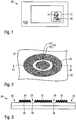
- FIG. 1 shows a schematic representation of a banknote 10, which is provided with a security element according to the invention in the form of a film patch 12.
- the invention is not limited to the transfer element shown in the illustration for banknotes, but can also be used, for example, in security threads, wide security strips or cover foils which are arranged above an opaque area, a window area or a through opening of any desired data carrier.
- the foil patch 12 shows a metallized, for the viewer out of the x-y plane of the security element Unewölbendes, three-dimensional relief motif 14, which may be formed for example in the form of a portrait, an architectural or technical motif or a nature motif.
- the relief motif 14 contains not only metallized subregions but also demetallized subregions which, on the one hand, have a creative function within the image motif, but on the other hand can also assume the information-carrying function and can, for example, represent a negative typeface.
- the demetallized subregions are conventionally produced by the imprint of wash ink and a washout step after the metallization, only relatively large-area subregions with the smallest dimension of 1 mm or a line thickness of 100 ⁇ m or more can be introduced.
- FIGS. 2 and 3 a detail 16 of the relief motif 14, wherein Fig. 2 a supervision and Fig. 3 a cross section along the line III-III of Fig. 2 represents.
- the detail could be a button, an epaulette or, for example, an eye (elsewhere in the subject).
- the detail 16 of the relief motif 14 contains a metallized relief region 20 with partial regions 22, 24, a large demetallized region 26 and a narrow, demetallized strip 28, which separates the two metallized partial regions 22, 24 of the relief region 20 from one another.
- the relief structure of the partial regions 22, 24 on a plurality of inclined, small micromirror 30, which reflect due to their metallization incident light efficiently in a predetermined direction. Due to their orientation, the micromirrors 30 give the viewer the impression of a predetermined three-dimensional relief motif 14, for example the portrait of the person Fig. 1 ,
- the demetallized strip 28 separating the two subregions 22, 24 is very delicate and, in the exemplary embodiment, has a width of only 50 ⁇ m.
- the demetallized flat area 38 is arranged in perfect register with the metallized relief areas 22, 24.
- conventional printing of wash paint does not produce such narrow demetallized structures.
- the method according to the invention is based on the surprising finding of the inventors that the toning film, which is unavoidable in terms of process technology, can be used and utilized in a simple and reliable manner to produce filigree, precisely matched demetallised structures 28 within metallized relief structures 22, 24.
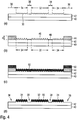
- FIG. 4 (a) An embossing lacquer layer 42 is applied to a carrier film 40 and the desired relief structure with the arrangement of micromirrors 30 is embossed into the embossing lacquer layer 42.
- the relief structure is provided in a relief area with two partial areas 32, 34 whose shape and size are precisely the shape and size of the areas to be metallized 22, 24 (FIG. Fig. 2 ) corresponds.
- the micromirrors 30 thereby form elevations and depressions in the embossing lacquer layer 42, which in the exemplary embodiment have a structure width of approximately 10 ⁇ m and, depending on the angle of inclination of the micromirrors 30, a structure height of up to approximately 8 ⁇ m.
- the two partial areas 32, 34 are separated from each other by a narrow flat area 38, in which there are no micromirrors or other elevations or depressions. Outside the subregions 32, 34, a large-area demetallization region 36 is provided in which likewise no metallization should be present in the finished security element 12.
- the large-area demetallization area 36 has a smallest dimension of more than 1 mm and can therefore be demetallized by the imprint of wash ink and a subsequent wash step in a conventional manner, this is not possible for the narrow flat area 38 because wash color is not so low line width still with the required accuracy relative to the height-structured portions 32, 34 can be applied.
- wash ink is printed by gravure printing only on the demetalization regions 36 and other large-area demetallization regions of the carrier 40, 42 and thereby deliberately exploited the normally unwanted toning.
- the inventors have surprisingly found that the in the nominally unprinted surface areas 32, 34, 38 unavoidable Tonungsfilm in the flat areas 38 and in the height-structured areas 32, 34 has different effects on the subsequent demetallization: During the thin Tonungsfilm the wash color in the narrow Flat areas 38 leads to a substantial or even complete Demetallmaschine finds in the height-structured areas 32, 34 despite the Tonung no demetallization instead.
- this phenomenon is currently understood as follows: With reference to Fig. 4 (b)
- the wash ink 44 is printed in the large-area demetallization regions 36 in a layer thickness d sufficient for a safer demetallization.
- a thin toning film 46, 48 is produced by the toning which is unavoidable in gravure printing.
- This thin toning film 48 now forms a substantially continuous thin wash-ink layer in the flat areas 38.
- the elevations and depressions of the micromirrors 30 act as small spacers for the color-guiding gravure cylinder, so that the latter only comes into contact with the tips of the micromirrors 30 comes and transfers only to this wash 46.
- the surface density of the transferred Tonungsfilms 46 can be influenced on the one hand by the shape of the surveys, on the other hand, but also by the properties of the wash and the process conditions during the printing process.
- the contact surface of the height-structured regions can be kept very small with the gravure cylinder by pointed elevations.
- the toning of the wash color can be influenced by the pigmentation of the wash color, the choice of the binder or by the electrostatics during the printing process.
- the carrier 40, 42 provided with wash ink 44, 46, 48 is provided in the usual manner over its entire area with a metal layer 50 which covers both the demetallization areas 36 and the flat areas 38 and the height-structured micromirror areas 32, 34, as in FIG Fig. 4 (c) shown.
- Simple metallizations made of Al, Cr, Cu and the like, as well as multi-layer structures with one or more metal layers may be considered as the metal layer 50.
- the metallized support is subjected to a washing-out step with a solvent, for example water, in which the washing color 44 with the metallization 50 in the demetallization regions 36 is completely or completely removed in the flat regions 38.
- a solvent for example water
- the metallization in the height-structured regions 32, 34 is retained and forms the desired metallized regions 22, 24, since the surface density and the cohesion of the wash-dye layer 46 are not there for demetallization suffice.
- the desired register-accurate filigree demetallization of the flat area 38 is also created.
- the toning can be deliberately increased to the extent that the demetallization in the flat area 38 is promoted, but without producing undesired demetallization in the height-structured regions 32, 34.
- demetallization in the flat area 38 is preferably complete, this is not absolutely necessary for many applications, since small metal residues hardly appear in the narrow flat areas 38 between the reflective areas 22, 24.
- the separating effect of the strips 28 already occurs when the metallization of the flat areas is largely, ie, for example, 70% or more removed.
Abstract
Die Erfindung betrifft ein Verfahren zum Herstellen eines Sicherheitselements mit einem metallisierten Reliefbereich (22, 24) und einem dazu gepasserten, schmalen, demetallisierten Flachbereich (28), bei dem
R) ein Träger (40, 42) so mit einer Reliefstruktur (14) mit Erhebungen und Vertiefungen (30) versehen wird, dass ein Reliefbereich (32, 34) und ein dazu gepasserter schmaler Flachbereich (38) ohne Erhebungen und Vertiefungen gebildet werden, wobei der Flachbereich (38) zumindest zwei Teilbereiche (32, 34) des Reliefbereichs voneinander trennt,
W) für den Träger (40, 42) im Reliefbereich (32, 34) und im Flachbereich (38) eine Waschfarbenschicht (46, 48) geringer Schichtdicke bereitgestellt und auf den Träger aufgebracht wird,
M) der mit Waschfarbe (44, 46, 48) versehene Träger (40, 42) zumindest im Reliefbereich (32, 34) und Flachbereich (38) metallisiert wird, und
A) der metallisierte Träger (40, 42, 50) einem Auswaschschritt mit einem Lösungsmittel unterworfen wird, bei dem in dem Flachbereich (38) die Waschfarbe (48) zusammen mit der darüberliegenden Metallisierung (50) entfernt und der Flachbereich (38) dadurch demetallisiert wird, während die Metallisierung (50) im Reliefbereich (32, 34) auf dem Träger (40, 42) verbleibt und den metallisierten Reliefbereich (22, 24) bildet.

R) a carrier (40, 42) is provided with a relief structure (14) with elevations and depressions (30) such that a relief region (32, 34) and a narrow flat region (38) adapted for this purpose are formed without elevations and depressions, wherein the flat region (38) separates at least two partial regions (32, 34) of the relief region from one another,
W) for the carrier (40, 42) in the relief region (32, 34) and in the flat region (38) a wash ink layer (46, 48) of small layer thickness is provided and applied to the carrier,
M) the carrier (40, 42) provided with wash ink (44, 46, 48) is metallized at least in the relief region (32, 34) and flat region (38), and
A) the metallized carrier (40, 42, 50) is subjected to a solvent washing step, wherein in the flat region (38) the wash ink (48) is removed together with the overlying metallization (50) and the flat region (38) is thereby demetallised while the metallization (50) remains in the relief region (32, 34) on the carrier (40, 42) and forms the metallized relief region (22, 24).
Description
Die Erfindung betrifft ein Verfahren zum Herstellen eines Sicherheitselements mit einem metallisierten Reliefbereich. Die Erfindung betrifft auch ein mit einem solchen Verfahren herstellbares Sicherheitselement zur Absicherung von Wertgegenständen.The invention relates to a method for producing a security element with a metallized relief region. The invention also relates to a security element which can be produced by means of such a method for securing valuables.
Datenträger, wie Wert- oder Ausweisdokumente, aber auch andere Wertgegenstände, wie etwa Markenartikel, werden zur Absicherung oft mit Sicherheitselementen versehen, die eine Überprüfung der Echtheit des Datenträgers gestatten und/oder als Schutz vor unerlaubter Reproduktion dienen. Die Sicherheitselemente können beispielsweise in Form metallisierter Folien in eine Banknote eingebettet werden oder über einem opaken Bereich, einem Fensterbereich oder einer durchgehenden Öffnung des Datenträgers angeordnet sein.Data carriers, such as valuables or identity documents, but also other valuables, such as branded articles, are often provided with security elements for the purpose of security, which permit verification of the authenticity of the data medium and / or serve as protection against unauthorized reproduction. The security elements can for example be embedded in a banknote in the form of metallized films or arranged over an opaque area, a window area or a continuous opening of the data carrier.
Die metallisierten Folien enthalten neben metallisierten Teilbereichen auch demetallisierte Teilbereiche, die der Darstellung eines gewünschten Motivs und/ oder einer zusätzlichen Echtheitsabsicherung des Datenträgers dienen. Erzeugt werden diese metallfreien Bereiche üblicherweise mit Hilfe eines Waschverfahrens, wie es beispielsweise in der Druckschrift
Die mit einem solchen Waschverfahren erreichbare Auflösung liegt allerdings nur bei einer Linienstärke von etwa 100 bis 200 µm. Für die Erzeugung feinerer Strukturen muss auf andere Verfahren, wie etwa eine Laserdemetallisation zurückgegriffen werden, was allerdings mit erheblichem zusätzlichem Zeit- und Kostenaufwand verbunden ist.However, the achievable with such a washing process resolution is only at a line thickness of about 100 to 200 microns. For the production of finer structures, other methods, such as laser demetallization, have to be resorted to, but this involves considerable additional time and expense.
Davon ausgehend liegt der Erfindung die Aufgabe zugrunde, die Nachteile des Standes der Technik zu vermeiden und insbesondere ein Verfahren zum Herstellen eines Sicherheitselements anzugeben, mit dem in einfacher Weise filigrane Demetallisierungsbereiche in einem metallisierten Reliefbereich erzeugt werden können.Based on this, the object of the invention is to avoid the disadvantages of the prior art and, in particular, to provide a method for producing a security element with which filigree demetallization areas in a metallized relief area can be produced in a simple manner.
Diese Aufgabe wird durch die Merkmale der unabhängigen Ansprüche gelöst. Weiterbildungen der Erfindung sind Gegenstand der abhängigen Ansprüche.This object is solved by the features of the independent claims. Further developments of the invention are the subject of the dependent claims.
Gemäß der Erfindung ist bei einem Verfahren zum Herstellen eines Sicherheitselements mit einem metallisierten Reliefbereich und einem dazu gepasserten, schmalen, demetallisierten Flachbereich vorgesehen, dass
- R) ein Träger so mit einer Reliefstruktur mit Erhebungen und Vertiefungen versehen wird, dass ein Reliefbereich und ein dazu gepasserter schmaler Flachbereich ohne Erhebungen und Vertiefungen gebildet werden, wobei der Flachbereich zumindest zwei Teilbereiche des Reliefbereichs voneinander trennt,
- W) für den Träger im Reliefbereich und im Flachbereich eine Waschfarbenschicht geringer Schichtdicke bereitgestellt und auf den Träger aufgebracht wird,
- M) der mit Waschfarbe versehene Träger zumindest im Reliefbereich und Flachbereich metallisiert wird, und
- A) der metallisierte Träger einem Auswaschschritt mit einem Lösungsmittel unterworfen wird, bei dem in dem Flachbereich die Waschfarbe zusammen mit der darüberliegenden Metallisierung entfernt und der Flachbereich dadurch demetallisiert wird, während die Metallisierung im Reliefbereich auf dem Träger verbleibt und den metallisierten Reliefbereich bildet.
- R) a carrier is provided with a relief structure with elevations and depressions, that a relief area and a narrow flat area adapted to be formed without elevations and depressions wherein the flat region separates at least two subregions of the relief region from one another,
- W) for the carrier in the relief area and in the flat area, a washing ink layer of small layer thickness is provided and applied to the carrier,
- M) the carrier provided with wash color is metallized at least in the relief area and flat area, and
- A) the metallized support is subjected to a washing-out step with a solvent, wherein in the flat area the wash color is removed together with the overlying metallization and the flat area is demetallized thereby, while the metallization in the relief area remains on the support and forms the metallized relief area.
Die Erfindung beruht dabei auf der überraschenden Erkenntnis, dass die im Schritt W) aufgebrachte dünne Waschfarbenschicht im Flachbereich und im Reliefbereich unterschiedliche Auswirkungen auf die nachfolgende Demetallisierung im Schritt A) hat. Während die dünne Waschfarbenschicht im schmalen Flachbereich zu einer Entfernung der Metallisierung führt, findet im Reliefbereich keine Demetallisierung statt. Eine dem gegenwärtigem Verständnis entsprechende Erklärung dieses Phänomens wird weiter unten vorgestellt.The invention is based on the surprising finding that the thin wash ink layer applied in step W) in the flat area and in the relief area has different effects on the subsequent demetallization in step A). While the thin washcoat layer in the narrow flat area leads to removal of the metallization, no demetallization takes place in the relief area. An explanation of this phenomenon, which corresponds to the current understanding, is presented below.
Da Relief- und Flachstrukturen mit großer Genauigkeit hergestellt werden können und die Metallisierung bzw. Demetallisierung durch das vorliegende Verfahren gepassert zu diesen Strukturen entstehen, können metallisierte und nicht-metallisierte Teilbereiche hochgenau aufeinander und auf die zugrundliegende Reliefstruktur ausgerichtet werden. Der Abstand zwischen dem Rand der Reliefstruktur und der Demetallisierung kann dabei kleiner als 10 µm, insbesondere kleiner als 3 µm oder sogar 2 µm gehalten werden. Mit herkömmlichen Verfahren ist eine solche Passergenauigkeit, allgemein und insbesondere für feine Demetallisierungs-Strukturen, nicht erreichbar. Da das herkömmliche, bereichsweise Aufdrucken von Waschfarbe in einem eigenständigen Druckschritt erfolgt, entstand eine Lagetoleranz von etwa 300 µm.Since relief and flat structures can be produced with great accuracy and the metallization or demetallization produced by the present process adapted to these structures, metallized and non-metallized portions are aligned with high precision on each other and on the underlying relief structure. The distance between the edge of the relief structure and the demetallization can be kept smaller than 10 .mu.m, in particular smaller than 3 .mu.m or even 2 .mu.m. With conventional methods, such registration accuracy is generally unattainable, especially for fine demetallization structures. Since the conventional, partial printing of wash ink takes place in an independent printing step, a positional tolerance of about 300 μm was created.
Der Reliefbereich wird im Rahmen dieser Beschreibung auch oft als höhenstrukturierter Bereich bezeichnet, da er als Strukturelemente Erhebungen und Vertiefungen aufweist. Es versteht sich, dass der Reliefbereich des Trägers neben den beiden genannten Teilbereichen auch weitere Teilbereiche aufweisen kann, die voneinander durch schmale Flachbereiche getrennt sind. Die nachfolgenden Ausführungen zu dem Flachbereich und den Teilbereichen des Reliefbereichs gelten vorzugsweise für alle auf dem Träger vorliegenden Flachbereiche und Relief-Teilbereiche.Within the scope of this description, the relief region is often also referred to as a height-structured region, since it has elevations and depressions as structural elements. It is understood that the relief region of the carrier may have, in addition to the two subregions mentioned, further subregions which are separated from one another by narrow flat regions. The following remarks on the flat area and the partial areas of the relief area preferably apply to all flat areas and relief partial areas present on the carrier.
Insbesondere wird für den Träger im Reliefbereich und im Flachbereich die Waschfarbenschicht geringer Schichtdicke auf einer Druckform bereitgestellt. Die Druckform wird mit dem Träger in Kontakt gebracht. Die Waschfarbenschicht wird durch den Kontakt mit den unterschiedlichen Bereichen, Reliefbereich und Flachbereich, unterschiedlich aufgebracht. Im Flachbereich des Trägers wird die Waschfarbenschicht geringer Schichtdicke durch den Kontakt mit der Druckform (vollflächig) aufgebracht. Im Reliefbereich des Trägers wird die Waschfarbenschicht geringer Schichtdicke durch den Kontakt mit der Druckform nur selektiv übertragen. Die Waschfarbenschicht wird auf der Druckform strukturfrei (unstrukturiert) bereitgestellt. Herkömmliche Beschränkungen bezüglich Strukturbreiten sind somit nicht relevant. Insbesondere wird die Waschfarbenschicht geringer Schichtdicke für den Träger im Reliefbereich und im Flachbereich unstrukturiert (und auf einer unstrukturierten Fläche der Druckform) bereitgestellt.In particular, for the carrier in the relief area and in the flat area, the wash-dye layer with a small layer thickness is provided on a printing form. The printing plate is brought into contact with the carrier. The wash ink layer is applied by the contact with the different areas, relief area and flat area, different. In the flat region of the support, the wash-dye layer with a small layer thickness is applied by contact with the printing forme (full area). In the relief region of the carrier, the wash ink layer of small layer thickness is only selectively transferred by the contact with the printing plate. The wash ink layer is provided on the printing plate without structure (unstructured). conventional Restrictions on structure widths are therefore not relevant. In particular, the washcoat layer with a low layer thickness is provided for the support in the relief area and in the flat area unstructured (and on an unstructured area of the printing form).
In einer vorteilhaften Ausgestaltung wird in Schritt W) die Waschfarbenschicht geringer Schichtdicke im Reliefbereich selektiv nur auf die Erhebungen der Reliefstruktur aufgebracht, bevorzugt auf die oberen 20%, insbesondere auf die oberen 10% der Erhebungen. In einer alternativen Gestaltung wird die Waschfarbenschicht geringer Schichtdicke im Reliefbereich selektiv nur in die Vertiefungen der Reliefstruktur eingebracht, bevorzugt in die unteren 20%, insbesondere in die unteren 10% der Vertiefungen.In an advantageous embodiment, in step W), the washcoat layer of low layer thickness in the relief area is selectively applied only to the elevations of the relief structure, preferably to the upper 20%, in particular to the upper 10% of the elevations. In an alternative embodiment, the washcoat layer of small layer thickness in the relief region is selectively introduced only into the depressions of the relief structure, preferably into the lower 20%, in particular into the lower 10% of the depressions.
In beiden Varianten können die Eigenschaften der Waschfarbe gezielt so gewählt werden, dass eine selektive Aufbringung bzw. Einbringung unterstützt wird. Eine hohe Viskosität der Waschfarbe fördert dabei ein selektives Aufbringen nur auf die Erhebungen, während eine niedrige Viskosität ein selektives Einbringen nur in die Vertiefungen der Reliefstruktur unterstützt.In both variants, the properties of the wash color can be selected specifically so that a selective application or introduction is supported. A high viscosity of the wash ink promotes a selective application only to the elevations, while a low viscosity assists a selective introduction only in the depressions of the relief structure.
Mit Vorteil wird in Schritt R) ein schmaler Flachbereich mit einer Breite unterhalb von 1000 µm gebildet wird, vorzugsweise ein Flachbereich mit einer Breite zwischen 10 µm und 1000 µm, besonders bevorzugt zwischen 10 µm bis 500 µm, und ganz besonders bevorzugt zwischen 10 µm bis 250 µm.Advantageously, a narrow flat area having a width of less than 1000 μm is formed in step R), preferably a flat area with a width of between 10 μm and 1000 μm, particularly preferably between 10 μm and 500 μm, and very particularly preferably between 10 μm and 250 μm.
Die Erhebungen und Vertiefungen der Reliefstruktur bilden vorteilhaft Strukturelemente mit einer Höhe von mehr als 0,5 µm, vorzugsweise von mehr als 1 µm oder von mehr als 2 µm, insbesondere von etwa 4 µm. Die Höhe der Strukturen liegt dabei - jeweils - bevorzugt unter 8 µm, also insbesondere zwischen 0,5 bis 8 µm, 2 bis 8 µm bzw. 3 bis 5 µm. Die laterale Ausdehnung der Strukturelemente ist vorzugsweise kleiner als 100 µm und liegt beispielsweise bei 10 µm bis 30 µm.The elevations and depressions of the relief structure advantageously form structural elements with a height of more than 0.5 μm, preferably more than 1 μm or more than 2 μm, in particular about 4 μm. The height of the structures is - in each case - preferably less than 8 microns, ie in particular between 0.5 to 8 microns, 2 to 8 microns and 3 to 5 microns. The lateral extent the structural elements is preferably less than 100 microns and is for example 10 microns to 30 microns.
Durch spitze Erhebungen kann eine besonders kleine Kontaktfläche des Reliefbereichs mit einer Druckform, wie etwa einem Tiefdruckzylinder, erhalten werden. Vorteilhaft weist die Reliefstruktur daher einen nichtsinusförmigen Querschnitt auf. Insbesondere ist die Reliefstruktur mit Vorteil mit spitzen Erhebungen, insbesondere in Form von Prismen oder von drei-, vier- oder mehrseitigen Pyramiden ausgebildet. Prismenförmige Strukturelemente sind dabei insbesondere so angeordnet, dass eine ihrer Kanten dachartig eine linienförmige Spitze ausbildet. Die geringe Schichtdicke der Waschfarbenschicht liegt bevorzugt unter 20%, insbesondere im Bereich von 1 bis 20%, vorzugsweise zwischen 1 bis 10%, der Reliefstrukturhöhe.By peaking a particularly small contact surface of the relief area can be obtained with a printing plate, such as a gravure cylinder. The relief structure therefore advantageously has a non-sinusoidal cross-section. In particular, the relief structure is advantageously formed with pointed elevations, in particular in the form of prisms or three, four or more sided pyramids. Prism-shaped structural elements are in particular arranged so that one of its edges roof-like forms a line-shaped tip. The small layer thickness of the wash ink layer is preferably below 20%, in particular in the range of 1 to 20%, preferably between 1 and 10%, of the relief structure height.
Bevorzugt ist die Reliefstruktur durch eine Prägestruktur gebildet, da sich durch Prägung die gewünschten Strukturen einfach und mit hoher Genauigkeit erzeugen lassen. Die Reliefstruktur kann insbesondere eine Mikrospiegelanordnung, ein Blazegitter mit einem sägezahnartigen Furchenprofil, eine Fresnellinsen-Anordnung, oder auch eine diffraktive Struktur, wie etwa ein Hologramm, ein holographisches Gitterbild oder eine hologrammähnliche Beugungsstruktur sein. Vorteilhaft wirkt die metallisierte Reliefstruktur als diffuser oder metallischer Reflektor, es liegt jedoch auch im Rahmen der Erfindung, dass die Reliefstruktur lediglich als Abstandhalters für die Druckform beim Aufdruckvorgang dient und die visuellen Reflexionseigenschaften des Sicherheitselements nicht oder kaum beeinflusst.Preferably, the relief structure is formed by an embossed structure, as can be produced by embossing the desired structures easily and with high accuracy. The relief structure may in particular be a micromirror arrangement, a blazed grating with a sawtooth-type furrow profile, a Fresnel lens arrangement, or else a diffractive structure, such as a hologram, a holographic grating image or a hologram-like diffraction structure. Advantageously, the metallized relief structure acts as a diffuse or metallic reflector, but it is also within the scope of the invention that the relief structure merely serves as a spacer for the printing plate during the printing process and does not or hardly influences the visual reflection properties of the security element.
Für Waschfarben sind jeweils geeignete Lösungsmittel verfügbar. In einer einfachen Ausgestaltung kann Wasser als Lösungsmittel verwendet werden.For washing colors, suitable solvents are available in each case. In a simple embodiment, water can be used as a solvent.
In einer gegenwärtig besonders vorteilhaften Ausgestaltung ist vorgesehen, dass die Waschfarbenschicht geringer Schichtdicke im Schritt W) als Tonung in einem Tiefdruckschritt auf den Reliefbereich und den Flachbereich aufgebracht wird. Weiter ist mit Vorteil vorgesehen, dass in dem Tiefdruckschritt gleichzeitig in einem Demetallisierungsbereich Waschfarbe mit normaler Schichtdicke aufgebracht wird, dass in Schritt M) auch der Demetallisierungsbereich metallisiert wird, und dass in Schritt A) in dem Demetallisierungsbereich die Waschfarbe normaler Schichtdicke zusammen mit der darüberliegenden Metallisierung entfernt und der Demetallisierungsbereich dadurch demetallisiert wird.In a presently particularly advantageous embodiment, it is provided that the wash ink layer with a small layer thickness is applied to the relief area and the flat area in step W) as toning in a gravure printing step. Furthermore, it is advantageously provided that in the deep-pressure step, a washcoat of normal thickness is simultaneously applied in a demetallization area, that in step M) the demetallization area is also metallized, and that in step A) in the demetallization area the washcoat of normal thickness together with the overlying metallization removed and demetallisiert the Demetallisierungsbereich thereby.
Eine "normale Schichtdicke" bezeichnet dabei eine Schichtdicke der Waschfarbe, bei der eine sicherere Demetallisierung in den großflächigen Demetallisierungsbereichen gewährleistet ist. Die "geringe Schichtdicke" ist vorzugsweise mindestens (5-mal oder) 10-mal kleiner als die normale Schichtdicke.A "normal layer thickness" refers to a layer thickness of the washing ink which ensures a safer demetallization in the large-area demetallization areas. The "small layer thickness" is preferably at least (5 times or) 10 times smaller than the normal layer thickness.
Die herkömmlich unerwünschte Tonung der Waschfarbe kann im Rahmen der Erfindung gezielt eingesetzt und auf einen Wert erhöht werden, bei dem die Demetallisierung im Flachbereich gefördert wird, eine unerwünschte Demetallisierung im Reliefbereich aber noch nicht auftritt. Die Tonung der Waschfarbe kann dabei durch mindestens einen der folgenden Parameter (bzw. Kombinationen hieraus) eingestellt sein: die Pigmentierung der Waschfarbe, die Wahl des Bindemittels , durch die Elektrostatik beim Druckvorgang (Ein- oder Ausschalten der elektrostatischen Druckhilfe ESA), die Einstellung des Rakel (wie Anstellwinkel), Art und Druck des Presseurs, Umfang des Druckzylinders und/oder der Atmosphäre des Druckzylinders beeinflusst werden.The conventionally undesirable Tonung the wash color can be used selectively in the context of the invention and increased to a value at which the Demetallisierung is promoted in the flat area, an undesirable Demetallisierung in the relief area but not yet occurs. The toning of the wash ink can be adjusted by at least one of the following parameters (or combinations thereof): the pigmentation of the wash color, the choice of binder, by the electrostatics during the printing process (switching on or off of the electrostatic pressure assist ESA), the setting of Squeegee (such as angle), type and pressure of the impression, the circumference of the impression cylinder and / or the atmosphere of the impression cylinder are affected.
Die Demetallisierung im Flachbereich muss nicht zwingend vollständig sein, da kleine Metallreste in den schmalen Flachbereichen zwischen den reflektierenden Relief-Teilbereichen kaum auffallen. In der Praxis haben sich Demetallisierungsgrade oberhalb von 70%, vorzugsweise oberhalb von 80% und insbesondere oberhalb von 90% bewährt.The demetallization in the flat area does not necessarily have to be complete, since small metal remnants in the narrow flat areas between the reflective relief partial areas are hardly noticeable. In practice, degrees of demetallization have proven to be above 70%, preferably above 80% and in particular above 90%.
Das Bindemittel der Waschfarbe ist mit Vorteil wasserlöslich und die verwendete Waschfarbe hat vorteilhaft einen besonders hohen Farbübertrag. Weiter ist der Tiefdruckzylinder in seinen flachen Bereichen zweckmäßig mit einer gewissen Rauigkeit versehen, insbesondere um den Lauf des Rakels zu optimieren.The binder of the washing ink is advantageously water-soluble and the washing ink used advantageously has a particularly high color transfer. Further, the gravure cylinder is expediently provided with a certain roughness in its flat areas, in particular in order to optimize the running of the doctor blade.
In einer anderen, ebenfalls vorteilhaften Ausgestaltung ist vorgesehen, dass die Waschfarbenschicht geringer Schichtdicke im Schritt W) als ultradünne Farbschicht in einem Flexodruckschritt auf den Reliefbereich und den Flachbereich aufgebracht wird. Dabei ist weiter mit Vorteil vorgesehen, dass in dem Flexodruckschritt gleichzeitig in einem Demetallisierungsbereich Waschfarbe mit normaler Schichtdicke aufgebracht wird, dass in Schritt M) auch der Demetallisierungsbereich metallisiert wird, und dass in Schritt A) in dem Demetallisierungsbereich die Waschfarbe normaler Schichtdicke zusammen mit der darüberliegenden Metallisierung entfernt und der Demetallisierungsbereich dadurch demetallisiert wird. Die obigen Ausführungen zur normalen bzw. geringen Schichtdicke der Waschfarbe und deren Eigenschaften gelten bei dieser Ausgestaltung entsprechend.In another embodiment, which is likewise advantageous, it is provided that the wash ink layer with a small layer thickness is applied to the relief area and the flat area in step W) as an ultrathin color layer in a flexographic printing step. In this case, it is further provided with advantage that wash ink of normal layer thickness is simultaneously applied in a demetallization region in step, the demetallization region is metallized in step M), and that in step A) in the demetallization region the wash color of normal layer thickness together with the overlying Metallization removed and the Demetallisierungsbereich is thereby demetallisiert. The above statements on the normal or low layer thickness of the wash color and their properties apply accordingly in this embodiment.
Neben den genannten Bereichen kann das Sicherheitselement auf dem Träger auch einen herkömmlichen, großflächig metallisierten Teilbereich enthalten, in dem keine Reliefstrukturen vorliegen.In addition to the above-mentioned areas, the security element on the support can also contain a conventional, large-area metallized subarea in which there are no relief structures.
Um ein Austrocknen der Waschfarbe auf der Rolle zu verhindern, wird die Waschfarbe vorteilhaft in einer Lösungsmittelatmosphäre aufgebracht.In order to prevent the washing ink from drying out on the roll, the washing ink is advantageously applied in a solvent atmosphere.
Die Metallisierung in Schritt M) ist vorteilhaft durch eine Einzelmetallschicht, vorzugsweise mit einer Dicke zwischen 5 nm und 100 nm, oder durch eine oder mehrere Einzelmetallschichten in einem Mehrschichtaufbau gebildet. Als Einzelmetallschicht kann beispielsweise eine Aluminium-, Chrom- oder Kupferschicht aufgebracht werden. Die Metallschicht und mögliche weitere Schichten des Mehrschichtaufbaus werden bevorzugt aufgedampft (mittels CVD- oder PVD-Verfahren). Mehrschichtaufbauten können beispielsweise in Form eines farbkippenden Dünnschichtelements mit einer metallischen Absorberschicht, einer dielektrischen Abstandsschicht und einer metallischen Reflektorschicht erzeugt werden. Mit der Metallschicht der Metallisierung können optional also zugleich auch Nicht-metallische Schichten entfernt werden.The metallization in step M) is advantageously formed by a single metal layer, preferably with a thickness between 5 nm and 100 nm, or by one or more individual metal layers in a multi-layer structure. As a single metal layer, for example, an aluminum, chromium or copper layer can be applied. The metal layer and possible further layers of the multilayer structure are preferably vapor-deposited (by means of CVD or PVD methods). Multilayer structures can be produced, for example, in the form of a color-shifting thin-film element with a metallic absorber layer, a dielectric spacer layer and a metallic reflector layer. With the metal layer of the metallization optionally also non-metallic layers can be removed at the same time.
Die Erfindung enthält auch ein Sicherheitselement zur Absicherung von Wertgegenständen, das mit einem Verfahren der genannten Art herstellbar ist. Das Sicherheitselement enthält einen Träger mit einer metallisierten Reliefstruktur mit Erhebungen und Vertiefungen und einen zu der Reliefstruktur gepasserten, schmalen, demetallisierten Flachbereich ohne Erhebungen und Vertiefungen. Der Flachbereich trennt zumindest zwei Teilbereiche des Reliefbereichs voneinander und weist eine Breite unterhalb von 1000 µm, bevorzugt eine Breite zwischen 10 µm und 500 µm, insbesondere zwischen 10 µm und 250 µm auf.The invention also includes a security element for securing valuables, which can be produced by a method of the type mentioned. The security element contains a carrier with a metallized relief structure with elevations and depressions and a narrow demetallised flat area without elevations and depressions which has been adapted to the relief structure. The flat region separates at least two partial regions of the relief region from one another and has a width of less than 1000 μm, preferably a width of between 10 μm and 500 μm, in particular between 10 μm and 250 μm.
Die Reliefstruktur besteht mit Vorteil aus Strukturelementen mit spitzen Erhebungen, insbesondere in Form von Prismen oder von drei-, vier- oder mehrseitigen Pyramiden. Die Erhebungen und Vertiefungen der Reliefstruktur bilden vorteilhaft Strukturelemente mit einer Höhe von mehr als 0,5 µm, vorzugsweise von mehr als 1 µm oder von mehr als 2 µm, insbesondere von etwa 4 µm. . Die Höhe der Strukturen liegt dabei - jeweils - bevorzugt unter 8 µm, also insbesondere zwischen 0,5 bis 8 µm, bevorzugt zwischen 2 bis 8 µm bzw. besonders bevorzugt zwischen 3 bis 5 µm. Die laterale Ausdehnung der Strukturelemente ist vorzugsweise kleiner als 100 µm und liegt beispielsweise bei 10 µm bis 30 µm. Im Übrigen gelten die weiteren, bei der Schilderung des Herstellungsverfahrens gemachten Ausführungen auch für das mit diesem Verfahren hergestellte Sicherheitselement.The relief structure advantageously consists of structural elements with pointed elevations, in particular in the form of prisms or of pyramids of three, four or more sides. The elevations and depressions of the relief structure form advantageous structural elements with a height of more than 0.5 microns, preferably more than 1 micron or more than 2 microns, in particular of about 4 microns. , The height of the structures is-in each case-preferably less than 8 μm, that is to say in particular between 0.5 and 8 μm, preferably between 2 and 8 μm or particularly preferably between 3 and 5 μm. The lateral extent of the structural elements is preferably less than 100 μm and, for example, 10 μm to 30 μm. Incidentally, the other statements made in the description of the production method also apply to the security element produced by this method.
Weitere Ausführungsbeispiele sowie Vorteile der Erfindung werden nachfolgend anhand der Figuren erläutert, bei deren Darstellung auf eine maßstabs- und proportionsgetreue Wiedergabe verzichtet wurde, um die Anschaulichkeit zu erhöhen.Further exemplary embodiments and advantages of the invention are explained below with reference to the figures, in the representation of which a representation true to scale and proportion has been dispensed with in order to increase the clarity.
Es zeigen:
- Fig. 1
- eine schematische Darstellung einer Banknote mit einem erfindungsgemäßen Sicherheitselement in Form eines Folienpatches mit einem Reliefmotiv,
- Fig. 2
- einen Detailausschnitt des Reliefmotivs der
Fig. 1 in Aufsicht, - Fig. 3
- einen Querschnitt des Detailausschnitts der
Fig. 2 entlang der Linie III-III, und - Fig. 4
- in (a) bis (d) jeweils den Detailausschnitt der
Figuren 2 und 3 bei Zwischenschritten des Herstellungsprozesses.
- Fig. 1
- a schematic representation of a banknote with a security element according to the invention in the form of a foil patch with a relief motif,
- Fig. 2
- a detail of the relief motif of
Fig. 1 in supervision, - Fig. 3
- a cross section of the detail of the
Fig. 2 along the line III-III, and - Fig. 4
- in (a) to (d) each detail of the
FIGS. 2 and 3 at intermediate steps of the manufacturing process.
Die Erfindung wird nun am Beispiel von Sicherheitselementen für Banknoten und andere Wertdokumente erläutert.
Der Folienpatch 12 zeigt ein metallisiertes, sich für den Betrachter aus der x-y-Ebene des Sicherheitselements herauswölbendes, dreidimensionales Reliefmotiv 14, das beispielsweise in Form eines Portraits, eines architektonischen oder technischen Motivs oder eines Naturmotivs ausgebildet sein kann. Das Reliefmotiv 14 enthält neben metallisierten Teilbereichen auch demetallisierte Teilbereiche, die einerseits gestalterische Funktion innerhalb des Bildmotivs haben, andererseits aber auch informationstragende Funktion übernehmen und beispielsweise eine Negativschrift darstellen können.The
Werden die demetallisierte Teilbereiche herkömmlich durch den Aufdruck von Waschfarbe und einen Auswaschschritt nach der Metallisierung erzeugt, können nur relativ großflächige Teilbereiche mit kleinsten Abmessung von 1 mm oder einer Linienstärke von 100µm oder mehr eingebracht werden.If the demetallized subregions are conventionally produced by the imprint of wash ink and a washout step after the metallization, only relatively large-area subregions with the smallest dimension of 1 mm or a line thickness of 100 μm or more can be introduced.
Zur näheren Erläuterung der erfindungsgemäßen Besonderheit zeigen
Wie am besten im Querschnitt der
Der die beiden Teilbereiche 22, 24 voneinander trennende demetallisierte Streifen 28 ist sehr filigran und weist im Ausführungsbeispiel eine Breite von nur 50 µm auf. Der Streifen 28 ist im Gegensatz zu den Teilbereichen 22, 24, in denen die geneigten Mikrospiegel 30 Erhebungen und Vertiefungen bilden, als Flachbereich 38 ohne Erhebungen und Vertiefungen ausgebildet.The
Trotz seiner geringen Breite ist der demetallisierte Flachbereich 38 in perfektem Passer zu den metallisierten Reliefbereichen 22, 24 angeordnet. Wie oben erläutert, lassen sich mit einem herkömmlichen Druck von Waschfarbe keine derart schmalen demetallisierten Strukturen erzeugen. Das erfindungsgemäße Verfahren beruht auf der überraschenden Erkenntnis der Erfinder, dass der im Tiefdruck prozesstechnisch unvermeidliche Tonungsfilm gezielt eingesetzt und genutzt werden kann, um in einfacher und zuverlässiger Weise filigrane, exakt gepasserte demetallisierte Strukturen 28 innerhalb von metallisierten Reliefstrukturen 22, 24 zu erzeugen.Despite its small width, the demetallized
Das erfindungsgemäße Prinzip wird nun mit Bezug auf
Mit Bezug zunächst auf
Die Mikrospiegel 30 bilden dabei Erhebungen und Vertiefungen in der Prägelackschicht 42, welche im Ausführungsbeispiel eine Strukturbreite von etwa 10 µm und, abhängig vom Neigungswinkel der Mikrospiegel 30, eine Strukturhöhe von bis zu etwa 8 µm aufweisen.The
Die beiden Teilbereiche 32, 34 sind voneinander durch einen schmalen Flachbereich 38 getrennt, in dem keine Mikrospiegel oder andere Erhebungen oder Vertiefungen vorliegen. Außerhalb der Teilbereiche 32, 34 ist ein großflächiger Demetallisierungsbereich 36 vorgesehen, in dem im fertigen Sicherheitselement 12 ebenfalls keine Metallisierung vorliegen soll.The two
Während der großflächige Demetallisierungsbereich 36 eine kleinste Abmessung von mehr als 1 mm aufweist und daher durch den Aufdruck von Waschfarbe und einen nachfolgenden Waschschritt in herkömmlicher Weise demetallisiert werden kann, ist dies für den schmalen Flachbereich 38 nicht möglich, da Waschfarbe weder mit einer so geringen Strichstärke noch mit der erforderlichen Genauigkeit relativ zu den höhenstrukturierten Teilbereichen 32, 34 aufgebracht werden kann.While the large-
Um dennoch die gewünschte hochgenaue Demetallisierung im Flachbereich 38 zu erreichen, wird Waschfarbe im Tiefdruckverfahren nur auf die Demetallisierungsbereiche 36 und andere großflächige Demetallisierungsbereiche des Trägers 40, 42 aufgedruckt und dabei gezielt die normalerweise unerwünschte Tonung ausgenutzt. Die Erfinder haben nämlich überraschend gefunden, dass der in den nominell unbedruckten Flächenbereichen 32, 34, 38 unvermeidliche Tonungsfilm in den Flachbereichen 38 und in den höhenstrukturierten Bereichen 32, 34 unterschiedliche Auswirkungen auf die spätere Demetallisierung hat: Während der dünne Tonungsfilm der Waschfarbe in den schmalen Flachbereichen 38 zu einer weitgehenden oder sogar vollständigen Demetallisierung führt, findet in den höhenstrukturierten Bereichen 32, 34 trotz der Tonung keine Demetallisierung statt.In order nevertheless to achieve the desired high-precision demetallization in the
Ohne an eine bestimmte Erklärung gebunden sein zu wollen wird dieses Phänomen gegenwärtig wie folgt verstanden: Mit Bezug auf
Dieser dünne Tonungsfilm 48 bildet nun in den Flachbereichen 38 eine im Wesentlichen durchgehende dünne Waschfarbenschicht. In den höhenstrukturierten Bereichen 32, 34 wirken dagegen die Erhebungen und Vertiefungen der Mikrospiegel 30 als kleine Abstandhalter zum farbführenden Tiefdruckzylinder, so dass dieser nur mit den Spitzen der Mikrospiegel 30 in Kontakt kommt und nur auf diese Waschfarbe 46 überträgt. In den höhenstrukturierten Bereichen 32, 34 entsteht dadurch ein nicht-zusammenhängender Tonungsfilm mit einer wesentlich geringeren Flächendichte, wie in
Anschließend wird der mit Waschfarbe 44, 46, 48 versehene Träger 40, 42 in üblicher Weise vollflächig mit einer Metallschicht 50 versehen, die sowohl die Demetallisierungsbereiche 36 als auch die Flachbereiche 38 und die höhenstrukturierten Mikrospiegel-Bereiche 32, 34 bedeckt, wie in
Mit Bezug auf
Da die normalerweise unerwünschte Tonung der Waschfarbe bei der erfindungsgemäßen Vorgehensweise vorteilhaft ist, kann die Tonung gezielt soweit erhöht werden, dass die Demetallisierung im Flachbereich 38 gefördert wird, ohne jedoch eine unerwünschte Demetallisierung in den höhenstrukturierten Bereichen 32, 34 zu erzeugen. Weiter ist die Demetallisierung im Flachbereich 38 zwar vorzugsweise vollständig, dies ist jedoch für viele Anwendungen nicht zwingend erforderlich, da kleine Metallreste in den schmalen Flachbereichen 38 zwischen den reflektierenden Bereichen 22, 24 kaum auffallen. Die trennende Wirkung der Streifen 28 tritt bereits dann auf, wenn die Metallisierung der Flachbereiche weitgehend, also beispielsweise zu 70% oder mehr, entfernt ist.Since the normally unwanted toning of the wash ink is advantageous in the procedure according to the invention, the toning can be deliberately increased to the extent that the demetallization in the
- 1010
- Banknotebill
- 1212
- Folienpatchfoil patch
- 1414
- Reliefmotivin relief
- 1616
- Detailausschnittcallout
- 2020
- metallisierter Reliefbereichmetallized relief area
- 22, 2422, 24
- Teilbereichesubregions
- 2626
- großflächiger demetallisierter Bereichlarge area demetallised area
- 2828
- schmaler demetallisierter Streifennarrow demetallised strip
- 3030
- Mikrospiegelmicromirror
- 32, 3432, 34
- Teilbereiche des ReliefbereichsSubareas of the relief area
- 3636
- großflächiger Demetallisierungsbereichlarge-area demetalization area
- 3838
- Flachbereichflat area
- 4040
- Trägerfoliesupport film
- 4242
- PrägelackschichtEmbossing lacquer layer
- 4444
- Waschfarbewashable ink
- 46, 4846, 48
- TonungsfilmTonungsfilm
- 5050
- Metallschichtmetal layer
Claims (15)
Applications Claiming Priority (1)
| Application Number | Priority Date | Filing Date | Title |
|---|---|---|---|
| DE102017004784.7A DE102017004784A1 (en) | 2017-05-18 | 2017-05-18 | Method for producing a security element with a metallized relief area and associated security element |
Publications (2)
| Publication Number | Publication Date |
|---|---|
| EP3403844A1 true EP3403844A1 (en) | 2018-11-21 |
| EP3403844B1 EP3403844B1 (en) | 2021-08-11 |
Family
ID=62167088
Family Applications (1)
| Application Number | Title | Priority Date | Filing Date |
|---|---|---|---|
| EP18000456.6A Active EP3403844B1 (en) | 2017-05-18 | 2018-05-14 | Method for producing a security element having a metallized relief area |
Country Status (2)
| Country | Link |
|---|---|
| EP (1) | EP3403844B1 (en) |
| DE (1) | DE102017004784A1 (en) |
Cited By (1)
| Publication number | Priority date | Publication date | Assignee | Title |
|---|---|---|---|---|
| WO2020216466A1 (en) * | 2019-04-26 | 2020-10-29 | Giesecke+Devrient Currency Technology Gmbh | Method for producing a security element, and security element |
Citations (4)
| Publication number | Priority date | Publication date | Assignee | Title |
|---|---|---|---|---|
| EP1972462A2 (en) * | 2007-01-05 | 2008-09-24 | Giesecke & Devrient GmbH | Method for producing security foils |
| WO2009083146A2 (en) * | 2007-12-21 | 2009-07-09 | Giesecke & Devrient Gmbh | Method for producing a microstructure |
| WO2009100869A2 (en) * | 2008-02-12 | 2009-08-20 | Giesecke & Devrient Gmbh | Security element and method for producing the same |
| WO2017028950A1 (en) * | 2015-08-17 | 2017-02-23 | Giesecke & Devrient Gmbh | Security element, method for producing same, and data carrier equipped with the security element |
Family Cites Families (5)
| Publication number | Priority date | Publication date | Assignee | Title |
|---|---|---|---|---|
| ATE131115T1 (en) * | 1991-10-14 | 1995-12-15 | Landis & Gyr Tech Innovat | SAFETY ELEMENT. |
| DE19739193B4 (en) | 1997-09-08 | 2006-08-03 | Giesecke & Devrient Gmbh | Method for producing security films for securities |
| DE102005034671A1 (en) * | 2005-07-25 | 2007-02-01 | Giesecke & Devrient Gmbh | Security element and method for its production |
| DE102006037431A1 (en) * | 2006-08-09 | 2008-04-17 | Ovd Kinegram Ag | Production of multi-layer bodies useful in element for security- and value document such as banknotes and credit cards, by forming a relief structure in an area of replication layer and applying a layer on carrier and/or replication layer |
| DE102015106800B4 (en) * | 2015-04-30 | 2021-12-30 | Leonhard Kurz Stiftung & Co. Kg | Method for producing a multilayer body |
-
2017
- 2017-05-18 DE DE102017004784.7A patent/DE102017004784A1/en not_active Withdrawn
-
2018
- 2018-05-14 EP EP18000456.6A patent/EP3403844B1/en active Active
Patent Citations (4)
| Publication number | Priority date | Publication date | Assignee | Title |
|---|---|---|---|---|
| EP1972462A2 (en) * | 2007-01-05 | 2008-09-24 | Giesecke & Devrient GmbH | Method for producing security foils |
| WO2009083146A2 (en) * | 2007-12-21 | 2009-07-09 | Giesecke & Devrient Gmbh | Method for producing a microstructure |
| WO2009100869A2 (en) * | 2008-02-12 | 2009-08-20 | Giesecke & Devrient Gmbh | Security element and method for producing the same |
| WO2017028950A1 (en) * | 2015-08-17 | 2017-02-23 | Giesecke & Devrient Gmbh | Security element, method for producing same, and data carrier equipped with the security element |
Cited By (1)
| Publication number | Priority date | Publication date | Assignee | Title |
|---|---|---|---|---|
| WO2020216466A1 (en) * | 2019-04-26 | 2020-10-29 | Giesecke+Devrient Currency Technology Gmbh | Method for producing a security element, and security element |
Also Published As
| Publication number | Publication date |
|---|---|
| DE102017004784A1 (en) | 2018-11-22 |
| EP3403844B1 (en) | 2021-08-11 |
Similar Documents
| Publication | Publication Date | Title |
|---|---|---|
| EP3820714B1 (en) | Optically variable security element having reflective surface region | |
| EP2953798B1 (en) | Optically variable surface pattern | |
| EP1786632B1 (en) | Metallisied security element | |
| EP2242657B1 (en) | Security element and method for producing the same | |
| EP2459387B1 (en) | Security element for an article to be protected and article to be protected with such a security element | |
| EP3260302B1 (en) | Optically variable security element | |
| EP3386771A1 (en) | Security element having a lenticular image | |
| EP3188916B1 (en) | Optical variable security element | |
| EP2708371B1 (en) | Visually variable security element with additional visual reflection/transmission effect | |
| EP3245073A1 (en) | Multilayer body and method for producing same | |
| EP3302995B1 (en) | Visually variable security element | |
| DE102014018551A1 (en) | value document | |
| EP4112326B1 (en) | Security substrate and valuable document produced therefrom | |
| EP3606765B1 (en) | Security element with relief structure and method for the production thereof | |
| EP3828002B1 (en) | Value document | |
| EP2448766B1 (en) | Security element, and method for the production thereof | |
| DE102013005938A1 (en) | Security thread or window element for a valuable article and manufacturing method therefor | |
| EP3403844B1 (en) | Method for producing a security element having a metallized relief area | |
| EP3793838B1 (en) | Security element having a surface region that is metallised in regions, production method and stamping tool | |
| DE102019005551A1 (en) | Manufacturing process for a security paper and thus obtainable security paper | |
| EP3606766B1 (en) | Security element and method for the production thereof | |
| EP3501841A1 (en) | Film security element and method of manufacturing same | |
| EP4219185A1 (en) | Film, film strip, valuable document and relative production method |
Legal Events
| Date | Code | Title | Description |
|---|---|---|---|
| PUAI | Public reference made under article 153(3) epc to a published international application that has entered the european phase |
Free format text: ORIGINAL CODE: 0009012 |
|
| STAA | Information on the status of an ep patent application or granted ep patent |
Free format text: STATUS: THE APPLICATION HAS BEEN PUBLISHED |
|
| AK | Designated contracting states |
Kind code of ref document: A1 Designated state(s): AL AT BE BG CH CY CZ DE DK EE ES FI FR GB GR HR HU IE IS IT LI LT LU LV MC MK MT NL NO PL PT RO RS SE SI SK SM TR |
|
| AX | Request for extension of the european patent |
Extension state: BA ME |
|
| STAA | Information on the status of an ep patent application or granted ep patent |
Free format text: STATUS: REQUEST FOR EXAMINATION WAS MADE |
|
| 17P | Request for examination filed |
Effective date: 20190521 |
|
| RBV | Designated contracting states (corrected) |
Designated state(s): AL AT BE BG CH CY CZ DE DK EE ES FI FR GB GR HR HU IE IS IT LI LT LU LV MC MK MT NL NO PL PT RO RS SE SI SK SM TR |
|
| GRAP | Despatch of communication of intention to grant a patent |
Free format text: ORIGINAL CODE: EPIDOSNIGR1 |
|
| STAA | Information on the status of an ep patent application or granted ep patent |
Free format text: STATUS: GRANT OF PATENT IS INTENDED |
|
| INTG | Intention to grant announced |
Effective date: 20210316 |
|
| GRAS | Grant fee paid |
Free format text: ORIGINAL CODE: EPIDOSNIGR3 |
|
| GRAA | (expected) grant |
Free format text: ORIGINAL CODE: 0009210 |
|
| STAA | Information on the status of an ep patent application or granted ep patent |
Free format text: STATUS: THE PATENT HAS BEEN GRANTED |
|
| AK | Designated contracting states |
Kind code of ref document: B1 Designated state(s): AL AT BE BG CH CY CZ DE DK EE ES FI FR GB GR HR HU IE IS IT LI LT LU LV MC MK MT NL NO PL PT RO RS SE SI SK SM TR |
|
| REG | Reference to a national code |
Ref country code: CH Ref legal event code: EP |
|
| REG | Reference to a national code |
Ref country code: DE Ref legal event code: R096 Ref document number: 502018006476 Country of ref document: DE |
|
| REG | Reference to a national code |
Ref country code: IE Ref legal event code: FG4D Free format text: LANGUAGE OF EP DOCUMENT: GERMAN Ref country code: AT Ref legal event code: REF Ref document number: 1419011 Country of ref document: AT Kind code of ref document: T Effective date: 20210915 |
|
| REG | Reference to a national code |
Ref country code: LT Ref legal event code: MG9D |
|
| REG | Reference to a national code |
Ref country code: NL Ref legal event code: MP Effective date: 20210811 |
|
| PG25 | Lapsed in a contracting state [announced via postgrant information from national office to epo] |
Ref country code: FI Free format text: LAPSE BECAUSE OF FAILURE TO SUBMIT A TRANSLATION OF THE DESCRIPTION OR TO PAY THE FEE WITHIN THE PRESCRIBED TIME-LIMIT Effective date: 20210811 Ref country code: ES Free format text: LAPSE BECAUSE OF FAILURE TO SUBMIT A TRANSLATION OF THE DESCRIPTION OR TO PAY THE FEE WITHIN THE PRESCRIBED TIME-LIMIT Effective date: 20210811 Ref country code: HR Free format text: LAPSE BECAUSE OF FAILURE TO SUBMIT A TRANSLATION OF THE DESCRIPTION OR TO PAY THE FEE WITHIN THE PRESCRIBED TIME-LIMIT Effective date: 20210811 Ref country code: RS Free format text: LAPSE BECAUSE OF FAILURE TO SUBMIT A TRANSLATION OF THE DESCRIPTION OR TO PAY THE FEE WITHIN THE PRESCRIBED TIME-LIMIT Effective date: 20210811 Ref country code: SE Free format text: LAPSE BECAUSE OF FAILURE TO SUBMIT A TRANSLATION OF THE DESCRIPTION OR TO PAY THE FEE WITHIN THE PRESCRIBED TIME-LIMIT Effective date: 20210811 Ref country code: PT Free format text: LAPSE BECAUSE OF FAILURE TO SUBMIT A TRANSLATION OF THE DESCRIPTION OR TO PAY THE FEE WITHIN THE PRESCRIBED TIME-LIMIT Effective date: 20211213 Ref country code: NO Free format text: LAPSE BECAUSE OF FAILURE TO SUBMIT A TRANSLATION OF THE DESCRIPTION OR TO PAY THE FEE WITHIN THE PRESCRIBED TIME-LIMIT Effective date: 20211111 Ref country code: LT Free format text: LAPSE BECAUSE OF FAILURE TO SUBMIT A TRANSLATION OF THE DESCRIPTION OR TO PAY THE FEE WITHIN THE PRESCRIBED TIME-LIMIT Effective date: 20210811 Ref country code: BG Free format text: LAPSE BECAUSE OF FAILURE TO SUBMIT A TRANSLATION OF THE DESCRIPTION OR TO PAY THE FEE WITHIN THE PRESCRIBED TIME-LIMIT Effective date: 20211111 |
|
| PG25 | Lapsed in a contracting state [announced via postgrant information from national office to epo] |
Ref country code: PL Free format text: LAPSE BECAUSE OF FAILURE TO SUBMIT A TRANSLATION OF THE DESCRIPTION OR TO PAY THE FEE WITHIN THE PRESCRIBED TIME-LIMIT Effective date: 20210811 Ref country code: LV Free format text: LAPSE BECAUSE OF FAILURE TO SUBMIT A TRANSLATION OF THE DESCRIPTION OR TO PAY THE FEE WITHIN THE PRESCRIBED TIME-LIMIT Effective date: 20210811 Ref country code: GR Free format text: LAPSE BECAUSE OF FAILURE TO SUBMIT A TRANSLATION OF THE DESCRIPTION OR TO PAY THE FEE WITHIN THE PRESCRIBED TIME-LIMIT Effective date: 20211112 |
|
| PG25 | Lapsed in a contracting state [announced via postgrant information from national office to epo] |
Ref country code: NL Free format text: LAPSE BECAUSE OF FAILURE TO SUBMIT A TRANSLATION OF THE DESCRIPTION OR TO PAY THE FEE WITHIN THE PRESCRIBED TIME-LIMIT Effective date: 20210811 |
|
| PG25 | Lapsed in a contracting state [announced via postgrant information from national office to epo] |
Ref country code: DK Free format text: LAPSE BECAUSE OF FAILURE TO SUBMIT A TRANSLATION OF THE DESCRIPTION OR TO PAY THE FEE WITHIN THE PRESCRIBED TIME-LIMIT Effective date: 20210811 |
|
| REG | Reference to a national code |
Ref country code: DE Ref legal event code: R097 Ref document number: 502018006476 Country of ref document: DE |
|
| PG25 | Lapsed in a contracting state [announced via postgrant information from national office to epo] |
Ref country code: SM Free format text: LAPSE BECAUSE OF FAILURE TO SUBMIT A TRANSLATION OF THE DESCRIPTION OR TO PAY THE FEE WITHIN THE PRESCRIBED TIME-LIMIT Effective date: 20210811 Ref country code: SK Free format text: LAPSE BECAUSE OF FAILURE TO SUBMIT A TRANSLATION OF THE DESCRIPTION OR TO PAY THE FEE WITHIN THE PRESCRIBED TIME-LIMIT Effective date: 20210811 Ref country code: RO Free format text: LAPSE BECAUSE OF FAILURE TO SUBMIT A TRANSLATION OF THE DESCRIPTION OR TO PAY THE FEE WITHIN THE PRESCRIBED TIME-LIMIT Effective date: 20210811 Ref country code: EE Free format text: LAPSE BECAUSE OF FAILURE TO SUBMIT A TRANSLATION OF THE DESCRIPTION OR TO PAY THE FEE WITHIN THE PRESCRIBED TIME-LIMIT Effective date: 20210811 Ref country code: CZ Free format text: LAPSE BECAUSE OF FAILURE TO SUBMIT A TRANSLATION OF THE DESCRIPTION OR TO PAY THE FEE WITHIN THE PRESCRIBED TIME-LIMIT Effective date: 20210811 Ref country code: AL Free format text: LAPSE BECAUSE OF FAILURE TO SUBMIT A TRANSLATION OF THE DESCRIPTION OR TO PAY THE FEE WITHIN THE PRESCRIBED TIME-LIMIT Effective date: 20210811 |
|
| PLBE | No opposition filed within time limit |
Free format text: ORIGINAL CODE: 0009261 |
|
| STAA | Information on the status of an ep patent application or granted ep patent |
Free format text: STATUS: NO OPPOSITION FILED WITHIN TIME LIMIT |
|
| 26N | No opposition filed |
Effective date: 20220512 |
|
| PG25 | Lapsed in a contracting state [announced via postgrant information from national office to epo] |
Ref country code: IT Free format text: LAPSE BECAUSE OF FAILURE TO SUBMIT A TRANSLATION OF THE DESCRIPTION OR TO PAY THE FEE WITHIN THE PRESCRIBED TIME-LIMIT Effective date: 20210811 |
|
| PG25 | Lapsed in a contracting state [announced via postgrant information from national office to epo] |
Ref country code: SI Free format text: LAPSE BECAUSE OF FAILURE TO SUBMIT A TRANSLATION OF THE DESCRIPTION OR TO PAY THE FEE WITHIN THE PRESCRIBED TIME-LIMIT Effective date: 20210811 |
|
| REG | Reference to a national code |
Ref country code: CH Ref legal event code: PL |
|
| REG | Reference to a national code |
Ref country code: BE Ref legal event code: MM Effective date: 20220531 |
|
| PG25 | Lapsed in a contracting state [announced via postgrant information from national office to epo] |
Ref country code: MC Free format text: LAPSE BECAUSE OF FAILURE TO SUBMIT A TRANSLATION OF THE DESCRIPTION OR TO PAY THE FEE WITHIN THE PRESCRIBED TIME-LIMIT Effective date: 20210811 Ref country code: LU Free format text: LAPSE BECAUSE OF NON-PAYMENT OF DUE FEES Effective date: 20220514 Ref country code: LI Free format text: LAPSE BECAUSE OF NON-PAYMENT OF DUE FEES Effective date: 20220531 Ref country code: CH Free format text: LAPSE BECAUSE OF NON-PAYMENT OF DUE FEES Effective date: 20220531 |
|
| PG25 | Lapsed in a contracting state [announced via postgrant information from national office to epo] |
Ref country code: IE Free format text: LAPSE BECAUSE OF NON-PAYMENT OF DUE FEES Effective date: 20220514 |
|
| PG25 | Lapsed in a contracting state [announced via postgrant information from national office to epo] |
Ref country code: BE Free format text: LAPSE BECAUSE OF NON-PAYMENT OF DUE FEES Effective date: 20220531 |
|
| P01 | Opt-out of the competence of the unified patent court (upc) registered |
Effective date: 20230520 |
|
| PGFP | Annual fee paid to national office [announced via postgrant information from national office to epo] |
Ref country code: FR Payment date: 20230517 Year of fee payment: 6 Ref country code: DE Payment date: 20230531 Year of fee payment: 6 |
|
| PGFP | Annual fee paid to national office [announced via postgrant information from national office to epo] |
Ref country code: AT Payment date: 20230516 Year of fee payment: 6 |
|
| PGFP | Annual fee paid to national office [announced via postgrant information from national office to epo] |
Ref country code: GB Payment date: 20230522 Year of fee payment: 6 |
|
| PG25 | Lapsed in a contracting state [announced via postgrant information from national office to epo] |
Ref country code: HU Free format text: LAPSE BECAUSE OF FAILURE TO SUBMIT A TRANSLATION OF THE DESCRIPTION OR TO PAY THE FEE WITHIN THE PRESCRIBED TIME-LIMIT; INVALID AB INITIO Effective date: 20180514 |