EP3403764B1 - Method of repairing a workpiece and masking fixture - Google Patents
Method of repairing a workpiece and masking fixture Download PDFInfo
- Publication number
- EP3403764B1 EP3403764B1 EP18171489.0A EP18171489A EP3403764B1 EP 3403764 B1 EP3403764 B1 EP 3403764B1 EP 18171489 A EP18171489 A EP 18171489A EP 3403764 B1 EP3403764 B1 EP 3403764B1
- Authority
- EP
- European Patent Office
- Prior art keywords
- workpiece
- masking fixture
- base wall
- purge flow
- masking
- Prior art date
- Legal status (The legal status is an assumption and is not a legal conclusion. Google has not performed a legal analysis and makes no representation as to the accuracy of the status listed.)
- Active
Links
- 230000000873 masking effect Effects 0.000 title claims description 127
- 238000000034 method Methods 0.000 title claims description 31
- 238000010926 purge Methods 0.000 claims description 44
- 239000012530 fluid Substances 0.000 claims description 30
- 230000002093 peripheral effect Effects 0.000 claims description 27
- 238000007789 sealing Methods 0.000 claims description 16
- 230000000295 complement effect Effects 0.000 claims description 6
- 238000004891 communication Methods 0.000 claims description 5
- 230000008439 repair process Effects 0.000 claims description 3
- 238000001816 cooling Methods 0.000 description 9
- 238000005270 abrasive blasting Methods 0.000 description 6
- 230000006835 compression Effects 0.000 description 3
- 238000007906 compression Methods 0.000 description 3
- 238000005461 lubrication Methods 0.000 description 2
- 239000004576 sand Substances 0.000 description 2
- 238000011144 upstream manufacturing Methods 0.000 description 2
- 230000002939 deleterious effect Effects 0.000 description 1
- 230000001771 impaired effect Effects 0.000 description 1
- 238000009434 installation Methods 0.000 description 1
- 230000001788 irregular Effects 0.000 description 1
- 238000005304 joining Methods 0.000 description 1
- 230000013011 mating Effects 0.000 description 1
- 238000012986 modification Methods 0.000 description 1
- 230000004048 modification Effects 0.000 description 1
- 230000037361 pathway Effects 0.000 description 1
- 238000005488 sandblasting Methods 0.000 description 1
- 238000009423 ventilation Methods 0.000 description 1
Images


Classifications
-
- B—PERFORMING OPERATIONS; TRANSPORTING
- B24—GRINDING; POLISHING
- B24C—ABRASIVE OR RELATED BLASTING WITH PARTICULATE MATERIAL
- B24C9/00—Appurtenances of abrasive blasting machines or devices, e.g. working chambers, arrangements for handling used abrasive material
-
- B—PERFORMING OPERATIONS; TRANSPORTING
- B23—MACHINE TOOLS; METAL-WORKING NOT OTHERWISE PROVIDED FOR
- B23P—METAL-WORKING NOT OTHERWISE PROVIDED FOR; COMBINED OPERATIONS; UNIVERSAL MACHINE TOOLS
- B23P6/00—Restoring or reconditioning objects
- B23P6/002—Repairing turbine components, e.g. moving or stationary blades, rotors
-
- B—PERFORMING OPERATIONS; TRANSPORTING
- B24—GRINDING; POLISHING
- B24B—MACHINES, DEVICES, OR PROCESSES FOR GRINDING OR POLISHING; DRESSING OR CONDITIONING OF ABRADING SURFACES; FEEDING OF GRINDING, POLISHING, OR LAPPING AGENTS
- B24B31/00—Machines or devices designed for polishing or abrading surfaces on work by means of tumbling apparatus or other apparatus in which the work and/or the abrasive material is loose; Accessories therefor
- B24B31/12—Accessories; Protective equipment or safety devices; Installations for exhaustion of dust or for sound absorption specially adapted for machines covered by group B24B31/00
-
- B—PERFORMING OPERATIONS; TRANSPORTING
- B24—GRINDING; POLISHING
- B24C—ABRASIVE OR RELATED BLASTING WITH PARTICULATE MATERIAL
- B24C1/00—Methods for use of abrasive blasting for producing particular effects; Use of auxiliary equipment in connection with such methods
- B24C1/04—Methods for use of abrasive blasting for producing particular effects; Use of auxiliary equipment in connection with such methods for treating only selected parts of a surface, e.g. for carving stone or glass
-
- B—PERFORMING OPERATIONS; TRANSPORTING
- B24—GRINDING; POLISHING
- B24C—ABRASIVE OR RELATED BLASTING WITH PARTICULATE MATERIAL
- B24C3/00—Abrasive blasting machines or devices; Plants
- B24C3/02—Abrasive blasting machines or devices; Plants characterised by the arrangement of the component assemblies with respect to each other
- B24C3/06—Abrasive blasting machines or devices; Plants characterised by the arrangement of the component assemblies with respect to each other movable; portable
- B24C3/065—Abrasive blasting machines or devices; Plants characterised by the arrangement of the component assemblies with respect to each other movable; portable with suction means for the abrasive and the waste material
-
- B—PERFORMING OPERATIONS; TRANSPORTING
- B24—GRINDING; POLISHING
- B24C—ABRASIVE OR RELATED BLASTING WITH PARTICULATE MATERIAL
- B24C3/00—Abrasive blasting machines or devices; Plants
- B24C3/32—Abrasive blasting machines or devices; Plants designed for abrasive blasting of particular work, e.g. the internal surfaces of cylinder blocks
-
- B—PERFORMING OPERATIONS; TRANSPORTING
- B24—GRINDING; POLISHING
- B24C—ABRASIVE OR RELATED BLASTING WITH PARTICULATE MATERIAL
- B24C9/00—Appurtenances of abrasive blasting machines or devices, e.g. working chambers, arrangements for handling used abrasive material
- B24C9/003—Removing abrasive powder out of the blasting machine
-
- F—MECHANICAL ENGINEERING; LIGHTING; HEATING; WEAPONS; BLASTING
- F01—MACHINES OR ENGINES IN GENERAL; ENGINE PLANTS IN GENERAL; STEAM ENGINES
- F01D—NON-POSITIVE DISPLACEMENT MACHINES OR ENGINES, e.g. STEAM TURBINES
- F01D25/00—Component parts, details, or accessories, not provided for in, or of interest apart from, other groups
- F01D25/002—Cleaning of turbomachines
-
- F—MECHANICAL ENGINEERING; LIGHTING; HEATING; WEAPONS; BLASTING
- F01—MACHINES OR ENGINES IN GENERAL; ENGINE PLANTS IN GENERAL; STEAM ENGINES
- F01D—NON-POSITIVE DISPLACEMENT MACHINES OR ENGINES, e.g. STEAM TURBINES
- F01D5/00—Blades; Blade-carrying members; Heating, heat-insulating, cooling or antivibration means on the blades or the members
- F01D5/005—Repairing methods or devices
-
- B—PERFORMING OPERATIONS; TRANSPORTING
- B23—MACHINE TOOLS; METAL-WORKING NOT OTHERWISE PROVIDED FOR
- B23P—METAL-WORKING NOT OTHERWISE PROVIDED FOR; COMBINED OPERATIONS; UNIVERSAL MACHINE TOOLS
- B23P2700/00—Indexing scheme relating to the articles being treated, e.g. manufactured, repaired, assembled, connected or other operations covered in the subgroups
- B23P2700/06—Cooling passages of turbine components, e.g. unblocking or preventing blocking of cooling passages of turbine components
-
- F—MECHANICAL ENGINEERING; LIGHTING; HEATING; WEAPONS; BLASTING
- F01—MACHINES OR ENGINES IN GENERAL; ENGINE PLANTS IN GENERAL; STEAM ENGINES
- F01D—NON-POSITIVE DISPLACEMENT MACHINES OR ENGINES, e.g. STEAM TURBINES
- F01D25/00—Component parts, details, or accessories, not provided for in, or of interest apart from, other groups
- F01D25/28—Supporting or mounting arrangements, e.g. for turbine casing
- F01D25/285—Temporary support structures, e.g. for testing, assembling, installing, repairing; Assembly methods using such structures
-
- F—MECHANICAL ENGINEERING; LIGHTING; HEATING; WEAPONS; BLASTING
- F01—MACHINES OR ENGINES IN GENERAL; ENGINE PLANTS IN GENERAL; STEAM ENGINES
- F01D—NON-POSITIVE DISPLACEMENT MACHINES OR ENGINES, e.g. STEAM TURBINES
- F01D5/00—Blades; Blade-carrying members; Heating, heat-insulating, cooling or antivibration means on the blades or the members
- F01D5/12—Blades
- F01D5/14—Form or construction
- F01D5/18—Hollow blades, i.e. blades with cooling or heating channels or cavities; Heating, heat-insulating or cooling means on blades
- F01D5/186—Film cooling
-
- F—MECHANICAL ENGINEERING; LIGHTING; HEATING; WEAPONS; BLASTING
- F01—MACHINES OR ENGINES IN GENERAL; ENGINE PLANTS IN GENERAL; STEAM ENGINES
- F01D—NON-POSITIVE DISPLACEMENT MACHINES OR ENGINES, e.g. STEAM TURBINES
- F01D9/00—Stators
- F01D9/06—Fluid supply conduits to nozzles or the like
- F01D9/065—Fluid supply or removal conduits traversing the working fluid flow, e.g. for lubrication-, cooling-, or sealing fluids
-
- F—MECHANICAL ENGINEERING; LIGHTING; HEATING; WEAPONS; BLASTING
- F05—INDEXING SCHEMES RELATING TO ENGINES OR PUMPS IN VARIOUS SUBCLASSES OF CLASSES F01-F04
- F05D—INDEXING SCHEME FOR ASPECTS RELATING TO NON-POSITIVE-DISPLACEMENT MACHINES OR ENGINES, GAS-TURBINES OR JET-PROPULSION PLANTS
- F05D2220/00—Application
- F05D2220/30—Application in turbines
-
- F—MECHANICAL ENGINEERING; LIGHTING; HEATING; WEAPONS; BLASTING
- F05—INDEXING SCHEMES RELATING TO ENGINES OR PUMPS IN VARIOUS SUBCLASSES OF CLASSES F01-F04
- F05D—INDEXING SCHEME FOR ASPECTS RELATING TO NON-POSITIVE-DISPLACEMENT MACHINES OR ENGINES, GAS-TURBINES OR JET-PROPULSION PLANTS
- F05D2230/00—Manufacture
- F05D2230/10—Manufacture by removing material
-
- F—MECHANICAL ENGINEERING; LIGHTING; HEATING; WEAPONS; BLASTING
- F05—INDEXING SCHEMES RELATING TO ENGINES OR PUMPS IN VARIOUS SUBCLASSES OF CLASSES F01-F04
- F05D—INDEXING SCHEME FOR ASPECTS RELATING TO NON-POSITIVE-DISPLACEMENT MACHINES OR ENGINES, GAS-TURBINES OR JET-PROPULSION PLANTS
- F05D2230/00—Manufacture
- F05D2230/80—Repairing, retrofitting or upgrading methods
-
- F—MECHANICAL ENGINEERING; LIGHTING; HEATING; WEAPONS; BLASTING
- F05—INDEXING SCHEMES RELATING TO ENGINES OR PUMPS IN VARIOUS SUBCLASSES OF CLASSES F01-F04
- F05D—INDEXING SCHEME FOR ASPECTS RELATING TO NON-POSITIVE-DISPLACEMENT MACHINES OR ENGINES, GAS-TURBINES OR JET-PROPULSION PLANTS
- F05D2240/00—Components
- F05D2240/10—Stators
- F05D2240/12—Fluid guiding means, e.g. vanes
- F05D2240/128—Nozzles
-
- F—MECHANICAL ENGINEERING; LIGHTING; HEATING; WEAPONS; BLASTING
- F05—INDEXING SCHEMES RELATING TO ENGINES OR PUMPS IN VARIOUS SUBCLASSES OF CLASSES F01-F04
- F05D—INDEXING SCHEME FOR ASPECTS RELATING TO NON-POSITIVE-DISPLACEMENT MACHINES OR ENGINES, GAS-TURBINES OR JET-PROPULSION PLANTS
- F05D2260/00—Function
- F05D2260/20—Heat transfer, e.g. cooling
- F05D2260/202—Heat transfer, e.g. cooling by film cooling
-
- F—MECHANICAL ENGINEERING; LIGHTING; HEATING; WEAPONS; BLASTING
- F05—INDEXING SCHEMES RELATING TO ENGINES OR PUMPS IN VARIOUS SUBCLASSES OF CLASSES F01-F04
- F05D—INDEXING SCHEME FOR ASPECTS RELATING TO NON-POSITIVE-DISPLACEMENT MACHINES OR ENGINES, GAS-TURBINES OR JET-PROPULSION PLANTS
- F05D2260/00—Function
- F05D2260/60—Fluid transfer
- F05D2260/607—Preventing clogging or obstruction of flow paths by dirt, dust, or foreign particles
-
- Y—GENERAL TAGGING OF NEW TECHNOLOGICAL DEVELOPMENTS; GENERAL TAGGING OF CROSS-SECTIONAL TECHNOLOGIES SPANNING OVER SEVERAL SECTIONS OF THE IPC; TECHNICAL SUBJECTS COVERED BY FORMER USPC CROSS-REFERENCE ART COLLECTIONS [XRACs] AND DIGESTS
- Y02—TECHNOLOGIES OR APPLICATIONS FOR MITIGATION OR ADAPTATION AGAINST CLIMATE CHANGE
- Y02T—CLIMATE CHANGE MITIGATION TECHNOLOGIES RELATED TO TRANSPORTATION
- Y02T50/00—Aeronautics or air transport
- Y02T50/60—Efficient propulsion technologies, e.g. for aircraft
Definitions
- the present disclosure generally involves a masking fixture and related methods of using the masking fixture with a workpiece.
- the invention relates to a method for repairing a workpiece according to the preamble of claim 1 and a masking fixture according to the preamble of claim 11.
- Such a method and such a masking fixture are known from US 2013/174923 A1 .
- Abrasive blasting such as sand blasting, may be used to clean or repair surfaces of various components.
- abrasive blasting may be used to repair components of a turbomachine, such as components of a gas turbine.
- Abrasive blasting generally involves directing a high-pressure stream or jet of a fluid with abrasive media entrained in the fluid against a surface of the component.
- the abrasive media may have a deleterious effect on surface features of some components.
- components of a turbomachine which are exposed to high operating temperatures generally include cooling features such as an internal cooling cavity and cooling holes in an exterior surface which open into the cooling cavity.
- the abrasive media may be entrapped in the cooling cavity or cooling holes, which can impede the function of the cooling features.
- US 2013/174923 A1 suggests pressure maskers for masking at least one passageway of an article that includes a body portion that surrounds at least a portion of the article around the at least one passageway. At least one fluid inlet connected to the body portion provides a conduit for pressurized masking fluid to pass from an exterior of the pressure masker to an interior of the pressure masker, wherein the article is at least partially disposed within the interior of the pressure masker. At least one seal that seals the body portion is arranged at least partially around the article such that the pressurized masking fluid that enters the interior of the pressure masker is at least partially forced through the at least one passageway.
- the invention provides a method for repairing a workpiece according to claim 1 and a masking fixture according to claim 11.
- a method of treating a workpiece includes positioning a first masking fixture on a first end of the workpiece and positioning a second masking fixture on a second end of the workpiece prior to directing the pressurized fluid jet, directing a pressurized fluid jet comprising an abrasive media entrained in the pressurized fluid jet against an exterior surface of the workpiece, and directing a purge flow through the workpiece while directing the pressurized fluid jet against the exterior surface.
- the method further comprises fastening together the first masking fixture and the second masking fixture about the workpiece using a plurality of fasteners prior to directing the pressurized fluid jet.
- a masking fixture for protecting selected portions of a workpiece during treatment of the workpiece.
- the masking fixture includes a flexible cover.
- the flexible cover includes a peripheral rim and a base wall parallel to and spaced from the peripheral rim.
- the flexible cover also includes a plurality of sidewalls extending between the peripheral rim and the base wall. The plurality of sidewalls are generally orthogonal to the peripheral rim and the base wall.
- the flexible cover also includes an enclosure defined by the base wall and the plurality of sidewalls.
- the flexible cover further includes an internal rim.
- the internal rim extends parallel to the peripheral rim and the base wall. The internal rim is positioned within the enclosure between the base wall and the peripheral rim.
- the flexible cover also includes a projection extending from the base wall towards the peripheral rim.
- the projection is generally orthogonal to the base wall.
- a port is formed in the base wall for connecting a purge air supply. The port is in fluid communication with the enclosure.
- a plurality of fasteners extend from the masking fixture for securing the masking fixture to a complementary masking fixture.
- upstream refers to the direction from which the fluid flows
- downstream refers to the direction to which the fluid flows.
- radially refers to the relative direction that is substantially perpendicular to an axial centerline of a particular component
- axially refers to the relative direction that is substantially parallel to an axial centerline of a particular component.
- FIG. 1 provides a perspective view of an outer masking fixture 100 and an inner masking fixture 200, where the outer masking fixture 100 and the inner masking fixture 200 are fastened together about a workpiece 10.
- the workpiece 10 is a nozzle segment, such as a nozzle segment of a gas turbine.
- the outer masking fixture 100 and the inner masking fixture 200 may be spaced apart along a radial direction R.
- the radial direction R extends perpendicular to an axial direction A.
- the outer masking fixture 100 is configured to be positioned on a radially outer end 12 of the nozzle segment 10 and the inner masking fixture 200 is configured to be positioned on a radially inner end 14 of the nozzle segment 10.
- the radially inner end 14 of the nozzle segment 10 refers to the end of the nozzle segment 10 which, when installed in a turbomachine, is closer to the axial centerline of the turbomachine and the radially outer end 12 of the nozzle segment 10 refers to the end of the nozzle segment 10 which, when installed in the turbomachine, is farther from the axial centerline of the turbomachine.
- each masking fixture 100, 200 also includes a plurality of fasteners 120, 220.
- the outer masking fixture 100 includes a plurality of fasteners 120 extending from the rigid cover 104 for securing the outer masking fixture 100 to a complementary masking fixture, e.g., inner masking fixture 200, about the workpiece 10.
- the inner masking fixture 200 includes a plurality of mating fasteners 220 such that outer masking fixture 100 and inner masking fixture 200 may be fastened together about workpiece 10.
- the fasteners 120 of the outer masking fixture 100 may comprise a plurality of clamps, and the fasteners 220 of the inner masking fixture 200 may include a plurality of hooks which are configured to engage the clamps of the outer masking fixture 100.
- any suitable fasteners e.g., threaded fasteners, latches, and/or flexible straps such as woven straps or elastomeric straps, may be provided.
- each masking fixture 100, 200 includes a flexible cover 102, 202 and a rigid cover 104, 204.
- FIG. 3 illustrates an example embodiment of outer masking fixture 100 as installed on the outer end 12 of a nozzle segment 10. It is to be understood that embodiments of the present disclosure include two complementary masking fixtures, e.g., outer masking fixture 100 and inner masking fixture 200. Each masking fixture 100, 200 includes similar features as the other masking fixture 100, 200. Accordingly, for the sake of clarity, the following description will refer primarily to the outer masking fixture 100 by way of example, it being understood that the inner masking fixture 200 may include any or all of the same features or similar features. As illustrated in FIG.
- the flexible cover 102 of outer masking fixture 100 may be received within a corresponding cavity 136 of the rigid cover 104.
- the flexible cover 102 is configured to form two seals, e.g., the flexible cover 102 is configured to sealingly engage the outer end 12 of the workpiece 10 and to sealingly engage the rigid cover 104.
- the flexible cover 102 of outer masking fixture 100 includes a peripheral rim 122 and a base wall 124.
- the base wall is parallel to and spaced from the peripheral rim 122, such that a depth of the flexible cover is defined between the peripheral rim 122 and the base wall 124.
- the base wall 124 may be referred to as defining a bottom portion of the flexible cover 102 and the peripheral rim 122 may be referred to as defining a top portion of the flexible cover 102.
- the flexible cover 102 also includes a plurality of sidewalls 128 extending between the peripheral rim 122 and the base wall 124. The plurality of sidewalls 128 are generally orthogonal to the peripheral rim 122 and the base wall 124.
- terms of approximation such as “about,” “generally,” or “approximately,” refer to being within ten percent above or below a stated value. Further, as used herein, such terms in the context of an angle or direction include within ten degrees.
- the plurality of sidewalls 128 which are generally orthogonal to the peripheral rim 122 may form any angle within ten degrees of orthogonal, e.g., from eighty degrees to one hundred degrees, with the peripheral rim 122.
- the flexible cover 102 may also include an enclosure 114 defined by the base wall 124 and the plurality of sidewalls 128.
- the surfaces of the sidewalls 128 which face the enclosure 114 may be referred to herein as inner surfaces of the sidewalls 128, and opposing surfaces of the sidewalls 128 which face away from the enclosure 114 may be referred to as outer surfaces of the sidewalls 128.
- the enclosure 114 of the flexible cover 102 may receive a portion of the workpiece 10.
- the workpiece 10 may be a nozzle segment 10, and the nozzle segment 10 may include an outer band 20, a first hook 22, and a second hook 24.
- the first hook 22 and the second hook 24 may be configured for joining the nozzle segment 10 to a casing and/or a retaining ring of a turbomachine, as is generally understood in the art.
- the base wall 124 of the flexible cover 102 and portions of the sidewalls 128 of the flexible cover may be configured to engage the first hook 22 and/or second hook 24.
- the base wall 124 of the flexible cover 102 and portions of the sidewalls 128 of the flexible cover may be configured to sealingly engage the first hook 22 and/or second hook 24 ( FIG. 3 ).
- the flexible cover 102 may also include an internal rim 126 extending parallel to the peripheral rim 122 and the base wall 124.
- the internal rim 126 may be configured to engage the workpiece, such as outer band 20 of the example nozzle segment 10, as shown in FIG. 3 .
- the internal rim 126 may be configured to support and stabilize the workpiece 10, and in particular, the outer band 20 of the workpiece 10, during abrasive blasting. As may be seen in FIG.
- the internal rim 126 may define a surface which extends around the flexible cover 102.
- the surface defined by internal rim 126 may be a sealing surface, for example, when the flexible cover is positioned on nozzle segment 10, the surface of the internal rim 126 may be directly adjacent to the nozzle segment and may further be configured to sealingly engage the nozzle segment 10.
- the internal rim 126 may be positioned within the enclosure 114 between the base wall 124 and the peripheral rim 122.
- the flexible cover 102 may further include a projection 116 extending from the base wall 124 towards the peripheral rim 122. As illustrated, the projection 116 may extend generally orthogonally to the base wall 124, e.g., along the radial direction R.
- the flexible cover 102 of the outer masking fixture 100 may include a projection 116 which extends inward, e.g., towards the workpiece 10, along the radial direction R from the base wall 124
- a flexible cover 202 of a corresponding inner masking fixture 200 may include a projection 216 which extends outward, e.g., towards the workpiece 10, along the radial direction R from a base wall 224 of the inner masking fixture 200.
- the flexible cover 102 may also include a port 112 formed in the base wall 124 for connecting a purge air supply. As illustrated, the port 112 may extend through the base wall 124 to provide fluid communication with the enclosure 114, e.g., for a purge air supply. In some embodiments, a portion of the enclosure 114 may define a purge flow cavity 130.
- the purge flow cavity 130 when provided, may be a pressurizable cavity defined by the base wall 124 and selected sidewalls 128 of the plurality of sidewalls 128. In some embodiments, the projection 116 may partially define the purge flow cavity 130.
- the purge flow cavity 130 may be further defined by the workpiece 10, e.g., as shown in the illustrated embodiments, at least one side of the purge flow cavity 130 is formed by the workpiece 10, such as by the outer band 20 of the illustrated example nozzle segment 10. As best seen in FIG. 2 , in embodiments where the workpiece 10 is a hollow workpiece including an internal cavity 16, the purge flow cavity 130 may be in fluid communication with the internal cavity 16 of the workpiece 10.
- the rigid cover 104 of the outer masking fixture 100 may include a base wall 132 and a plurality of side walls 134 extending generally orthogonal to the base wall 132 of the rigid cover 104.
- the base wall 132 may be referred to as defining a bottom portion of the rigid cover 104 and the sidewalls 134 may be referred to as extending upward away from the base wall 132.
- An inner surface 133 of the base wall 132 of the rigid cover 104 and inner surfaces 135 of the plurality of sidewalls 134 of the rigid cover 104 define a cavity 136 of the rigid cover 104. As illustrated in FIGS.
- the flexible cover 102 may be received within the cavity 136 of the rigid cover 104.
- the rigid cover 204 of the inner masking fixture 200 may also include a base wall 232 and a plurality of side walls 234 and a cavity 236 defined by surfaces 233 and 235, respectively.
- the rigid cover 104 of the outer masking fixture 104 may advantageously include a chamfer 118 defined in a corner of each sidewall 134 of the rigid cover 104.
- chamfer 118 may be defined at each top corner of the sidewalls 134, e.g., the corner of each sidewall 134 distal from the base wall 132 and on the inner surface 135 of the sidewall, e.g., the side of the sidewall 134 which abuts the outer surface of the flexible cover 102 when the flexible cover 102 is received within the cavity 136 of the rigid cover 104.
- Such chamfers 118 may advantageously facilitate installation of the flexible cover 102 within the cavity 136 of the rigid cover 104.
- the flexible cover 102 may include an outer surface configured to form an interference fit with a corresponding portion of the inner surfaces 135 of the plurality of sidewalls 134 of the rigid cover 104.
- the flexible cover 102 may be compressed from its original shape (the original shape shown in dashed lines in FIG. 4 ) due to the interference fit with the rigid cover 104.
- Such compression of the flexible cover 102 may advantageously promote continuous and complete sealing around the workpiece 10.
- the workpiece 10 includes irregular shapes and/or concave shapes
- such compression of the flexible cover 102 may help to ensure the flexible cover 102 conforms to the shape of the workpiece 10 to sealingly engage the workpiece 10.
- the workpiece 10 is a nozzle segment 10 including a platform 20 and hooks 22 and 24
- compression of the flexible cover 102 due to the interference fit with the rigid cover 104 may promote sealing engagement of the flexible cover 102, e.g., fully around the perimeter of the platform 20.
- the portion of the inner surfaces 135 of the plurality of sidewalls 134 of the rigid cover 104 with which the outer surface of the flexible cover 102 is configured to form an interference fit may include the chamfer 118.
- the outer surface of the flexible cover 102 may include a first portion configured to form an interference fit with a first corresponding portion of the inner surfaces 135 of the plurality of sidewalls 134 of the rigid cover 104 and a second portion of the outer surface of the flexible cover 102 configured to form a clearance fit with a second corresponding portion of the inner surfaces 135 of the plurality of sidewalls 134 of the rigid cover 104, e.g., as illustrated in FIG. 3 , a clearance 108 may be defined between the flexible cover 102 and the rigid cover 104.
- the outer masking fixture 100 may be paired with a second complementary masking fixture, such as the inner masking fixture 200.
- the complementary masking fixture e.g., inner masking fixture 200
- the inner masking fixture 200 may be a mirror image of the first masking fixture 100.
- the inner masking fixture 200 may include a flexible cover 202 and a rigid cover 204.
- the flexible cover 202 may include a peripheral rim 222, a base wall 224, and a plurality of sidewalls 228, similar to the peripheral rim 122, base wall 124, and plurality of sidewalls 128 of the flexible cover 102 of the outer masking fixture 100.
- the flexible cover 202 of the inner masking fixture 200 may further include an enclosure 214 defined by the base wall 224 and the plurality of sidewalls 228, similar to the enclosure 114 of flexible cover 102.
- the flexible cover 202 of the inner masking fixture 200 may include an inner 226, and the inner rim 226 may be configured to support and stabilize the inner end 14 of the workpiece 10, e.g., as shown in FIG. 2 .
- a connector 106 may be provided, e.g., in or through the base walls 124 and 132 of each cover 102 and 104.
- the connector 106 permits a fluid flow supply, e.g., a purge flow supply, to be connected to the outer masking fixture 100 and in fluid communication with the enclosure 114 of the flexible cover 102, and in particular with the purge flow cavity 130 therein.
- the connector 106 may be connected to or may pass through a port 110 in the rigid cover 104 and a port 112 in the flexible cover 102 to permit fluid flow, e.g., purge air flow, into and through the masking fixture 100.
- a similar connector 206 may be provided in the inner masking fixture 200, along with ports 212 and 210 in the flexible cover 202 and rigid cover 204, respectively.
- the connector 206 may permit purge air flow into a pressurizable purge flow cavity 230 in the inner masking fixture 200.
- embodiments of the present disclosure include a method 1000 of treating a workpiece 10.
- the exemplary method 1000 may include an initial step 1010 of positioning a first masking fixture 100 on a first end 12 of the workpiece 10 and positioning a second masking fixture 200 on a second end 14 of the workpiece 10.
- positioning the first masking fixture 100 may include forming a purge flow cavity 130 between a flexible sealing cover 102 of the first masking fixture 100 and the first end 12 of the workpiece 10.
- positioning the second masking fixture 200 may include forming a second purge flow cavity 230 between a sealing cover 202 of the second masking fixture 200 and the second end 14 of the workpiece 10.
- the example method 100 may include abrasive blasting, e.g., directing a pressurized fluid jet comprising an abrasive media, e.g., sand, entrained in the pressurized fluid jet against an exterior surface of the workpiece 10 at step 1020.
- the exemplary method 1000 may also include directing a purge flow through the workpiece 10 while directing the pressurized fluid jet against the exterior surface, e.g., also at step 1020. As shown in the illustrated embodiment, e.g., in FIG. 2 , the method may include directing the purge flow through an interior cavity 16 of the workpiece 10.
- the exemplary method may further include directing the purge flow from the interior cavity 16 of the workpiece 10 to an ambient environment around the workpiece 10 through a plurality of holes 18 ( FIG. 3 ) in the exterior surface of the workpiece 10.
- the holes 18 may include cooling holes or holes providing other primary functions such as ventilation, lubrication, etc., or the holes may serve as hydraulic ducts.
- the holes 18 are not limited to any particular primary function. Rather, the primary function of the holes 18 may be cooling, lubrication, or any other suitable function which may be impeded or impaired by abrasive media trapped within the holes 18 such that it is desired to prevent or remove entrapped abrasive media in the holes 18. Directing the purge flow through the interior cavity 16 and holes 18 during the abrasive blasting may be effective to prevent abrasive media, e.g., sand, from entering the holes 18 and/or cavity 16.
- abrasive media e.g., sand
- the method of treating the workpiece 10 may include positioning the workpiece 10 in a vertical position.
- the nozzle segment 10 may include a narrower trailing edge 26 ( FIG. 1 ).
- positioning the nozzle segment 10 in a vertical position may include positioning the trailing edge 26 downward.
- Positioning the workpiece 10 in a vertical position may advantageously promote gravitational flow of the abrasive media away from the workpiece 10 after impingement of the abrasive media on the exterior surface of the workpiece 10 to reduce or avoid entrapped abrasive media, e.g., in holes 18 and/or cavity 16.
- the method of treating the workpiece 10 may include over pressurizing the workpiece 10, in particular the interior cavity 16 thereof.
- the pressure of the purge flow may be greater than the pressure of the pressurized jet.
- the pressure of the purge flow may be at least 3 bar greater than the pressure of the pressurized jet. Such pressure differences may advantageously prevent the abrasive media from entering the holes 18 and/or cavity 16 of the workpiece 10.
- one or both of the masking fixtures 100 and 200 may include a connector 106 and/or 206 for directing the purge flow therethrough.
- directing the purge flow through the workpiece 10 at step 1020 may include directing the purge flow through the first masking fixture 100 (e.g., via connector 106 and ports 110, 112) into the interior cavity 16 of the workpiece 10.
- Some embodiments of directing the purge flow through the workpiece 10 at step 1020 may also or instead include directing the purge flow through the second masking fixture 200 (e.g., via connector 206 and ports 210, 212) into the interior cavity 16 of the workpiece 16.
- positioning the first masking fixture 100 on the first end 12 may include sealingly engaging the flexible sealing cover 102 of the first masking fixture 100 with the first end 12 of the workpiece 10.
- positioning the second masking fixture 200 may include sealingly engaging the flexible sealing cover 202 of the second masking fixture 200 with the second end 14 of the workpiece 10.
- the flexible covers 102, 202 may first be installed on the ends 12 and 14 of the workpiece 10. Further in such embodiments, the rigid covers 104, 204 may subsequently be installed over the flexible covers 102, 202.
- positioning the first masking fixture 100 on the first end 12 may include sealingly engaging the flexible sealing cover 102 of the first masking fixture 100 with a rigid cover 104 of the first masking fixture 100.
- positioning the second masking fixture 200 on the second end 14 may include sealingly engaging the flexible sealing cover 202 of the second masking fixture 200 with a rigid cover 204 of the second masking fixture 200.
- the method according to the present invention includes fastening together the first masking fixture 100 and the second masking fixture 200 about the workpiece 10. Fastening is performed after positioning the flexible covers 102, 202 and the rigid covers 104, 204, and prior to directing the pressurized fluid jet against the exterior surface of the workpiece 10.
- the masking fixtures 100, 200 include fasteners 120, 220, such as on outer portions of the rigid covers 104, 204. Closing or tightening the fasteners 120, 220 may promote sealing engagement of the flexible covers 102, 202 with the ends 12, 14 of the workpiece 10 and with the rigid covers 104, 204 of the masking fixtures 100, 200.
Description
- The present disclosure generally involves a masking fixture and related methods of using the masking fixture with a workpiece. In particular the invention relates to a method for repairing a workpiece according to the preamble of claim 1 and a masking fixture according to the preamble of claim 11.
Such a method and such a masking fixture are known fromUS 2013/174923 A1 . - Abrasive blasting, such as sand blasting, may be used to clean or repair surfaces of various components. For example, abrasive blasting may be used to repair components of a turbomachine, such as components of a gas turbine. Abrasive blasting generally involves directing a high-pressure stream or jet of a fluid with abrasive media entrained in the fluid against a surface of the component.
- However, the abrasive media may have a deleterious effect on surface features of some components. For example, components of a turbomachine which are exposed to high operating temperatures generally include cooling features such as an internal cooling cavity and cooling holes in an exterior surface which open into the cooling cavity. For such components, the abrasive media may be entrapped in the cooling cavity or cooling holes, which can impede the function of the cooling features.
-
US 2013/174923 A1 suggests pressure maskers for masking at least one passageway of an article that includes a body portion that surrounds at least a portion of the article around the at least one passageway. At least one fluid inlet connected to the body portion provides a conduit for pressurized masking fluid to pass from an exterior of the pressure masker to an interior of the pressure masker, wherein the article is at least partially disposed within the interior of the pressure masker. At least one seal that seals the body portion is arranged at least partially around the article such that the pressurized masking fluid that enters the interior of the pressure masker is at least partially forced through the at least one passageway. - Other masking systems are disclosed in
US 2013/167870 A1 ,EP 2 289 666 A2 ,JP S57 58993 A US 6,485,655 . - The invention provides a method for repairing a workpiece according to claim 1 and a masking fixture according to claim 11.
- Aspects and advantages of the invention are set forth below in the following description, or may be obvious from the description, or may be learned through practice of the invention.
- According to one example embodiment, a method of treating a workpiece is provided. The method includes positioning a first masking fixture on a first end of the workpiece and positioning a second masking fixture on a second end of the workpiece prior to directing the pressurized fluid jet, directing a pressurized fluid jet comprising an abrasive media entrained in the pressurized fluid jet against an exterior surface of the workpiece, and directing a purge flow through the workpiece while directing the pressurized fluid jet against the exterior surface. The method further comprises fastening together the first masking fixture and the second masking fixture about the workpiece using a plurality of fasteners prior to directing the pressurized fluid jet.
- In accordance with another example embodiment, a masking fixture for protecting selected portions of a workpiece during treatment of the workpiece is provided. The masking fixture includes a flexible cover. The flexible cover includes a peripheral rim and a base wall parallel to and spaced from the peripheral rim. The flexible cover also includes a plurality of sidewalls extending between the peripheral rim and the base wall. The plurality of sidewalls are generally orthogonal to the peripheral rim and the base wall. The flexible cover also includes an enclosure defined by the base wall and the plurality of sidewalls. The flexible cover further includes an internal rim. The internal rim extends parallel to the peripheral rim and the base wall. The internal rim is positioned within the enclosure between the base wall and the peripheral rim. The flexible cover also includes a projection extending from the base wall towards the peripheral rim. The projection is generally orthogonal to the base wall. A port is formed in the base wall for connecting a purge air supply. The port is in fluid communication with the enclosure. A plurality of fasteners extend from the masking fixture for securing the masking fixture to a complementary masking fixture.
- Those of ordinary skill in the art will better appreciate the features and aspects of such embodiments, and others, upon review of the specification.
- A full and enabling disclosure of the present invention, including the best mode thereof to one skilled in the art, is set forth more particularly in the remainder of the specification, including reference to the accompanying figures, in which:
-
FIG. 1 is a perspective view of an exemplary masking fixture according to various embodiments of the present disclosure; -
FIG. 2 is a partial section view of the exemplary masking fixture ofFIG. 1 ; -
FIG. 3 is a section view of a portion of the exemplary masking fixture ofFIG. 1 ; -
FIG. 4 is an enlarged view of a portion ofFIG. 3 ; -
FIG. 5 is a section view of an exemplary masking fixture; -
FIG. 6 is a plan view of an exemplary outer rigid cover according to various embodiments of the present disclosure; -
FIG. 7 is a plan view of an exemplary inner rigid cover according to various embodiments of the present disclosure; -
FIG. 8 is a section view taken along line 8-8 inFIG. 5 ; -
FIG. 9 is a section view taken along line 9-9 inFIG. 6 ; -
FIG. 10 is a perspective view of an exemplary outer flexible cover according to various embodiments of the present disclosure; -
FIG. 11 is a plan view of an exemplary inner flexible cover according to various embodiments of the present disclosure; and -
FIG 12 provides a flowchart of a method of treating a workpiece according to an exemplary embodiment of the present subject matter. - Reference will now be made in detail to present embodiments of the invention, one or more examples of which are illustrated in the accompanying drawings. The detailed description uses numerical and letter designations to refer to features in the drawings. Like or similar designations in the drawings and description have been used to refer to like or similar parts of the invention. As used herein, the terms "first", "second", and "third" may be used interchangeably to distinguish one component from another and are not intended to signify location or importance of the individual components. The terms "upstream" and "downstream" refer to the relative direction with respect to fluid flow in a fluid pathway. For example, "upstream" refers to the direction from which the fluid flows, and "downstream" refers to the direction to which the fluid flows. The term "radially" refers to the relative direction that is substantially perpendicular to an axial centerline of a particular component, and the term "axially" refers to the relative direction that is substantially parallel to an axial centerline of a particular component.
- Each example is provided by way of explanation of the invention, not limitation of the invention. For instance, features illustrated or described as part of one embodiment may be used on another embodiment to yield a still further embodiment. Thus, it is intended that the present invention covers such modifications and variations as come within the scope of the appended claims. Although exemplary embodiments of the present invention will be described generally in the context of a masking fixture for treating components of a land based power generating gas turbine for purposes of illustration, one of ordinary skill in the art will readily appreciate that embodiments of the present invention may be applied to any type of turbomachine component or other workpiece. In addition, the component may be associated with any turbomachine type such as a steam turbine, a marine gas turbine or aircraft gas turbine and is not limited to land based power generating gas turbine components unless specifically recited in the claims.
- Referring now to the drawings, wherein identical numerals indicate the same elements throughout the figures,
FIG. 1 provides a perspective view of anouter masking fixture 100 and aninner masking fixture 200, where theouter masking fixture 100 and theinner masking fixture 200 are fastened together about aworkpiece 10. In the particular example illustrated herein, theworkpiece 10 is a nozzle segment, such as a nozzle segment of a gas turbine. - As may be seen in
FIG. 2 , theouter masking fixture 100 and theinner masking fixture 200 may be spaced apart along a radial direction R. The radial direction R extends perpendicular to an axial direction A. Theouter masking fixture 100 is configured to be positioned on a radiallyouter end 12 of thenozzle segment 10 and theinner masking fixture 200 is configured to be positioned on a radiallyinner end 14 of thenozzle segment 10. As used herein, the radiallyinner end 14 of thenozzle segment 10 refers to the end of thenozzle segment 10 which, when installed in a turbomachine, is closer to the axial centerline of the turbomachine and the radiallyouter end 12 of thenozzle segment 10 refers to the end of thenozzle segment 10 which, when installed in the turbomachine, is farther from the axial centerline of the turbomachine. - Also shown in the illustrated example embodiment of
FIG. 2 , each maskingfixture fasteners outer masking fixture 100 includes a plurality offasteners 120 extending from therigid cover 104 for securing theouter masking fixture 100 to a complementary masking fixture, e.g.,inner masking fixture 200, about theworkpiece 10. Similarly, theinner masking fixture 200 includes a plurality ofmating fasteners 220 such thatouter masking fixture 100 andinner masking fixture 200 may be fastened together aboutworkpiece 10. In the illustrated embodiment, thefasteners 120 of theouter masking fixture 100 may comprise a plurality of clamps, and thefasteners 220 of theinner masking fixture 200 may include a plurality of hooks which are configured to engage the clamps of theouter masking fixture 100. In other embodiments, any suitable fasteners, e.g., threaded fasteners, latches, and/or flexible straps such as woven straps or elastomeric straps, may be provided. - Referring now to
FIGS. 1-4 , each maskingfixture flexible cover rigid cover FIG. 3 illustrates an example embodiment ofouter masking fixture 100 as installed on theouter end 12 of anozzle segment 10. It is to be understood that embodiments of the present disclosure include two complementary masking fixtures, e.g.,outer masking fixture 100 andinner masking fixture 200. Each maskingfixture other masking fixture outer masking fixture 100 by way of example, it being understood that theinner masking fixture 200 may include any or all of the same features or similar features. As illustrated inFIG. 3 , theflexible cover 102 ofouter masking fixture 100 may be received within acorresponding cavity 136 of therigid cover 104. As will be described in more detail below, theflexible cover 102 is configured to form two seals, e.g., theflexible cover 102 is configured to sealingly engage theouter end 12 of theworkpiece 10 and to sealingly engage therigid cover 104. - The
flexible cover 102 ofouter masking fixture 100 includes aperipheral rim 122 and abase wall 124. The base wall is parallel to and spaced from theperipheral rim 122, such that a depth of the flexible cover is defined between theperipheral rim 122 and thebase wall 124. In this description, for purposes of illustration only, thebase wall 124 may be referred to as defining a bottom portion of theflexible cover 102 and theperipheral rim 122 may be referred to as defining a top portion of theflexible cover 102. Theflexible cover 102 also includes a plurality ofsidewalls 128 extending between theperipheral rim 122 and thebase wall 124. The plurality ofsidewalls 128 are generally orthogonal to theperipheral rim 122 and thebase wall 124. As used herein, terms of approximation, such as "about," "generally," or "approximately," refer to being within ten percent above or below a stated value. Further, as used herein, such terms in the context of an angle or direction include within ten degrees. For example, the plurality ofsidewalls 128 which are generally orthogonal to theperipheral rim 122 may form any angle within ten degrees of orthogonal, e.g., from eighty degrees to one hundred degrees, with theperipheral rim 122. - The
flexible cover 102 may also include anenclosure 114 defined by thebase wall 124 and the plurality ofsidewalls 128. For purposes of illustration, the surfaces of thesidewalls 128 which face theenclosure 114 may be referred to herein as inner surfaces of thesidewalls 128, and opposing surfaces of thesidewalls 128 which face away from theenclosure 114 may be referred to as outer surfaces of thesidewalls 128. - The
enclosure 114 of theflexible cover 102 may receive a portion of theworkpiece 10. For example, as in the illustrated embodiment, theworkpiece 10 may be anozzle segment 10, and thenozzle segment 10 may include anouter band 20, afirst hook 22, and asecond hook 24. Thefirst hook 22 and thesecond hook 24 may be configured for joining thenozzle segment 10 to a casing and/or a retaining ring of a turbomachine, as is generally understood in the art. As may be seen inFIG. 3 , thebase wall 124 of theflexible cover 102 and portions of thesidewalls 128 of the flexible cover may be configured to engage thefirst hook 22 and/orsecond hook 24. In some embodiments, thebase wall 124 of theflexible cover 102 and portions of thesidewalls 128 of the flexible cover may be configured to sealingly engage thefirst hook 22 and/or second hook 24 (FIG. 3 ). Theflexible cover 102 may also include aninternal rim 126 extending parallel to theperipheral rim 122 and thebase wall 124. In the illustrated exemplary embodiment, theinternal rim 126 may be configured to engage the workpiece, such asouter band 20 of theexample nozzle segment 10, as shown inFIG. 3 . In some embodiments, theinternal rim 126 may be configured to support and stabilize theworkpiece 10, and in particular, theouter band 20 of theworkpiece 10, during abrasive blasting. As may be seen inFIG. 10 , theinternal rim 126 may define a surface which extends around theflexible cover 102. The surface defined byinternal rim 126 may be a sealing surface, for example, when the flexible cover is positioned onnozzle segment 10, the surface of theinternal rim 126 may be directly adjacent to the nozzle segment and may further be configured to sealingly engage thenozzle segment 10. As illustrated for example inFIG. 3 , theinternal rim 126 may be positioned within theenclosure 114 between thebase wall 124 and theperipheral rim 122. - As best seen in
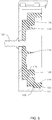
FIG. 5 , theflexible cover 102 may further include aprojection 116 extending from thebase wall 124 towards theperipheral rim 122. As illustrated, theprojection 116 may extend generally orthogonally to thebase wall 124, e.g., along the radial direction R. Thus, in this example, theflexible cover 102 of theouter masking fixture 100 may include aprojection 116 which extends inward, e.g., towards theworkpiece 10, along the radial direction R from thebase wall 124, and aflexible cover 202 of a correspondinginner masking fixture 200 may include a projection 216 which extends outward, e.g., towards theworkpiece 10, along the radial direction R from abase wall 224 of theinner masking fixture 200. - The
flexible cover 102 may also include aport 112 formed in thebase wall 124 for connecting a purge air supply. As illustrated, theport 112 may extend through thebase wall 124 to provide fluid communication with theenclosure 114, e.g., for a purge air supply. In some embodiments, a portion of theenclosure 114 may define apurge flow cavity 130. Thepurge flow cavity 130, when provided, may be a pressurizable cavity defined by thebase wall 124 and selectedsidewalls 128 of the plurality ofsidewalls 128. In some embodiments, theprojection 116 may partially define thepurge flow cavity 130. Thepurge flow cavity 130 may be further defined by theworkpiece 10, e.g., as shown in the illustrated embodiments, at least one side of thepurge flow cavity 130 is formed by theworkpiece 10, such as by theouter band 20 of the illustratedexample nozzle segment 10. As best seen inFIG. 2 , in embodiments where theworkpiece 10 is a hollow workpiece including aninternal cavity 16, thepurge flow cavity 130 may be in fluid communication with theinternal cavity 16 of theworkpiece 10. - As may be seen in
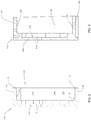
FIGS. 6 and8 , therigid cover 104 of theouter masking fixture 100 may include abase wall 132 and a plurality ofside walls 134 extending generally orthogonal to thebase wall 132 of therigid cover 104. Similarly as noted above with respect to theflexible cover 102, for purposes of illustration only, thebase wall 132 may be referred to as defining a bottom portion of therigid cover 104 and thesidewalls 134 may be referred to as extending upward away from thebase wall 132. Aninner surface 133 of thebase wall 132 of therigid cover 104 andinner surfaces 135 of the plurality ofsidewalls 134 of therigid cover 104 define acavity 136 of therigid cover 104. As illustrated inFIGS. 2 through 5 , theflexible cover 102 may be received within thecavity 136 of therigid cover 104. Similarly, as seen inFIGS. 7 and9 , therigid cover 204 of theinner masking fixture 200 may also include abase wall 232 and a plurality ofside walls 234 and acavity 236 defined bysurfaces - In some embodiments, as best seen in
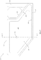
FIG. 4 , therigid cover 104 of theouter masking fixture 104 may advantageously include achamfer 118 defined in a corner of eachsidewall 134 of therigid cover 104. For example,chamfer 118 may be defined at each top corner of thesidewalls 134, e.g., the corner of eachsidewall 134 distal from thebase wall 132 and on theinner surface 135 of the sidewall, e.g., the side of thesidewall 134 which abuts the outer surface of theflexible cover 102 when theflexible cover 102 is received within thecavity 136 of therigid cover 104.Such chamfers 118 may advantageously facilitate installation of theflexible cover 102 within thecavity 136 of therigid cover 104. - Additionally, some embodiments of the
flexible cover 102 may include an outer surface configured to form an interference fit with a corresponding portion of theinner surfaces 135 of the plurality ofsidewalls 134 of therigid cover 104. As best seen inFIG. 4 , theflexible cover 102 may be compressed from its original shape (the original shape shown in dashed lines inFIG. 4 ) due to the interference fit with therigid cover 104. Such compression of theflexible cover 102 may advantageously promote continuous and complete sealing around theworkpiece 10. In particular embodiments where theworkpiece 10 includes irregular shapes and/or concave shapes, such compression of theflexible cover 102 may help to ensure theflexible cover 102 conforms to the shape of theworkpiece 10 to sealingly engage theworkpiece 10. For example, in embodiments where theworkpiece 10 is anozzle segment 10 including aplatform 20 and hooks 22 and 24, compression of theflexible cover 102 due to the interference fit with therigid cover 104 may promote sealing engagement of theflexible cover 102, e.g., fully around the perimeter of theplatform 20. In some embodiments, the portion of theinner surfaces 135 of the plurality ofsidewalls 134 of therigid cover 104 with which the outer surface of theflexible cover 102 is configured to form an interference fit may include thechamfer 118. Additionally, in some embodiments the outer surface of theflexible cover 102 may include a first portion configured to form an interference fit with a first corresponding portion of theinner surfaces 135 of the plurality ofsidewalls 134 of therigid cover 104 and a second portion of the outer surface of theflexible cover 102 configured to form a clearance fit with a second corresponding portion of theinner surfaces 135 of the plurality ofsidewalls 134 of therigid cover 104, e.g., as illustrated inFIG. 3 , aclearance 108 may be defined between theflexible cover 102 and therigid cover 104. - In various embodiments, the
outer masking fixture 100 may be paired with a second complementary masking fixture, such as theinner masking fixture 200. It is to be understood that the complementary masking fixture, e.g.,inner masking fixture 200, may have corresponding features to those of theouter masking fixture 100. In some embodiments, for example, theinner masking fixture 200 may be a mirror image of thefirst masking fixture 100. - In some embodiments, the
inner masking fixture 200 may include aflexible cover 202 and arigid cover 204. Theflexible cover 202 may include aperipheral rim 222, abase wall 224, and a plurality ofsidewalls 228, similar to theperipheral rim 122,base wall 124, and plurality ofsidewalls 128 of theflexible cover 102 of theouter masking fixture 100. Theflexible cover 202 of theinner masking fixture 200 may further include anenclosure 214 defined by thebase wall 224 and the plurality ofsidewalls 228, similar to theenclosure 114 offlexible cover 102. As described above with reference to theinner rim 126, theflexible cover 202 of theinner masking fixture 200 may include an inner 226, and theinner rim 226 may be configured to support and stabilize theinner end 14 of theworkpiece 10, e.g., as shown inFIG. 2 . - A
connector 106 may be provided, e.g., in or through thebase walls cover connector 106 permits a fluid flow supply, e.g., a purge flow supply, to be connected to theouter masking fixture 100 and in fluid communication with theenclosure 114 of theflexible cover 102, and in particular with thepurge flow cavity 130 therein. Theconnector 106 may be connected to or may pass through aport 110 in therigid cover 104 and aport 112 in theflexible cover 102 to permit fluid flow, e.g., purge air flow, into and through themasking fixture 100. Asimilar connector 206 may be provided in theinner masking fixture 200, along withports flexible cover 202 andrigid cover 204, respectively. Theconnector 206 may permit purge air flow into a pressurizablepurge flow cavity 230 in theinner masking fixture 200. - As illustrated in
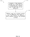
FIG. 12 , embodiments of the present disclosure include amethod 1000 of treating aworkpiece 10. Theexemplary method 1000 may include aninitial step 1010 of positioning afirst masking fixture 100 on afirst end 12 of theworkpiece 10 and positioning asecond masking fixture 200 on asecond end 14 of theworkpiece 10. In some embodiments, positioning thefirst masking fixture 100 may include forming apurge flow cavity 130 between aflexible sealing cover 102 of thefirst masking fixture 100 and thefirst end 12 of theworkpiece 10. Further, in some embodiments positioning thesecond masking fixture 200 may include forming a secondpurge flow cavity 230 between a sealingcover 202 of thesecond masking fixture 200 and thesecond end 14 of theworkpiece 10. - The
example method 100 may include abrasive blasting, e.g., directing a pressurized fluid jet comprising an abrasive media, e.g., sand, entrained in the pressurized fluid jet against an exterior surface of theworkpiece 10 atstep 1020. Theexemplary method 1000 may also include directing a purge flow through theworkpiece 10 while directing the pressurized fluid jet against the exterior surface, e.g., also atstep 1020. As shown in the illustrated embodiment, e.g., inFIG. 2 , the method may include directing the purge flow through aninterior cavity 16 of theworkpiece 10. The exemplary method may further include directing the purge flow from theinterior cavity 16 of theworkpiece 10 to an ambient environment around theworkpiece 10 through a plurality of holes 18 (FIG. 3 ) in the exterior surface of theworkpiece 10. For example, embodiments of theholes 18 may include cooling holes or holes providing other primary functions such as ventilation, lubrication, etc., or the holes may serve as hydraulic ducts. It should be understood that theholes 18 are not limited to any particular primary function. Rather, the primary function of theholes 18 may be cooling, lubrication, or any other suitable function which may be impeded or impaired by abrasive media trapped within theholes 18 such that it is desired to prevent or remove entrapped abrasive media in theholes 18. Directing the purge flow through theinterior cavity 16 and holes 18 during the abrasive blasting may be effective to prevent abrasive media, e.g., sand, from entering theholes 18 and/orcavity 16. - In some embodiments, the method of treating the
workpiece 10 may include positioning theworkpiece 10 in a vertical position. For example, in embodiments where theworkpiece 10 is a nozzle segment, thenozzle segment 10 may include a narrower trailing edge 26 (FIG. 1 ). In such embodiments, positioning thenozzle segment 10 in a vertical position may include positioning the trailingedge 26 downward. Positioning theworkpiece 10 in a vertical position may advantageously promote gravitational flow of the abrasive media away from theworkpiece 10 after impingement of the abrasive media on the exterior surface of theworkpiece 10 to reduce or avoid entrapped abrasive media, e.g., inholes 18 and/orcavity 16. - In some embodiments, the method of treating the
workpiece 10 may include over pressurizing theworkpiece 10, in particular theinterior cavity 16 thereof. For example, the pressure of the purge flow may be greater than the pressure of the pressurized jet. In some embodiments, the pressure of the purge flow may be at least 3 bar greater than the pressure of the pressurized jet. Such pressure differences may advantageously prevent the abrasive media from entering theholes 18 and/orcavity 16 of theworkpiece 10. - In various embodiments, one or both of the masking
fixtures connector 106 and/or 206 for directing the purge flow therethrough. Thus, in some embodiments, directing the purge flow through theworkpiece 10 atstep 1020 may include directing the purge flow through the first masking fixture 100 (e.g., viaconnector 106 andports 110, 112) into theinterior cavity 16 of theworkpiece 10. Some embodiments of directing the purge flow through theworkpiece 10 atstep 1020 may also or instead include directing the purge flow through the second masking fixture 200 (e.g., viaconnector 206 andports 210, 212) into theinterior cavity 16 of theworkpiece 16. - In some embodiments, positioning the
first masking fixture 100 on thefirst end 12 may include sealingly engaging theflexible sealing cover 102 of thefirst masking fixture 100 with thefirst end 12 of theworkpiece 10. In some embodiments, positioning thesecond masking fixture 200 may include sealingly engaging theflexible sealing cover 202 of thesecond masking fixture 200 with thesecond end 14 of theworkpiece 10. In such embodiments, theflexible covers ends workpiece 10. Further in such embodiments, therigid covers flexible covers - In some embodiments, positioning the
first masking fixture 100 on thefirst end 12 may include sealingly engaging theflexible sealing cover 102 of thefirst masking fixture 100 with arigid cover 104 of thefirst masking fixture 100. In some embodiments, positioning thesecond masking fixture 200 on thesecond end 14 may include sealingly engaging theflexible sealing cover 202 of thesecond masking fixture 200 with arigid cover 204 of thesecond masking fixture 200. - The method according to the present invention includes fastening together the
first masking fixture 100 and thesecond masking fixture 200 about theworkpiece 10. Fastening is performed after positioning theflexible covers rigid covers workpiece 10. The maskingfixtures fasteners rigid covers fasteners flexible covers ends workpiece 10 and with therigid covers fixtures - This written description uses examples to disclose the invention, including the best mode, and also to enable any person skilled in the art to practice the invention, including making and using any devices or systems and performing any incorporated methods. The patentable scope of the invention is defined by the claims, and may include other examples that occur to those skilled in the art.
Claims (13)
- A method of repairing a workpiece (10), the method comprising:positioning a first masking fixture (100) on a first end (12) of the workpiece (10) and positioning a second masking fixture (200) on a second end (14) of the workpiece (10) prior to directing the pressurized fluid jet,directing a pressurized fluid jet comprising an abrasive media entrained in the pressurized fluid jet against an exterior surface of the workpiece (10); anddirecting a purge flow through the workpiece (10) while directing the pressurized fluid jet against the exterior surface,characterized in that the method further comprises fastening together the first masking fixture (100) and the second masking fixture (200) about the workpiece (10) using a plurality of fasteners (120, 220) extending from a rigid cover (104, 204) included in each masking fixture (100, 200) prior to directing the pressurized fluid jet.
- The method of claim 1, wherein directing the purge flow comprises directing the purge flow through an interior cavity (16) of the workpiece (10).
- The method of claim 1 or claim 2, wherein directing the purge flow further comprises directing the purge flow from the interior cavity (16) of the workpiece (10) to an ambient environment around the workpiece (10) through a plurality of holes (18) in the exterior surface of the workpiece (10).
- The method of any preceding claim, wherein positioning the first masking fixture (100) comprises forming a purge flow cavity (130) between a flexible sealing cover (102) of the first masking fixture (100) and the first end (12) of the workpiece (10) and positioning the second masking fixture (200) comprises forming a second purge flow cavity (230) between a sealing cover (202) of the second masking fixture (200) and the second end of the workpiece (10).
- The method of any preceding claim, wherein positioning the first masking fixture (100) further comprises sealingly engaging the flexible sealing cover (102) of the first masking fixture (100) with a first end (12) of the workpiece (10) and wherein positioning the second masking fixture (200) further comprises sealingly engaging the flexible sealing cover (202) of the second masking fixture (200) with a second end (14) of the workpiece (10).
- The method of claim 5, wherein positioning the first masking fixture (100) further comprises sealingly engaging the flexible sealing cover (102) of the first masking fixture (100) with the rigid cover (104) of the first masking fixture (100) and wherein positioning the second masking fixture (200) further comprises sealingly engaging the flexible sealing cover (202) of the second masking fixture (200) with the rigid cover (204) of the second masking fixture (200).
- The method of any preceding claim, wherein directing the purge flow comprises directing the purge flow through the first masking fixture (100) into an interior cavity (16) of the workpiece (10) and through the second masking fixture (200) into the interior cavity (16) of the workpiece (10).
- The method of claim 7, wherein directing the purge flow further comprises directing the purge flow from the interior cavity (16) of the workpiece (10) to an ambient environment around the workpiece (10) through a plurality of holes (18) in the exterior surface of the workpiece (10).
- The method of any preceding claim, wherein a pressure of the purge flow is greater than a pressure of the pressurized jet.
- The method of claim 9, wherein the pressure of the purge flow is at least 3 bar greater than the pressure of the pressurized jet.
- A masking fixture (100) for protecting a workpiece (10) during repair of the workpiece (10), the masking fixture (100) comprising:
a flexible cover (102), the flexible cover (102) comprising:a peripheral rim (122);a base wall (124) parallel to and spaced from the peripheral rim (122);a plurality of sidewalls (128) extending between the peripheral rim (122) and the base wall (124), the plurality of sidewalls (128) generally orthogonal to the peripheral rim (122) and the base wall (124);an enclosure (114) defined by the base wall (124) and the plurality of sidewalls (128);an internal rim (126) extending parallel to the peripheral rim (122) and the base wall (124), the internal rim (126) positioned within the enclosure (114) between the base wall (124) and the peripheral rim (122);a projection (116) extending from the base wall (124) towards the peripheral rim (122), the projection (116) generally orthogonal to the base wall (124); anda port (112) formed in the base wall (124) for connecting a purge air supply, the port (112) in fluid communication with the enclosure (114),characterized by a plurality of fasteners (120, 220) extending from a rigid cover (104, 204) included in each masking fixture (100, 200) for securing the masking fixture (100) to a complementary masking fixture (200). - The masking fixture (100) of claim 11, further comprising a purge flow cavity (130) within the enclosure (114), the purge flow cavity (130) defined by the base wall (124) and selected sidewalls (128) of the plurality of sidewalls (128).
- The masking fixture (100) of claim 11 or claim 12, wherein the rigid cover (104) comprising a base wall (132) and a plurality of sidewalls (134) extending generally orthogonal to the base wall (132) of the rigid cover (104), an inner surface of the base wall (132) of the rigid cover (104) and inner surfaces of the plurality of sidewalls (134) of the rigid cover (104) defining a cavity (136) of the rigid cover (104), the flexible cover (102) received within the cavity (136) of the rigid cover (104).
Applications Claiming Priority (1)
| Application Number | Priority Date | Filing Date | Title |
|---|---|---|---|
| PL42161917 | 2017-05-17 |
Publications (2)
| Publication Number | Publication Date |
|---|---|
| EP3403764A1 EP3403764A1 (en) | 2018-11-21 |
| EP3403764B1 true EP3403764B1 (en) | 2020-11-04 |
Family
ID=62148179
Family Applications (1)
| Application Number | Title | Priority Date | Filing Date |
|---|---|---|---|
| EP18171489.0A Active EP3403764B1 (en) | 2017-05-17 | 2018-05-09 | Method of repairing a workpiece and masking fixture |
Country Status (4)
| Country | Link |
|---|---|
| US (1) | US10913138B2 (en) |
| EP (1) | EP3403764B1 (en) |
| JP (1) | JP7399605B2 (en) |
| CN (1) | CN108952851A (en) |
Families Citing this family (2)
| Publication number | Priority date | Publication date | Assignee | Title |
|---|---|---|---|---|
| US11566298B2 (en) * | 2019-05-08 | 2023-01-31 | Raytheon Technologies Corporation | Systems and methods for manufacturing components for gas turbine engines |
| CN114714175B (en) * | 2022-04-28 | 2023-09-19 | 一汽解放汽车有限公司 | Micropore flow control device and control method |
Family Cites Families (27)
| Publication number | Priority date | Publication date | Assignee | Title |
|---|---|---|---|---|
| JPS5758993A (en) * | 1980-09-29 | 1982-04-09 | Mitsubishi Heavy Ind Ltd | Sealing device for back sealing gas |
| US4530861A (en) * | 1983-12-19 | 1985-07-23 | General Electric Company | Method and apparatus for masking a surface of a blade member |
| US4612737A (en) * | 1985-07-05 | 1986-09-23 | Rohr Industries, Inc. | Grit blast drilling of advanced composite perforated sheet |
| US5063015A (en) * | 1989-03-13 | 1991-11-05 | Cold Jet, Inc. | Method for deflashing articles |
| US5006207A (en) * | 1989-07-27 | 1991-04-09 | Gerber Plumbing Fixtures Corp. | Method of decorating an expansive surface of a metallic faucet spout or other plumbing fixture |
| JPH04275875A (en) * | 1990-12-28 | 1992-10-01 | Nippon Steel Corp | Surface layer treatment device for surface treated steel sheet and manufacturing equipment of electro-resistance-welded steel pipe |
| US5247766A (en) * | 1992-01-31 | 1993-09-28 | Kildea Robert J | Process for improving cooling hole flow control |
| US6158955A (en) * | 1999-06-03 | 2000-12-12 | General Electric Company | Welding method and assembly therefor |
| US6485655B1 (en) * | 2001-08-02 | 2002-11-26 | General Electric Company | Method and apparatus for retaining an internal coating during article repair |
| JP2006062041A (en) | 2004-08-27 | 2006-03-09 | Toyota Motor Corp | Solid particle jetting device and method |
| US7134946B1 (en) * | 2004-12-13 | 2006-11-14 | Cool Clean Technologies, Inc. | Apparatus to treat and inspect a substrate |
| JP2007098500A (en) | 2005-10-03 | 2007-04-19 | Bridgestone Corp | Wafer machining method |
| JP2009233820A (en) * | 2008-03-28 | 2009-10-15 | Tdk Corp | Blasting method and device |
| US8430256B2 (en) * | 2008-09-03 | 2013-04-30 | Motorola Mobility Llc | Extruded housing for hand-held device with a cap for covering two or more adjacent sides |
| US20100135822A1 (en) * | 2008-11-28 | 2010-06-03 | Remo Marini | Turbine blade for a gas turbine engine |
| US20100210186A1 (en) * | 2009-02-18 | 2010-08-19 | Lai International, Inc. | Multi-head fluid jet cutting system |
| US8967078B2 (en) * | 2009-08-27 | 2015-03-03 | United Technologies Corporation | Abrasive finish mask and method of polishing a component |
| US20120090278A1 (en) * | 2010-10-13 | 2012-04-19 | Mallinckrodt Llc | Disposable transdermal patch containment |
| US20120171045A1 (en) | 2011-01-03 | 2012-07-05 | United Technologies Corporation | Turbine component fixture and coating system |
| US8887662B2 (en) * | 2011-12-29 | 2014-11-18 | General Electric Company | Pressure masking systems and methods for using the same |
| US8985049B2 (en) * | 2011-12-29 | 2015-03-24 | General Electric Company | Pressure maskers and pressure masking systems |
| US20130167870A1 (en) * | 2011-12-29 | 2013-07-04 | Mark Carmine Bellino | Pressure masking systems and methods for using the same |
| US9193111B2 (en) * | 2012-07-02 | 2015-11-24 | United Technologies Corporation | Super polish masking of integrally bladed rotor |
| EP2692995B1 (en) * | 2012-07-30 | 2017-09-20 | Ansaldo Energia IP UK Limited | Stationary gas turbine engine and method for performing maintenance work |
| US20170053678A1 (en) * | 2015-08-20 | 2017-02-23 | HGST Netherlands B.V. | Adhesive cover seal for hermetically-sealed data storage device |
| US20170067561A1 (en) * | 2015-09-04 | 2017-03-09 | Caterpillar Inc. | Face Seal with Backup Ring |
| RU2019111716A (en) * | 2016-09-19 | 2020-10-19 | Маккормик Энд Компани, Инкорпорейтед | THREE-DOOR LID AND CONTAINER IN WHICH IT IS USED |
-
2018
- 2018-05-09 EP EP18171489.0A patent/EP3403764B1/en active Active
- 2018-05-15 JP JP2018093512A patent/JP7399605B2/en active Active
- 2018-05-17 CN CN201810473201.1A patent/CN108952851A/en active Pending
- 2018-05-17 US US15/982,746 patent/US10913138B2/en active Active
Non-Patent Citations (1)
| Title |
|---|
| None * |
Also Published As
| Publication number | Publication date |
|---|---|
| EP3403764A1 (en) | 2018-11-21 |
| US20180333824A1 (en) | 2018-11-22 |
| CN108952851A8 (en) | 2019-01-29 |
| US10913138B2 (en) | 2021-02-09 |
| JP2019038096A (en) | 2019-03-14 |
| CN108952851A (en) | 2018-12-07 |
| JP7399605B2 (en) | 2023-12-18 |
Similar Documents
| Publication | Publication Date | Title |
|---|---|---|
| TWI649493B (en) | Insert kit, blade, gas turbine, and method of manufacturing the blade | |
| US4426095A (en) | Flexible seal | |
| EP3403764B1 (en) | Method of repairing a workpiece and masking fixture | |
| EP2289666B1 (en) | Abrasive finish mask and method of masking a component | |
| US20070014668A1 (en) | Seal and locking plate for turbine rotor assembly between turbine blade and turbine vane | |
| US7124572B2 (en) | Recuperator and turbine support adapter for recuperated gas turbine engines | |
| CN103089338B (en) | Turbine and method thereof including interior-outer turbine shroud black box | |
| JP2005201267A (en) | Turbofan jet engine having ancillaries distribution support | |
| US9920869B2 (en) | Cooling systems for gas turbine engine components | |
| JP2005299666A (en) | Flexible seal assembly between gas turbine structural components and its mounting method | |
| JP2007513281A (en) | Peristaltic joint between combustor wall and nozzle platform | |
| US10473328B2 (en) | Acoustic damping system for a combustor of a gas turbine engine | |
| EP2520765A2 (en) | Two-piece side seal with covers | |
| US6079944A (en) | Gas turbine stationary blade double cross type seal device | |
| US7845649B2 (en) | Methods and apparatus to facilitate sealing high pressure joints | |
| US10012389B2 (en) | Case with integral heat shielding | |
| CN106015784B (en) | Unmanned boat contained pipeline connector | |
| GB2530669A (en) | Turbine wheel for a turbine engine | |
| US9771819B2 (en) | Anti-corner-leakage seal in gas turbine | |
| KR101206233B1 (en) | Combination for sea chest hole of vessel | |
| CN107461274B (en) | Engine oil flow control by deflection | |
| KR20190086566A (en) | A turbocharger having a sealing surface between the nozzle ring and the turbine housing | |
| WO2012023502A1 (en) | Cylinder liner | |
| CN107701247B (en) | Gas turbine guider inner ring impingement cooling structure and gas turbine | |
| CA2686055A1 (en) | Combustion chamber arrangement for operating a gas turbine |
Legal Events
| Date | Code | Title | Description |
|---|---|---|---|
| PUAI | Public reference made under article 153(3) epc to a published international application that has entered the european phase |
Free format text: ORIGINAL CODE: 0009012 |
|
| STAA | Information on the status of an ep patent application or granted ep patent |
Free format text: STATUS: THE APPLICATION HAS BEEN PUBLISHED |
|
| AK | Designated contracting states |
Kind code of ref document: A1 Designated state(s): AL AT BE BG CH CY CZ DE DK EE ES FI FR GB GR HR HU IE IS IT LI LT LU LV MC MK MT NL NO PL PT RO RS SE SI SK SM TR |
|
| AX | Request for extension of the european patent |
Extension state: BA ME |
|
| STAA | Information on the status of an ep patent application or granted ep patent |
Free format text: STATUS: REQUEST FOR EXAMINATION WAS MADE |
|
| 17P | Request for examination filed |
Effective date: 20190521 |
|
| RBV | Designated contracting states (corrected) |
Designated state(s): AL AT BE BG CH CY CZ DE DK EE ES FI FR GB GR HR HU IE IS IT LI LT LU LV MC MK MT NL NO PL PT RO RS SE SI SK SM TR |
|
| STAA | Information on the status of an ep patent application or granted ep patent |
Free format text: STATUS: EXAMINATION IS IN PROGRESS |
|
| 17Q | First examination report despatched |
Effective date: 20190903 |
|
| GRAP | Despatch of communication of intention to grant a patent |
Free format text: ORIGINAL CODE: EPIDOSNIGR1 |
|
| STAA | Information on the status of an ep patent application or granted ep patent |
Free format text: STATUS: GRANT OF PATENT IS INTENDED |
|
| INTG | Intention to grant announced |
Effective date: 20200603 |
|
| GRAS | Grant fee paid |
Free format text: ORIGINAL CODE: EPIDOSNIGR3 |
|
| GRAA | (expected) grant |
Free format text: ORIGINAL CODE: 0009210 |
|
| STAA | Information on the status of an ep patent application or granted ep patent |
Free format text: STATUS: THE PATENT HAS BEEN GRANTED |
|
| AK | Designated contracting states |
Kind code of ref document: B1 Designated state(s): AL AT BE BG CH CY CZ DE DK EE ES FI FR GB GR HR HU IE IS IT LI LT LU LV MC MK MT NL NO PL PT RO RS SE SI SK SM TR |
|
| REG | Reference to a national code |
Ref country code: GB Ref legal event code: FG4D |
|
| REG | Reference to a national code |
Ref country code: CH Ref legal event code: EP |
|
| REG | Reference to a national code |
Ref country code: AT Ref legal event code: REF Ref document number: 1330187 Country of ref document: AT Kind code of ref document: T Effective date: 20201115 |
|
| REG | Reference to a national code |
Ref country code: IE Ref legal event code: FG4D |
|
| REG | Reference to a national code |
Ref country code: DE Ref legal event code: R096 Ref document number: 602018009298 Country of ref document: DE |
|
| REG | Reference to a national code |
Ref country code: NL Ref legal event code: MP Effective date: 20201104 |
|
| REG | Reference to a national code |
Ref country code: AT Ref legal event code: MK05 Ref document number: 1330187 Country of ref document: AT Kind code of ref document: T Effective date: 20201104 |
|
| PG25 | Lapsed in a contracting state [announced via postgrant information from national office to epo] |
Ref country code: FI Free format text: LAPSE BECAUSE OF FAILURE TO SUBMIT A TRANSLATION OF THE DESCRIPTION OR TO PAY THE FEE WITHIN THE PRESCRIBED TIME-LIMIT Effective date: 20201104 Ref country code: RS Free format text: LAPSE BECAUSE OF FAILURE TO SUBMIT A TRANSLATION OF THE DESCRIPTION OR TO PAY THE FEE WITHIN THE PRESCRIBED TIME-LIMIT Effective date: 20201104 Ref country code: PT Free format text: LAPSE BECAUSE OF FAILURE TO SUBMIT A TRANSLATION OF THE DESCRIPTION OR TO PAY THE FEE WITHIN THE PRESCRIBED TIME-LIMIT Effective date: 20210304 Ref country code: NO Free format text: LAPSE BECAUSE OF FAILURE TO SUBMIT A TRANSLATION OF THE DESCRIPTION OR TO PAY THE FEE WITHIN THE PRESCRIBED TIME-LIMIT Effective date: 20210204 Ref country code: GR Free format text: LAPSE BECAUSE OF FAILURE TO SUBMIT A TRANSLATION OF THE DESCRIPTION OR TO PAY THE FEE WITHIN THE PRESCRIBED TIME-LIMIT Effective date: 20210205 |
|
| PG25 | Lapsed in a contracting state [announced via postgrant information from national office to epo] |
Ref country code: ES Free format text: LAPSE BECAUSE OF FAILURE TO SUBMIT A TRANSLATION OF THE DESCRIPTION OR TO PAY THE FEE WITHIN THE PRESCRIBED TIME-LIMIT Effective date: 20201104 Ref country code: AT Free format text: LAPSE BECAUSE OF FAILURE TO SUBMIT A TRANSLATION OF THE DESCRIPTION OR TO PAY THE FEE WITHIN THE PRESCRIBED TIME-LIMIT Effective date: 20201104 Ref country code: BG Free format text: LAPSE BECAUSE OF FAILURE TO SUBMIT A TRANSLATION OF THE DESCRIPTION OR TO PAY THE FEE WITHIN THE PRESCRIBED TIME-LIMIT Effective date: 20210204 Ref country code: IS Free format text: LAPSE BECAUSE OF FAILURE TO SUBMIT A TRANSLATION OF THE DESCRIPTION OR TO PAY THE FEE WITHIN THE PRESCRIBED TIME-LIMIT Effective date: 20210304 Ref country code: LV Free format text: LAPSE BECAUSE OF FAILURE TO SUBMIT A TRANSLATION OF THE DESCRIPTION OR TO PAY THE FEE WITHIN THE PRESCRIBED TIME-LIMIT Effective date: 20201104 Ref country code: PL Free format text: LAPSE BECAUSE OF FAILURE TO SUBMIT A TRANSLATION OF THE DESCRIPTION OR TO PAY THE FEE WITHIN THE PRESCRIBED TIME-LIMIT Effective date: 20201104 Ref country code: SE Free format text: LAPSE BECAUSE OF FAILURE TO SUBMIT A TRANSLATION OF THE DESCRIPTION OR TO PAY THE FEE WITHIN THE PRESCRIBED TIME-LIMIT Effective date: 20201104 |
|
| REG | Reference to a national code |
Ref country code: LT Ref legal event code: MG9D |
|
| PG25 | Lapsed in a contracting state [announced via postgrant information from national office to epo] |
Ref country code: HR Free format text: LAPSE BECAUSE OF FAILURE TO SUBMIT A TRANSLATION OF THE DESCRIPTION OR TO PAY THE FEE WITHIN THE PRESCRIBED TIME-LIMIT Effective date: 20201104 |
|
| PG25 | Lapsed in a contracting state [announced via postgrant information from national office to epo] |
Ref country code: SM Free format text: LAPSE BECAUSE OF FAILURE TO SUBMIT A TRANSLATION OF THE DESCRIPTION OR TO PAY THE FEE WITHIN THE PRESCRIBED TIME-LIMIT Effective date: 20201104 Ref country code: EE Free format text: LAPSE BECAUSE OF FAILURE TO SUBMIT A TRANSLATION OF THE DESCRIPTION OR TO PAY THE FEE WITHIN THE PRESCRIBED TIME-LIMIT Effective date: 20201104 Ref country code: CZ Free format text: LAPSE BECAUSE OF FAILURE TO SUBMIT A TRANSLATION OF THE DESCRIPTION OR TO PAY THE FEE WITHIN THE PRESCRIBED TIME-LIMIT Effective date: 20201104 Ref country code: LT Free format text: LAPSE BECAUSE OF FAILURE TO SUBMIT A TRANSLATION OF THE DESCRIPTION OR TO PAY THE FEE WITHIN THE PRESCRIBED TIME-LIMIT Effective date: 20201104 Ref country code: RO Free format text: LAPSE BECAUSE OF FAILURE TO SUBMIT A TRANSLATION OF THE DESCRIPTION OR TO PAY THE FEE WITHIN THE PRESCRIBED TIME-LIMIT Effective date: 20201104 Ref country code: SK Free format text: LAPSE BECAUSE OF FAILURE TO SUBMIT A TRANSLATION OF THE DESCRIPTION OR TO PAY THE FEE WITHIN THE PRESCRIBED TIME-LIMIT Effective date: 20201104 |
|
| REG | Reference to a national code |
Ref country code: DE Ref legal event code: R097 Ref document number: 602018009298 Country of ref document: DE |
|
| PG25 | Lapsed in a contracting state [announced via postgrant information from national office to epo] |
Ref country code: DK Free format text: LAPSE BECAUSE OF FAILURE TO SUBMIT A TRANSLATION OF THE DESCRIPTION OR TO PAY THE FEE WITHIN THE PRESCRIBED TIME-LIMIT Effective date: 20201104 |
|
| PLBE | No opposition filed within time limit |
Free format text: ORIGINAL CODE: 0009261 |
|
| STAA | Information on the status of an ep patent application or granted ep patent |
Free format text: STATUS: NO OPPOSITION FILED WITHIN TIME LIMIT |
|
| 26N | No opposition filed |
Effective date: 20210805 |
|
| PG25 | Lapsed in a contracting state [announced via postgrant information from national office to epo] |
Ref country code: AL Free format text: LAPSE BECAUSE OF FAILURE TO SUBMIT A TRANSLATION OF THE DESCRIPTION OR TO PAY THE FEE WITHIN THE PRESCRIBED TIME-LIMIT Effective date: 20201104 Ref country code: NL Free format text: LAPSE BECAUSE OF FAILURE TO SUBMIT A TRANSLATION OF THE DESCRIPTION OR TO PAY THE FEE WITHIN THE PRESCRIBED TIME-LIMIT Effective date: 20201104 |
|
| PG25 | Lapsed in a contracting state [announced via postgrant information from national office to epo] |
Ref country code: SI Free format text: LAPSE BECAUSE OF FAILURE TO SUBMIT A TRANSLATION OF THE DESCRIPTION OR TO PAY THE FEE WITHIN THE PRESCRIBED TIME-LIMIT Effective date: 20201104 |
|
| PG25 | Lapsed in a contracting state [announced via postgrant information from national office to epo] |
Ref country code: MC Free format text: LAPSE BECAUSE OF FAILURE TO SUBMIT A TRANSLATION OF THE DESCRIPTION OR TO PAY THE FEE WITHIN THE PRESCRIBED TIME-LIMIT Effective date: 20201104 Ref country code: LU Free format text: LAPSE BECAUSE OF NON-PAYMENT OF DUE FEES Effective date: 20210509 |
|
| REG | Reference to a national code |
Ref country code: BE Ref legal event code: MM Effective date: 20210531 |
|
| PG25 | Lapsed in a contracting state [announced via postgrant information from national office to epo] |
Ref country code: IE Free format text: LAPSE BECAUSE OF NON-PAYMENT OF DUE FEES Effective date: 20210509 |
|
| PG25 | Lapsed in a contracting state [announced via postgrant information from national office to epo] |
Ref country code: IS Free format text: LAPSE BECAUSE OF FAILURE TO SUBMIT A TRANSLATION OF THE DESCRIPTION OR TO PAY THE FEE WITHIN THE PRESCRIBED TIME-LIMIT Effective date: 20210304 |
|
| PG25 | Lapsed in a contracting state [announced via postgrant information from national office to epo] |
Ref country code: BE Free format text: LAPSE BECAUSE OF NON-PAYMENT OF DUE FEES Effective date: 20210531 |
|
| PG25 | Lapsed in a contracting state [announced via postgrant information from national office to epo] |
Ref country code: CY Free format text: LAPSE BECAUSE OF FAILURE TO SUBMIT A TRANSLATION OF THE DESCRIPTION OR TO PAY THE FEE WITHIN THE PRESCRIBED TIME-LIMIT Effective date: 20201104 |
|
| PG25 | Lapsed in a contracting state [announced via postgrant information from national office to epo] |
Ref country code: HU Free format text: LAPSE BECAUSE OF FAILURE TO SUBMIT A TRANSLATION OF THE DESCRIPTION OR TO PAY THE FEE WITHIN THE PRESCRIBED TIME-LIMIT; INVALID AB INITIO Effective date: 20180509 |
|
| PGFP | Annual fee paid to national office [announced via postgrant information from national office to epo] |
Ref country code: IT Payment date: 20230420 Year of fee payment: 6 Ref country code: FR Payment date: 20230420 Year of fee payment: 6 Ref country code: DE Payment date: 20230419 Year of fee payment: 6 Ref country code: CH Payment date: 20230602 Year of fee payment: 6 |
|
| PGFP | Annual fee paid to national office [announced via postgrant information from national office to epo] |
Ref country code: GB Payment date: 20230420 Year of fee payment: 6 |
|
| REG | Reference to a national code |
Ref country code: DE Ref legal event code: R081 Ref document number: 602018009298 Country of ref document: DE Owner name: GENERAL ELECTRIC TECHNOLOGY GMBH, CH Free format text: FORMER OWNER: GENERAL ELECTRIC COMPANY, SCHENECTADY, NY, US |
|
| REG | Reference to a national code |
Ref country code: GB Ref legal event code: 732E Free format text: REGISTERED BETWEEN 20240222 AND 20240228 |