EP3403684A1 - Zentralvenöse katheteranordnung - Google Patents
Zentralvenöse katheteranordnung Download PDFInfo
- Publication number
- EP3403684A1 EP3403684A1 EP18170645.8A EP18170645A EP3403684A1 EP 3403684 A1 EP3403684 A1 EP 3403684A1 EP 18170645 A EP18170645 A EP 18170645A EP 3403684 A1 EP3403684 A1 EP 3403684A1
- Authority
- EP
- European Patent Office
- Prior art keywords
- catheter
- tube
- proximal
- housing
- hose
- Prior art date
- Legal status (The legal status is an assumption and is not a legal conclusion. Google has not performed a legal analysis and makes no representation as to the accuracy of the status listed.)
- Granted
Links
Images

Classifications
-
- A—HUMAN NECESSITIES
- A61—MEDICAL OR VETERINARY SCIENCE; HYGIENE
- A61M—DEVICES FOR INTRODUCING MEDIA INTO, OR ONTO, THE BODY; DEVICES FOR TRANSDUCING BODY MEDIA OR FOR TAKING MEDIA FROM THE BODY; DEVICES FOR PRODUCING OR ENDING SLEEP OR STUPOR
- A61M25/00—Catheters; Hollow probes
- A61M25/0097—Catheters; Hollow probes characterised by the hub
-
- A—HUMAN NECESSITIES
- A61—MEDICAL OR VETERINARY SCIENCE; HYGIENE
- A61M—DEVICES FOR INTRODUCING MEDIA INTO, OR ONTO, THE BODY; DEVICES FOR TRANSDUCING BODY MEDIA OR FOR TAKING MEDIA FROM THE BODY; DEVICES FOR PRODUCING OR ENDING SLEEP OR STUPOR
- A61M25/00—Catheters; Hollow probes
- A61M25/0009—Making of catheters or other medical or surgical tubes
- A61M25/0014—Connecting a tube to a hub
-
- A—HUMAN NECESSITIES
- A61—MEDICAL OR VETERINARY SCIENCE; HYGIENE
- A61M—DEVICES FOR INTRODUCING MEDIA INTO, OR ONTO, THE BODY; DEVICES FOR TRANSDUCING BODY MEDIA OR FOR TAKING MEDIA FROM THE BODY; DEVICES FOR PRODUCING OR ENDING SLEEP OR STUPOR
- A61M25/00—Catheters; Hollow probes
- A61M2025/0004—Catheters; Hollow probes having two or more concentrically arranged tubes for forming a concentric catheter system
- A61M2025/0006—Catheters; Hollow probes having two or more concentrically arranged tubes for forming a concentric catheter system which can be secured against axial movement, e.g. by using a locking cuff
-
- A—HUMAN NECESSITIES
- A61—MEDICAL OR VETERINARY SCIENCE; HYGIENE
- A61M—DEVICES FOR INTRODUCING MEDIA INTO, OR ONTO, THE BODY; DEVICES FOR TRANSDUCING BODY MEDIA OR FOR TAKING MEDIA FROM THE BODY; DEVICES FOR PRODUCING OR ENDING SLEEP OR STUPOR
- A61M25/00—Catheters; Hollow probes
- A61M25/0067—Catheters; Hollow probes characterised by the distal end, e.g. tips
- A61M25/008—Strength or flexibility characteristics of the catheter tip
- A61M2025/0081—Soft tip
-
- A—HUMAN NECESSITIES
- A61—MEDICAL OR VETERINARY SCIENCE; HYGIENE
- A61M—DEVICES FOR INTRODUCING MEDIA INTO, OR ONTO, THE BODY; DEVICES FOR TRANSDUCING BODY MEDIA OR FOR TAKING MEDIA FROM THE BODY; DEVICES FOR PRODUCING OR ENDING SLEEP OR STUPOR
- A61M25/00—Catheters; Hollow probes
- A61M25/01—Introducing, guiding, advancing, emplacing or holding catheters
- A61M2025/0175—Introducing, guiding, advancing, emplacing or holding catheters having telescopic features, interengaging nestable members movable in relations to one another
-
- A—HUMAN NECESSITIES
- A61—MEDICAL OR VETERINARY SCIENCE; HYGIENE
- A61M—DEVICES FOR INTRODUCING MEDIA INTO, OR ONTO, THE BODY; DEVICES FOR TRANSDUCING BODY MEDIA OR FOR TAKING MEDIA FROM THE BODY; DEVICES FOR PRODUCING OR ENDING SLEEP OR STUPOR
- A61M25/00—Catheters; Hollow probes
- A61M25/01—Introducing, guiding, advancing, emplacing or holding catheters
- A61M2025/018—Catheters having a lateral opening for guiding elongated means lateral to the catheter
Definitions
- the invention relates to a central venous catheter arrangement for applying a central access to a venous system of a patient comprising a catheter tube for insertion into a vein of the venous system with a catheter tip distal end of the tube and a proximal end of the tube, which is fluidly connectable to at least one catheter lead.
- Central venous catheter assemblies are also referred to as central venous catheters or central venous accesses and are intended for use in infusion therapy.
- a thin and flexible plastic tubing is provided as a catheter tube, at the distal end of the tube, a catheter tip is integrally formed.
- the distal tube end of the catheter tube is inserted into a vein of the patient in a manner well known in the field of medical technology and advanced in the direction of the heart.
- the catheter tip is usually positioned in the region of the right atrium of the patient.
- the proximal end of the tube remains after application of the access on the body outside of the patient and is connected in known central venous catheters via a fixing fluid-conducting with at least one catheter lead.
- This connection between the catheter tube and the fixing element and / or the catheter supply line is usually carried out firmly in the sense of one piece and / or not nondestructive solvable.
- the central venous access is created via different veins or via different entry points on the body of a patient.
- the length of the catheter tube must be selected depending on the medical indication and / or the body size of the respective patient.
- Known central venous catheter arrangements are therefore available in different designs concerning the tube length between the proximal and the distal end of the tube.
- the object of the invention is to provide a central venous catheter assembly of the type mentioned, which allows a universal use.
- a connecting device is provided with a housing and a locking unit, wherein the proximal end of the hose is detachably fixed to the connecting device, that the catheter tube starting from the can be shortened proximal hose end to achieve a selected length of hose between the proximal and distal end of the hose, and wherein the proximal end of the hose by means of the connecting device fluidly connected to the at least one catheter lead is connectable.
- the at least one catheter supply line can be a lumen for supplying a medication fluid, which has a catheter attachment at its proximal end, which can in particular be a luer-lock connection known as such.
- distal means an orientation towards the body center and “proximally” an orientation away from the body center.
- shortenable or “shortenable” in the sense of the invention means a change in the length between the proximal and the distal end of the tube, which, however, does not necessarily have to be accompanied by a separation of a tube section.
- arranging a hose section in the form of a loop, a loop or the like can effect a change in the length between the hose ends and thus a shortening in the sense of the invention.
- releasable in the sense of the invention is meant a nondestructive separability.
- the term “releasable” in the context of the invention comprises a recombinability that can be produced without further ado after a preceding non-destructive separation.
- the locking unit is movable relative to the housing from a locking position to a release position, wherein the proximal end of the hose is in the locking position in operative connection with the locking unit and is fixed by means of this on the housing and wherein the proximal end of the hose in the release position of the housing is detachable.
- the locking unit may advantageously comprise a clamping element, which is in the locking position with a jacket portion of the proximal end of the hose in a releasable clamping connection. In this way, a particularly reliable and, if necessary, easily detachable connection of the proximal end of the hose to the connecting device is achieved. Accordingly, this embodiment of the invention provides a particularly easy and reliable manageable catheter assembly.
- the locking unit releases a housing opening in the release position, through which at least a portion of the proximal Hose end can be removed from the housing.
- the housing opening is covered by the locking unit at least in sections.
- at least a portion of the proximal end of the hose is disposed in the housing. It is advantageous if the housing opening is aligned substantially radially to the lateral surface of the proximal end of the tube. Thus, good accessibility and manual removal of the proximal end of the hose from the housing is achieved.
- the locking unit is pivotally mounted relative to the housing on this.
- the locking unit is pivotable about a pivot axis oriented transversely to the axial direction of the proximal end of the hose. A particularly cost-effective production is achieved when the locking unit is attached by means of a film hinge to the housing.
- the housing has a substantially coaxial with the proximal end of the tube extending cylindrical housing portion which surrounds the proximal end of the tube radially at least partially.
- the cylindrical housing section forms an extension of the housing, which extends in the direction of the proximal tube section.
- the cone allows a less disturbing to the patient system of the catheter assembly at the relevant entry point of the catheter tube into the body of the patient.
- the cone-shaped design advantageously prevents bleeding in the area of the entry site.
- the cylindrical housing portion is formed by a hose member whose inner diameter substantially corresponds to the outer diameter of the catheter tube, so that it is guided in a release position of the locking unit axially movable in the hose member.
- the hose member is designed so flexible that on the one hand comfortable conditioning of the cylindrical housing portion at the entry point and on the other hand sufficient radial support of the proximal end of the hose is achieved against unwanted kinking.
- the connecting device has at least one connection element, to which at least one catheter supply line can be connected and thus fluid-conductively connected to the catheter tube.
- the at least one connecting element is advantageously arranged on the proximal end region of the housing.
- the connection element is a luer-lock connection known as such in the field of medical technology.
- the catheter tip is designed atraumatic, especially as a soft tip.
- Atraumatic catheter tips are generally known as such in the field of medical technology.
- the atraumatic catheter tip is such, in particular soft and / or flexible, designed such that injury to the vein during advancement of the distal catheter tube is avoided.
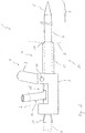
- a central venous catheter assembly 1 is intended for use with infusion therapy.
- the catheter assembly 1 comprises a catheter tube 2 for insertion into a vein of a patient having a distal end of the tube 3 and a proximal end 4 of the tube.
- a specifically shaped catheter tip 5 is integrally formed.
- the distal end of the tube 3 is inserted into a vein of the patient from a body entry point in a manner well known in the medical arts, and the catheter tube 2 is advanced in the vein until the catheter tip 5 becomes a desired one Reached position.
- catheter supply line 6 is a connecting device 7 with a housing 8 and a locking unit 9 is provided.
- the proximal end of the tube 4 is detachably fixed to the connecting device 7 in a manner described in more detail below.
- the locking unit 9 of the connecting device 7 is pivotally attached relative to the housing 8 at this.
- the connecting device 7 has a pivot axis 10, which is oriented perpendicular to a main extension direction of the connecting device 7.
- the locking unit 9 is movable relative to the housing 8 about the pivot axis 10 between a locking position V (FIG. Fig. 1 ) and a release position F ( Fig. 2 ) relocatable.
- the proximal end of the tube 4 extends at least in sections along an inner wall 11 of the connecting device 7. In the locking position V, the proximal end of the tube 4 is fixed in operative connection with the locking unit 9 and in this way on the housing 8 of the connecting device 7.
- the locking unit 9 is designed as a clamping element, which acts in the locking position V radially on a hose jacket portion 12 of the proximal end of the hose 4 and this determines such on the inner wall 11.
- the release position F the operative connection between the proximal hose end 4 or between the hose casing section 12 and the locking unit 9 is released, so that the proximal hose end 4 can be detached from the housing 8 of the connecting device 7.
- the housing 8 has a housing opening 13 which is released by the locking unit 9 in the release position F and covered in the locking position V.
- the release position F at least a portion of the proximal end of the tube 4 is accessible through the housing opening 13 and removed from the housing 8.
- the housing opening 13 is oriented substantially radially to the proximal tube end 4.
- the housing 8 of the connecting device 7 has a cylindrical housing section 14 which extends substantially coaxially to the proximal end of the tube 4.
- the cylindrical housing section 14 surrounds a second hose jacket section 15 of the proximal hose end 4 radially and has a cone 17 on its distal end face 16.
- the cone 17 is in an applied state of the catheter assembly 1 for engagement with an unspecified and based Fig. 2 only indicated by dashed lines body entry point S formed.
- the cylindrical housing section 14 is formed by a hose element 18 whose inner diameter 19 substantially corresponds to the outer diameter 20 of the second hose jacket section 15 of the catheter tube 2. In this way, the proximal end of the tube 4 is guided axially movably in the tube element 18 as soon as the locking unit 9 assumes its release position F.
- connection element 21 which is designed as a Luer-lock connection.
- the connection element 21 is arranged at the proximal front end of the housing 8 and can be connected to the catheter supply line 6 in a fluid-conducting manner. Consequently, a fluid-conducting connection between the catheter supply line 6 and the front end region of the proximal hose end 4 can be produced via the connection element 21.
- the catheter assembly 1 has a known soft tip as the catheter tip 5, which is designed atraumatic, so that injury to the vein during advancement of the distal end of the tube 3 is prevented by the catheter tip 5.
- the catheter tube 2 is shortened starting from the proximal end 4 of the tube.
- the locking unit 9 is first moved from the locking position V to the release position F for this purpose. In this way, the clamping connection between the locking unit 9 and the hose jacket section 12 of the proximal hose end 4 is released.
- the housing opening 13 is released by the pivoting of the locking unit 9 from the locking position V to the release position F. Such a portion of the proximal end of the tube 4 through the housing opening 13 is accessible and in particular manually removed from the housing 8, as shown Fig. 2 is indicated schematically.
- the section of the proximal hose end 4 released by the locking unit 9 can be pulled out of the housing opening 13.
- Shortening the length of the catheter tube 2 may be accomplished by severing a portion of the proximal end of the tube 4 along one of Fig. 2 apparent cut line L shown in dashed lines.
- the thus shortened proximal hose end 4 can be drawn into the housing 8 through the housing opening 13 by a distal direction pointing axial movement of the catheter tube 2 and subsequently set by pivoting the locking unit 9 from the release position F in the locking position V on the connecting device 7.
Landscapes
- Health & Medical Sciences (AREA)
- Life Sciences & Earth Sciences (AREA)
- Biophysics (AREA)
- Pulmonology (AREA)
- Engineering & Computer Science (AREA)
- Anesthesiology (AREA)
- Biomedical Technology (AREA)
- Heart & Thoracic Surgery (AREA)
- Hematology (AREA)
- Animal Behavior & Ethology (AREA)
- General Health & Medical Sciences (AREA)
- Public Health (AREA)
- Veterinary Medicine (AREA)
- Media Introduction/Drainage Providing Device (AREA)
Abstract
Description
- Die Erfindung betrifft eine zentralvenöse Katheteranordnung zum Anlegen eines zentralen Zugangs zu einem Venensystem eines Patienten aufweisend einen Katheterschlauch zum Einführen in eine Vene des Venensystems mit einem eine Katheterspitze aufweisenden distalen Schlauchende sowie einem proximalen Schlauchende, das fluidleitend mit mindestens einer Katheterzuleitung verbindbar ist.
- Eine derartige zentralvenöse Katheteranordnung ist im Bereich der Medizintechnik allgemein bekannt. Zentralvenöse Katheteranordnungen werden auch als Zentralvenenkatheter oder zentralvenöse Zugänge bezeichnet und sind für die Verwendung bei der Infusionstherapie vorgesehen. Üblicherweise ist als Katheterschlauch eine dünne und flexible Kunststoffschlauchleitung vorgesehen, an deren distalen Schlauchende eine Katheterspitze einstückig angeformt ist. Zum Anlegen des zentralvenösen Zugangs wird das distale Schlauchende des Katheterschlauchs auf eine im Bereich der Medizintechnik allgemein bekannte Weise in eine Vene des Patienten eingeführt und in Richtung des Herzens vorgeschoben. Die Katheterspitze wird hierbei üblicherweise im Bereich des rechten Herzvorhofs des Patienten positioniert. Das proximale Schlauchende verbleibt nach Anlegen des Zugangs auf der Körperaußenseite des Patienten und ist bei bekannten Zentralvenenkathetern über ein Fixierelement fluidleitend mit mindestens einer Katheterzuleitung verbunden. Diese Verbindung zwischen dem Katheterschlauch und dem Fixierelement und/oder der Katheterzuleitung ist üblicherweise fest ausgeführt im Sinne von einstückig und/oder nicht zerstörungsfrei lösbar. Je nach medizinischer Indikation wird der zentralvenöse Zugang über unterschiedliche Venen bzw. über unterschiedliche Eintrittsstellen am Körper eines Patienten angelegt. Insoweit muss die Länge des Katheterschlauchs in Abhängigkeit von der medizinischen Indikation und/oder der Körpergröße des jeweiligen Patienten gewählt werden. Bekannte zentralvenöse Katheteranordnungen sind deshalb in unterschiedlichen Ausführungen betreffend die Schlauchlänge zwischen dem proximalen und dem distalen Schlauchende verfügbar.
- Aufgabe der Erfindung ist es, eine zentralvenöse Katheteranordnung der eingangs genannten Art zu schaffen, die eine universelle Verwendung erlaubt.
- Diese Aufgabe wird dadurch gelöst, dass eine Verbindungsvorrichtung mit einem Gehäuse und einer Verriegelungseinheit vorgesehen ist, wobei das proximale Schlauchende derart lösbar an der Verbindungsvorrichtung festgelegt ist, dass der Katheterschlauch ausgehend von dem proximalen Schlauchende kürzbar ist zum Erreichen einer ausgewählten Schlauchlänge zwischen dem proximalen und dem distalen Schlauchende, und wobei das proximale Schlauchende mittels der Verbindungsvorrichtung fluidleitend mit der mindestens einen Katheterzuleitung verbindbar ist. Durch die erfindungsgemäße Lösung ist es möglich, die Länge des Katheterschlauchs auf einfache Weise an die jeweiligen Erfordernisse anzupassen. Derart kann auf die Herstellung und Lagerhaltung von Katheteranordnungen mit unterschiedlichen Schlauchlängen verzichtet werden. Zudem wird in vorteilhafter Weise ein Einkürzen der Schlauchlänge ausgehend von dem proximalen Schlauchende erreicht. Zwar ist auch ein Einkürzen ausgehend von dem distalen Schlauchende möglich. Hierbei wird jedoch die Katheterspitze abgetrennt und die Katheteranordnung unter Umständen unbrauchbar. Die mindestens eine Katheterzuleitung kann ein Lumen zur Zuleitung einer Medikamentenflüssigkeit sein, das an seinem proximalen Ende einem Katheteransatz aufweist, der insbesondere ein als solcher bekannter Luer-Lock-Anschluss sein kann. Im Sinne der Erfindung bedeutet "distal" eine Orientierung zum Körperzentrum hin und "proximal" eine Orientierung vom Körperzentrum hinweg. Unter "kürzbar" oder "einkürzbar" im Sinne der Erfindung wird eine Änderung der Länge zwischen dem proximalen und dem distalen Schlauchende verstanden, die jedoch nicht zwingend mit einem Abtrennen eines Schlauchabschnitts einhergehen muss. Beispielsweise kann auch ein Anordnen eines Schlauchabschnitts in Gestalt einer Schlinge, einer Schlaufe oder dergleichen eine Änderung der Länge zwischen den Schlauchenden und somit ein Kürzen im Sinne der Erfindung bewirken. Mit "lösbar" im Sinne der Erfindung ist ein zerstörungsfreie Trennbarkeit gemeint. Vorteilhafterweise umfasst der Begriff "lösbar" im Sinne der Erfindung eine ohne Weiteres herstellbare Wiederverbindbarkeit nach einem vorherigen zerstörungsfreien Trennen.
- In Ausgestaltung der Erfindung ist die Verriegelungseinheit relativ zu dem Gehäuse von einer Verriegelungsposition in eine Freigabeposition bewegbar, wobei das proximale Schlauchende in der Verriegelungsposition in einer Wirkverbindung mit der Verriegelungseinheit steht und mittels dieser an dem Gehäuse festlegt ist und wobei das proximale Schlauchende in der Freigabeposition von dem Gehäuse lösbar ist. Die Verriegelungseinheit kann vorteilhafterweise ein Klemmelement aufweisen, das in der Verriegelungsposition mit einem Mantelabschnitt des proximalen Schlauchendes in einer lösbaren Klemmverbindung steht. Derart wird eine besonders zuverlässige und im Bedarfsfall leicht lösbare Verbindung des proximalen Schlauchendes an der Verbindungsvorrichtung erreicht. Demzufolge ergibt diese Ausgestalt der Erfindung eine besonders einfach und zuverlässig handhabbare Katheteranordnung.
- In weiterer Ausgestaltung der Erfindung gibt die Verriegelungseinheit in der Freigabeposition eine Gehäuseöffnung frei, durch welche zumindest ein Abschnitt des proximalen Schlauchendes aus dem Gehäuse entnehmbar ist. In der Verriegelungsposition ist die Gehäuseöffnung von der Verriegelungseinheit zumindest abschnittsweise bedeckt. Vorteilhaftweise ist demnach zumindest ein Abschnitt des proximalen Schlauchendes in dem Gehäuse angeordnet. Es ist vorteilhaft, wenn die Gehäuseöffnung im Wesentlichen radial zu der Mantelfläche des proximalen Schlauchendes ausgerichtet ist. Derart wird eine gute Zugänglichkeit und manuelle Entnahme des proximalen Schlauchendes aus dem Gehäuse erreicht.
- In weiterer Ausgestaltung der Erfindung ist die Verriegelungseinheit relativ zu dem Gehäuse verschwenkbar an diesem befestigt. Vorteilhafterweise ist die Verriegelungseinheit um eine quer zur Axialrichtung des proximalen Schlauchendes orientierte Schwenkachse verschwenkbar. Eine besonders kostengünstige Fertigung wird erreicht, wenn die Verriegelungseinheit mittels eines Filmscharniers an dem Gehäuse befestigt ist.
- In weiterer Ausgestaltung der Erfindung weist das Gehäuse einen im Wesentlichen koaxial zu dem proximalen Schlauchende erstreckten zylindrischen Gehäuseabschnitt auf, der das proximale Schlauchende zumindest abschnittsweise radial umgreift. Der zylindrische Gehäuseabschnitt bildet einen in Richtung des proximalen Schlauchabschnitts erstreckten Fortsatz des Gehäuses. Durch die radiale Führung des proximalen Schlauchendes wird einem ungewollten Abknicken des Katheterschlauchs im Bereich des Übergangs zwischen der Verbindungsvorrichtung und dem sich daran anschließenden Schlauchverlauf vorteilhaft entgegengewirkt.
- In weiterer Ausgestaltung der Erfindung weist der zylindrische Gehäuseabschnitt an seiner distalen, das heißt der Körpereintrittsstelle zugewandten, Stirnseite einen Konus auf, der zur Anlage an einer Körpereintrittsstelle des Katheterschlauchs ausgebildet ist. Der Konus ermöglicht eine für den Patienten weniger störende Anlage der Katheteranordnung an der betreffenden Eintrittsstelle des Katheterschlauchs in den Körper des Patienten. Zudem beugt die konusförmige Gestaltung vorteilhafterweise Blutungen im Bereich der Eintrittsstelle vor.
- In weiterer Ausgestaltung der Erfindung ist der zylindrische Gehäuseabschnitt durch ein Schlauchelement gebildet, dessen Innendurchmesser im Wesentlichen dem Außendurchmesser des Katheterschlauchs entspricht, so dass dieser in einer Freigabeposition der Verriegelungseinheit axial bewegbar in dem Schlauchelement geführt ist. Vorteilhafterweise ist das Schlauchelement derart flexibel gestaltet, dass einerseits eine komfortable Anlage des zylindrischen Gehäuseabschnitts an der Eintrittsstelle und andererseits eine ausreichende radiale Stützung des proximalen Schlauchendes gegen ein ungewolltes Abknicken erreicht ist.
- In weiterer Ausgestaltung der Erfindung weist die Verbindungsvorrichtung mindestens ein Anschlusselement auf, an dem mindestens eine Katheterzuleitung anschließbar und derart fluidleitend mit dem Katheterschlauch verbindbar ist. Das mindestens eine Anschlusselement ist vorteilhafterweise an dem proximalen Stirnendbereich des Gehäuses angeordnet. Vorteilhafterweise ist das Anschlusselement ein im Bereich der Medizintechnik als solcher bekannter Luer-Lock-Anschluss.
- In weiterer Ausgestaltung der Erfindung ist die Katheterspitze atraumatisch ausgestaltet, insbesondere als Softspitze. Atraumatische Katheterspitzen sind im Bereich der Medizintechnik als solche allgemein bekannt. Insoweit ist die atraumatische Katheterspitze derart, insbesondere weich und/oder flexibel, ausgestaltet, dass eine Verletzung der Vene beim Vorschieben des distalen Katheterschlauchs vermieden wird.
- Weitere Vorteile und Merkmale der Erfindung ergeben sich aus den Ansprüchen sowie aus der nachfolgenden Beschreibung eines bevorzugten Ausführungsbeispiels der Erfindung das anhand der Zeichnungen dargestellt ist.
- Fig. 1
- zeigt in schematischer Seitenansicht eine Ausführungsform einer erfindungsgemäßen zentralvenösen Katheteranordnung in einer Verriegelungsposition und
- Fig. 2
- die Katheteranordnung nach
Fig. 1 in einer Freigabeposition. - Eine zentralvenöse Katheteranordnung 1 nach den
Fig. 1 und2 ist für die Verwendung bei einer Infusionstherapie vorgesehen. Die Katheteranordnung 1 weist einen Katheterschlauch 2 zum Einführen in eine Vene eines Patienten mit einem distalen Schlauchende 3 und einem proximalen Schlauchende 4 auf. An dem distalen Schlauchende 3 ist eine spezifisch ausgeformte Katheterspitze 5 einstückig angeformt. Zum Anlegen eines zentralen Zugangs zu dem Venensystem des Patienten wird das distale Schlauchende 3 auf eine im Bereich der Medizintechnik allgemein bekannte Weise ausgehend von einer Körpereintrittsstelle in eine Vene des Patienten eingeführt und der Katheterschlauch 2 wird in der Vene vorgeschoben, bis die Katheterspitze 5 eine gewünschte Position erreicht hat. Insbesondere zur Verbindung des proximalen Schlauchendes 4 mit mindestens einer, inFig. 2 strichliert angedeuteten Katheterzuleitung 6 ist eine Verbindungsvorrichtung 7 mit einem Gehäuse 8 und einer Verriegelungseinheit 9 vorgesehen. Das proximale Schlauchende 4 ist auf eine im Folgenden näher beschriebene Weise lösbar an der Verbindungsvorrichtung 7 festgelegt. - Die Verriegelungseinheit 9 der Verbindungsvorrichtung 7 ist relativ zu dem Gehäuse 8 verschwenkbar an diesem befestigt. Zu diesem Zweck weist die Verbindungsvorrichtung 7 eine Schwenkachse 10 auf, die senkrecht zu einer Haupterstreckungsrichtung der Verbindungsvorrichtung 7 orientiert ist. Die Verriegelungseinheit 9 ist relativ zu dem Gehäuse 8 um die Schwenkachse 10 zwischen einer Verriegelungsposition V (
Fig. 1 ) und einer Freigabeposition F (Fig. 2 ) verlagerbar. Das proximale Schlauchende 4 erstreckt sich zumindest abschnittsweise entlang einer Innenwandung 11 der Verbindungsvorrichtung 7. In der Verriegelungsposition V ist das proximale Schlauchende 4 in einer Wirkverbindung mit der Verriegelungseinheit 9 und auf diese Weise an dem Gehäuse 8 der Verbindungsvorrichtung 7 festgelegt. Die Verriegelungseinheit 9 ist als Klemmelement gestaltet, welches in der Verriegelungsposition V radial auf einen Schlauchmantelabschnitt 12 des proximalen Schlauchendes 4 einwirkt und dieses derart an der Innenwandung 11 festlegt. In der Freigabeposition F ist die Wirkverbindung zwischen dem proximalen Schlauchende 4 bzw. zwischen dem Schlauchmantelabschnitt 12 und der Verriegelungseinheit 9 aufgehoben, so dass das proximale Schlauchende 4 von dem Gehäuse 8 der Verbindungsvorrichtung 7 lösbar ist. - Wie anhand
Fig. 2 ersichtlich ist, weist das Gehäuse 8 eine Gehäuseöffnung 13 auf, welche von der Verriegelungseinheit 9 in der Freigabeposition F freigegeben und in der Verriegelungsposition V bedeckt ist. Insoweit ist in der Freigabeposition F zumindest ein Abschnitt des proximalen Schlauchendes 4 durch die Gehäuseöffnung 13 zugänglich und aus dem Gehäuse 8 entnehmbar. Die Gehäuseöffnung 13 ist im Wesentlichen radial zu dem proximalen Schlauchendes 4 orientiert. - Das Gehäuse 8 der Verbindungsvorrichtung 7 weist einen im Wesentlichen koaxial zu dem proximalen Schlauchende 4 erstreckten zylindrischen Gehäuseabschnitt 14 auf. Der zylindrische Gehäuseabschnitt 14 umgreift einen zweiten Schlauchmantelabschnitt 15 des proximalen Schlauchendes 4 radial und weist an seiner distalen Stirnseite 16 einen Konus 17 auf. Der Konus 17 ist in angelegtem Zustand der Katheteranordnung 1 zur Anlage an einer nicht näher bezeichneten und anhand
Fig. 2 lediglich strichliert angedeuteten Körpereintrittsstelle S ausgebildet. Der zylindrische Gehäuseabschnitt 14 ist durch ein Schlauchelement 18 gebildet, dessen Innendurchmesser 19 im Wesentlichen dem Außendurchmesser 20 des zweiten Schlauchmantelabschnitts 15 des Katheterschlauchs 2 entspricht. Derart ist das proximale Schlauchende 4 in dem Schlauchelement 18 axial bewegbar geführt, sobald die Verriegelungseinheit 9 ihre Freigabeposition F einnimmt. - Zudem weist die Verbindungsvorrichtung 7 ein Anschlusselement 21 auf, das als Luer-Lock-Anschluss ausgebildet ist. Das Anschlusselement 21 ist an dem proximalen Stirnende des Gehäuses 8 angeordnet und fluidleitend mit der Katheterzuleitung 6 verbindbar. Über das Anschlusselement 21 kann demzufolge eine fluidleitende Verbindung zwischen der Katheterzuleitung 6 und dem Stirnendbereich des proximalen Schlauchendes 4 hergestellt werden.
- Im Übrigen weist die Katheteranordnung 1 eine an sich bekannte Softspitze als Katheterspitze 5 auf, die atraumatisch gestaltet ist, so dass eine Verletzung der Vene beim Vorschub des distalen Schlauchendes 3 durch die Katheterspitze 5 vermieden wird.
- Zum Erreichen einer ausgewählten Schlauchlänge zwischen dem proximalen Schlauchende 4 und dem distalen Schlauchende 3 wird der Katheterschlauch 2 ausgehend von dem proximalen Schlauchende 4 eingekürzt. Ausgehend von dem anhand
Fig. 1 ersichtlichen Zustand der Katheteranordnung 1 wird zu diesem Zweck zunächst die Verriegelungseinheit 9 von der Verriegelungsposition V in die Freigabeposition F bewegt. Derart wird die Klemmverbindung zwischen der Verriegelungseinheit 9 und dem Schlauchmantelabschnitt 12 des proximalen Schlauchendes 4 gelöst. Zudem wird durch das Verschwenken der Verriegelungseinheit 9 von der Verriegelungsposition V in die Freigabeposition F die Gehäuseöffnung 13 freigegeben. Derart ist ein Abschnitt des proximalen Schlauchendes 4 durch die Gehäuseöffnung 13 zugänglich und insbesondere manuell aus dem Gehäuse 8 entnehmbar, wie anhandFig. 2 schematisch angedeutet ist. Da der zweite Schlauchmantelabschnitt 15 des proximalen Schlauchendes 4 axial bewegbar in dem durch das Schlauchelement 18 gebildeten zylindrischen Gehäuseabschnitt 14 geführt ist, kann der durch die Verriegelungseinheit 9 freigegebene Abschnitt des proximalen Schlauchendes 4 aus der Gehäuseöffnung 13 herausgezogen werden. Das Kürzen der Länge des Katheterschlauchs 2 kann durch Abtrennen eines Abschnitts des proximalen Schlauchendes 4 entlang einer anhandFig. 2 ersichtlichen strichliert dargestellten Schnittlinie L erfolgen. Das derart eingekürzte proximale Schlauchende 4 kann durch eine in distale Richtung weisende Axialbewegung des Katheterschlauchs 2 durch die Gehäuseöffnung 13 in das Gehäuse 8 eingezogen und darauffolgend durch ein Verschwenken der Verriegelungseinheit 9 von der Freigabeposition F in die Verriegelungsposition V an der Verbindungsvorrichtung 7 festgelegt werden.
Claims (9)
- Zentralvenöse Katheteranordnung (1) zum Anlegen eines zentralen Zugangs zu einem Venensystem eines Patienten aufweisend einen Katheterschlauch (2) zum Einführen in eine Vene des Venensystems mit einem eine Katheterspitze (5) aufweisenden distalen Schlauchende (3) sowie einem proximalen Schlauchende (4), das fluidleitend mit mindestens einer Katheterzuleitung (6) verbindbar ist,
dadurch gekennzeichnet, dass eine Verbindungsvorrichtung (7) mit einem Gehäuse (8) und einer Verriegelungseinheit (9) vorgesehen ist, wobei das proximale Schlauchende (4) derart lösbar an der Verbindungsvorrichtung (7) festgelegt ist, dass der Katheterschlauch (2) ausgehend von dem proximalen Schlauchende (4) kürzbar ist zum Erreichen einer ausgewählten Schlauchlänge zwischen dem proximalen (4) und dem distalen Schlauchende (3), und wobei das proximale Schlauchende (4) mittels der Verbindungsvorrichtung (7) fluidleitend mit der mindestens einen Katheterzuleitung (6) verbindbar ist. - Zentralvenöse Katheteranordnung (1) nach Anspruch 1, dadurch gekennzeichnet, dass die Verriegelungseinheit (9) relativ zu dem Gehäuse (8) von einer Verriegelungsposition (V) in eine Freigabeposition (F) bewegbar ist, wobei das proximale Schlauchende (4) in der Verriegelungsposition (V) in einer Wirkverbindung mit der Verriegelungseinheit (9) steht und mittels dieser an dem Gehäuse (8) festlegt ist und wobei das proximale Schlauchende (4) in der Freigabeposition (F) von dem Gehäuse (8) lösbar ist.
- Zentralvenenöse Katheteranordnung (1) nach Anspruch 2, dadurch gekennzeichnet, dass die Verriegelungseinheit (9) in der Freigabeposition (F) eine Gehäuseöffnung (13) freigibt, durch welche zumindest ein Abschnitt des proximalen Schlauchendes (4) aus dem Gehäuse (8) entnehmbar ist.
- Zentralvenöse Katheteranordnung (1) nach einem der vorhergehenden Ansprüche, dadurch gekennzeichnet, dass die Verriegelungseinheit (9) relativ zu dem Gehäuse (8) verschwenkbar an diesem befestigt ist.
- Zentralvenöse Katheteranordnung (1) nach einem der vorhergehenden Ansprüche, dadurch gekennzeichnet, dass das Gehäuse (8) einen im Wesentlichen koaxial zu dem proximalen Schlauchende (4) erstreckten zylindrischen Gehäuseabschnitt (14) aufweist, der das proximale Schlauchende (4) zumindest abschnittsweise radial umgreift.
- Zentralvenöse Katheteranordnung (1) nach Anspruch 5, dadurch gekennzeichnet, dass der zylindrische Gehäuseabschnitt (14) an seiner distalen Stirnseite (16) einen Konus (17) aufweist, der zur Anlage an einer Körpereintrittsstelle des Katheterschlauchs (2) ausgebildet ist.
- Zentralvenöse Katheteranordnung (1) nach Anspruch 5 oder 6, dadurch gekennzeichnet, dass der zylindrische Gehäuseabschnitt (14) durch ein Schlauchelement (18) gebildet ist, dessen Innendurchmesser (19) im Wesentlichen dem Außendurchmesser (20) des Katheterschlauchs (2) entspricht, so dass dieser in einer Freigabeposition (F) der Verriegelungseinheit (9) axial bewegbar in dem Schlauchelement (18) geführt ist.
- Zentralvenöse Katheteranordnung (1) nach einem der vorhergehenden Ansprüche, dadurch gekennzeichnet, dass die Verbindungsvorrichtung (9) mindestens ein Anschlusselement (21) aufweist, an dem die mindestens eine Katheterzuleitung (6) anschließbar und derart fluidleitend mit dem Katheterschlauch (2) verbindbar ist.
- Zentralvenöse Katheteranordnung (1) nach einem der vorhergehenden Ansprüche, dadurch gekennzeichnet, dass die Katheterspitze (5) atraumatisch ausgestaltet ist, insbesondere als Softspitze.
Applications Claiming Priority (1)
| Application Number | Priority Date | Filing Date | Title |
|---|---|---|---|
| DE102017208332.8A DE102017208332A1 (de) | 2017-05-17 | 2017-05-17 | Zentralvenöse Katheteranordnung |
Publications (2)
| Publication Number | Publication Date |
|---|---|
| EP3403684A1 true EP3403684A1 (de) | 2018-11-21 |
| EP3403684B1 EP3403684B1 (de) | 2025-03-12 |
Family
ID=62116280
Family Applications (1)
| Application Number | Title | Priority Date | Filing Date |
|---|---|---|---|
| EP18170645.8A Active EP3403684B1 (de) | 2017-05-17 | 2018-05-03 | Zentralvenöse katheteranordnung |
Country Status (3)
| Country | Link |
|---|---|
| EP (1) | EP3403684B1 (de) |
| DE (1) | DE102017208332A1 (de) |
| ES (1) | ES3030635T3 (de) |
Citations (4)
| Publication number | Priority date | Publication date | Assignee | Title |
|---|---|---|---|---|
| EP0422631A1 (de) * | 1989-10-13 | 1991-04-17 | Abbott Laboratories | Katheteradapter und Halter |
| WO2005089851A1 (en) * | 2004-03-18 | 2005-09-29 | C.R. Bard, Inc. | Connector system for a proximally trimmable catheter |
| DE102007029229A1 (de) * | 2007-06-22 | 2008-12-24 | Pajunk Gmbh & Co. Kg Besitzverwaltung | Spannadapter für einen Katheter |
| US20100331823A1 (en) * | 2009-06-26 | 2010-12-30 | C. R. Bard, Inc. | Proximally trimmable catheter including pre-attached bifurcation and related methods |
Family Cites Families (2)
| Publication number | Priority date | Publication date | Assignee | Title |
|---|---|---|---|---|
| US4988356A (en) * | 1987-02-27 | 1991-01-29 | C. R. Bard, Inc. | Catheter and guidewire exchange system |
| WO1993013827A1 (en) * | 1992-01-09 | 1993-07-22 | Advanced Cardiovascular Systems, Inc. | Guidewire replacement device |
-
2017
- 2017-05-17 DE DE102017208332.8A patent/DE102017208332A1/de not_active Withdrawn
-
2018
- 2018-05-03 EP EP18170645.8A patent/EP3403684B1/de active Active
- 2018-05-03 ES ES18170645T patent/ES3030635T3/es active Active
Patent Citations (4)
| Publication number | Priority date | Publication date | Assignee | Title |
|---|---|---|---|---|
| EP0422631A1 (de) * | 1989-10-13 | 1991-04-17 | Abbott Laboratories | Katheteradapter und Halter |
| WO2005089851A1 (en) * | 2004-03-18 | 2005-09-29 | C.R. Bard, Inc. | Connector system for a proximally trimmable catheter |
| DE102007029229A1 (de) * | 2007-06-22 | 2008-12-24 | Pajunk Gmbh & Co. Kg Besitzverwaltung | Spannadapter für einen Katheter |
| US20100331823A1 (en) * | 2009-06-26 | 2010-12-30 | C. R. Bard, Inc. | Proximally trimmable catheter including pre-attached bifurcation and related methods |
Also Published As
| Publication number | Publication date |
|---|---|
| DE102017208332A1 (de) | 2018-11-22 |
| EP3403684B1 (de) | 2025-03-12 |
| ES3030635T3 (en) | 2025-07-01 |
Similar Documents
| Publication | Publication Date | Title |
|---|---|---|
| EP0366870B1 (de) | Ureterschiene mit Klemmverbindung zu einem Vorschubschlauch | |
| DE2121699C3 (de) | Injektionsnadel aus Metall mit Kupplungsteil | |
| DE2238722C3 (de) | Katheter | |
| DE3603344C2 (de) | ||
| EP0884063B1 (de) | Kathetersystem | |
| DE69720881T2 (de) | Katheteranordnung | |
| DE69226684T2 (de) | Verriegelungsdilatator für ablösbare Einführungshülse | |
| DE69225977T2 (de) | Arterienkatheter | |
| DE69013532T2 (de) | Aus einem abgestuften Dilator und einer Hülle bestehende Einheit und Verfahren zu deren Herstellung. | |
| DE69629970T2 (de) | Stilett und seine Verbinder | |
| DE102011009482B4 (de) | Sicherheitskanüle | |
| DE69105143T2 (de) | Infusions- oder transfusionsnadelanordnung. | |
| DE2331333A1 (de) | Infusionsbesteck | |
| DE19701546C1 (de) | Punktionsset | |
| WO2019229206A1 (de) | Steuerbare einführungshülse | |
| DE2745899B2 (de) | Verbindungsstück zwischen einer Blut-führenden Röhre und einem Verbindungsabschnitt einer externen arteriovenösen Zweigleitung oder einer Fistel | |
| DE2655849A1 (de) | Vorrichtung zum halten einer infusionskombination | |
| DE2941333A1 (de) | Geraet zur intravenoesen katheterisierung | |
| DE1957647A1 (de) | Passstueck zum Anschliessen eines Katheterschlauchs an eine Armatur od.dgl. und Verfahren zum Befestigen des Passstueckes an einem Katheterschlauch | |
| EP2903494B1 (de) | Endoskopie- und biopsie-einwegsystem | |
| EP3416596B1 (de) | Stent-delivery-system | |
| DE102016112598A1 (de) | Katheterset für einen Gefäßzugang | |
| EP3403684B1 (de) | Zentralvenöse katheteranordnung | |
| EP4292635A2 (de) | Katheterset zum ausbilden unterschiedlicher katheteranordnungen für eine periphere regionalanästhesie | |
| DE102017126422A1 (de) | Katheter zur Injektion und/oder Applikation eines Fluids |
Legal Events
| Date | Code | Title | Description |
|---|---|---|---|
| PUAI | Public reference made under article 153(3) epc to a published international application that has entered the european phase |
Free format text: ORIGINAL CODE: 0009012 |
|
| STAA | Information on the status of an ep patent application or granted ep patent |
Free format text: STATUS: THE APPLICATION HAS BEEN PUBLISHED |
|
| AK | Designated contracting states |
Kind code of ref document: A1 Designated state(s): AL AT BE BG CH CY CZ DE DK EE ES FI FR GB GR HR HU IE IS IT LI LT LU LV MC MK MT NL NO PL PT RO RS SE SI SK SM TR |
|
| AX | Request for extension of the european patent |
Extension state: BA ME |
|
| STAA | Information on the status of an ep patent application or granted ep patent |
Free format text: STATUS: REQUEST FOR EXAMINATION WAS MADE |
|
| 17P | Request for examination filed |
Effective date: 20190402 |
|
| RBV | Designated contracting states (corrected) |
Designated state(s): AL AT BE BG CH CY CZ DE DK EE ES FI FR GB GR HR HU IE IS IT LI LT LU LV MC MK MT NL NO PL PT RO RS SE SI SK SM TR |
|
| STAA | Information on the status of an ep patent application or granted ep patent |
Free format text: STATUS: EXAMINATION IS IN PROGRESS |
|
| 17Q | First examination report despatched |
Effective date: 20201112 |
|
| GRAP | Despatch of communication of intention to grant a patent |
Free format text: ORIGINAL CODE: EPIDOSNIGR1 |
|
| STAA | Information on the status of an ep patent application or granted ep patent |
Free format text: STATUS: GRANT OF PATENT IS INTENDED |
|
| INTG | Intention to grant announced |
Effective date: 20241128 |
|
| GRAS | Grant fee paid |
Free format text: ORIGINAL CODE: EPIDOSNIGR3 |
|
| GRAA | (expected) grant |
Free format text: ORIGINAL CODE: 0009210 |
|
| STAA | Information on the status of an ep patent application or granted ep patent |
Free format text: STATUS: THE PATENT HAS BEEN GRANTED |
|
| AK | Designated contracting states |
Kind code of ref document: B1 Designated state(s): AL AT BE BG CH CY CZ DE DK EE ES FI FR GB GR HR HU IE IS IT LI LT LU LV MC MK MT NL NO PL PT RO RS SE SI SK SM TR |
|
| REG | Reference to a national code |
Ref country code: GB Ref legal event code: FG4D Free format text: NOT ENGLISH |
|
| REG | Reference to a national code |
Ref country code: CH Ref legal event code: EP |
|
| REG | Reference to a national code |
Ref country code: DE Ref legal event code: R096 Ref document number: 502018015632 Country of ref document: DE |
|
| REG | Reference to a national code |
Ref country code: IE Ref legal event code: FG4D Free format text: LANGUAGE OF EP DOCUMENT: GERMAN |
|
| P01 | Opt-out of the competence of the unified patent court (upc) registered |
Free format text: CASE NUMBER: APP_14875/2025 Effective date: 20250327 |
|
| REG | Reference to a national code |
Ref country code: ES Ref legal event code: FG2A Ref document number: 3030635 Country of ref document: ES Kind code of ref document: T3 Effective date: 20250701 |
|
| PG25 | Lapsed in a contracting state [announced via postgrant information from national office to epo] |
Ref country code: RS Free format text: LAPSE BECAUSE OF FAILURE TO SUBMIT A TRANSLATION OF THE DESCRIPTION OR TO PAY THE FEE WITHIN THE PRESCRIBED TIME-LIMIT Effective date: 20250612 |
|
| PG25 | Lapsed in a contracting state [announced via postgrant information from national office to epo] |
Ref country code: FI Free format text: LAPSE BECAUSE OF FAILURE TO SUBMIT A TRANSLATION OF THE DESCRIPTION OR TO PAY THE FEE WITHIN THE PRESCRIBED TIME-LIMIT Effective date: 20250312 |
|
| REG | Reference to a national code |
Ref country code: LT Ref legal event code: MG9D |
|
| PG25 | Lapsed in a contracting state [announced via postgrant information from national office to epo] |
Ref country code: NO Free format text: LAPSE BECAUSE OF FAILURE TO SUBMIT A TRANSLATION OF THE DESCRIPTION OR TO PAY THE FEE WITHIN THE PRESCRIBED TIME-LIMIT Effective date: 20250612 |
|
| PG25 | Lapsed in a contracting state [announced via postgrant information from national office to epo] |
Ref country code: HR Free format text: LAPSE BECAUSE OF FAILURE TO SUBMIT A TRANSLATION OF THE DESCRIPTION OR TO PAY THE FEE WITHIN THE PRESCRIBED TIME-LIMIT Effective date: 20250312 |
|
| REG | Reference to a national code |
Ref country code: NL Ref legal event code: MP Effective date: 20250312 |
|
| PG25 | Lapsed in a contracting state [announced via postgrant information from national office to epo] |
Ref country code: LV Free format text: LAPSE BECAUSE OF FAILURE TO SUBMIT A TRANSLATION OF THE DESCRIPTION OR TO PAY THE FEE WITHIN THE PRESCRIBED TIME-LIMIT Effective date: 20250312 |
|
| PG25 | Lapsed in a contracting state [announced via postgrant information from national office to epo] |
Ref country code: GR Free format text: LAPSE BECAUSE OF FAILURE TO SUBMIT A TRANSLATION OF THE DESCRIPTION OR TO PAY THE FEE WITHIN THE PRESCRIBED TIME-LIMIT Effective date: 20250613 Ref country code: BG Free format text: LAPSE BECAUSE OF FAILURE TO SUBMIT A TRANSLATION OF THE DESCRIPTION OR TO PAY THE FEE WITHIN THE PRESCRIBED TIME-LIMIT Effective date: 20250312 |
|
| PG25 | Lapsed in a contracting state [announced via postgrant information from national office to epo] |
Ref country code: NL Free format text: LAPSE BECAUSE OF FAILURE TO SUBMIT A TRANSLATION OF THE DESCRIPTION OR TO PAY THE FEE WITHIN THE PRESCRIBED TIME-LIMIT Effective date: 20250312 |
|
| PG25 | Lapsed in a contracting state [announced via postgrant information from national office to epo] |
Ref country code: SE Free format text: LAPSE BECAUSE OF FAILURE TO SUBMIT A TRANSLATION OF THE DESCRIPTION OR TO PAY THE FEE WITHIN THE PRESCRIBED TIME-LIMIT Effective date: 20250312 |
|
| PG25 | Lapsed in a contracting state [announced via postgrant information from national office to epo] |
Ref country code: SM Free format text: LAPSE BECAUSE OF FAILURE TO SUBMIT A TRANSLATION OF THE DESCRIPTION OR TO PAY THE FEE WITHIN THE PRESCRIBED TIME-LIMIT Effective date: 20250312 |
|
| PG25 | Lapsed in a contracting state [announced via postgrant information from national office to epo] |
Ref country code: PT Free format text: LAPSE BECAUSE OF FAILURE TO SUBMIT A TRANSLATION OF THE DESCRIPTION OR TO PAY THE FEE WITHIN THE PRESCRIBED TIME-LIMIT Effective date: 20250714 |
|
| PG25 | Lapsed in a contracting state [announced via postgrant information from national office to epo] |
Ref country code: PL Free format text: LAPSE BECAUSE OF FAILURE TO SUBMIT A TRANSLATION OF THE DESCRIPTION OR TO PAY THE FEE WITHIN THE PRESCRIBED TIME-LIMIT Effective date: 20250312 |
|
| PG25 | Lapsed in a contracting state [announced via postgrant information from national office to epo] |
Ref country code: CZ Free format text: LAPSE BECAUSE OF FAILURE TO SUBMIT A TRANSLATION OF THE DESCRIPTION OR TO PAY THE FEE WITHIN THE PRESCRIBED TIME-LIMIT Effective date: 20250312 Ref country code: EE Free format text: LAPSE BECAUSE OF FAILURE TO SUBMIT A TRANSLATION OF THE DESCRIPTION OR TO PAY THE FEE WITHIN THE PRESCRIBED TIME-LIMIT Effective date: 20250312 |
|
| PG25 | Lapsed in a contracting state [announced via postgrant information from national office to epo] |
Ref country code: RO Free format text: LAPSE BECAUSE OF FAILURE TO SUBMIT A TRANSLATION OF THE DESCRIPTION OR TO PAY THE FEE WITHIN THE PRESCRIBED TIME-LIMIT Effective date: 20250312 |
|
| PG25 | Lapsed in a contracting state [announced via postgrant information from national office to epo] |
Ref country code: SK Free format text: LAPSE BECAUSE OF FAILURE TO SUBMIT A TRANSLATION OF THE DESCRIPTION OR TO PAY THE FEE WITHIN THE PRESCRIBED TIME-LIMIT Effective date: 20250312 |
|
| PG25 | Lapsed in a contracting state [announced via postgrant information from national office to epo] |
Ref country code: IS Free format text: LAPSE BECAUSE OF FAILURE TO SUBMIT A TRANSLATION OF THE DESCRIPTION OR TO PAY THE FEE WITHIN THE PRESCRIBED TIME-LIMIT Effective date: 20250712 |
|
| REG | Reference to a national code |
Ref country code: DE Ref legal event code: R097 Ref document number: 502018015632 Country of ref document: DE |
|
| REG | Reference to a national code |
Ref country code: CH Ref legal event code: H13 Free format text: ST27 STATUS EVENT CODE: U-0-0-H10-H13 (AS PROVIDED BY THE NATIONAL OFFICE) Effective date: 20251223 |
|
| PG25 | Lapsed in a contracting state [announced via postgrant information from national office to epo] |
Ref country code: DK Free format text: LAPSE BECAUSE OF FAILURE TO SUBMIT A TRANSLATION OF THE DESCRIPTION OR TO PAY THE FEE WITHIN THE PRESCRIBED TIME-LIMIT Effective date: 20250312 |
|
| PG25 | Lapsed in a contracting state [announced via postgrant information from national office to epo] |
Ref country code: LU Free format text: LAPSE BECAUSE OF NON-PAYMENT OF DUE FEES Effective date: 20250503 |
|
| PLBE | No opposition filed within time limit |
Free format text: ORIGINAL CODE: 0009261 |
|
| STAA | Information on the status of an ep patent application or granted ep patent |
Free format text: STATUS: NO OPPOSITION FILED WITHIN TIME LIMIT |
|
| PG25 | Lapsed in a contracting state [announced via postgrant information from national office to epo] |
Ref country code: CH Free format text: LAPSE BECAUSE OF NON-PAYMENT OF DUE FEES Effective date: 20250531 |
|
| REG | Reference to a national code |
Ref country code: CH Ref legal event code: L10 Free format text: ST27 STATUS EVENT CODE: U-0-0-L10-L00 (AS PROVIDED BY THE NATIONAL OFFICE) Effective date: 20260121 |
|
| REG | Reference to a national code |
Ref country code: BE Ref legal event code: MM Effective date: 20250531 |
|
| PG25 | Lapsed in a contracting state [announced via postgrant information from national office to epo] |
Ref country code: MC Free format text: LAPSE BECAUSE OF FAILURE TO SUBMIT A TRANSLATION OF THE DESCRIPTION OR TO PAY THE FEE WITHIN THE PRESCRIBED TIME-LIMIT Effective date: 20250312 |
|
| 26N | No opposition filed |
Effective date: 20251215 |
|
| PGFP | Annual fee paid to national office [announced via postgrant information from national office to epo] |
Ref country code: GB Payment date: 20260324 Year of fee payment: 9 |
|
| PG25 | Lapsed in a contracting state [announced via postgrant information from national office to epo] |
Ref country code: IE Free format text: LAPSE BECAUSE OF NON-PAYMENT OF DUE FEES Effective date: 20250503 |
|
| PG25 | Lapsed in a contracting state [announced via postgrant information from national office to epo] |
Ref country code: BE Free format text: LAPSE BECAUSE OF NON-PAYMENT OF DUE FEES Effective date: 20250531 |
|
| PG25 | Lapsed in a contracting state [announced via postgrant information from national office to epo] |
Ref country code: LT Free format text: LAPSE BECAUSE OF FAILURE TO SUBMIT A TRANSLATION OF THE DESCRIPTION OR TO PAY THE FEE WITHIN THE PRESCRIBED TIME-LIMIT Effective date: 20250312 |
|
| PGFP | Annual fee paid to national office [announced via postgrant information from national office to epo] |
Ref country code: ES Payment date: 20260618 Year of fee payment: 9 |
|
| PGFP | Annual fee paid to national office [announced via postgrant information from national office to epo] |
Ref country code: IT Payment date: 20260529 Year of fee payment: 9 |
|
| PGFP | Annual fee paid to national office [announced via postgrant information from national office to epo] |
Ref country code: DE Payment date: 20260520 Year of fee payment: 9 |
|
| PG25 | Lapsed in a contracting state [announced via postgrant information from national office to epo] |
Ref country code: AT Free format text: LAPSE BECAUSE OF NON-PAYMENT OF DUE FEES Effective date: 20250503 |
|
| REG | Reference to a national code |
Ref country code: AT Ref legal event code: MM01 Ref document number: 1774515 Country of ref document: AT Kind code of ref document: T Effective date: 20250503 |
|
| PGFP | Annual fee paid to national office [announced via postgrant information from national office to epo] |
Ref country code: FR Payment date: 20260522 Year of fee payment: 9 |
|
| PG25 | Lapsed in a contracting state [announced via postgrant information from national office to epo] |
Ref country code: CY Free format text: LAPSE BECAUSE OF FAILURE TO SUBMIT A TRANSLATION OF THE DESCRIPTION OR TO PAY THE FEE WITHIN THE PRESCRIBED TIME-LIMIT Effective date: 20250312 |