EP3403487B2 - Procédé de compactage d'un produit récolté se trouvant dans un silo - Google Patents
Procédé de compactage d'un produit récolté se trouvant dans un silo Download PDFInfo
- Publication number
- EP3403487B2 EP3403487B2 EP18160386.1A EP18160386A EP3403487B2 EP 3403487 B2 EP3403487 B2 EP 3403487B2 EP 18160386 A EP18160386 A EP 18160386A EP 3403487 B2 EP3403487 B2 EP 3403487B2
- Authority
- EP
- European Patent Office
- Prior art keywords
- harvested material
- compacting
- silo
- control device
- machine
- Prior art date
- Legal status (The legal status is an assumption and is not a legal conclusion. Google has not performed a legal analysis and makes no representation as to the accuracy of the status listed.)
- Active
Links
- 238000000034 method Methods 0.000 title claims description 57
- 238000005056 compaction Methods 0.000 claims description 118
- 239000000463 material Substances 0.000 claims description 39
- 238000003306 harvesting Methods 0.000 claims description 33
- 230000008569 process Effects 0.000 claims description 15
- 238000005315 distribution function Methods 0.000 claims description 12
- 239000002245 particle Substances 0.000 claims description 11
- 230000008901 benefit Effects 0.000 claims description 10
- XLYOFNOQVPJJNP-UHFFFAOYSA-N water Substances O XLYOFNOQVPJJNP-UHFFFAOYSA-N 0.000 claims description 7
- 239000011148 porous material Substances 0.000 claims description 4
- 230000009471 action Effects 0.000 claims description 3
- 240000008042 Zea mays Species 0.000 claims description 2
- 235000005824 Zea mays ssp. parviglumis Nutrition 0.000 claims description 2
- 235000002017 Zea mays subsp mays Nutrition 0.000 claims description 2
- 235000005822 corn Nutrition 0.000 claims description 2
- 230000006978 adaptation Effects 0.000 claims 1
- 230000003340 mental effect Effects 0.000 claims 1
- 238000007906 compression Methods 0.000 description 20
- 230000006835 compression Effects 0.000 description 19
- 230000032258 transport Effects 0.000 description 10
- 241001057636 Dracaena deremensis Species 0.000 description 3
- 230000000694 effects Effects 0.000 description 3
- 239000004459 forage Substances 0.000 description 3
- 241000196324 Embryophyta Species 0.000 description 2
- QVGXLLKOCUKJST-UHFFFAOYSA-N atomic oxygen Chemical compound [O] QVGXLLKOCUKJST-UHFFFAOYSA-N 0.000 description 2
- 230000008859 change Effects 0.000 description 2
- 230000001419 dependent effect Effects 0.000 description 2
- 238000005429 filling process Methods 0.000 description 2
- 229910052760 oxygen Inorganic materials 0.000 description 2
- 239000001301 oxygen Substances 0.000 description 2
- 230000009467 reduction Effects 0.000 description 2
- 244000025254 Cannabis sativa Species 0.000 description 1
- 241001465754 Metazoa Species 0.000 description 1
- 239000003570 air Substances 0.000 description 1
- 239000012080 ambient air Substances 0.000 description 1
- 230000005540 biological transmission Effects 0.000 description 1
- 238000002485 combustion reaction Methods 0.000 description 1
- 239000012141 concentrate Substances 0.000 description 1
- 230000003247 decreasing effect Effects 0.000 description 1
- 238000005265 energy consumption Methods 0.000 description 1
- 239000000446 fuel Substances 0.000 description 1
- 230000006872 improvement Effects 0.000 description 1
- 238000009434 installation Methods 0.000 description 1
- 238000011900 installation process Methods 0.000 description 1
- 238000012544 monitoring process Methods 0.000 description 1
- 230000008520 organization Effects 0.000 description 1
- 230000003647 oxidation Effects 0.000 description 1
- 238000007254 oxidation reaction Methods 0.000 description 1
- 230000001105 regulatory effect Effects 0.000 description 1
- 230000003252 repetitive effect Effects 0.000 description 1
- 230000009291 secondary effect Effects 0.000 description 1
- 238000004904 shortening Methods 0.000 description 1
Images


Classifications
-
- A—HUMAN NECESSITIES
- A01—AGRICULTURE; FORESTRY; ANIMAL HUSBANDRY; HUNTING; TRAPPING; FISHING
- A01F—PROCESSING OF HARVESTED PRODUCE; HAY OR STRAW PRESSES; DEVICES FOR STORING AGRICULTURAL OR HORTICULTURAL PRODUCE
- A01F25/00—Storing agricultural or horticultural produce; Hanging-up harvested fruit
- A01F25/16—Arrangements in forage silos
- A01F25/166—Arrangements in forage silos in trench silos
-
- A—HUMAN NECESSITIES
- A01—AGRICULTURE; FORESTRY; ANIMAL HUSBANDRY; HUNTING; TRAPPING; FISHING
- A01B—SOIL WORKING IN AGRICULTURE OR FORESTRY; PARTS, DETAILS, OR ACCESSORIES OF AGRICULTURAL MACHINES OR IMPLEMENTS, IN GENERAL
- A01B69/00—Steering of agricultural machines or implements; Guiding agricultural machines or implements on a desired track
-
- A—HUMAN NECESSITIES
- A01—AGRICULTURE; FORESTRY; ANIMAL HUSBANDRY; HUNTING; TRAPPING; FISHING
- A01F—PROCESSING OF HARVESTED PRODUCE; HAY OR STRAW PRESSES; DEVICES FOR STORING AGRICULTURAL OR HORTICULTURAL PRODUCE
- A01F25/00—Storing agricultural or horticultural produce; Hanging-up harvested fruit
- A01F25/16—Arrangements in forage silos
- A01F25/18—Loading or distributing arrangements
- A01F25/183—Loading arrangements
-
- G—PHYSICS
- G05—CONTROLLING; REGULATING
- G05D—SYSTEMS FOR CONTROLLING OR REGULATING NON-ELECTRIC VARIABLES
- G05D1/00—Control of position, course, altitude or attitude of land, water, air or space vehicles, e.g. using automatic pilots
- G05D1/02—Control of position or course in two dimensions
- G05D1/021—Control of position or course in two dimensions specially adapted to land vehicles
- G05D1/0212—Control of position or course in two dimensions specially adapted to land vehicles with means for defining a desired trajectory
- G05D1/0219—Control of position or course in two dimensions specially adapted to land vehicles with means for defining a desired trajectory ensuring the processing of the whole working surface
-
- G—PHYSICS
- G05—CONTROLLING; REGULATING
- G05D—SYSTEMS FOR CONTROLLING OR REGULATING NON-ELECTRIC VARIABLES
- G05D1/00—Control of position, course, altitude or attitude of land, water, air or space vehicles, e.g. using automatic pilots
- G05D1/02—Control of position or course in two dimensions
- G05D1/021—Control of position or course in two dimensions specially adapted to land vehicles
- G05D1/0287—Control of position or course in two dimensions specially adapted to land vehicles involving a plurality of land vehicles, e.g. fleet or convoy travelling
- G05D1/0291—Fleet control
- G05D1/0297—Fleet control by controlling means in a control room
Definitions
- the silo can in particular be what is known as a flat silo, which is typically used for storing harvested crops. This relates in particular to those cases in which the harvested crop is to be kept available as animal feed over a longer period of time, with the harvested crop being compressed in the silo in order to eliminate air pockets.
- the harvested crop is typically sealed off from the environment by means of a covering layer, for example a silo tarpaulin, so that a direct exchange of oxygen between the harvested crop and the environment is prevented. This prevents the stored crop from rotting.
- Tractors, wheel loaders, rollers or the like are typically used as compacting machines.
- a comparatively high weight force, which should be exerted by a compaction machine in order to achieve the desired compaction performance, is of particular importance.
- compaction machines can have a vibration function that noticeably increases compaction performance.
- the use of a tractor is generally preferred insofar as one can easily be equipped with a front loader, sliding blade or the like, so that the tractor can also fulfill a distribution function in addition to a pure compression function for the harvested crop to be stored. This includes in particular the distribution of crops delivered to the silo on the silo surface.
- the European patent application discloses a possibility for better control of the compression process EP 2 198 688 A1 .
- This deals with the monitoring of a height of a surface of the harvested crop to be compacted, the aim of the cited document being to process a respective compaction section by means of a compaction machine only for as long as this is necessary. Consequently, the compaction of a respective crop layer is terminated as soon as the respective crop layer falls below a specific height difference of the surface.
- the known procedure supports the decision-making process regarding the estimated compression period, it does not contribute beyond that to improving the process for filling a silo.
- the present application is therefore based on the object of providing a method by means of which the filling of a silo can fundamentally be optimized.
- “Autonomous operation” of a compaction machine is understood in the context of the present application to mean that the compaction machine acts completely independently without the intervention of human intelligence. "Autonomous operation” does not necessarily require the compactor to operate independently, completely detached from any external control. In particular, it is not necessary for a work sequence of the autonomous compaction machine to be planned and executed exclusively on the basis of data collected from the compaction machine itself using its own control device. Instead, the control device can also be supplied with data and specifications from other sources and depend on them, which are then only forwarded to the compaction machine and then be implemented autonomously by the latter.
- a “control device” is to be understood as a device which is suitable for transmitting data to the autonomous compaction machine, in particular for commanding the compaction machine.
- the control device of the compaction machine can specify a travel route and/or transmit further operating data to the compaction machine.
- data can be transmitted from the compaction machine to the control device, as a result of which the compaction machine can advantageously provide feedback to the control device. This can, for example, relate to the condition of the crop to be compacted, as will be explained separately in the following.
- control device is arranged directly in, on or on the compaction machine or is stationed externally, for example in close proximity to the respective silo.
- An external control device can communicate with the autonomous compaction machine, in particular via radio.
- the present invention is based on the idea of fundamentally freeing the method for filling a silo from the influence of human error. Accordingly, the present invention offers a number of advantages, it being ensured in particular that the compaction of the crop within the silo can autonomously follow a predetermined plan.
- This plan is specified by the control device and is executed by the compaction machine in the specified manner. This can, for example, affect the distribution of the compaction performance over a silo area and compliance with the compaction period.
- the efficiency of the method can be increased in a particularly simple manner by means of the autonomous mode of operation of the compaction machine.
- the more rapid compaction of the harvested crop by means of the compaction machine according to the invention allows the harvested crop to remain in direct contact with the oxygen in the ambient air for a shorter time overall.
- the latter should preferably be kept as short as possible in order to avoid the oxidation process of the crop.
- the now shortened compaction time consequently helps to complete the respective silo more quickly and to close it off from the environment by means of a tarpaulin than is the case in the prior art.
- a further advantage of the method according to the invention is that the basically comparatively repetitive compaction process of the harvested crop stored in the silo no longer has to be carried out by a worker specially assigned for this purpose, but can be carried out independently or autonomously by the compaction machine. As a result, the economics of the process can be further increased.
- the method according to the invention is of particular advantage when the harvested crop is compacted by means of a plurality of compacting machines working independently at the same time.
- the use of a plurality of compaction machines initially leads to a corresponding increase in the compaction performance exerted on the harvested crop. This in turn means that a desired compaction result is achieved in a significantly shorter time.
- this time component is important under the aspect of rapid closure of the silo mentioned above.
- accelerated compaction of the harvested crop means that a "compaction jam" in the silo to be filled, which can lead to a significant delay in the harvesting process, is avoided as far as possible.
- the reason for this is that the work chain of transport vehicles that transport the harvested crop from a harvesting vehicle, for example a forage harvester, to the silo is disrupted as soon as the harvested crop that has already been delivered to the silo but has not yet been processed further does not get into the silo quickly enough is introduced.
- Increasing the compaction performance in the silo helps bring the delivered harvested crop into the silo more quickly and consequently disturbs the described work chain of the transport vehicles as little as possible, preferably not at all.
- it is at least less frequently necessary to consciously reduce a working speed of the harvesting vehicle.
- the transmission of movement data from the compaction machines to the control device is particularly advantageous, so that the control device can in particular coordinate travel routes of the compaction machines.
- both conflicts between the travel routes can be minimized and the frequency of driving over all points of the silo can be optimized in such a way that, if possible, all points are passed over at least essentially the same number of times.
- This procedure corresponds to the most uniform possible distribution of the compaction performance of the compaction machines on the respective crop layer to be compacted in the silo. It is also conceivable that the compacting machines deliberately drive over certain points more often than others, for example if a crop parameter of the harvested crop requires this at certain points.
- one of the compaction machines is treated preferentially by the control device over the other compaction machines.
- This preferential treatment involves prioritizing the preferred compactor in the event of a conflict between the operations of different compactor machines.
- Said preferential treatment is implemented by the fact that the work process of the favored compactor takes precedence over the work processes of the disadvantaged compactor.
- the work processes of the disadvantaged compaction machines can be interrupted at least temporarily to the advantage of the preferred compaction machine.
- the preferred compaction machine assumes the position of the so-called "master", while the remaining compaction machines are configured as so-called "slaves”.
- a typical example of such a preference for the master is a right-of-way rule in its favor, whereby in the event of a conflict between its driving route and that of a slave, the master is allowed to continue driving unhindered and without interruption, while the slave is at least braked, possibly even stopped completely.
- the control device controls the compaction machine or compaction machines as a function of at least one silo parameter.
- a “silo parameter” can be understood to mean all parameters that describe either the silo together with the crops located therein, or the crops located in the silo as such, or the crops delivered to the silo.
- Silo parameters that are of particular importance for the control of the compaction machines are the current silo height and/or a crop parameter of the harvested crop, in particular of the harvested crop that has just been delivered but not yet installed.
- the thickness of a layer of harvested crop that is in the process of being formed but has not yet been completely compacted or finished can represent a silo parameter.
- control device can change the compaction performance of the compaction machines, according to the invention depending on the pore volume and/or the dry matter of the harvested crop and/or the height of the silo.
- the compaction performance can be achieved, for example, by changing the compaction period. It is also conceivable to activate a vibration function on the compaction machine(s) in addition to a pure self-weight compaction in order to increase the compaction performance by means of a dynamic compaction component. To generate a vibration, the autonomous compaction machine can be equipped with at least one eccentric, for example. Other options for changing the compression performance are of course also conceivable in principle.
- a slip in the form of a difference between the speeds of a front and a rear axle of a compression machine can be actively introduced.
- a change in the contact area of the compaction machine is conceivable, for example by increasing or decreasing the tire pressure of one or more tires of a respective compaction machine.
- At least one, preferably several, crop parameters of the harvested crop are advantageously collected directly by means of the compaction machine, the same being equipped with at least one sensor for determining at least one crop parameter.
- the compacting machine can transmit the material parameter determined in each case to the control device, so that the latter can take this into account accordingly.
- a survey together with forwarding of at least one crop parameter takes place continuously, so that current information about the condition of the harvested crop is available to the control device at all times.
- the control device has at least one data connection with at least one harvesting vehicle, in particular a forage harvester.
- the harvesting vehicle is the vehicle by means of which the crop is originally produced.
- the harvesting vehicle can be suitable for harvesting plants and then for comminuting them, so that the harvested crop ultimately consists of an at least essentially homogenized mass of the comminuted plants.
- the data connection between the control device and the harvesting vehicle makes it possible for the former to transmit data to the harvesting vehicle as a function of at least one silo parameter.
- control device can send at least one piece of information to a machine operator of the harvesting vehicle in order to inform him about the condition of the harvested crop and/or the filling process of the silo, so that the machine operator can adapt his working method and/or an operating parameter of the harvesting vehicle on the basis of this information.
- the forwarding of the information by the control device can be limited to the simple notification of the respective good parameter or can already contain a recommendation for action that has been worked out as a function of the good parameter. It is therefore conceivable, for example, that the control device informs the machine operator of the harvesting vehicle that the silo is already 70% full, from which the machine operator can independently draw the conclusion that the particle size of the harvested crop should be reduced from now on in order to ensure sufficient compaction of the to be able to ensure the remaining upper crop layers of the silo. Alternatively, it is conceivable that the control device only informs the machine operator to please reduce the particle size of the harvested crop.
- control device acts directly on at least one operating parameter of the harvesting vehicle or changes it.
- the machine operator would possibly only be informed that from now on the relevant operating parameter was changed automatically, which is to be seen as a further automation of the method for filling the silo overall.
- the control device acts at least indirectly to adjust the working speed of the harvesting vehicle as a function of the length of the compression period.
- the control device causes the compaction period to be extended and consequently causes the harvesting vehicle to reduce its working speed.
- the latter is intended to result in a mass flow of new crops to be additionally brought into the silo being reduced, in that the harvesting vehicle produces the crops more slowly. In this way, a sufficient compaction performance in the silo can be ensured without impairing the work chain of the transport vehicles.
- the at least one autonomous compacting machine in addition to its compacting function, also fulfills a distribution function by autonomously distributing crops that have already been delivered but are not yet compacted in the silo. This distribution takes place in such a way that an uncompacted crop layer forms. It is conceivable, for example, for the compacting machine to apply uncompacted material while specifying a layer height to be achieved for the crop layer currently being formed and then automatically begin compacting the same after said layer height has been reached. It is also conceivable that the control device specifies a layer height of compacted harvested crop and the compacting machine continuously brings in and compacts material until the specified layer height is reached.
- the compacting machine according to the invention can also carry out the filling of the silo completely autonomously while also performing a distribution function in addition to compacting the harvested crop.
- the layer height of a respective harvested crop layer is a function at least one good parameter is controlled.
- the water content of the crop and/or the silo height and/or an average particle size of the crop can be used to adjust the layer height.
- the latter can be in the range between 5 mm and 40 mm, depending on the intended use of the harvested crop. The finer the crop, the less it needs to be compacted.
- the control device can control a working position of the distribution device in a further advantageous embodiment of the method according to the invention, specifically in particular as a function of the layer height of the harvested crop layer to be achieved in each case.
- the working position of a sliding blade can affect its working height, with the lower the working height leading to a flatter configuration of the respective harvested crop layer, and conversely a higher working height leading to an increase in the layer height.
- the compacting machines autonomously assign the crop to a crop layer that is yet to be created or to a crop layer that is already being created, depending on at least one crop parameter.
- the distribution function of the autonomous compaction machine is not just limited to a pure distribution of harvested crops in the silo, but is expanded to include strategic planning with regard to the harvested crops to be installed next.
- the compaction machine preferably stratifies the silo in such a way that the installation height of the harvested crop to be installed in the silo is proportional to the water content and/or inversely proportional to the average particle size of the harvested crop and/or inversely proportional to the height of the silo.
- the last-mentioned compaction machine exclusively fulfills a distribution function
- the at least one other compaction machine exclusively fulfills a compaction function.
- Precisely two compacting machines are preferably used, with exactly one being responsible exclusively for the distribution of harvested crops to be brought in, while the other exclusively brings about the compaction of the harvested crops. It goes without saying that the compression machine performing the distribution function runs over crops already located in the silo in the course of the distribution of the crops within the silo and thus necessarily contributes to the compression of the same. Nevertheless, the task of said compaction machine consists exclusively in the distribution of the crop within the silo.
- those compaction machines that only perform the distribution function are treated at a disadvantage or are configured as slaves.
- the other compaction machines are treated preferentially or configured as masters. This ensures rapid compaction of the harvested crop inside the silo.
- a hierarchy between the compression machines provided for compression is equally conceivable.
- the inventive method is based on one in the Figures 1 to 3 illustrated embodiment illustrated.
- This includes a silo 1 in which crop 2 is to be stored.
- the harvested crop 2 is distributed in the silo 1 by means of two autonomous compaction machines 3, 5 and compacted there.
- the autonomous compaction machines 3 , 5 are controlled by a control device 4 , the compaction machines 3 , 5 each being connected to the control device 4 by means of a wireless data connection 7 .
- the compacting machines 3 , 5 are connected to one another by means of a wireless data link 22 .
- the control device 4 is set up next to the silo device 1 in the example shown. in the in figure 1 At the moment shown as an example, the compaction machines 3 , 5 are moving in the direction of the figure 1 arrows 20, 21 shown
- the silo 1 is designed here in the form of a flat silo that is U-shaped in plan and is bounded by silo walls 13 on three of its four edges.
- the silo 1 is equipped with a silo floor 14 on its underside towards the ground.
- the structural elements of the silo 1 can be seen particularly well from the cross section according to FIG figure 3 .
- There is also a layered one Structure of the harvested crop 2 located in the silo 1 can be seen. In the state shown, the silo 1 is already almost completely filled.
- the harvested crop is distributed autonomously within the silo 1 by means of the compacting machine 3 comprising a distribution device 12 , with the harvested crop 2 being incorporated in layers.
- each of the crop layers 10 has a layer height 11 , the sum of all layer tones 11 resulting in the silo height 6 . It goes without saying that the latter continuously increases during the process until finally the silo 1 is completely filled.
- the distribution device 12 of the compacting machine 3 is formed here by a sliding plate.
- the crop layers 10 or their layer heights 11 are controlled as a function of their position within the silo 1 , with crop layers 10 located further down typically having a greater layer height 11 than crop layers 10 located further up.
- the reason for this is that the harvested crop layers 10 located further below, in addition to the compaction performance that is applied by means of the weight of the compaction machines 3, 5 as such (in figure 3 illustrated by unspecified arrows), are further compacted by the weight of the crop layers 10 located above.
- the layer height 11 can be regulated particularly easily by means of the distribution device 12 of the compacting machine 3 , it being possible for a working position of the distribution device 12 to be controlled in particular by means of the control device 4 .
- this is realized in that the distribution device 12 is mounted on the compaction machine 3 so that it can rotate about an axis of rotation, so that the distribution device 12 according to a figure 3 shown double arrow 19 can be moved up and down.
- the setting of the working position of the distribution device 12 thus corresponds to the setting of a working height of the same in the example shown.
- the compression machines 3, 5 are configured in such a way that a first compression machine 3, which is equipped with a distribution device 12 , also fulfills a distribution function in addition to a compression function. This means that the compacting machine 3 autonomously transports the harvested crop 2 delivered to the delivery point 18 into the silo 1 and distributes it there in accordance with a specification from the control device 4 .
- the compression machine 3 typically ensures that the crop 2 is distributed evenly over the surface of the silo 1 , so that an at least substantially uniform layer height 11 of a crop layer 10 that is in the process of being formed is formed.
- the other compression machine 5 does not fulfill a distribution function here, but only and exclusively a compression function. In the example shown, it is controlled by the control device 4 in such a way that it travels over the silo 1 along a travel route 17 , compressing the harvested crop 2 through the effect of its own weight.
- An area in which the second compacting machine 5 acts is limited here, for example, to a plateau area 16 of the silo 1 , in which a surface of the harvested crop 2 is at least essentially flat.
- the ramp area 15 is required so that the compaction machines 3, 5 can enter the silo 1 . It forms automatically as the silo height 6 increases.
- both compacting machines 3, 5 are each equipped with a sensor, not shown in the figures, which enables them to detect various crop parameters of the harvested crop 2.
- a resilience behavior of the harvested crop 2 is examined by means of the compression machines 3, 5 .
- This resilience behavior which in principle corresponds to a reshaping of previously compressed crop 2 , allows conclusions to be drawn about the compressibility of the crop 2 .
- the data recorded by the sensors are transmitted via the data connections 7 to the control device 4 , which creates work processes for the compaction machines 3, 5 on the basis of this data.
- the latter are in turn communicated to the compaction machines 3, 5 by means of the data connections 7 , whereupon the same continue their autonomous operation accordingly.
- control device 4 changes an estimated compaction period depending on the crop parameter "return property" recorded here as an example, in order to ensure sufficient compaction of the harvested crop in any case, but at the same time to avoid compaction beyond the required level. It is also conceivable that the driving routes of the compaction machines 3, 5 are adjusted in order to concentrate a compaction performance of the same, for example, on a specific area. Of course, all sorts of other automatically occurring influences of the control device 4 on the operation of the compression machines 3, 5 are easily conceivable.
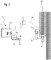
- the control device 4 is also connected to a harvesting vehicle 9 by means of a wireless data connection 8 in addition to its connection to the compaction machines 3 , 5 .
- the harvesting vehicle 9 is designed here in the form of a forage harvester, configured in the example shown to chop corn plants 24 in a field.
- the chopped corn plants 24 then form the harvested crop 2 , which is conveyed directly from the harvesting vehicle 9 to a transport vehicle 25 , which is then driven to the silo 1 by means of a transport vehicle 23 .
- There the trolley 25 is emptied at the delivery point 18 .
- connection of the control device 4 both with the compaction machines 3, 5, of which in figure 2 Only the first compacting machine 3 is shown in simplified form, as well as with the harvesting vehicle 9 has the particular advantage that silo data from the silo 1 can directly influence the operating parameters of the harvesting vehicle 9 .
- the control device 4 can transmit information to the harvesting vehicle 9 , from which, for example, a machine operator of the harvesting vehicle 9 can derive actions for further operation of the harvest. It is also conceivable that the control device 4 acts directly on at least one operating parameter of the harvesting vehicle 9 via the data connection 8 .
Landscapes
- Life Sciences & Earth Sciences (AREA)
- Engineering & Computer Science (AREA)
- Environmental Sciences (AREA)
- General Physics & Mathematics (AREA)
- Aviation & Aerospace Engineering (AREA)
- Radar, Positioning & Navigation (AREA)
- Remote Sensing (AREA)
- Physics & Mathematics (AREA)
- Automation & Control Theory (AREA)
- Soil Sciences (AREA)
- Mechanical Engineering (AREA)
- Management, Administration, Business Operations System, And Electronic Commerce (AREA)
- Filling Or Emptying Of Bunkers, Hoppers, And Tanks (AREA)
Claims (13)
- Procédé de remplissage d'un silo (1) avec du produit récolté à stocker (2), en particulier d'un silo plat avec du maïs haché, comprenant les étapes de procédé suivantes :a) le produit récolté à stocker (2) est réparti dans le silo (1),b) le produit récolté (2) se trouvant dans le silo (1) est parcouru en continu au moyen d'au moins une machine de compactage (3, 5) au moins pour la durée d'un intervalle de temps de compactage, au moins un poids de la machine de compactage (3, 5) agissant sur le produit récolté (2),c) le produit récolté (2) est compacté au moyen de l'action du poids de la machine de compactage (3, 5),caractérisé par
l'étape de procédé suivante :
d) au moins à l'intérieur de l'intervalle de temps de compactage, la machine de compactage (3, 5) est exploitée de façon autonome, la machine de compactage (3, 5) étant commandée au moyen d'au moins un équipement de commande (4), la machine de compactage agissant de façon entièrement autonome sans intervention d'une faculté d'entendement humaine, l'équipement de commande (4) commandant la machine de compactage (3, 5) en fonction d'au moins un paramètre de silo déterminé, à savoir d'une hauteur de silo instantanée (6) et/ou d'un paramètre de produit du produit récolté (2), et modifie une capacité de compactage de la machine de compactage (3, 5) en fonction d'un volume de pores du produit récolté (2). - Procédé selon la revendication 1, caractérisé en ce que le produit récolté (2) est compacté au moyen d'une pluralité, en particulier au moyen de deux, de machines de compactage fonctionnant de manière simultanée et autonome (3, 5) qui sont commandées de préférence au moyen du même équipement de commande (4).
- Procédé selon la revendication 2, caractérisé en ce que les machines de compactage (3, 5) transmettent respectivement des données de travail, en particulier des données de capteur et/ou des données de déplacement, à l'équipement de commande (4), l'équipement de commande (4) permettant de coordonner des séquences de travail des machines de compactage (3, 5), en particulier leurs itinéraires (17), en fonction des données de travail transmises.
- Procédé selon la revendication 2 ou 3, caractérisé en ce qu'une des machines de compactage (3) fait l'objet, par rapport aux autres machines de compactage (5), d'un traitement avantageux de la part de l'équipement de commande (4), de façon qu'en cas de conflit entre des séquences de travail des machines de compactage (3, 5), la séquence de travail de la machine de compactage avantagée (3) ait priorité sur les séquences de travail des machines de compactage désavantagées (5), en particulier de façon qu'en cas de conflit, une séquence de travail d'une machine de compactage désavantagée respective (5) soit interrompue au moins temporairement en faveur de la séquence de travail de la machine de compactage avantagée (3).
- Procédé selon une des revendications 1 à 4, la machine de compactage (3, 5) comprenant au moins un capteur pour déterminer au moins un paramètre de produit du produit récolté (2), en particulier pour déterminer- un comportement de retour élastique du produit récolté (2),- une densité du produit récolté (2),- un volume de pores du produit récolté (2),- une teneur en eau du produit récolté (2),- une masse sèche du produit récolté (2) et/ou- une grosseur particulaire moyenne du produit récolté (2),caractérisé en ce qu'au moins un paramètre de produit du produit récolté (2) est déterminé au moyen de la machine de compactage (3, 5) et transmis à l'équipement de commande (4).
- Procédé selon la revendication 5, caractérisé en ce que, sur la base d'au moins un paramètre de produit, l'équipement de commande (4) détermine un besoin de compactage du produit récolté à compacter (2) et, de préférence, estime l'intervalle de temps de compactage en conséquence.
- Procédé selon une des revendications 1 à 6, l'équipement de commande (4) comportant une liaison de données (8) avec au moins un véhicule de récolte (9) avec lequel le produit récolté (2) est produit, caractérisé en ce que, en fonction d'au moins un paramètre de silo, en particulier d'une hauteur de silo instantanée (6) et/ou d'un paramètre de produit, l'équipement de commande (4) envoie au moins une information à un conducteur de machine d'un véhicule de récolte (9), de préférence modifie directement au moins un paramètre d'exploitation du véhicule de récolte (9), en particulier sa vitesse de travail et/ou une grosseur particulaire à obtenir du produit récolté (2).
- Procédé selon la revendication 7, caractérisé en ce que, en fonction d'une durée de compactage nécessaire à la machine de compactage (3, 5) pour atteindre un résultat de compactage prédéfini d'une couche de produit récolté respectif (10) du silo (1), l'équipement de commande (4) transmet des données au véhicule de récolte (9), de préférence l'équipement de commande (4) agissant au moins indirectement sur une adaptation de la vitesse de travail du véhicule de récolte (9).
- Procédé selon une des revendications 1 à 8, caractérisé en ce que la machine de compactage (3, 5) répartit dans le silo (1) de façon autonome du produit récolté (2) déjà livré mais encore non compacté, de façon qu'une couche de produit récolté non compactée (10) se forme, la machine de compactage (3, 5) commençant automatiquement à compacter la couche de produit récolté non compactée (10) après atteinte d'une hauteur de couche déterminée (11).
- Procédé selon la revendication 9, caractérisé en ce que la hauteur de couche (11) d'une couche de produit récolté respective (10) est commandée en fonction d'au moins un paramètre de produit, en particulier d'une teneur en eau du produit récolté (2) et/ou d'une grosseur particulaire moyenne du produit récolté (2).
- Procédé selon la revendication 9 ou 10, la machine de compactage (3, 5) comportant au moins un équipement de répartition (12), de préférence en forme de lame, caractérisé en ce que l'équipement de commande (4) commande une position de travail de l'équipement de répartition (12), en particulier en fonction d'une hauteur de couche à atteindre (11) de la couche de produit récolté respective (10).
- Procédé selon une des revendications 9 à 11, caractérisé en ce que, en fonction d'au moins un paramètre de produit, en particulier en fonction d'une teneur en eau du produit récolté (2) et/ou d'une grosseur particulaire moyenne du produit récolté (2), la machine de compactage (3, 5) associe de façon autonome du produit récolté à répartir (2) à une couche de produit récolté (10) encore à réaliser ou déjà en cours de réalisation, de préférence la machine de compactage (3, 5) effectuant une mise en couches du silo (1) de façon qu'une hauteur d'empilage du produit récolté respectif (2) dans le silo (1) soit réalisée de manière proportionnelle à la teneur en eau et/ou de manière inversement proportionnelle à la grosseur particulaire moyenne de produit récolté (2).
- Procédé selon une des revendications 2 à 4 en combinaison avec une des revendications 9 à 12, caractérisé en ce qu'au moins une machine de compactage (3) remplit exclusivement une fonction de répartition de produit récolté à répartir (2) et au moins une autre machine de compactage (5) remplit exclusivement une fonction de compactage, de préférence la au moins une machine de compactage (3) remplissant la fonction de répartition faisant l'objet d'un traitement désavantageux de la part de l'équipement de commande (4) par rapport à la au moins une machine de compactage (5) remplissant la fonction de compactage.
Applications Claiming Priority (1)
| Application Number | Priority Date | Filing Date | Title |
|---|---|---|---|
| DE102017110471.2A DE102017110471A1 (de) | 2017-05-15 | 2017-05-15 | Verfahren zum Verdichten von in einem Silo befindlichem Erntegut |
Publications (3)
| Publication Number | Publication Date |
|---|---|
| EP3403487A1 EP3403487A1 (fr) | 2018-11-21 |
| EP3403487B1 EP3403487B1 (fr) | 2019-12-04 |
| EP3403487B2 true EP3403487B2 (fr) | 2022-11-16 |
Family
ID=61581077
Family Applications (1)
| Application Number | Title | Priority Date | Filing Date |
|---|---|---|---|
| EP18160386.1A Active EP3403487B2 (fr) | 2017-05-15 | 2018-03-07 | Procédé de compactage d'un produit récolté se trouvant dans un silo |
Country Status (2)
| Country | Link |
|---|---|
| EP (1) | EP3403487B2 (fr) |
| DE (1) | DE102017110471A1 (fr) |
Families Citing this family (8)
| Publication number | Priority date | Publication date | Assignee | Title |
|---|---|---|---|---|
| DE102020204475A1 (de) | 2020-04-07 | 2021-10-07 | Deere & Company | Verfahren und Anordnung zur Herstellung von Silage |
| DE102020110297A1 (de) | 2020-04-15 | 2021-10-21 | Deere & Company | Verfahren, Steuereinrichtung und Verdichtungsfahrzeug zur Verdichtung von Erntegut in einem Silo |
| DE102020206120A1 (de) | 2020-04-17 | 2021-10-21 | Deere & Company | Verfahren zur Unterstützung einer verdichtungsgerechten Erntegutverteilung in einem Flachsilo |
| EP3895521B1 (fr) * | 2020-04-17 | 2023-03-15 | Deere & Company | Procédé de commande de la distribution et du compactage du produit de récolte dans un silo plat |
| DE102021117470A1 (de) | 2020-07-21 | 2022-01-27 | Deere & Company | Verfahren und Anordnung zur Kontrolle eines Betriebsparameters eines Feldhäckslers |
| DE102020129359A1 (de) | 2020-11-06 | 2022-05-12 | Deere & Company | Sensoranordnung zur Erfassung der Dichte von Erntegut in einem Silo und damit ausgestattetes Verdichtungsfahrzeug |
| DE102021120329A1 (de) | 2021-08-04 | 2023-02-09 | Deere & Company | Einlagerung von Erntegut in einem Silo |
| IT202100021326A1 (it) * | 2021-08-05 | 2023-02-05 | Cnh Ind Italia Spa | Veicolo migliorato per compattare un prodotto da stoccare in un silo |
Citations (5)
| Publication number | Priority date | Publication date | Assignee | Title |
|---|---|---|---|---|
| US5471391A (en) † | 1993-12-08 | 1995-11-28 | Caterpillar Inc. | Method and apparatus for operating compacting machinery relative to a work site |
| US6112143A (en) † | 1998-08-06 | 2000-08-29 | Caterpillar Inc. | Method and apparatus for establishing a perimeter defining an area to be traversed by a mobile machine |
| DE10317160A1 (de) † | 2003-04-14 | 2004-11-18 | Wacker Construction Equipment Ag | System und Verfahren zur automatisierten Bodenverdichtung |
| US20070129869A1 (en) † | 2005-12-06 | 2007-06-07 | Caterpillar Inc. | System for autonomous cooperative control of multiple machines |
| WO2016209118A1 (fr) † | 2015-06-26 | 2016-12-29 | Сергей Валерьевич ЗЛОЧЕВСКИЙ | Procédé de préparation d'aliments pour animaux |
Family Cites Families (7)
| Publication number | Priority date | Publication date | Assignee | Title |
|---|---|---|---|---|
| DE19537085A1 (de) | 1995-10-05 | 1997-04-10 | Stotz Gmbh & Co Kg M | Silobeschickungsvorrichtung |
| EP1795884A1 (fr) | 2005-12-07 | 2007-06-13 | Leibnitz-Inst. für Agrartechnik-Potsdam-Bornim e.V | Procédé et moyen de mesure de la densité d'un produit agricole |
| DE102007053610A1 (de) | 2007-11-08 | 2009-05-14 | Humboldt-Universität Zu Berlin | Verfahren zur Bestimmung der Verdichtung in landwirtschaftlichen Horizontalsilos |
| DE102008063852A1 (de) | 2008-12-19 | 2010-07-08 | Claas Selbstfahrende Erntemaschinen Gmbh | Verfahren zur Steuerung der Verdichtung eines landwirtschaftlichen Guts in einem Fahr- bzw. Flachsilo und Verdichtungsfahrzeug |
| DE202010006957U1 (de) * | 2010-05-19 | 2010-08-05 | Stehr, Jürgen | Silageverdichter |
| DE102011117860A1 (de) | 2011-11-08 | 2013-05-08 | Claas Selbstfahrende Erntemaschinen Gmbh | Verfahren und System zum Ernten und Silieren von Futtermaterial |
| WO2017026080A1 (fr) * | 2015-08-13 | 2017-02-16 | ヤンマー株式会社 | Procédé de conception d'itinéraire pour véhicule autonome |
-
2017
- 2017-05-15 DE DE102017110471.2A patent/DE102017110471A1/de active Pending
-
2018
- 2018-03-07 EP EP18160386.1A patent/EP3403487B2/fr active Active
Patent Citations (6)
| Publication number | Priority date | Publication date | Assignee | Title |
|---|---|---|---|---|
| US5471391A (en) † | 1993-12-08 | 1995-11-28 | Caterpillar Inc. | Method and apparatus for operating compacting machinery relative to a work site |
| US6112143A (en) † | 1998-08-06 | 2000-08-29 | Caterpillar Inc. | Method and apparatus for establishing a perimeter defining an area to be traversed by a mobile machine |
| DE10317160A1 (de) † | 2003-04-14 | 2004-11-18 | Wacker Construction Equipment Ag | System und Verfahren zur automatisierten Bodenverdichtung |
| US20070129869A1 (en) † | 2005-12-06 | 2007-06-07 | Caterpillar Inc. | System for autonomous cooperative control of multiple machines |
| WO2016209118A1 (fr) † | 2015-06-26 | 2016-12-29 | Сергей Валерьевич ЗЛОЧЕВСКИЙ | Procédé de préparation d'aliments pour animaux |
| DE112016000130T5 (de) † | 2015-06-26 | 2017-07-13 | Sergey Valerevich Zlochevskiy | System für die Zubereitung von Tierfutter |
Non-Patent Citations (4)
| Title |
|---|
| ANONYMOUS: "The future of autonomous compaction has already begun", WORLD HIGHWAYS, 1 December 2016 (2016-12-01), pages 59 - 61 † |
| GERIGHAUSEN: "Silieren: Drei Fehler, die sich immer rächen", TOP AGRAR, 1 April 2004 (2004-04-01), pages 104 - 107 † |
| T. HOFFMANN ET AL.: "Radiometrie density measurement for silage compaction in bunker silos", AGRIC ENG INT: CIGR JOURNAL, vol. 15, no. 3, September 2013 (2013-09-01), pages 191 - 197 † |
| TÖLLE RAINER, HÄBLER JAN, HAHN JÜRGEN: "Gute Verdichtung im Silo - der Schlüssel zu hoher Konservatqualität", BORNIMER AGRARTECHNISCHE BERICHTE, INSTITUT F�R AGRARTECHNIK BORNIM E.V., POTSDAM-BORNIM, vol. 68, 1 January 2009 (2009-01-01), Potsdam-Bornim, pages 25 - 34, ISSN: 0947-7314 † |
Also Published As
| Publication number | Publication date |
|---|---|
| EP3403487A1 (fr) | 2018-11-21 |
| EP3403487B1 (fr) | 2019-12-04 |
| DE102017110471A1 (de) | 2018-11-15 |
Similar Documents
| Publication | Publication Date | Title |
|---|---|---|
| EP3403487B2 (fr) | Procédé de compactage d'un produit récolté se trouvant dans un silo | |
| EP3400774B1 (fr) | Procédé d'élaboration d'un processus de récolte agricole | |
| EP3563667B1 (fr) | Procédé de distribution de produit de récolte | |
| EP1977640B1 (fr) | Moissonneuse agricole automobile dotée d'un dispositif de transbordement réglable | |
| DE102018111077A1 (de) | Mähdrescher sowie Verfahren zum Betreiben eines Mähdreschers | |
| EP2936969B1 (fr) | Combinaison d'un véhicule de traction et d'une moissonneuse tirée par celui-ci | |
| EP2591659B1 (fr) | Procédé et control destinés à récolter et ensiler des matières fourragères | |
| EP2995191A1 (fr) | Procédé de commande d'un processus de transbordement | |
| EP3533315B1 (fr) | Récolteuse-hacheuse-chargeuse de fourrage et procédé de fonctionnement d'une récolteuse-hacheuse-chargeuse de fourrage | |
| EP1051898A2 (fr) | Dispositif pour régler la vitesse d'avance d'une récolteuse utilisant la logique floue | |
| DE102008027906A1 (de) | Landwirtschaftliche Erntemaschine | |
| DE102008032418A1 (de) | Landwirtschaftlicher Maschinenverband | |
| EP3895520A1 (fr) | Procédé, dispositif de commande et véhicule de compactage destinés au compactage de la récolte dans un silo | |
| EP3095315A1 (fr) | Procede et dispositif de commande destines au fonctionnement d'un chargeur agricole | |
| EP3895521B1 (fr) | Procédé de commande de la distribution et du compactage du produit de récolte dans un silo plat | |
| DE102022101895A1 (de) | Selbstfahrender Feldhäcksler sowie Verfahren zum Betreiben eines selbstfahrenden Feldhäckslers | |
| EP3569458B1 (fr) | Procédé de fonctionnement d'un système de freinage d'un tracteur agricole, système de freinage pour un tracteur agricole ainsi que tracteur agricole | |
| AT17986U1 (de) | Verfahren zum Betreiben eines landwirtschaftlichen Ladewagens und landwirtschaftlicher Ladewagen | |
| EP3498079A1 (fr) | Procédé de remplissage d'un silos de produit de récolte et véhicule de distribution | |
| EP4074160B1 (fr) | Procédé de réglage d'un niveau de remplissage dans un récipient | |
| EP2857919B1 (fr) | Système de commande du fonctionnement d'un véhicule utilitaire agricole | |
| EP2108248B1 (fr) | Ramasseuse-hacheuse et dispositif d'introduction pour une ramasseuse-hacheuse | |
| EP4268560A1 (fr) | Machine de travail agricole autonome | |
| DE102023129476A1 (de) | Management der leistungsumschaltung für fahrerassistenz | |
| DE102021119684A1 (de) | Verfahren zur Verdichtung eines Erntegutes |
Legal Events
| Date | Code | Title | Description |
|---|---|---|---|
| PUAI | Public reference made under article 153(3) epc to a published international application that has entered the european phase |
Free format text: ORIGINAL CODE: 0009012 |
|
| STAA | Information on the status of an ep patent application or granted ep patent |
Free format text: STATUS: THE APPLICATION HAS BEEN PUBLISHED |
|
| AK | Designated contracting states |
Kind code of ref document: A1 Designated state(s): AL AT BE BG CH CY CZ DE DK EE ES FI FR GB GR HR HU IE IS IT LI LT LU LV MC MK MT NL NO PL PT RO RS SE SI SK SM TR |
|
| AX | Request for extension of the european patent |
Extension state: BA ME |
|
| STAA | Information on the status of an ep patent application or granted ep patent |
Free format text: STATUS: REQUEST FOR EXAMINATION WAS MADE |
|
| 17P | Request for examination filed |
Effective date: 20190521 |
|
| RBV | Designated contracting states (corrected) |
Designated state(s): AL AT BE BG CH CY CZ DE DK EE ES FI FR GB GR HR HU IE IS IT LI LT LU LV MC MK MT NL NO PL PT RO RS SE SI SK SM TR |
|
| RIC1 | Information provided on ipc code assigned before grant |
Ipc: G05D 1/02 20060101ALI20190704BHEP Ipc: A01F 25/16 20060101AFI20190704BHEP Ipc: A01F 25/18 20060101ALI20190704BHEP Ipc: A01B 69/00 20060101ALI20190704BHEP |
|
| GRAP | Despatch of communication of intention to grant a patent |
Free format text: ORIGINAL CODE: EPIDOSNIGR1 |
|
| STAA | Information on the status of an ep patent application or granted ep patent |
Free format text: STATUS: GRANT OF PATENT IS INTENDED |
|
| INTG | Intention to grant announced |
Effective date: 20190906 |
|
| GRAS | Grant fee paid |
Free format text: ORIGINAL CODE: EPIDOSNIGR3 |
|
| GRAA | (expected) grant |
Free format text: ORIGINAL CODE: 0009210 |
|
| STAA | Information on the status of an ep patent application or granted ep patent |
Free format text: STATUS: THE PATENT HAS BEEN GRANTED |
|
| AK | Designated contracting states |
Kind code of ref document: B1 Designated state(s): AL AT BE BG CH CY CZ DE DK EE ES FI FR GB GR HR HU IE IS IT LI LT LU LV MC MK MT NL NO PL PT RO RS SE SI SK SM TR |
|
| REG | Reference to a national code |
Ref country code: GB Ref legal event code: FG4D Free format text: NOT ENGLISH |
|
| REG | Reference to a national code |
Ref country code: CH Ref legal event code: EP |
|
| REG | Reference to a national code |
Ref country code: AT Ref legal event code: REF Ref document number: 1208234 Country of ref document: AT Kind code of ref document: T Effective date: 20191215 |
|
| REG | Reference to a national code |
Ref country code: DE Ref legal event code: R096 Ref document number: 502018000455 Country of ref document: DE |
|
| REG | Reference to a national code |
Ref country code: IE Ref legal event code: FG4D Free format text: LANGUAGE OF EP DOCUMENT: GERMAN |
|
| REG | Reference to a national code |
Ref country code: NL Ref legal event code: MP Effective date: 20191204 |
|
| REG | Reference to a national code |
Ref country code: LT Ref legal event code: MG4D |
|
| PG25 | Lapsed in a contracting state [announced via postgrant information from national office to epo] |
Ref country code: LV Free format text: LAPSE BECAUSE OF FAILURE TO SUBMIT A TRANSLATION OF THE DESCRIPTION OR TO PAY THE FEE WITHIN THE PRESCRIBED TIME-LIMIT Effective date: 20191204 Ref country code: SE Free format text: LAPSE BECAUSE OF FAILURE TO SUBMIT A TRANSLATION OF THE DESCRIPTION OR TO PAY THE FEE WITHIN THE PRESCRIBED TIME-LIMIT Effective date: 20191204 Ref country code: LT Free format text: LAPSE BECAUSE OF FAILURE TO SUBMIT A TRANSLATION OF THE DESCRIPTION OR TO PAY THE FEE WITHIN THE PRESCRIBED TIME-LIMIT Effective date: 20191204 Ref country code: NO Free format text: LAPSE BECAUSE OF FAILURE TO SUBMIT A TRANSLATION OF THE DESCRIPTION OR TO PAY THE FEE WITHIN THE PRESCRIBED TIME-LIMIT Effective date: 20200304 Ref country code: GR Free format text: LAPSE BECAUSE OF FAILURE TO SUBMIT A TRANSLATION OF THE DESCRIPTION OR TO PAY THE FEE WITHIN THE PRESCRIBED TIME-LIMIT Effective date: 20200305 Ref country code: BG Free format text: LAPSE BECAUSE OF FAILURE TO SUBMIT A TRANSLATION OF THE DESCRIPTION OR TO PAY THE FEE WITHIN THE PRESCRIBED TIME-LIMIT Effective date: 20200304 Ref country code: FI Free format text: LAPSE BECAUSE OF FAILURE TO SUBMIT A TRANSLATION OF THE DESCRIPTION OR TO PAY THE FEE WITHIN THE PRESCRIBED TIME-LIMIT Effective date: 20191204 |
|
| PG25 | Lapsed in a contracting state [announced via postgrant information from national office to epo] |
Ref country code: HR Free format text: LAPSE BECAUSE OF FAILURE TO SUBMIT A TRANSLATION OF THE DESCRIPTION OR TO PAY THE FEE WITHIN THE PRESCRIBED TIME-LIMIT Effective date: 20191204 Ref country code: RS Free format text: LAPSE BECAUSE OF FAILURE TO SUBMIT A TRANSLATION OF THE DESCRIPTION OR TO PAY THE FEE WITHIN THE PRESCRIBED TIME-LIMIT Effective date: 20191204 |
|
| PG25 | Lapsed in a contracting state [announced via postgrant information from national office to epo] |
Ref country code: AL Free format text: LAPSE BECAUSE OF FAILURE TO SUBMIT A TRANSLATION OF THE DESCRIPTION OR TO PAY THE FEE WITHIN THE PRESCRIBED TIME-LIMIT Effective date: 20191204 |
|
| REG | Reference to a national code |
Ref country code: DE Ref legal event code: R026 Ref document number: 502018000455 Country of ref document: DE |
|
| PG25 | Lapsed in a contracting state [announced via postgrant information from national office to epo] |
Ref country code: RO Free format text: LAPSE BECAUSE OF FAILURE TO SUBMIT A TRANSLATION OF THE DESCRIPTION OR TO PAY THE FEE WITHIN THE PRESCRIBED TIME-LIMIT Effective date: 20191204 Ref country code: CZ Free format text: LAPSE BECAUSE OF FAILURE TO SUBMIT A TRANSLATION OF THE DESCRIPTION OR TO PAY THE FEE WITHIN THE PRESCRIBED TIME-LIMIT Effective date: 20191204 Ref country code: PT Free format text: LAPSE BECAUSE OF FAILURE TO SUBMIT A TRANSLATION OF THE DESCRIPTION OR TO PAY THE FEE WITHIN THE PRESCRIBED TIME-LIMIT Effective date: 20200429 Ref country code: EE Free format text: LAPSE BECAUSE OF FAILURE TO SUBMIT A TRANSLATION OF THE DESCRIPTION OR TO PAY THE FEE WITHIN THE PRESCRIBED TIME-LIMIT Effective date: 20191204 Ref country code: NL Free format text: LAPSE BECAUSE OF FAILURE TO SUBMIT A TRANSLATION OF THE DESCRIPTION OR TO PAY THE FEE WITHIN THE PRESCRIBED TIME-LIMIT Effective date: 20191204 Ref country code: ES Free format text: LAPSE BECAUSE OF FAILURE TO SUBMIT A TRANSLATION OF THE DESCRIPTION OR TO PAY THE FEE WITHIN THE PRESCRIBED TIME-LIMIT Effective date: 20191204 |
|
| PLBI | Opposition filed |
Free format text: ORIGINAL CODE: 0009260 |
|
| PG25 | Lapsed in a contracting state [announced via postgrant information from national office to epo] |
Ref country code: SK Free format text: LAPSE BECAUSE OF FAILURE TO SUBMIT A TRANSLATION OF THE DESCRIPTION OR TO PAY THE FEE WITHIN THE PRESCRIBED TIME-LIMIT Effective date: 20191204 Ref country code: IS Free format text: LAPSE BECAUSE OF FAILURE TO SUBMIT A TRANSLATION OF THE DESCRIPTION OR TO PAY THE FEE WITHIN THE PRESCRIBED TIME-LIMIT Effective date: 20200404 Ref country code: SM Free format text: LAPSE BECAUSE OF FAILURE TO SUBMIT A TRANSLATION OF THE DESCRIPTION OR TO PAY THE FEE WITHIN THE PRESCRIBED TIME-LIMIT Effective date: 20191204 |
|
| 26 | Opposition filed |
Opponent name: DEERE & COMPANY Effective date: 20200729 |
|
| PLAX | Notice of opposition and request to file observation + time limit sent |
Free format text: ORIGINAL CODE: EPIDOSNOBS2 |
|
| PG25 | Lapsed in a contracting state [announced via postgrant information from national office to epo] |
Ref country code: MC Free format text: LAPSE BECAUSE OF FAILURE TO SUBMIT A TRANSLATION OF THE DESCRIPTION OR TO PAY THE FEE WITHIN THE PRESCRIBED TIME-LIMIT Effective date: 20191204 Ref country code: DK Free format text: LAPSE BECAUSE OF FAILURE TO SUBMIT A TRANSLATION OF THE DESCRIPTION OR TO PAY THE FEE WITHIN THE PRESCRIBED TIME-LIMIT Effective date: 20191204 |
|
| PG25 | Lapsed in a contracting state [announced via postgrant information from national office to epo] |
Ref country code: PL Free format text: LAPSE BECAUSE OF FAILURE TO SUBMIT A TRANSLATION OF THE DESCRIPTION OR TO PAY THE FEE WITHIN THE PRESCRIBED TIME-LIMIT Effective date: 20191204 Ref country code: SI Free format text: LAPSE BECAUSE OF FAILURE TO SUBMIT A TRANSLATION OF THE DESCRIPTION OR TO PAY THE FEE WITHIN THE PRESCRIBED TIME-LIMIT Effective date: 20191204 |
|
| PLBB | Reply of patent proprietor to notice(s) of opposition received |
Free format text: ORIGINAL CODE: EPIDOSNOBS3 |
|
| PLAB | Opposition data, opponent's data or that of the opponent's representative modified |
Free format text: ORIGINAL CODE: 0009299OPPO |
|
| REG | Reference to a national code |
Ref country code: BE Ref legal event code: MM Effective date: 20200331 |
|
| PG25 | Lapsed in a contracting state [announced via postgrant information from national office to epo] |
Ref country code: LU Free format text: LAPSE BECAUSE OF NON-PAYMENT OF DUE FEES Effective date: 20200307 |
|
| R26 | Opposition filed (corrected) |
Opponent name: DEERE & COMPANY/JOHN DEERE GMBH & CO. KG Effective date: 20200729 |
|
| PG25 | Lapsed in a contracting state [announced via postgrant information from national office to epo] |
Ref country code: IT Free format text: LAPSE BECAUSE OF FAILURE TO SUBMIT A TRANSLATION OF THE DESCRIPTION OR TO PAY THE FEE WITHIN THE PRESCRIBED TIME-LIMIT Effective date: 20191204 Ref country code: IE Free format text: LAPSE BECAUSE OF NON-PAYMENT OF DUE FEES Effective date: 20200307 Ref country code: FR Free format text: LAPSE BECAUSE OF NON-PAYMENT OF DUE FEES Effective date: 20200331 |
|
| PG25 | Lapsed in a contracting state [announced via postgrant information from national office to epo] |
Ref country code: BE Free format text: LAPSE BECAUSE OF NON-PAYMENT OF DUE FEES Effective date: 20200331 |
|
| REG | Reference to a national code |
Ref country code: CH Ref legal event code: PL |
|
| PG25 | Lapsed in a contracting state [announced via postgrant information from national office to epo] |
Ref country code: LI Free format text: LAPSE BECAUSE OF NON-PAYMENT OF DUE FEES Effective date: 20210331 Ref country code: CH Free format text: LAPSE BECAUSE OF NON-PAYMENT OF DUE FEES Effective date: 20210331 |
|
| PG25 | Lapsed in a contracting state [announced via postgrant information from national office to epo] |
Ref country code: TR Free format text: LAPSE BECAUSE OF FAILURE TO SUBMIT A TRANSLATION OF THE DESCRIPTION OR TO PAY THE FEE WITHIN THE PRESCRIBED TIME-LIMIT Effective date: 20191204 Ref country code: MT Free format text: LAPSE BECAUSE OF FAILURE TO SUBMIT A TRANSLATION OF THE DESCRIPTION OR TO PAY THE FEE WITHIN THE PRESCRIBED TIME-LIMIT Effective date: 20191204 Ref country code: CY Free format text: LAPSE BECAUSE OF FAILURE TO SUBMIT A TRANSLATION OF THE DESCRIPTION OR TO PAY THE FEE WITHIN THE PRESCRIBED TIME-LIMIT Effective date: 20191204 |
|
| PG25 | Lapsed in a contracting state [announced via postgrant information from national office to epo] |
Ref country code: MK Free format text: LAPSE BECAUSE OF FAILURE TO SUBMIT A TRANSLATION OF THE DESCRIPTION OR TO PAY THE FEE WITHIN THE PRESCRIBED TIME-LIMIT Effective date: 20191204 |
|
| PUAH | Patent maintained in amended form |
Free format text: ORIGINAL CODE: 0009272 |
|
| STAA | Information on the status of an ep patent application or granted ep patent |
Free format text: STATUS: PATENT MAINTAINED AS AMENDED |
|
| 27A | Patent maintained in amended form |
Effective date: 20221116 |
|
| AK | Designated contracting states |
Kind code of ref document: B2 Designated state(s): AL AT BE BG CH CY CZ DE DK EE ES FI FR GB GR HR HU IE IS IT LI LT LU LV MC MK MT NL NO PL PT RO RS SE SI SK SM TR |
|
| REG | Reference to a national code |
Ref country code: DE Ref legal event code: R102 Ref document number: 502018000455 Country of ref document: DE |
|
| GBPC | Gb: european patent ceased through non-payment of renewal fee |
Effective date: 20220307 |
|
| PG25 | Lapsed in a contracting state [announced via postgrant information from national office to epo] |
Ref country code: GB Free format text: LAPSE BECAUSE OF NON-PAYMENT OF DUE FEES Effective date: 20220307 |
|
| P01 | Opt-out of the competence of the unified patent court (upc) registered |
Effective date: 20230516 |
|
| PGFP | Annual fee paid to national office [announced via postgrant information from national office to epo] |
Ref country code: DE Payment date: 20240320 Year of fee payment: 7 |
|
| REG | Reference to a national code |
Ref country code: AT Ref legal event code: MM01 Ref document number: 1208234 Country of ref document: AT Kind code of ref document: T Effective date: 20230307 |