EP3402997B1 - Brake caliper guide pin low pressure isolation damper - Google Patents
Brake caliper guide pin low pressure isolation damper Download PDFInfo
- Publication number
- EP3402997B1 EP3402997B1 EP17738766.9A EP17738766A EP3402997B1 EP 3402997 B1 EP3402997 B1 EP 3402997B1 EP 17738766 A EP17738766 A EP 17738766A EP 3402997 B1 EP3402997 B1 EP 3402997B1
- Authority
- EP
- European Patent Office
- Prior art keywords
- stem
- disc brake
- brake assembly
- damper
- interior surface
- Prior art date
- Legal status (The legal status is an assumption and is not a legal conclusion. Google has not performed a legal analysis and makes no representation as to the accuracy of the status listed.)
- Active
Links
Images


Classifications
-
- F—MECHANICAL ENGINEERING; LIGHTING; HEATING; WEAPONS; BLASTING
- F16—ENGINEERING ELEMENTS AND UNITS; GENERAL MEASURES FOR PRODUCING AND MAINTAINING EFFECTIVE FUNCTIONING OF MACHINES OR INSTALLATIONS; THERMAL INSULATION IN GENERAL
- F16D—COUPLINGS FOR TRANSMITTING ROTATION; CLUTCHES; BRAKES
- F16D65/00—Parts or details
- F16D65/0006—Noise or vibration control
-
- F—MECHANICAL ENGINEERING; LIGHTING; HEATING; WEAPONS; BLASTING
- F16—ENGINEERING ELEMENTS AND UNITS; GENERAL MEASURES FOR PRODUCING AND MAINTAINING EFFECTIVE FUNCTIONING OF MACHINES OR INSTALLATIONS; THERMAL INSULATION IN GENERAL
- F16D—COUPLINGS FOR TRANSMITTING ROTATION; CLUTCHES; BRAKES
- F16D55/00—Brakes with substantially-radial braking surfaces pressed together in axial direction, e.g. disc brakes
- F16D55/02—Brakes with substantially-radial braking surfaces pressed together in axial direction, e.g. disc brakes with axially-movable discs or pads pressed against axially-located rotating members
- F16D55/22—Brakes with substantially-radial braking surfaces pressed together in axial direction, e.g. disc brakes with axially-movable discs or pads pressed against axially-located rotating members by clamping an axially-located rotating disc between movable braking members, e.g. movable brake discs or brake pads
- F16D55/224—Brakes with substantially-radial braking surfaces pressed together in axial direction, e.g. disc brakes with axially-movable discs or pads pressed against axially-located rotating members by clamping an axially-located rotating disc between movable braking members, e.g. movable brake discs or brake pads with a common actuating member for the braking members
- F16D55/225—Brakes with substantially-radial braking surfaces pressed together in axial direction, e.g. disc brakes with axially-movable discs or pads pressed against axially-located rotating members by clamping an axially-located rotating disc between movable braking members, e.g. movable brake discs or brake pads with a common actuating member for the braking members the braking members being brake pads
- F16D55/226—Brakes with substantially-radial braking surfaces pressed together in axial direction, e.g. disc brakes with axially-movable discs or pads pressed against axially-located rotating members by clamping an axially-located rotating disc between movable braking members, e.g. movable brake discs or brake pads with a common actuating member for the braking members the braking members being brake pads in which the common actuating member is moved axially, e.g. floating caliper disc brakes
- F16D55/2265—Brakes with substantially-radial braking surfaces pressed together in axial direction, e.g. disc brakes with axially-movable discs or pads pressed against axially-located rotating members by clamping an axially-located rotating disc between movable braking members, e.g. movable brake discs or brake pads with a common actuating member for the braking members the braking members being brake pads in which the common actuating member is moved axially, e.g. floating caliper disc brakes the axial movement being guided by one or more pins engaging bores in the brake support or the brake housing
- F16D55/22655—Constructional details of guide pins
-
- F—MECHANICAL ENGINEERING; LIGHTING; HEATING; WEAPONS; BLASTING
- F16—ENGINEERING ELEMENTS AND UNITS; GENERAL MEASURES FOR PRODUCING AND MAINTAINING EFFECTIVE FUNCTIONING OF MACHINES OR INSTALLATIONS; THERMAL INSULATION IN GENERAL
- F16D—COUPLINGS FOR TRANSMITTING ROTATION; CLUTCHES; BRAKES
- F16D55/00—Brakes with substantially-radial braking surfaces pressed together in axial direction, e.g. disc brakes
- F16D55/02—Brakes with substantially-radial braking surfaces pressed together in axial direction, e.g. disc brakes with axially-movable discs or pads pressed against axially-located rotating members
- F16D55/22—Brakes with substantially-radial braking surfaces pressed together in axial direction, e.g. disc brakes with axially-movable discs or pads pressed against axially-located rotating members by clamping an axially-located rotating disc between movable braking members, e.g. movable brake discs or brake pads
- F16D55/224—Brakes with substantially-radial braking surfaces pressed together in axial direction, e.g. disc brakes with axially-movable discs or pads pressed against axially-located rotating members by clamping an axially-located rotating disc between movable braking members, e.g. movable brake discs or brake pads with a common actuating member for the braking members
- F16D55/225—Brakes with substantially-radial braking surfaces pressed together in axial direction, e.g. disc brakes with axially-movable discs or pads pressed against axially-located rotating members by clamping an axially-located rotating disc between movable braking members, e.g. movable brake discs or brake pads with a common actuating member for the braking members the braking members being brake pads
- F16D55/226—Brakes with substantially-radial braking surfaces pressed together in axial direction, e.g. disc brakes with axially-movable discs or pads pressed against axially-located rotating members by clamping an axially-located rotating disc between movable braking members, e.g. movable brake discs or brake pads with a common actuating member for the braking members the braking members being brake pads in which the common actuating member is moved axially, e.g. floating caliper disc brakes
- F16D55/2265—Brakes with substantially-radial braking surfaces pressed together in axial direction, e.g. disc brakes with axially-movable discs or pads pressed against axially-located rotating members by clamping an axially-located rotating disc between movable braking members, e.g. movable brake discs or brake pads with a common actuating member for the braking members the braking members being brake pads in which the common actuating member is moved axially, e.g. floating caliper disc brakes the axial movement being guided by one or more pins engaging bores in the brake support or the brake housing
- F16D55/227—Brakes with substantially-radial braking surfaces pressed together in axial direction, e.g. disc brakes with axially-movable discs or pads pressed against axially-located rotating members by clamping an axially-located rotating disc between movable braking members, e.g. movable brake discs or brake pads with a common actuating member for the braking members the braking members being brake pads in which the common actuating member is moved axially, e.g. floating caliper disc brakes the axial movement being guided by one or more pins engaging bores in the brake support or the brake housing by two or more pins
Definitions
- This invention relates in general to vehicle disc brake assemblies and in particular to a guide pin isolation damper adapted for use in such a vehicle disc brake assembly.
- a typical brake system for an automobile or light truck includes a disc brake assembly for each of the front wheels and either a drum brake assembly or a disc brake assembly for each of the rear wheels.
- the brake assemblies are actuated by hydraulic or pneumatic pressure generated when an operator of the vehicle depresses a brake pedal.
- the structures of these drum brake assemblies and disc brake assemblies, as well as the actuators therefor, are well known in the art.
- Typical disc brake assemblies include a rotor which is secured to the wheel of the vehicle for rotation therewith.
- the rotor includes a pair of opposed friction plates which are selectively engaged by portions of a caliper assembly.
- the caliper is slidably supported on an anchor bracket by guide pins.
- the guide pins are secured to the caliper by guide pin fasteners and extend into bores of the anchor brackets. The guide pins contact the anchor bracket at contact points in the bores and create a contact load on each of the guide pins at the contact points.
- the anchor bracket is attached to a non-rotatable component of the vehicle, such as the vehicle frame.
- the caliper assembly includes a pair of brake shoes which are disposed on opposite sides of the brake rotor.
- the brake shoes are connected to one or more hydraulically or pneumatically actuated pistons for movement between a non-braking position, wherein they are spaced apart from the opposed friction plates of the rotor, and a braking position, wherein they are moved into frictional engagement with the opposed friction plates of the rotor.
- the piston urges the brake shoes from the non-braking position to the braking position so as to frictionally engage the friction plates of the rotor and thereby slow or stop the rotation of the associated wheel of the vehicle.
- the anchor bracket bores have a greater diameter than the guide pins.
- the guide pins have a clearance between an exterior surface of the guide pin and an interior surface of the bore such that the guide pins may move within the bores.
- a damper may be provided on the guide pins to provide a defined point of contact between the guide pins and bores when a brake loading is applied to the disc brake assembly.
- a guide pin with a defined contact point may still contact or strike the interior surface of the bore and produce noise, vibration, or harshness when there is no brake loading or a low pressure brake loading.
- EP 2 914 866 A1 discloses a disc brake assembly that comprises an anchor bracket having a bore formed therein.
- a brake caliper is slidably secured to the anchor bracket and a pair of brake pads is carried by the disc brake assembly.
- a guide pin is adapted to be disposed in the bore of the anchor bracket.
- DE 10 2013 011 469 A1 discloses a disc brake arrangement for a motor vehicle brake system, comprising a brake carrier which has a bore and a guide pin arranged in the bore.
- JP H07 197 962 A discloses a sliding guide mechanism for a caliper comprising a pair of sliding pins that are slidably fitted to pin support holes.
- the caliper is supported by a support bracket.
- the sliding pins are fixed to the support bracket or the caliper.
- the slide pin is in press-contact with an inner surface on the opposite side of the pin support hole.
- JP H11 257 385 A discloses a disc brake comprising an arm part and a sliding pin.
- the sliding pin is relatively movable to a portion where the diameter of a pin hole is large. As a result, the sliding resistance of the sliding pin is reduced, and the caliper slides smoothly.
- This invention relates to a brake caliper guide pin having an isolation damper and configured for use in a vehicle disc brake assembly.
- a disc brake assembly comprises an anchor bracket having at least one bore formed therein; a guide pin configured to be slidably supported in the bore and having a stem; at least one main damper configured to be disposed between the stem and an interior surface of the bore and configured to bias a portion of the stem against the interior surface of the bore depending upon brake loading on the disc brake assembly; and at least one secondary damper configured to be disposed between the stem and the interior surface, wherein the secondary damper is configured to limit a contact between the stem and the interior surface depending upon brake loading on the disc brake assembly.
- the secondary damper has a compression threshold and, when a brake loading exceeds the compression threshold, the isolation damper is compressed.
- the secondary damper has a contact threshold and, when a brake loading exceeds the contact threshold, the secondary damper allows contact between the stem and the interior surface.
- contact between the stem and the interior surface is at a defined contact point.
- the secondary damper has a stiffness, and the stiffness is adjusted to set compression and contact thresholds.
- the secondary damper is opposite the main damper.
- the secondary damper limits contact between the stem and the interior surface during brake loading on the disc brake assembly.
- the secondary damper limits contact between the stem and the interior surface without brake loading on the disc brake assembly.
- the secondary damper holds the main damper against the interior surface.
- the stem contacts the bore at a defined contact point.
- the secondary damper has a lower stiffness than the main damper and the pin and the bore have a common longitudinal axis.
- a further secondary damper is between the stem and the interior surface, wherein the two secondary dampers together limit contact between the stem and the interior surface.
- a brake caliper secured to the guide pin; and inboard and outboard brake shoes supported on the anchor bracket by clips.
- the disc brake assembly may comprise a clearance exists between the stem and the interior surface of the bore when there is no brake loading on the disc brake assembly and as the brake loading increases the secondary damper is compressed until the clearance is closed and a portion of the stem contacts the interior surface.
- the secondary damper does not compress until a compression threshold is exceeded.
- the stem contacts the inner surface at a defined contact point.
- the main damper and the secondary damper are located on opposite longitudinal sides of the stem.
- a further secondary damper between the stem and the interior surface, wherein the two secondary dampers together limit contact between the stem and the interior surface.
- a brake caliper secured to the guide pin; and inboard and outboard brake shoes supported on the anchor bracket by clips.
- An advantage of an embodiment is reduced metal to metal contact between a guide pin and an anchor bracket bore in which the guide pin is inserted.
- FIG. 1 a portion of a vehicle disc brake assembly, indicated generally at 100, with a knuckle, indicated generally at 102.
- the general structure and operation of the disc brake assembly 100 is conventional in the art.
- the disc brake assembly 100 may be as disclosed in U.S. Patent Publication No. 2014/0231191 to Morais et al. .
- the disc brake assembly 100 may be as disclosed in U.S. Patent Publication No. 2014/0231191 to Morais et al. .
- this invention will be described and illustrated in connection with the particular vehicle disc brake assembly disclosed herein, it will be appreciated that this invention may be used in connection with other vehicle disc brake assemblies, if so desired.
- the disc brake assembly 100 is a pin guided or pin sliding type of disc brake assembly and includes a generally C-shaped caliper, indicated generally at 104.
- the caliper 104 includes an inboard leg portion 106 and an outboard leg portion 108 which are interconnected by an intermediate bridge portion 110.
- the caliper 104 is secured to first and second guide pins 112A and 112B, respectively, which are slidably supported on an anchor bracket, indicated generally at 114.
- the anchor bracket 114 is, in turn, secured to a stationary component of the vehicle by suitable fasteners, such as for example first and second bolts 116A and 116B, respectively, which are configured to be disposed in first and second threaded openings 118A and 118B, respectively, provided in the anchor bracket 114.
- suitable fasteners such as for example first and second bolts 116A and 116B, respectively, which are configured to be disposed in first and second threaded openings 118A and 118B, respectively, provided in the anchor bracket 114.
- a stationary component can be, for example, the steering knuckle 102, when the disc brake assembly 100 is installed for use on the front of the vehicle, or can be, for example, an axle flange or drum-in-hat adapter (not shown), when the disc brake assembly 100 is installed for use on the rear of the vehicle.
- the anchor bracket 114 includes first and second axially and outwardly extending arms 120 and 122, respectively.
- the first and second arms 120 and 122, respectively, are interconnected at their inboard ends by an inner tie bar 124 and are interconnected at their outboard ends by an outer tie bar 126.
- the first and second arms 120 and 122, respectively, each have a pair of generally C-shaped channels formed thereon and clips 128 installed in each of the channels.
- the clips 128 are provided to slidably support an inboard brake shoe, indicated generally at 130, and an outboard brake shoe, indicated generally at 132, thereon.
- the inboard brake shoe 130 includes a backing plate 134 and a friction pad 136.
- the inboard backing plate 134 includes opposed ends having tabs or protrusions 138 formed thereon, for supporting the inboard brake shoe 130 in the clips 128 installed in the channels of the anchor bracket 114.
- the tabs 138 may be omitted or a different bearing component known to those skilled in the art may be used.
- pins may be used instead of the tabs 138.
- the outboard brake shoe 132 includes a backing plate 140 and a friction pad 142.
- the outboard backing plate 140 includes opposed ends having tabs or protrusions 144 formed thereon, for supporting the outboard brake shoe 132 in the clips 128 installed in the channels of the anchor bracket 114.
- the inboard brake shoe 130 can be supported on a brake piston/pistons (not shown) of the disc brake assembly 100, and/or the outboard brake shoe 132 can be supported on the outboard leg portion 108 of the caliper 104, if so desired.
- the actuation means includes a pair of brake pistons (not shown) each of which is disposed in a first or second counterbore or recess 146A or 146B, respectively, formed in the inboard leg 106 of the caliper 104.
- the actuation means may be of a suitable type known to those skilled in the art.
- the actuation means may be hydraulic, electrical, pneumatic, or mechanical types.
- each of the first and second pins 112A and 112B, respectively, is disposed in a corresponding first or second non-threaded bore 148A and 148B, respectively, provided in each of the first and second arms 120 and 122, respectively, of the anchor bracket 114.
- the first bore 148A has a longitudinal axis X1 and the second bore 148B has a longitudinal axis X2.
- a boot seal 150 may be installed in each of the openings provided in the caliper 104 through which each of the first and second pins 112A and 112B, respectively, extend.
- a pair of first and second threaded fasteners 152A and 152B, respectively, are provided to secure the corresponding first and second pins 112A and 112B, respectively, to the caliper 104.
- the first and second pins 112A and 112B, respectively, slidably secure the caliper 104 to the anchor bracket 114.
- the first and second fasteners 152A and 152B, respectively, extend through openings provided in corresponding first and second lugs 154A and 154B, respectively, of the caliper 104 and are installed in a corresponding internally threaded bore, provided inside each pin 112A and 112B, respectively.
- FIGS. 2-3B there is illustrated in detail the first pin 112A slidably supported in the first bore 148A.
- first pin 112A slidably supported in the first bore 148A.
- second pin 112B in the second bore 148B is similarly supported.
- the first pin 112A includes a head portion, indicated generally at 158, a stem 160, and a longitudinal axis X3.
- the stem 160 extends into the first bore 148A.
- the head portion 158 has an enlarged flange portion 162 and a hexagonal head 164.
- first and second grease grooves 166A and 166B are also along the length of the stem 160.
- a main damper 168 and an isolation or secondary damper 170 are also along the length of the stem 160.
- the isolation damper 170 is a single, continuous rubber strip having a single cross sectional profile.
- the stem 160 may have more than one isolation damper 170.
- the isolation damper 170 may be comprised of individual members or pads making contact with the first bore 148A and/or have multiple cross sectional profiles and/or the main damper 168 may be comprised of individual members or pads making contact with the first bore 148A and/or have multiple cross sectional profiles.
- the main damper 168 and isolation damper 170 are parallel.
- the main damper 168 and isolation damper 170 may be other than parallel.
- the main damper 168 and isolation damper 170 are on opposite longitudinal sides of the stem 160 - i.e., at 12 o'clock and 6 o'clock positions, respectively.
- the main damper 168 and isolation damper 170 may be on other than opposite longitudinal sides of the stem 160.
- the main damper 168 and isolation damper 170 may be at 12 o'clock and 5 or 7 o'clock, respectively.
- the main damper 168 is secured in a first longitudinal slot 172 and the isolation damper 170 is secured in a second longitudinal slot 174.
- the main damper 168 is secured in the first slot 172 and the isolation damper 170 is secured in the second slot 174 using suitable means.
- the main and isolation dampers 168 and 170, respectively may be vulcanized into the first and second slots 172 and 174, respectively.
- the isolation damper 170 is fabricated from a suitable material such as rubber and limits contact between the stem 160 and an interior surface 176 of the first bore 148A. When there is no brake loading, the isolation damper 170 creates a clearance or air gap 178 between the stem 160 and the interior surface 176 such that the stem 160 does not normally contact the interior surface 176.
- the stem 160 Under a low pressure brake loading, the stem 160 seeks to displace or translate towards the interior surface 176. Stiffness of the isolation damper 170 initially prevents contact between the stem 160 and interior surface 176 while maintaining the clearance 178. As the brake loading increases and a compression threshold is reached, the isolation damper 170 will begin to compress. The clearance 178 reduces in size under the low pressure brake loading from that illustrated in FIG. 3A , although the stem 160 does not contact the interior surface 176.
- the isolation damper 170 compresses such that the stem 160 makes contact with the interior surface 176 at a defined contact point, indicated generally at 180.
- a contact threshold at which the isolation damper 170 is sufficiently compressed that the stem 160 contacts the interior surface 176 may be tuned or adjusted.
- the contact threshold may be tuned by varying the stiffness and/or composition of the isolation damper 170.
- the isolation damper 170 may be fabricated from plastic.
- the defined contact point 180 may be defined by offsetting longitudinal axes of the first pin and first bore 112A and 148A, respectively.
- the defined contact point 180 may be defined by the isolation damper 170 having a lower stiffness than the main damper 168.
- the defined contact point 180 may be defined by having different relative stiffness between the main damper 168 and isolation dampers 170 allows the first pin and first bore 112A and 148A to have a common longitudinal axis - i.e., the axes X1 and X3 are the same.
- the defined contact point 180 is defined at approximately a 6 o'clock position in the first bore 148.
- the defined contact position 180 may be defined at other than the 6 o'clock position.
- the defined contact position may be defined at 3 o'clock or 9 o'clock positions in the first bore 148A, or any position between 3 o'clock and 9 o'clock.
- FIGS. 4A and 4B there is illustrated a second embodiment of a guide pin 212A, produced in accordance with the present invention.
- the guide pin 212A is a variation of the first guide pin 112A of FIGS. 1-3B , like reference numerals, increased by 100, designate corresponding parts in the drawings and detailed description thereof will be omitted.
- the guide pin 212A has a stem 260 having first and second isolation dampers 270A and 270B, respectively.
- the stem 260 contacts a bore 248A at a defined contact point, indicated generally at 280.
- the defined contact point 280 may be defined at least in part by varying stiffness between the first and second isolation dampers 270A and 270B, respectively.
- the second isolation damper 270B may be stiffer than the first isolation damper 270A.
Landscapes
- Engineering & Computer Science (AREA)
- General Engineering & Computer Science (AREA)
- Mechanical Engineering (AREA)
- Braking Arrangements (AREA)
- Vibration Prevention Devices (AREA)
Description
- This invention relates in general to vehicle disc brake assemblies and in particular to a guide pin isolation damper adapted for use in such a vehicle disc brake assembly.
- Most vehicles are equipped with a brake system for slowing or stopping movement of the vehicle in a controlled manner. A typical brake system for an automobile or light truck includes a disc brake assembly for each of the front wheels and either a drum brake assembly or a disc brake assembly for each of the rear wheels. The brake assemblies are actuated by hydraulic or pneumatic pressure generated when an operator of the vehicle depresses a brake pedal. The structures of these drum brake assemblies and disc brake assemblies, as well as the actuators therefor, are well known in the art.
- Typical disc brake assemblies include a rotor which is secured to the wheel of the vehicle for rotation therewith. The rotor includes a pair of opposed friction plates which are selectively engaged by portions of a caliper assembly. The caliper is slidably supported on an anchor bracket by guide pins. The guide pins are secured to the caliper by guide pin fasteners and extend into bores of the anchor brackets. The guide pins contact the anchor bracket at contact points in the bores and create a contact load on each of the guide pins at the contact points.
- The anchor bracket is attached to a non-rotatable component of the vehicle, such as the vehicle frame. The caliper assembly includes a pair of brake shoes which are disposed on opposite sides of the brake rotor. The brake shoes are connected to one or more hydraulically or pneumatically actuated pistons for movement between a non-braking position, wherein they are spaced apart from the opposed friction plates of the rotor, and a braking position, wherein they are moved into frictional engagement with the opposed friction plates of the rotor. When the operator of the vehicle depresses the brake pedal, the piston urges the brake shoes from the non-braking position to the braking position so as to frictionally engage the friction plates of the rotor and thereby slow or stop the rotation of the associated wheel of the vehicle.
- The anchor bracket bores have a greater diameter than the guide pins. The guide pins have a clearance between an exterior surface of the guide pin and an interior surface of the bore such that the guide pins may move within the bores. As disclosed in
U.S. Patent Publication No. 2014/0116817 to Morais et al. , a damper may be provided on the guide pins to provide a defined point of contact between the guide pins and bores when a brake loading is applied to the disc brake assembly. However, a guide pin with a defined contact point may still contact or strike the interior surface of the bore and produce noise, vibration, or harshness when there is no brake loading or a low pressure brake loading. Thus, it would be desirable to reduce or control metal on metal contact between the guide pins and the interior surface of the bores. -
EP 2 914 866 A1 discloses a disc brake assembly that comprises an anchor bracket having a bore formed therein. A brake caliper is slidably secured to the anchor bracket and a pair of brake pads is carried by the disc brake assembly. A guide pin is adapted to be disposed in the bore of the anchor bracket. -
DE 10 2013 011 469 A1 discloses a disc brake arrangement for a motor vehicle brake system, comprising a brake carrier which has a bore and a guide pin arranged in the bore. -
JP H07 197 962 A -
JP H11 257 385 A - This invention relates to a brake caliper guide pin having an isolation damper and configured for use in a vehicle disc brake assembly.
- According to one embodiment, a disc brake assembly comprises an anchor bracket having at least one bore formed therein; a guide pin configured to be slidably supported in the bore and having a stem; at least one main damper configured to be disposed between the stem and an interior surface of the bore and configured to bias a portion of the stem against the interior surface of the bore depending upon brake loading on the disc brake assembly; and at least one secondary damper configured to be disposed between the stem and the interior surface, wherein the secondary damper is configured to limit a contact between the stem and the interior surface depending upon brake loading on the disc brake assembly.
- According to this embodiment, the secondary damper has a compression threshold and, when a brake loading exceeds the compression threshold, the isolation damper is compressed.
- According to this embodiment, the secondary damper has a contact threshold and, when a brake loading exceeds the contact threshold, the secondary damper allows contact between the stem and the interior surface.
- According to this embodiment, contact between the stem and the interior surface is at a defined contact point.
- According to this embodiment, the secondary damper has a stiffness, and the stiffness is adjusted to set compression and contact thresholds.
- According to this embodiment, the secondary damper is opposite the main damper.
- According to this embodiment, the secondary damper limits contact between the stem and the interior surface during brake loading on the disc brake assembly.
- According to this embodiment, the secondary damper limits contact between the stem and the interior surface without brake loading on the disc brake assembly.
- According to this embodiment, the secondary damper holds the main damper against the interior surface.
- According to this embodiment, the stem contacts the bore at a defined contact point.
- According to this embodiment, the secondary damper has a lower stiffness than the main damper and the pin and the bore have a common longitudinal axis.
- According to this embodiment, a further secondary damper is between the stem and the interior surface, wherein the two secondary dampers together limit contact between the stem and the interior surface.
- According to this embodiment, a brake caliper secured to the guide pin; and inboard and outboard brake shoes supported on the anchor bracket by clips.
- According to this embodiment, the disc brake assembly may comprise a clearance exists between the stem and the interior surface of the bore when there is no brake loading on the disc brake assembly and as the brake loading increases the secondary damper is compressed until the clearance is closed and a portion of the stem contacts the interior surface.
- According to this embodiment, the secondary damper does not compress until a compression threshold is exceeded.
- According to this embodiment, the stem contacts the inner surface at a defined contact point.
- According to this embodiment, the main damper and the secondary damper are located on opposite longitudinal sides of the stem.
- According to this embodiment, a further secondary damper between the stem and the interior surface, wherein the two secondary dampers together limit contact between the stem and the interior surface.
- According to this embodiment, a brake caliper secured to the guide pin; and inboard and outboard brake shoes supported on the anchor bracket by clips.
- An advantage of an embodiment is reduced metal to metal contact between a guide pin and an anchor bracket bore in which the guide pin is inserted. Other advantages of this invention will become apparent to those skilled in the art from the following detailed description of the preferred embodiments, when read in light of the accompanying drawings.
-
-
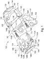
FIG. 1 is an exploded perspective view of a portion of a disc brake assembly having guide pins in accordance with a first embodiment of the present invention. -
FIG. 2 is perspective view of one of the guide pins ofFIG. 1 . -
FIG. 3 is a sectional view taken along line 3-3 ofFIG. 2 . -
FIG. 3A is an enlarged portion ofFIG. 3 . -
FIG. 3B is a partial sectional view of one of the guide pins ofFIG. 1 in a braking position. -
FIG. 4A is a partial sectional view of a guide pin in accordance with a second embodiment of the present invention. -
FIG. 4B is a partial sectional view of the guide pin ofFIG. 4A in a braking position. - Referring now to the drawings, there is illustrated in
FIG. 1 , a portion of a vehicle disc brake assembly, indicated generally at 100, with a knuckle, indicated generally at 102. The general structure and operation of thedisc brake assembly 100 is conventional in the art. For example, thedisc brake assembly 100 may be as disclosed inU.S. Patent Publication No. 2014/0231191 to Morais et al. . Thus, only those portions of the vehicledisc brake assembly 100 which are necessary for a full understanding of this invention will be explained and illustrated in detail. Also, although this invention will be described and illustrated in connection with the particular vehicle disc brake assembly disclosed herein, it will be appreciated that this invention may be used in connection with other vehicle disc brake assemblies, if so desired. - The
disc brake assembly 100 is a pin guided or pin sliding type of disc brake assembly and includes a generally C-shaped caliper, indicated generally at 104. Thecaliper 104 includes aninboard leg portion 106 and anoutboard leg portion 108 which are interconnected by anintermediate bridge portion 110. As will be discussed in detail, thecaliper 104 is secured to first and second guide pins 112A and 112B, respectively, which are slidably supported on an anchor bracket, indicated generally at 114. Theanchor bracket 114 is, in turn, secured to a stationary component of the vehicle by suitable fasteners, such as for example first andsecond bolts openings anchor bracket 114. Such a stationary component can be, for example, thesteering knuckle 102, when thedisc brake assembly 100 is installed for use on the front of the vehicle, or can be, for example, an axle flange or drum-in-hat adapter (not shown), when thedisc brake assembly 100 is installed for use on the rear of the vehicle. - In the illustrated embodiment, the
anchor bracket 114 includes first and second axially and outwardly extendingarms second arms outer tie bar 126. The first andsecond arms clips 128 are provided to slidably support an inboard brake shoe, indicated generally at 130, and an outboard brake shoe, indicated generally at 132, thereon. - In the illustrated embodiment, the
inboard brake shoe 130 includes abacking plate 134 and afriction pad 136. Theinboard backing plate 134 includes opposed ends having tabs orprotrusions 138 formed thereon, for supporting theinboard brake shoe 130 in theclips 128 installed in the channels of theanchor bracket 114. Alternatively, thetabs 138 may be omitted or a different bearing component known to those skilled in the art may be used. For example, pins may be used instead of thetabs 138. Theoutboard brake shoe 132 includes abacking plate 140 and afriction pad 142. Theoutboard backing plate 140 includes opposed ends having tabs orprotrusions 144 formed thereon, for supporting theoutboard brake shoe 132 in theclips 128 installed in the channels of theanchor bracket 114. Alternatively, theinboard brake shoe 130 can be supported on a brake piston/pistons (not shown) of thedisc brake assembly 100, and/or theoutboard brake shoe 132 can be supported on theoutboard leg portion 108 of thecaliper 104, if so desired. - An actuation means is provided for effecting the operation of the
disc brake assembly 100. For thedisc brake assembly 100, the actuation means includes a pair of brake pistons (not shown) each of which is disposed in a first or second counterbore orrecess inboard leg 106 of thecaliper 104. The actuation means may be of a suitable type known to those skilled in the art. For example, the actuation means may be hydraulic, electrical, pneumatic, or mechanical types. When thebrake assembly 100 is actuated, for example by a driver or a vehicle controller, a brake loading is developed on thebrake assembly 100. - As shown in
FIG. 1 , each of the first andsecond pins non-threaded bore second arms anchor bracket 114. Thefirst bore 148A has a longitudinal axis X1 and thesecond bore 148B has a longitudinal axis X2. Aboot seal 150 may be installed in each of the openings provided in thecaliper 104 through which each of the first andsecond pins fasteners second pins caliper 104. The first andsecond pins caliper 104 to theanchor bracket 114. The first andsecond fasteners second lugs caliper 104 and are installed in a corresponding internally threaded bore, provided inside eachpin - Referring now to
FIGS. 2-3B , there is illustrated in detail thefirst pin 112A slidably supported in thefirst bore 148A. As will be readily understood by one skilled in the art, although only thefirst pin 112A in thefirst bore 148A is described and illustrated here, thesecond pin 112B in thesecond bore 148B is similarly supported. - As shown in
FIG. 2 , thefirst pin 112A includes a head portion, indicated generally at 158, astem 160, and a longitudinal axis X3. Thestem 160 extends into thefirst bore 148A. Thehead portion 158 has anenlarged flange portion 162 and ahexagonal head 164. Along a length of thestem 160 are first andsecond grease grooves stem 160 are amain damper 168 and an isolation orsecondary damper 170. - As illustrated in
FIG. 3 , theisolation damper 170 is a single, continuous rubber strip having a single cross sectional profile. Alternatively, thestem 160 may have more than oneisolation damper 170. Alternatively, theisolation damper 170 may be comprised of individual members or pads making contact with thefirst bore 148A and/or have multiple cross sectional profiles and/or themain damper 168 may be comprised of individual members or pads making contact with thefirst bore 148A and/or have multiple cross sectional profiles. - As illustrated, the
main damper 168 andisolation damper 170 are parallel. Alternatively, themain damper 168 andisolation damper 170 may be other than parallel. - As illustrated, the
main damper 168 andisolation damper 170 are on opposite longitudinal sides of the stem 160 - i.e., at 12 o'clock and 6 o'clock positions, respectively. Alternatively, themain damper 168 andisolation damper 170 may be on other than opposite longitudinal sides of thestem 160. For example, themain damper 168 andisolation damper 170 may be at 12 o'clock and 5 or 7 o'clock, respectively. - The
main damper 168 is secured in a firstlongitudinal slot 172 and theisolation damper 170 is secured in a secondlongitudinal slot 174. Themain damper 168 is secured in thefirst slot 172 and theisolation damper 170 is secured in thesecond slot 174 using suitable means. For example, the main andisolation dampers second slots - The
isolation damper 170 is fabricated from a suitable material such as rubber and limits contact between thestem 160 and aninterior surface 176 of thefirst bore 148A. When there is no brake loading, theisolation damper 170 creates a clearance orair gap 178 between thestem 160 and theinterior surface 176 such that thestem 160 does not normally contact theinterior surface 176. - Under a low pressure brake loading, the
stem 160 seeks to displace or translate towards theinterior surface 176. Stiffness of theisolation damper 170 initially prevents contact between thestem 160 andinterior surface 176 while maintaining theclearance 178. As the brake loading increases and a compression threshold is reached, theisolation damper 170 will begin to compress. Theclearance 178 reduces in size under the low pressure brake loading from that illustrated inFIG. 3A , although thestem 160 does not contact theinterior surface 176. - Under an increased brake loading, the
isolation damper 170 compresses such that thestem 160 makes contact with theinterior surface 176 at a defined contact point, indicated generally at 180. A contact threshold at which theisolation damper 170 is sufficiently compressed that thestem 160 contacts theinterior surface 176 may be tuned or adjusted. The contact threshold may be tuned by varying the stiffness and/or composition of theisolation damper 170. For example, theisolation damper 170 may be fabricated from plastic. - The defined
contact point 180 may be defined by offsetting longitudinal axes of the first pin andfirst bore contact point 180 may be defined by theisolation damper 170 having a lower stiffness than themain damper 168. Alternatively, the definedcontact point 180 may be defined by having different relative stiffness between themain damper 168 andisolation dampers 170 allows the first pin andfirst bore - As illustrated, the defined
contact point 180 is defined at approximately a 6 o'clock position in the first bore 148. Alternatively, the definedcontact position 180 may be defined at other than the 6 o'clock position. For example, the defined contact position may be defined at 3 o'clock or 9 o'clock positions in thefirst bore 148A, or any position between 3 o'clock and 9 o'clock. - Referring now to
FIGS. 4A and 4B , there is illustrated a second embodiment of a guide pin 212A, produced in accordance with the present invention. Because the guide pin 212A is a variation of thefirst guide pin 112A ofFIGS. 1-3B , like reference numerals, increased by 100, designate corresponding parts in the drawings and detailed description thereof will be omitted. - The guide pin 212A has a
stem 260 having first andsecond isolation dampers second isolation dampers clearance 278 and limit contact between thestem 260 aninterior surface 176 of abore 248A. - When a contact threshold is exceeded, the
stem 260 contacts abore 248A at a defined contact point, indicated generally at 280. The definedcontact point 280 may be defined at least in part by varying stiffness between the first andsecond isolation dampers contact point 280 closer to thefirst isolation damper 270A, thesecond isolation damper 270B may be stiffer than thefirst isolation damper 270A.
Claims (15)
- A disc brake assembly (100) comprising:an anchor bracket (114) having at least one bore (148A, 148B, 248A) formed therein;a guide pin (112A, 112B, 212A) configured to be slidably supported in the bore (148A, 148B, 248A) and having a stem (160, 260);at least one main damper (168) configured to be disposed between the stem (160, 260) and an interior surface (176) of the bore (148A, 148B, 248A) and configured to bias a portion of the stem against the interior surface of the bore (148A, 148B, 248A) depending upon brake loading on the disc brake assembly, characterized by at least one secondary damper (170, 270A, 270B) configured to be disposed between the stem (160, 260) and the interior surface (176), wherein the secondary damper (170, 270A, 270B) is configured to limit a contact between the stem (160, 260) and the interior surface (176) depending upon the brake loading on the disc brake assembly (100).
- The disc brake assembly (100) of Claim 1 wherein the secondary damper (170, 270A, 270B) has a compression threshold and, when a brake loading exceeds the compression threshold, the secondary damper (170, 270A, 270B) is compressed.
- The disc brake assembly (100) of Claim 1 wherein the secondary damper (170, 270A, 270B) has a contact threshold and, when a brake loading exceeds the contact threshold, the secondary damper (170, 270A, 270B) allows contact between the stem (160, 260) and the interior surface (176).
- The disc brake assembly (100) of Claim 3 wherein contact between the stem (160, 260) and the interior surface (176) is at a defined contact point (180, 280).
- The disc brake assembly (100) of Claim 1 wherein the secondary damper (170, 270A, 270B) has a stiffness, and the stiffness is adjusted to set compression and contact thresholds.
- The disc brake assembly (100) of Claim 1 wherein the secondary damper (170) is opposite the main damper (168).
- The disc brake assembly (100) of Claim 1 wherein the secondary damper (170, 270A, 270B) limits contact between the stem (160, 260) and the interior surface (176) during brake loading on the disc brake assembly (100).
- The disc brake assembly (100) of Claim 1 wherein the secondary damper (170, 270A, 270B) limits contact between the stem (160, 260) and the interior surface (176) without brake loading on the disc brake assembly (100).
- The disc brake assembly (100) of Claim 1 wherein the secondary damper (170, 270A, 270B) holds the main damper (168) against the interior surface (176).
- The disc brake assembly (100) of Claim 1 wherein the stem (160, 260) contacts the bore (148A, 148B, 248A) at a defined contact point (180, 280).
- The disc brake assembly (100) of Claim 1 wherein the secondary damper has a lower stiffness than the main damper and the pin and the bore (148A, 148B, 248A) have a common longitudinal axis.
- The disc brake assembly (100) of Claim 1 further comprising:
a further secondary damper between the stem (260) and the interior surface (176), wherein the two secondary dampers (270A, 270B) together limit contact between the stem (260) and the interior surface (176). - The disc brake assembly (100) of Claim 1 further comprising:a brake caliper (104) secured to the guide pin (112A, 112B); andinboard and outboard brake shoes (130, 132) supported on the anchor bracket (114) by clips (128).
- The disc brake assembly according to one of Claims 1 to 13,
wherein a clearance (178, 278) exists between the stem (160, 260) and the interior surface (176) of the bore (148A, 148B, 248A) when there is no brake loading on the disc brake assembly (100) and as the brake loading increases the secondary damper (170, 270A, 270B) is compressed until the clearance (178, 278) is closed and a portion of the stem (160, 260) contacts the interior surface (176). - The disc brake assembly (100) of Claim 14 wherein the main damper and the secondary damper (170) are located on opposite longitudinal sides of the stem (160).
Applications Claiming Priority (2)
| Application Number | Priority Date | Filing Date | Title |
|---|---|---|---|
| US14/992,430 US9850967B2 (en) | 2016-01-11 | 2016-01-11 | Brake caliper guide pin low pressure isolation damper |
| PCT/US2017/012663 WO2017123484A1 (en) | 2016-01-11 | 2017-01-09 | Brake caliper guide pin low pressure isolation damper |
Publications (3)
| Publication Number | Publication Date |
|---|---|
| EP3402997A1 EP3402997A1 (en) | 2018-11-21 |
| EP3402997A4 EP3402997A4 (en) | 2019-08-21 |
| EP3402997B1 true EP3402997B1 (en) | 2021-03-10 |
Family
ID=59276232
Family Applications (1)
| Application Number | Title | Priority Date | Filing Date |
|---|---|---|---|
| EP17738766.9A Active EP3402997B1 (en) | 2016-01-11 | 2017-01-09 | Brake caliper guide pin low pressure isolation damper |
Country Status (6)
| Country | Link |
|---|---|
| US (2) | US9850967B2 (en) |
| EP (1) | EP3402997B1 (en) |
| JP (1) | JP6783322B2 (en) |
| KR (1) | KR102636937B1 (en) |
| CN (1) | CN108700144B (en) |
| WO (1) | WO2017123484A1 (en) |
Families Citing this family (9)
| Publication number | Priority date | Publication date | Assignee | Title |
|---|---|---|---|---|
| US9850967B2 (en) * | 2016-01-11 | 2017-12-26 | Kelsey-Hayes Company | Brake caliper guide pin low pressure isolation damper |
| US10054175B2 (en) * | 2016-11-18 | 2018-08-21 | Kelsey-Hayes Company | Controlled contact guide pin for vehicle disc brakes |
| US11698115B2 (en) * | 2019-02-12 | 2023-07-11 | ZF Active Safety US Inc. | Sliding mechanism for guide pins of a disc brake assembly |
| DE102019120362B4 (en) * | 2019-07-29 | 2026-01-15 | Kamax Holding Gmbh & Co. Kg | Fastener |
| US11773928B2 (en) * | 2020-12-14 | 2023-10-03 | Arvinmeritor Technology, Llc | Brake assembly having a guide pin assembly |
| DE102021125756A1 (en) | 2021-10-05 | 2023-04-06 | Zf Cv Systems Europe Bv | Disc brake with a pin guide for vehicles, in particular for commercial vehicles |
| EP4652382A1 (en) * | 2023-01-18 | 2025-11-26 | Hendrickson USA, L.L.C. | Shear-to-torque guide pin assembly for heavy-duty vehicles |
| US20250084904A1 (en) * | 2023-09-12 | 2025-03-13 | Bendix Commercial Vehicle Systems Llc | Air disc brake system drag reduction guide pin and methods for the use and assembly thereof |
| CN117515070A (en) * | 2023-11-22 | 2024-02-06 | 浙江西子富沃德电机有限公司 | caliper disc brake |
Family Cites Families (24)
| Publication number | Priority date | Publication date | Assignee | Title |
|---|---|---|---|---|
| US4084665A (en) * | 1976-10-22 | 1978-04-18 | The Bendix Corporation | Disc brake and mounting means therefor |
| JPS5517769A (en) * | 1978-07-25 | 1980-02-07 | Akebono Brake Ind Co Ltd | Calliper guide mechanism for pin type disc brake |
| IN150357B (en) * | 1979-01-18 | 1982-09-18 | Lucas Industries Ltd | |
| US4310075A (en) * | 1980-03-10 | 1982-01-12 | The Bendix Corporation | Disc brake |
| US4446948A (en) | 1982-03-29 | 1984-05-08 | General Motors Corporation | Disc brake caliper mount |
| JPH027304Y2 (en) * | 1985-08-28 | 1990-02-21 | ||
| JP2560988Y2 (en) * | 1990-11-09 | 1998-01-26 | 日信工業株式会社 | Pin slide type vehicle disc brake |
| JP3089928B2 (en) | 1993-12-29 | 2000-09-18 | トヨタ自動車株式会社 | Hydraulic brake device |
| JPH07197962A (en) | 1993-12-28 | 1995-08-01 | Akebono Brake Ind Co Ltd | Sliding guide mechanism for caliper of disc brake |
| JPH1061686A (en) * | 1996-08-14 | 1998-03-06 | Akebono Brake Ind Co Ltd | Disc brake device |
| JPH11257385A (en) | 1998-03-10 | 1999-09-21 | Nissan Motor Co Ltd | Disc brake |
| US6026938A (en) * | 1998-08-27 | 2000-02-22 | Robert Bosch Technology Corp | Guide pin and bearing for a disc brake |
| US6397983B1 (en) | 2001-02-23 | 2002-06-04 | Akebono Corporation North America | Automatic adjustment for disc brake pad |
| JP4623874B2 (en) * | 2001-07-06 | 2011-02-02 | 日立オートモティブシステムズ株式会社 | Disc brake |
| DE102007053902A1 (en) * | 2007-11-09 | 2009-05-20 | Knorr-Bremse Systeme für Nutzfahrzeuge GmbH | Disc brake for a commercial vehicle |
| JP2012072842A (en) | 2010-09-29 | 2012-04-12 | Akebono Brake Ind Co Ltd | Floating type disc brake |
| JP2012107740A (en) | 2010-10-28 | 2012-06-07 | Advics Co Ltd | Pin slide type floating disc brake |
| JP5621676B2 (en) * | 2011-03-22 | 2014-11-12 | トヨタ自動車株式会社 | Disc brake device and caliper slide mechanism |
| CN202381593U (en) * | 2011-11-21 | 2012-08-15 | 青岛华瑞汽车零部件有限公司 | Double-cylinder hydraulic floatable caliper disc brake |
| EP2914866B1 (en) | 2012-11-01 | 2018-12-05 | Kelsey-Hayes Company | Guide pin for disc brake assembly, disc brake assembly including such a guide pin and method for producing a disc brake assembly including such a guide pin |
| US9587686B2 (en) | 2012-11-01 | 2017-03-07 | Kelsey-Hayes Company | Guide pin for disc brake assembly and disc brake assembly including such a guide pin |
| US9353810B2 (en) | 2013-02-21 | 2016-05-31 | Kelsey-Hayes Company | Disc brake assembly with non-rotatable vehicle component and method for producing same |
| DE102013011469A1 (en) | 2013-07-10 | 2015-01-15 | Lucas Automotive Gmbh | Guide device for a floating caliper disc brake |
| US9850967B2 (en) * | 2016-01-11 | 2017-12-26 | Kelsey-Hayes Company | Brake caliper guide pin low pressure isolation damper |
-
2016
- 2016-01-11 US US14/992,430 patent/US9850967B2/en not_active Expired - Fee Related
-
2017
- 2017-01-09 WO PCT/US2017/012663 patent/WO2017123484A1/en not_active Ceased
- 2017-01-09 JP JP2018554646A patent/JP6783322B2/en not_active Expired - Fee Related
- 2017-01-09 EP EP17738766.9A patent/EP3402997B1/en active Active
- 2017-01-09 CN CN201780006298.9A patent/CN108700144B/en not_active Expired - Fee Related
- 2017-01-09 KR KR1020187022890A patent/KR102636937B1/en active Active
- 2017-12-22 US US15/851,807 patent/US10094438B2/en active Active
Non-Patent Citations (1)
| Title |
|---|
| None * |
Also Published As
| Publication number | Publication date |
|---|---|
| US20180119760A1 (en) | 2018-05-03 |
| JP6783322B2 (en) | 2020-11-11 |
| EP3402997A4 (en) | 2019-08-21 |
| CN108700144B (en) | 2020-08-25 |
| EP3402997A1 (en) | 2018-11-21 |
| JP2019501353A (en) | 2019-01-17 |
| KR102636937B1 (en) | 2024-02-15 |
| CN108700144A (en) | 2018-10-23 |
| US20170198771A1 (en) | 2017-07-13 |
| US9850967B2 (en) | 2017-12-26 |
| KR20180094123A (en) | 2018-08-22 |
| WO2017123484A1 (en) | 2017-07-20 |
| US10094438B2 (en) | 2018-10-09 |
Similar Documents
| Publication | Publication Date | Title |
|---|---|---|
| US10094438B2 (en) | Brake caliper guide pin low pressure isolation damper | |
| US6223866B1 (en) | Damped pad spring for use in a disc brake assembly | |
| EP2619474B1 (en) | Anchor bracket for use in a disc brake assembly and method for making the same | |
| US5927446A (en) | Slide pin bushing and boot seal assembly for disc brake assembly | |
| US6386335B1 (en) | Anchor bracket and brake shoe assembly for use in a disc brake assembly | |
| US10054175B2 (en) | Controlled contact guide pin for vehicle disc brakes | |
| US5921354A (en) | Self-energizing anti-creep parking and emergency brake mechanism for disc brake assembly | |
| US6039156A (en) | Slide pin bushing for disc brake assembly | |
| US9353810B2 (en) | Disc brake assembly with non-rotatable vehicle component and method for producing same | |
| US10041553B2 (en) | Clip for use in a disc brake assembly and disc brake assembly including such a clip | |
| US10458494B2 (en) | Bushing for brake caliper guide rod fasteners | |
| US11698115B2 (en) | Sliding mechanism for guide pins of a disc brake assembly | |
| US20040188191A1 (en) | Slide pin bushing for disc brake assembly | |
| US9284999B2 (en) | Guide pin for disc brake assembly, disc brake assembly including such a guide pin and method for producing a disc brake assembly including such a guide pin | |
| US20060289253A1 (en) | Monoblock caliper housing for a disc brake assembly | |
| US6257378B1 (en) | Caliper for disc brake assembly | |
| US20090145702A1 (en) | Brake pad for a vehicle disc brake assembly | |
| US6374965B1 (en) | Damped brake shoe support device for drum brake assembly | |
| US6598716B1 (en) | Rotor for a vehicle brake assembly and method for producing same | |
| US20060289251A1 (en) | Taper wear compensation of a friction pad for a disc brake assembly |
Legal Events
| Date | Code | Title | Description |
|---|---|---|---|
| STAA | Information on the status of an ep patent application or granted ep patent |
Free format text: STATUS: THE INTERNATIONAL PUBLICATION HAS BEEN MADE |
|
| PUAI | Public reference made under article 153(3) epc to a published international application that has entered the european phase |
Free format text: ORIGINAL CODE: 0009012 |
|
| STAA | Information on the status of an ep patent application or granted ep patent |
Free format text: STATUS: REQUEST FOR EXAMINATION WAS MADE |
|
| 17P | Request for examination filed |
Effective date: 20180808 |
|
| AK | Designated contracting states |
Kind code of ref document: A1 Designated state(s): AL AT BE BG CH CY CZ DE DK EE ES FI FR GB GR HR HU IE IS IT LI LT LU LV MC MK MT NL NO PL PT RO RS SE SI SK SM TR |
|
| AX | Request for extension of the european patent |
Extension state: BA ME |
|
| DAV | Request for validation of the european patent (deleted) | ||
| DAX | Request for extension of the european patent (deleted) | ||
| A4 | Supplementary search report drawn up and despatched |
Effective date: 20190722 |
|
| RIC1 | Information provided on ipc code assigned before grant |
Ipc: F16D 55/227 20060101ALI20190716BHEP Ipc: F16D 65/00 20060101ALI20190716BHEP Ipc: F16D 55/2265 20060101AFI20190716BHEP |
|
| RAP1 | Party data changed (applicant data changed or rights of an application transferred) |
Owner name: ZF ACTIVE SAFETY US INC. |
|
| GRAP | Despatch of communication of intention to grant a patent |
Free format text: ORIGINAL CODE: EPIDOSNIGR1 |
|
| STAA | Information on the status of an ep patent application or granted ep patent |
Free format text: STATUS: GRANT OF PATENT IS INTENDED |
|
| RIC1 | Information provided on ipc code assigned before grant |
Ipc: F16D 55/227 20060101ALI20200703BHEP Ipc: F16D 55/2265 20060101AFI20200703BHEP Ipc: F16D 65/00 20060101ALI20200703BHEP |
|
| INTG | Intention to grant announced |
Effective date: 20200722 |
|
| GRAS | Grant fee paid |
Free format text: ORIGINAL CODE: EPIDOSNIGR3 |
|
| GRAA | (expected) grant |
Free format text: ORIGINAL CODE: 0009210 |
|
| STAA | Information on the status of an ep patent application or granted ep patent |
Free format text: STATUS: THE PATENT HAS BEEN GRANTED |
|
| AK | Designated contracting states |
Kind code of ref document: B1 Designated state(s): AL AT BE BG CH CY CZ DE DK EE ES FI FR GB GR HR HU IE IS IT LI LT LU LV MC MK MT NL NO PL PT RO RS SE SI SK SM TR |
|
| REG | Reference to a national code |
Ref country code: GB Ref legal event code: FG4D |
|
| REG | Reference to a national code |
Ref country code: AT Ref legal event code: REF Ref document number: 1370129 Country of ref document: AT Kind code of ref document: T Effective date: 20210315 Ref country code: CH Ref legal event code: EP |
|
| REG | Reference to a national code |
Ref country code: IE Ref legal event code: FG4D |
|
| REG | Reference to a national code |
Ref country code: DE Ref legal event code: R096 Ref document number: 602017034322 Country of ref document: DE |
|
| REG | Reference to a national code |
Ref country code: LT Ref legal event code: MG9D |
|
| PG25 | Lapsed in a contracting state [announced via postgrant information from national office to epo] |
Ref country code: LT Free format text: LAPSE BECAUSE OF FAILURE TO SUBMIT A TRANSLATION OF THE DESCRIPTION OR TO PAY THE FEE WITHIN THE PRESCRIBED TIME-LIMIT Effective date: 20210310 Ref country code: BG Free format text: LAPSE BECAUSE OF FAILURE TO SUBMIT A TRANSLATION OF THE DESCRIPTION OR TO PAY THE FEE WITHIN THE PRESCRIBED TIME-LIMIT Effective date: 20210610 Ref country code: HR Free format text: LAPSE BECAUSE OF FAILURE TO SUBMIT A TRANSLATION OF THE DESCRIPTION OR TO PAY THE FEE WITHIN THE PRESCRIBED TIME-LIMIT Effective date: 20210310 Ref country code: FI Free format text: LAPSE BECAUSE OF FAILURE TO SUBMIT A TRANSLATION OF THE DESCRIPTION OR TO PAY THE FEE WITHIN THE PRESCRIBED TIME-LIMIT Effective date: 20210310 Ref country code: GR Free format text: LAPSE BECAUSE OF FAILURE TO SUBMIT A TRANSLATION OF THE DESCRIPTION OR TO PAY THE FEE WITHIN THE PRESCRIBED TIME-LIMIT Effective date: 20210611 Ref country code: NO Free format text: LAPSE BECAUSE OF FAILURE TO SUBMIT A TRANSLATION OF THE DESCRIPTION OR TO PAY THE FEE WITHIN THE PRESCRIBED TIME-LIMIT Effective date: 20210610 |
|
| REG | Reference to a national code |
Ref country code: AT Ref legal event code: MK05 Ref document number: 1370129 Country of ref document: AT Kind code of ref document: T Effective date: 20210310 |
|
| REG | Reference to a national code |
Ref country code: NL Ref legal event code: MP Effective date: 20210310 |
|
| PG25 | Lapsed in a contracting state [announced via postgrant information from national office to epo] |
Ref country code: SE Free format text: LAPSE BECAUSE OF FAILURE TO SUBMIT A TRANSLATION OF THE DESCRIPTION OR TO PAY THE FEE WITHIN THE PRESCRIBED TIME-LIMIT Effective date: 20210310 Ref country code: RS Free format text: LAPSE BECAUSE OF FAILURE TO SUBMIT A TRANSLATION OF THE DESCRIPTION OR TO PAY THE FEE WITHIN THE PRESCRIBED TIME-LIMIT Effective date: 20210310 Ref country code: LV Free format text: LAPSE BECAUSE OF FAILURE TO SUBMIT A TRANSLATION OF THE DESCRIPTION OR TO PAY THE FEE WITHIN THE PRESCRIBED TIME-LIMIT Effective date: 20210310 |
|
| PG25 | Lapsed in a contracting state [announced via postgrant information from national office to epo] |
Ref country code: NL Free format text: LAPSE BECAUSE OF FAILURE TO SUBMIT A TRANSLATION OF THE DESCRIPTION OR TO PAY THE FEE WITHIN THE PRESCRIBED TIME-LIMIT Effective date: 20210310 |
|
| PG25 | Lapsed in a contracting state [announced via postgrant information from national office to epo] |
Ref country code: SM Free format text: LAPSE BECAUSE OF FAILURE TO SUBMIT A TRANSLATION OF THE DESCRIPTION OR TO PAY THE FEE WITHIN THE PRESCRIBED TIME-LIMIT Effective date: 20210310 Ref country code: AT Free format text: LAPSE BECAUSE OF FAILURE TO SUBMIT A TRANSLATION OF THE DESCRIPTION OR TO PAY THE FEE WITHIN THE PRESCRIBED TIME-LIMIT Effective date: 20210310 Ref country code: CZ Free format text: LAPSE BECAUSE OF FAILURE TO SUBMIT A TRANSLATION OF THE DESCRIPTION OR TO PAY THE FEE WITHIN THE PRESCRIBED TIME-LIMIT Effective date: 20210310 Ref country code: EE Free format text: LAPSE BECAUSE OF FAILURE TO SUBMIT A TRANSLATION OF THE DESCRIPTION OR TO PAY THE FEE WITHIN THE PRESCRIBED TIME-LIMIT Effective date: 20210310 |
|
| PG25 | Lapsed in a contracting state [announced via postgrant information from national office to epo] |
Ref country code: PL Free format text: LAPSE BECAUSE OF FAILURE TO SUBMIT A TRANSLATION OF THE DESCRIPTION OR TO PAY THE FEE WITHIN THE PRESCRIBED TIME-LIMIT Effective date: 20210310 Ref country code: PT Free format text: LAPSE BECAUSE OF FAILURE TO SUBMIT A TRANSLATION OF THE DESCRIPTION OR TO PAY THE FEE WITHIN THE PRESCRIBED TIME-LIMIT Effective date: 20210712 Ref country code: RO Free format text: LAPSE BECAUSE OF FAILURE TO SUBMIT A TRANSLATION OF THE DESCRIPTION OR TO PAY THE FEE WITHIN THE PRESCRIBED TIME-LIMIT Effective date: 20210310 Ref country code: SK Free format text: LAPSE BECAUSE OF FAILURE TO SUBMIT A TRANSLATION OF THE DESCRIPTION OR TO PAY THE FEE WITHIN THE PRESCRIBED TIME-LIMIT Effective date: 20210310 Ref country code: IS Free format text: LAPSE BECAUSE OF FAILURE TO SUBMIT A TRANSLATION OF THE DESCRIPTION OR TO PAY THE FEE WITHIN THE PRESCRIBED TIME-LIMIT Effective date: 20210710 |
|
| REG | Reference to a national code |
Ref country code: DE Ref legal event code: R097 Ref document number: 602017034322 Country of ref document: DE |
|
| PLBE | No opposition filed within time limit |
Free format text: ORIGINAL CODE: 0009261 |
|
| STAA | Information on the status of an ep patent application or granted ep patent |
Free format text: STATUS: NO OPPOSITION FILED WITHIN TIME LIMIT |
|
| PG25 | Lapsed in a contracting state [announced via postgrant information from national office to epo] |
Ref country code: AL Free format text: LAPSE BECAUSE OF FAILURE TO SUBMIT A TRANSLATION OF THE DESCRIPTION OR TO PAY THE FEE WITHIN THE PRESCRIBED TIME-LIMIT Effective date: 20210310 Ref country code: DK Free format text: LAPSE BECAUSE OF FAILURE TO SUBMIT A TRANSLATION OF THE DESCRIPTION OR TO PAY THE FEE WITHIN THE PRESCRIBED TIME-LIMIT Effective date: 20210310 Ref country code: ES Free format text: LAPSE BECAUSE OF FAILURE TO SUBMIT A TRANSLATION OF THE DESCRIPTION OR TO PAY THE FEE WITHIN THE PRESCRIBED TIME-LIMIT Effective date: 20210310 |
|
| 26N | No opposition filed |
Effective date: 20211213 |
|
| PG25 | Lapsed in a contracting state [announced via postgrant information from national office to epo] |
Ref country code: SI Free format text: LAPSE BECAUSE OF FAILURE TO SUBMIT A TRANSLATION OF THE DESCRIPTION OR TO PAY THE FEE WITHIN THE PRESCRIBED TIME-LIMIT Effective date: 20210310 |
|
| PG25 | Lapsed in a contracting state [announced via postgrant information from national office to epo] |
Ref country code: IT Free format text: LAPSE BECAUSE OF FAILURE TO SUBMIT A TRANSLATION OF THE DESCRIPTION OR TO PAY THE FEE WITHIN THE PRESCRIBED TIME-LIMIT Effective date: 20210310 |
|
| PG25 | Lapsed in a contracting state [announced via postgrant information from national office to epo] |
Ref country code: IS Free format text: LAPSE BECAUSE OF FAILURE TO SUBMIT A TRANSLATION OF THE DESCRIPTION OR TO PAY THE FEE WITHIN THE PRESCRIBED TIME-LIMIT Effective date: 20210710 |
|
| PG25 | Lapsed in a contracting state [announced via postgrant information from national office to epo] |
Ref country code: MC Free format text: LAPSE BECAUSE OF FAILURE TO SUBMIT A TRANSLATION OF THE DESCRIPTION OR TO PAY THE FEE WITHIN THE PRESCRIBED TIME-LIMIT Effective date: 20210310 |
|
| REG | Reference to a national code |
Ref country code: CH Ref legal event code: PL |
|
| REG | Reference to a national code |
Ref country code: BE Ref legal event code: MM Effective date: 20220131 |
|
| PG25 | Lapsed in a contracting state [announced via postgrant information from national office to epo] |
Ref country code: LU Free format text: LAPSE BECAUSE OF NON-PAYMENT OF DUE FEES Effective date: 20220109 |
|
| PG25 | Lapsed in a contracting state [announced via postgrant information from national office to epo] |
Ref country code: BE Free format text: LAPSE BECAUSE OF NON-PAYMENT OF DUE FEES Effective date: 20220131 |
|
| PG25 | Lapsed in a contracting state [announced via postgrant information from national office to epo] |
Ref country code: LI Free format text: LAPSE BECAUSE OF NON-PAYMENT OF DUE FEES Effective date: 20220131 Ref country code: CH Free format text: LAPSE BECAUSE OF NON-PAYMENT OF DUE FEES Effective date: 20220131 |
|
| PG25 | Lapsed in a contracting state [announced via postgrant information from national office to epo] |
Ref country code: IE Free format text: LAPSE BECAUSE OF NON-PAYMENT OF DUE FEES Effective date: 20220109 |
|
| PGFP | Annual fee paid to national office [announced via postgrant information from national office to epo] |
Ref country code: GB Payment date: 20221117 Year of fee payment: 7 Ref country code: FR Payment date: 20221122 Year of fee payment: 7 |
|
| P01 | Opt-out of the competence of the unified patent court (upc) registered |
Effective date: 20230530 |
|
| PG25 | Lapsed in a contracting state [announced via postgrant information from national office to epo] |
Ref country code: HU Free format text: LAPSE BECAUSE OF FAILURE TO SUBMIT A TRANSLATION OF THE DESCRIPTION OR TO PAY THE FEE WITHIN THE PRESCRIBED TIME-LIMIT; INVALID AB INITIO Effective date: 20170109 |
|
| PG25 | Lapsed in a contracting state [announced via postgrant information from national office to epo] |
Ref country code: MK Free format text: LAPSE BECAUSE OF FAILURE TO SUBMIT A TRANSLATION OF THE DESCRIPTION OR TO PAY THE FEE WITHIN THE PRESCRIBED TIME-LIMIT Effective date: 20210310 Ref country code: CY Free format text: LAPSE BECAUSE OF FAILURE TO SUBMIT A TRANSLATION OF THE DESCRIPTION OR TO PAY THE FEE WITHIN THE PRESCRIBED TIME-LIMIT Effective date: 20210310 |
|
| PG25 | Lapsed in a contracting state [announced via postgrant information from national office to epo] |
Ref country code: TR Free format text: LAPSE BECAUSE OF FAILURE TO SUBMIT A TRANSLATION OF THE DESCRIPTION OR TO PAY THE FEE WITHIN THE PRESCRIBED TIME-LIMIT Effective date: 20210310 |
|
| GBPC | Gb: european patent ceased through non-payment of renewal fee |
Effective date: 20240109 |
|
| PG25 | Lapsed in a contracting state [announced via postgrant information from national office to epo] |
Ref country code: MT Free format text: LAPSE BECAUSE OF FAILURE TO SUBMIT A TRANSLATION OF THE DESCRIPTION OR TO PAY THE FEE WITHIN THE PRESCRIBED TIME-LIMIT Effective date: 20210310 |
|
| PG25 | Lapsed in a contracting state [announced via postgrant information from national office to epo] |
Ref country code: GB Free format text: LAPSE BECAUSE OF NON-PAYMENT OF DUE FEES Effective date: 20240109 |
|
| PG25 | Lapsed in a contracting state [announced via postgrant information from national office to epo] |
Ref country code: FR Free format text: LAPSE BECAUSE OF NON-PAYMENT OF DUE FEES Effective date: 20240131 |
|
| PG25 | Lapsed in a contracting state [announced via postgrant information from national office to epo] |
Ref country code: GB Free format text: LAPSE BECAUSE OF NON-PAYMENT OF DUE FEES Effective date: 20240109 Ref country code: FR Free format text: LAPSE BECAUSE OF NON-PAYMENT OF DUE FEES Effective date: 20240131 |
|
| PGFP | Annual fee paid to national office [announced via postgrant information from national office to epo] |
Ref country code: DE Payment date: 20241203 Year of fee payment: 9 |