EP3402656B1 - All-composite torque tube with metal eyelets - Google Patents
All-composite torque tube with metal eyelets Download PDFInfo
- Publication number
- EP3402656B1 EP3402656B1 EP16885428.9A EP16885428A EP3402656B1 EP 3402656 B1 EP3402656 B1 EP 3402656B1 EP 16885428 A EP16885428 A EP 16885428A EP 3402656 B1 EP3402656 B1 EP 3402656B1
- Authority
- EP
- European Patent Office
- Prior art keywords
- fiber tow
- winding
- mandrel
- flange
- end sleeve
- Prior art date
- Legal status (The legal status is an assumption and is not a legal conclusion. Google has not performed a legal analysis and makes no representation as to the accuracy of the status listed.)
- Active
Links
Images


Classifications
-
- B—PERFORMING OPERATIONS; TRANSPORTING
- B29—WORKING OF PLASTICS; WORKING OF SUBSTANCES IN A PLASTIC STATE IN GENERAL
- B29C—SHAPING OR JOINING OF PLASTICS; SHAPING OF MATERIAL IN A PLASTIC STATE, NOT OTHERWISE PROVIDED FOR; AFTER-TREATMENT OF THE SHAPED PRODUCTS, e.g. REPAIRING
- B29C70/00—Shaping composites, i.e. plastics material comprising reinforcements, fillers or preformed parts, e.g. inserts
- B29C70/04—Shaping composites, i.e. plastics material comprising reinforcements, fillers or preformed parts, e.g. inserts comprising reinforcements only, e.g. self-reinforcing plastics
- B29C70/28—Shaping operations therefor
- B29C70/30—Shaping by lay-up, i.e. applying fibres, tape or broadsheet on a mould, former or core; Shaping by spray-up, i.e. spraying of fibres on a mould, former or core
- B29C70/32—Shaping by lay-up, i.e. applying fibres, tape or broadsheet on a mould, former or core; Shaping by spray-up, i.e. spraying of fibres on a mould, former or core on a rotating mould, former or core
-
- B—PERFORMING OPERATIONS; TRANSPORTING
- B29—WORKING OF PLASTICS; WORKING OF SUBSTANCES IN A PLASTIC STATE IN GENERAL
- B29C—SHAPING OR JOINING OF PLASTICS; SHAPING OF MATERIAL IN A PLASTIC STATE, NOT OTHERWISE PROVIDED FOR; AFTER-TREATMENT OF THE SHAPED PRODUCTS, e.g. REPAIRING
- B29C35/00—Heating, cooling or curing, e.g. crosslinking or vulcanising; Apparatus therefor
- B29C35/02—Heating or curing, e.g. crosslinking or vulcanizing during moulding, e.g. in a mould
-
- B—PERFORMING OPERATIONS; TRANSPORTING
- B29—WORKING OF PLASTICS; WORKING OF SUBSTANCES IN A PLASTIC STATE IN GENERAL
- B29C—SHAPING OR JOINING OF PLASTICS; SHAPING OF MATERIAL IN A PLASTIC STATE, NOT OTHERWISE PROVIDED FOR; AFTER-TREATMENT OF THE SHAPED PRODUCTS, e.g. REPAIRING
- B29C70/00—Shaping composites, i.e. plastics material comprising reinforcements, fillers or preformed parts, e.g. inserts
- B29C70/04—Shaping composites, i.e. plastics material comprising reinforcements, fillers or preformed parts, e.g. inserts comprising reinforcements only, e.g. self-reinforcing plastics
- B29C70/06—Fibrous reinforcements only
- B29C70/10—Fibrous reinforcements only characterised by the structure of fibrous reinforcements, e.g. hollow fibres
- B29C70/16—Fibrous reinforcements only characterised by the structure of fibrous reinforcements, e.g. hollow fibres using fibres of substantial or continuous length
- B29C70/22—Fibrous reinforcements only characterised by the structure of fibrous reinforcements, e.g. hollow fibres using fibres of substantial or continuous length oriented in at least two directions forming a two-dimensional [2D] structure
- B29C70/222—Fibrous reinforcements only characterised by the structure of fibrous reinforcements, e.g. hollow fibres using fibres of substantial or continuous length oriented in at least two directions forming a two-dimensional [2D] structure the structure being shaped to form a three dimensional configuration
-
- B—PERFORMING OPERATIONS; TRANSPORTING
- B29—WORKING OF PLASTICS; WORKING OF SUBSTANCES IN A PLASTIC STATE IN GENERAL
- B29C—SHAPING OR JOINING OF PLASTICS; SHAPING OF MATERIAL IN A PLASTIC STATE, NOT OTHERWISE PROVIDED FOR; AFTER-TREATMENT OF THE SHAPED PRODUCTS, e.g. REPAIRING
- B29C70/00—Shaping composites, i.e. plastics material comprising reinforcements, fillers or preformed parts, e.g. inserts
- B29C70/04—Shaping composites, i.e. plastics material comprising reinforcements, fillers or preformed parts, e.g. inserts comprising reinforcements only, e.g. self-reinforcing plastics
- B29C70/28—Shaping operations therefor
- B29C70/30—Shaping by lay-up, i.e. applying fibres, tape or broadsheet on a mould, former or core; Shaping by spray-up, i.e. spraying of fibres on a mould, former or core
- B29C70/302—Details of the edges of fibre composites, e.g. edge finishing or means to avoid delamination
-
- B—PERFORMING OPERATIONS; TRANSPORTING
- B29—WORKING OF PLASTICS; WORKING OF SUBSTANCES IN A PLASTIC STATE IN GENERAL
- B29C—SHAPING OR JOINING OF PLASTICS; SHAPING OF MATERIAL IN A PLASTIC STATE, NOT OTHERWISE PROVIDED FOR; AFTER-TREATMENT OF THE SHAPED PRODUCTS, e.g. REPAIRING
- B29C70/00—Shaping composites, i.e. plastics material comprising reinforcements, fillers or preformed parts, e.g. inserts
- B29C70/68—Shaping composites, i.e. plastics material comprising reinforcements, fillers or preformed parts, e.g. inserts by incorporating or moulding on preformed parts, e.g. inserts or layers, e.g. foam blocks
- B29C70/86—Incorporated in coherent impregnated reinforcing layers, e.g. by winding
-
- B—PERFORMING OPERATIONS; TRANSPORTING
- B64—AIRCRAFT; AVIATION; COSMONAUTICS
- B64C—AEROPLANES; HELICOPTERS
- B64C13/00—Control systems or transmitting systems for actuating flying-control surfaces, lift-increasing flaps, air brakes, or spoilers
- B64C13/24—Transmitting means
- B64C13/26—Transmitting means without power amplification or where power amplification is irrelevant
- B64C13/28—Transmitting means without power amplification or where power amplification is irrelevant mechanical
- B64C13/30—Transmitting means without power amplification or where power amplification is irrelevant mechanical using cable, chain, or rod mechanisms
-
- B—PERFORMING OPERATIONS; TRANSPORTING
- B64—AIRCRAFT; AVIATION; COSMONAUTICS
- B64D—EQUIPMENT FOR FITTING IN OR TO AIRCRAFT; FLIGHT SUITS; PARACHUTES; ARRANGEMENT OR MOUNTING OF POWER PLANTS OR PROPULSION TRANSMISSIONS IN AIRCRAFT
- B64D35/00—Transmitting power from power plants to propellers or rotors; Arrangements of transmissions
-
- F—MECHANICAL ENGINEERING; LIGHTING; HEATING; WEAPONS; BLASTING
- F16—ENGINEERING ELEMENTS AND UNITS; GENERAL MEASURES FOR PRODUCING AND MAINTAINING EFFECTIVE FUNCTIONING OF MACHINES OR INSTALLATIONS; THERMAL INSULATION IN GENERAL
- F16C—SHAFTS; FLEXIBLE SHAFTS; ELEMENTS OR CRANKSHAFT MECHANISMS; ROTARY BODIES OTHER THAN GEARING ELEMENTS; BEARINGS
- F16C3/00—Shafts; Axles; Cranks; Eccentrics
- F16C3/02—Shafts; Axles
- F16C3/026—Shafts made of fibre reinforced resin
-
- B—PERFORMING OPERATIONS; TRANSPORTING
- B29—WORKING OF PLASTICS; WORKING OF SUBSTANCES IN A PLASTIC STATE IN GENERAL
- B29K—INDEXING SCHEME ASSOCIATED WITH SUBCLASSES B29B, B29C OR B29D, RELATING TO MOULDING MATERIALS OR TO MATERIALS FOR MOULDS, REINFORCEMENTS, FILLERS OR PREFORMED PARTS, e.g. INSERTS
- B29K2101/00—Use of unspecified macromolecular compounds as moulding material
- B29K2101/10—Thermosetting resins
-
- B—PERFORMING OPERATIONS; TRANSPORTING
- B29—WORKING OF PLASTICS; WORKING OF SUBSTANCES IN A PLASTIC STATE IN GENERAL
- B29K—INDEXING SCHEME ASSOCIATED WITH SUBCLASSES B29B, B29C OR B29D, RELATING TO MOULDING MATERIALS OR TO MATERIALS FOR MOULDS, REINFORCEMENTS, FILLERS OR PREFORMED PARTS, e.g. INSERTS
- B29K2105/00—Condition, form or state of moulded material or of the material to be shaped
- B29K2105/06—Condition, form or state of moulded material or of the material to be shaped containing reinforcements, fillers or inserts
- B29K2105/08—Condition, form or state of moulded material or of the material to be shaped containing reinforcements, fillers or inserts of continuous length, e.g. cords, rovings, mats, fabrics, strands or yarns
- B29K2105/0872—Prepregs
-
- B—PERFORMING OPERATIONS; TRANSPORTING
- B29—WORKING OF PLASTICS; WORKING OF SUBSTANCES IN A PLASTIC STATE IN GENERAL
- B29K—INDEXING SCHEME ASSOCIATED WITH SUBCLASSES B29B, B29C OR B29D, RELATING TO MOULDING MATERIALS OR TO MATERIALS FOR MOULDS, REINFORCEMENTS, FILLERS OR PREFORMED PARTS, e.g. INSERTS
- B29K2995/00—Properties of moulding materials, reinforcements, fillers, preformed parts or moulds
- B29K2995/0037—Other properties
- B29K2995/0082—Flexural strength; Flexion stiffness
-
- B—PERFORMING OPERATIONS; TRANSPORTING
- B29—WORKING OF PLASTICS; WORKING OF SUBSTANCES IN A PLASTIC STATE IN GENERAL
- B29L—INDEXING SCHEME ASSOCIATED WITH SUBCLASS B29C, RELATING TO PARTICULAR ARTICLES
- B29L2023/00—Tubular articles
- B29L2023/005—Hoses, i.e. flexible
-
- B—PERFORMING OPERATIONS; TRANSPORTING
- B29—WORKING OF PLASTICS; WORKING OF SUBSTANCES IN A PLASTIC STATE IN GENERAL
- B29L—INDEXING SCHEME ASSOCIATED WITH SUBCLASS B29C, RELATING TO PARTICULAR ARTICLES
- B29L2031/00—Other particular articles
- B29L2031/30—Vehicles, e.g. ships or aircraft, or body parts thereof
- B29L2031/3076—Aircrafts
-
- B—PERFORMING OPERATIONS; TRANSPORTING
- B29—WORKING OF PLASTICS; WORKING OF SUBSTANCES IN A PLASTIC STATE IN GENERAL
- B29L—INDEXING SCHEME ASSOCIATED WITH SUBCLASS B29C, RELATING TO PARTICULAR ARTICLES
- B29L2031/00—Other particular articles
- B29L2031/748—Machines or parts thereof not otherwise provided for
- B29L2031/75—Shafts
-
- Y—GENERAL TAGGING OF NEW TECHNOLOGICAL DEVELOPMENTS; GENERAL TAGGING OF CROSS-SECTIONAL TECHNOLOGIES SPANNING OVER SEVERAL SECTIONS OF THE IPC; TECHNICAL SUBJECTS COVERED BY FORMER USPC CROSS-REFERENCE ART COLLECTIONS [XRACs] AND DIGESTS
- Y02—TECHNOLOGIES OR APPLICATIONS FOR MITIGATION OR ADAPTATION AGAINST CLIMATE CHANGE
- Y02T—CLIMATE CHANGE MITIGATION TECHNOLOGIES RELATED TO TRANSPORTATION
- Y02T50/00—Aeronautics or air transport
- Y02T50/40—Weight reduction
Definitions
- the present invention relates generally to torque tubes (sometimes referred to as torque shafts) used on an aircraft utility or flight control drive line, or on any drive line that requires a torque tube for transmitting torque.
- torque tubes sometimes referred to as torque shafts
- a torque tube transmits static and dynamic torsional loads in power transmission applications.
- torque tubes are commonly used in aircraft to provide power transmission for actuating and braking flight control surfaces, e.g. flaps and slats, and for actuating aircraft doors and door latches.
- Each end of a torque tube may be provided with a coupling feature configured for mechanically coupling the torque tube to another transmission mechanism in the drive line.
- one or both ends of a torque tube may include a flange having an array or pattern of bolt holes used for coupling.
- composite torque tubes made by helically winding or wrapping carbon fiber tow around a cylindrical mandrel are widely used in the aircraft industry in part because they are lighter than metal torque tubes yet still meet critical strength requirements.
- Composite torque tubes also offer improved flexural rigidity and torsional rigidity.
- the coupling features at the ends of the torque tube differ from and are more complex than the straight length of the torque tube between the ends, the coupling features are not formed of wrapped composite material. Instead, it is known to manufacture a metallic end fitting that includes the coupling feature, and form the torque tube as a hybrid assembly having a pair of metal end fittings connected by a straight tube of wrapped composite material.. In this regard, see U.S. Patent Nos.
- U.S. Patent No. 3,651,661 (Darrow) , teaches making a composite torque tube having typical bolt-hole flanges by laying alternating plies of composite fabric on a cylindrical mandrel. The flanges are made by folding out fingers or strips provided in the fabric plies. This patent does not teach winding fiber tow.
- U.S. Patent No. 5,397,272 (Smiley et al. ) describes an all-composite torque tube that teaches wrapping fiber around an arbor and integrally forming two yoke lugs of a universal joint at an end of the tube.
- the lugs extend parallel to one another in an axial direction of the torque tube and include respective holes aligned with one another along a diametric axis for receiving a coupling member of the universal joint.
- U.S. Patent No. 8,118,958 (Lunin et al. ) teaches a method for manufacturing an output arm for a rotary actuator by winding a composite fiber filament about a pair of metal eyelets and a metal gear insert. The eyelets and gear insert are supported on a fixture during winding. The wound filament is then infused with resin and the resin is cured. The fixture is removed to yield a finished actuator arm.
- the present invention provides a method for manufacturing a lightweight, all-composite torque tube at low-cost that involves a single structural curing step.
- the resulting torque tube has no torque-transmitting joints between composite material and metal, and is highly reliable.
- metal eyelets may be installed to reinforce the bolt holes of the flange.
- Fig. 1 depicts a composite torque tube 10 formed by a method of the present invention.
- Composite torque tube 10 generally comprises a pair of end couplings 14 connected by an intermediate tube portion 12.
- Reference character A denotes a longitudinal axis of torque tube 10.
- Each end coupling 14 includes a flange 16 that extends radially outward relative to an outer cylindrical surface of tube portion 12, and a plurality of bolt holes 18 through flange 16 for use in attaching end coupling 14 to another part of a transmission drive system.
- each end coupling 14 has four bolt holes 18, however more or fewer bolt holes may be provided depending upon the particular end use application and design requirements.
- a two-piece metal eyelet 20 may optionally be arranged in each bolt hole 18 to reinforce and protect the inner surface of the bolt hole from the bolt's clamping force.
- Torque tube 10 is completely formed of fiber-reinforced composite material, with the exception of optional metal eyelets 20.
- Fig. 2 shows one end portion of composite torque tube 10 in greater detail to illustrate a first embodiment of the present invention.
- composite torque tube 10 of the first embodiment is formed using a pre-woven end sleeve 22 at each end, and a fiber tow winding 30 merging with each end sleeve 22.
- the constituent fibers of end sleeves 22 and fiber tow winding 30 reside in a thermosetting resin matrix that cures fully at an elevated temperature by undergoing an irreversible chemical reaction in which cross-linking of the resin molecules converts the resin to a stable solid (the C stage), whereby curing integrates the end sleeves 22 and fiber tow winding 30 into a solid structural composite material.
- the fibers used to weave end sleeves 22, and the fibers in fiber tow winding 30, may be pre-impregnated with the thermosetting resin matrix that is partially cured to a B stage of curing to provide a composite fiber material that is thickened and somewhat tacky in comparison to uncured "wet" layup material.
- dry fiber tow may be used to form end sleeves 22 and winding 30, and the constituent fibers may be vacuum infused after weaving and winding with a thermosetting resin matrix.
- the fibers may include, for example, carbon fibers, glass fibers, aramid fibers, boron fibers, and/or ceramic fibers.
- Each end sleeve 22 is configured to include an axially extending stem 24, a radially enlarged flange layer 26 at a distal end of the stem, a passage 27 through the flange layer 26 and the stem 24 for receiving an end portion of a mandrel M (see Fig. 3 ), and a plurality of bolt holes 28 through flange layer 26.
- step 50 at least one pre-woven end sleeve 22 is provided.
- step 54 end sleeve 22 is placed on a cylindrical mandrel M.
- step 58 an end fixture F is positioned on mandrel M in abutment against flange layer 26 of end sleeve 22.
- End fixture F includes a plurality of openings FO respectively aligned with the plurality of bolt holes 28 of end sleeve 22.
- Manufacturing setup also includes step 62 of inserting a plurality of eyelet forms E respectively through the plurality of bolt holes 28 of end sleeve 22 and into the plurality of openings FO in end fixture F.
- This arrangement may be seen, for example, in Fig. 3 .
- step 66 With winding fiber tow 30 around mandrel M, the stem 24 of the end sleeve 22, and the plurality of eyelet forms E.
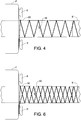
- Winding step 66 is illustrated by Figs. 4-6 .
- Fiber tow 30 is helically wound around mandrel M so as to approach end sleeve 22 in an axial direction, as shown in Fig. 4 .
- the helical winding continues until fiber tow 30 is wound around stem 24 and reaches flange layer 26.
- fiber tow 30 is wound around two of the plurality of eyelet forms E as illustrated in Fig. 5A . More specifically, fiber tow 30 departs from stem 24 and is wound partially around a first one of the eyelet forms E1.
- fiber tow 30 may have an outer tangential approach to the first eyelet form E1. Fiber tow 30 departs from first eyelet form E1, is wound partially around a second one of the eyelet forms E2 and proceeds back to stem 24 of end sleeve 22. As shown in Fig. 5A , fiber tow 30 may have an inner tangential approach to second eyelet form E2, and the fiber tow leaving second eyelet form E2 may cross the fiber tow approaching second eyelet form E2 when viewed in the axial direction toward flange layer 26. Winding step 66 continues by helically winding fiber tow 30 around stem 24 and mandrel M in an axial direction away from flange layer 26.
- another end sleeve 22 may be provided on mandrel M at a location corresponding to an opposite end of torque tube 10, and the winding pattern described above may be repeated in mirror-image fashion as fiber tow 30 approaches the opposing end sleeve. Helical winding continues back toward the first end sleeve 22. Once fiber tow 30 reaches flange layer 26, the eyelet winding pattern described above for first and second eyelet forms E1 and E2 is repeated for second eyelet form E2 and a third eyelet form E3 as illustrated in Fig. 5B . Fiber tow 30 departs from stem 24 and is wound partially around second eyelet form E2. Fiber tow 30 may have an outer tangential approach to second eyelet form E2.
- Fiber tow 30 departs from second eyelet form E2, is wound partially around third eyelet form E3, and proceeds back to stem 24 of end sleeve 22. As shown in Fig. 5B , fiber tow 30 may have an inner tangential approach to third eyelet form E3, and the fiber tow leaving third eyelet form E3 may cross the fiber tow approaching third eyelet form E3 when viewed in the axial direction toward flange layer 26.
- Helical winding then continues axially along stem 24 and mandrel M away from depicted end sleeve 22, and a mirror image winding pattern may be formed at the opposite end before fiber tow 30 is again helically wound around mandrel M back toward the depicted end sleeve 22.
- the eyelet winding pattern described above is repeated for third eyelet form E3 and a fourth eyelet form E4 as illustrated in Fig. 5C .
- Fiber tow 30 departs from stem 24 and is wound partially around third eyelet form E3.
- Fiber tow 30 may have an outer tangential approach to third eyelet form E3.
- Fiber tow 30 departs from third eyelet form E3 and is wound partially around fourth eyelet form E4 before returning to stem 24 of end sleeve 22.
- Fiber tow 30 may have an inner tangential approach to fourth eyelet form E4, and the fiber tow leaving fourth eyelet form E4 may cross the fiber tow approaching fourth eyelet form E4 when viewed in the axial direction toward flange layer 26.
- Fiber tow 30 is helically wound toward the opposite end, where the eyelet form winding pattern may be repeated in mirror image fashion, and is then helically wound back toward the depicted end sleeve 22. Once fiber tow 30 returns to flange layer 26, the eyelet winding pattern described above is repeated for fourth eyelet form E4 and a first eyelet form E1 as illustrated in Fig. 5D .
- Fiber tow 30 departs from stem 24 and is wound partially around fourth eyelet form E4.
- Fiber tow 30 may have an outer tangential approach to fourth eyelet form E4.
- Fiber tow 30 departs from fourth eyelet form E4 and is wound partially around first eyelet form E1 before returning to stem 24.
- Fiber tow 30 may have an inner tangential approach to first eyelet form E1, and the fiber tow leaving first eyelet form E1 may cross the fiber tow approaching first eyelet form E1 when viewed in the axial direction toward flange layer 26.
- the winding pattern described above is continued in repeating fashion until material is built up to form end couplings 14 and tube portion 12.
- the helical winding angle of fiber tow 30 may be varied during the winding step to achieve desired strength and flexural characteristics.
- Winding of the fiber tow may be performed using a conventional machine tool operated to rotate mandrel M and end fixtures F about their common longitudinal axis A in the manner of a lathe while a fiber tow feeder is reciprocated back and forth in the axial direction to feed fiber tow to the rotating assembly to achieve a predetermined winding pattern as the fiber tow is taken up by the rotating assembly.
- a fiber-wrapped assembly is formed that includes the mandrel M, end fixtures F including eyelet forms E1 through E4, end sleeves 22, and the wrapped fiber tow 30.
- Step 70 represents a decision block for branching flow depending upon whether or not prepreg fiber tow is used. If prepreg fiber tow is used, the wound fiber tow 30 and end sleeves 22 already include matrix resin in a partially cured B stage condition. In that case, the manufacturing method proceeds directly to curing step 78. If dry fiber tow is used, a resin matrix must be added to wound fiber tow 30 and woven end sleeves 22 by performing a resin infusion step 74 as known in the art of composite manufacturing, and then flow proceeds to curing step 78.
- the next step 78 is curing the resin matrix containing the wound fiber tow 30 and woven fiber end sleeves 22 until the resin is fully cured to a C stage condition.
- the composite assembly Prior to curing, the composite assembly may be shrink-wrapped with a shrink-wrap tape, or vacuum bagged to remove volatiles and trapped air as is known in the art of composite manufacturing. Curing may be performed at an elevated temperature by placing the assembly in an oven. Alternatively, curing may be performed in an autoclave. The curing protocol will depend upon the size and configuration of torque tube 10, and the type of resin and fiber tow used. After the resin and fiber tow material is fully cured, the assembly is removed from the oven or autoclave, and the shrink wrapping or vacuum bag is removed.
- step 82 eyelet forms E1 through E4 and end fixtures F are removed, and mandrel M is withdrawn by sliding it axially out of the assembly.
- the remaining structure comprises an all-composite torque tube 10.
- the all-composite torque tube may be in finished form without metal eyelets in bolt holes 18.
- eyelets 20 may be installed in an optional step 86.
- Eyelets 20 may be two-piece metal eyelets positioned through bolt holes 18 and crimped using a crimping tool.
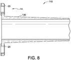
- Torque tube 110 is formed in a manner generally similar to torque tube 10 of the first embodiment, except that pre-woven end sleeves 22 are not used in forming end couplings 14. Instead, the entire composite structure of torque tube 110, including end fittings 14, is formed completely by winding fiber tow 130 directly around mandrel M and around the eyelet forms E held by fixture F. As in the first embodiment, metallic eyelets 20 may be provided to protect bolt holes 18.
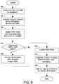
- a method of manufacturing torque tube 110 in accordance with the second embodiment is illustrated by the flow diagram of Fig. 9 .
- an initial step 150 at least one end fixture F is positioned on mandrel M.
- Step 154 involves inserting a plurality of eyelet forms E respectively into the plurality of openings FO in end fixture F.
- fiber tow 130 is wound around mandrel M and eyelet forms E. The same winding pattern described above in connection with step 66 of the first embodiment may be used for the second embodiment. If fiber tow 130 is prepreg fiber tow, decision step 162 advances flow to curing step 170. If fiber tow 130 is dry fiber tow, then decision step 162 directs flow to resin infusion step 166 before flow proceeds to curing step 170.
- the eyelet forms E, end fixture F and mandrel M are removed in step 174.
- the remaining structure comprises an all-composite torque tube 110.
- the all-composite torque tube may be in finished form without metal eyelets 20, or metal eyelets 20 may be installed in optional step 178 to protect and reinforce bolt holes 18.
- Figs. 10 and 11 illustrate a torque tube 210 and manufacturing method in accordance with a third embodiment of the present invention.
- Torque tube 210 is formed in a manner generally similar to torque tube 10 of the first embodiment, except that pre-woven end sleeves 22 are replaced by a modified end sleeve 222 having a stem 224 that grows radially and merges with an axially thickened flange 226 to form end couplings 14.
- each end coupling 14 is formed completely by pre-woven end sleeve 222, and tube portion 12 is formed by winding a fiber tow 230 around mandrel M and part of stem 224.
- a method of manufacturing torque tube 210 in accordance with the third embodiment not claimed in the present invention is illustrated by the flow diagram of Fig. 11 .
- an initial step 250 at least one pre-woven end sleeve 222 is provided.
- end sleeve 222 is placed on a cylindrical mandrel M.
- Step 258 represents an optional step wherein metal eyelets 20 are installed in bolt holes 228.
- step 262 fiber tow 230 is wound around mandrel M and stem 224 of end sleeve 222.
- the winding step 262 is simplified relative to the previous embodiments and involves helical winding back and forth along mandrel M.
- decision step 266 advances flow to curing step 274. If fiber tow 230 is dry fiber tow, then decision step 266 directs flow to resin infusion step 270 before flow proceeds to curing step 274. After curing of end sleeve 222 and wound fiber tow 230 is completed, mandrel M is removed in step 278.
- the remaining structure comprises an all-composite torque tube 210 having optional metal eyelets 20.
Landscapes
- Engineering & Computer Science (AREA)
- Mechanical Engineering (AREA)
- Chemical & Material Sciences (AREA)
- Composite Materials (AREA)
- General Engineering & Computer Science (AREA)
- Aviation & Aerospace Engineering (AREA)
- Textile Engineering (AREA)
- Ocean & Marine Engineering (AREA)
- Automation & Control Theory (AREA)
- Physics & Mathematics (AREA)
- Health & Medical Sciences (AREA)
- Oral & Maxillofacial Surgery (AREA)
- Thermal Sciences (AREA)
- Moulding By Coating Moulds (AREA)
Description
- The present invention relates generally to torque tubes (sometimes referred to as torque shafts) used on an aircraft utility or flight control drive line, or on any drive line that requires a torque tube for transmitting torque.
- A torque tube transmits static and dynamic torsional loads in power transmission applications. For example, torque tubes are commonly used in aircraft to provide power transmission for actuating and braking flight control surfaces, e.g. flaps and slats, and for actuating aircraft doors and door latches. Each end of a torque tube may be provided with a coupling feature configured for mechanically coupling the torque tube to another transmission mechanism in the drive line. For example, one or both ends of a torque tube may include a flange having an array or pattern of bolt holes used for coupling.
- So-called "composite" torque tubes made by helically winding or wrapping carbon fiber tow around a cylindrical mandrel are widely used in the aircraft industry in part because they are lighter than metal torque tubes yet still meet critical strength requirements. Composite torque tubes also offer improved flexural rigidity and torsional rigidity. However, because the coupling features at the ends of the torque tube differ from and are more complex than the straight length of the torque tube between the ends, the coupling features are not formed of wrapped composite material. Instead, it is known to manufacture a metallic end fitting that includes the coupling feature, and form the torque tube as a hybrid assembly having a pair of metal end fittings connected by a straight tube of wrapped composite material.. In this regard, see
U.S. Patent Nos. 7,335,108 (Lin e al .);7,419,435 (Borges et al. );7,682,256 (Brace et al. );7,874,925 (Dewhirst ); and8,025,580 (Genot et al. ). The metal end fittings add weight, and it is a challenge to ensure that the junction between the composite material and each metal end fitting is reliable and not prone to failure under loading. -
U.S. Patent No. 3,651,661 (Darrow) , teaches making a composite torque tube having typical bolt-hole flanges by laying alternating plies of composite fabric on a cylindrical mandrel. The flanges are made by folding out fingers or strips provided in the fabric plies. This patent does not teach winding fiber tow. -
U.S. Patent No. 5,397,272 (Smiley et al. ) describes an all-composite torque tube that teaches wrapping fiber around an arbor and integrally forming two yoke lugs of a universal joint at an end of the tube. The lugs extend parallel to one another in an axial direction of the torque tube and include respective holes aligned with one another along a diametric axis for receiving a coupling member of the universal joint. - Outside the torque tube art,
U.S. Patent No. 8,118,958 (Lunin et al. ) teaches a method for manufacturing an output arm for a rotary actuator by winding a composite fiber filament about a pair of metal eyelets and a metal gear insert. The eyelets and gear insert are supported on a fixture during winding. The wound filament is then infused with resin and the resin is cured. The fixture is removed to yield a finished actuator arm. - Methods for manufacturing a composite torque tube are also described by
DE4414384 andUS2011/192528 . - A need remains for an all-composite torque tube having flanges with bolt holes at its opposite ends, wherein the torque tube is economical to manufacture and does not require metal end fittings.
- The present invention provides a method for manufacturing a lightweight, all-composite torque tube at low-cost that involves a single structural curing step. The resulting torque tube has no torque-transmitting joints between composite material and metal, and is highly reliable.
- Thus according to the present invention there is provided a method as defined in claim 1. Optionally, metal eyelets may be installed to reinforce the bolt holes of the flange.
- According to one aspect of the present invention there is provided a method as defined in claim 7.
- The nature and mode of operation of the present invention will now be more fully described in the following detailed description of the invention taken with the accompanying drawing figures, in which:
-
Fig. 1 is an orthogonal view of a composite torque tube generally embodying the present invention; -
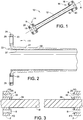
Fig. 2 is a longitudinal cross-sectional view showing an end portion of a composite torque tube formed in accordance with a first embodiment of the present invention; -
Fig. 3 is a longitudinal cross-sectional view illustrating a manufacturing setup for making the composite torque tube shown inFig. 2 ; -
Fig. 4 is a view of one end of the manufacturing setup shown inFig. 3 , illustrating a helical winding step of a method for manufacturing the composite torque tube shown inFig. 2 ; -
Fig. 5A is a view looking axially toward an end fixture of the manufacturing setup, illustrating a first eyelet winding step of the manufacturing method; -
Fig. 5B is a view similar to that ofFig. 5A , illustrating a second eyelet winding step of the manufacturing method; -
Fig. 5C is a view similar to that ofFig. 5A , illustrating a third eyelet winding step of the manufacturing method; -
Fig. 5D is a view similar to that ofFig. 5A , illustrating a fourth eyelet winding step of the manufacturing method; -
Fig. 6 is a view similar to that ofFig. 4 , illustrating a reverse helical winding step of the manufacturing method; -
Fig. 7 is a flow diagram illustrating a method of making the composite torque tube shown inFig. 1 ; -
Fig. 8 is a longitudinal cross-sectional view showing an end portion of a composite torque tube formed in accordance with a second embodiment of the present invention; -
Fig. 9 is a flow diagram illustrating a method of making the composite torque tube shown inFig. 8 ; -
Fig. 10 is a longitudinal cross-sectional view showing an end portion of a composite torque tube formed in accordance with a third embodiment not claimed in the present invention; and -
Fig. 11 is a flow diagram illustrating a method of making the composite torque tube shown inFig. 10 . -
Fig. 1 depicts acomposite torque tube 10 formed by a method of the present invention.Composite torque tube 10 generally comprises a pair ofend couplings 14 connected by anintermediate tube portion 12. Reference character A denotes a longitudinal axis oftorque tube 10. Eachend coupling 14 includes aflange 16 that extends radially outward relative to an outer cylindrical surface oftube portion 12, and a plurality ofbolt holes 18 throughflange 16 for use in attachingend coupling 14 to another part of a transmission drive system. In the embodiments described herein, eachend coupling 14 has fourbolt holes 18, however more or fewer bolt holes may be provided depending upon the particular end use application and design requirements. A two-piece metal eyelet 20 may optionally be arranged in eachbolt hole 18 to reinforce and protect the inner surface of the bolt hole from the bolt's clamping force.Torque tube 10 is completely formed of fiber-reinforced composite material, with the exception ofoptional metal eyelets 20. -
Fig. 2 shows one end portion ofcomposite torque tube 10 in greater detail to illustrate a first embodiment of the present invention. As will be described below,composite torque tube 10 of the first embodiment is formed using apre-woven end sleeve 22 at each end, and a fiber tow winding 30 merging with eachend sleeve 22. The constituent fibers ofend sleeves 22 and fiber tow winding 30 reside in a thermosetting resin matrix that cures fully at an elevated temperature by undergoing an irreversible chemical reaction in which cross-linking of the resin molecules converts the resin to a stable solid (the C stage), whereby curing integrates theend sleeves 22 and fiber tow winding 30 into a solid structural composite material. The fibers used to weaveend sleeves 22, and the fibers in fiber tow winding 30, may be pre-impregnated with the thermosetting resin matrix that is partially cured to a B stage of curing to provide a composite fiber material that is thickened and somewhat tacky in comparison to uncured "wet" layup material. As an alternative to using "prepreg" fiber material, dry fiber tow may be used to formend sleeves 22 and winding 30, and the constituent fibers may be vacuum infused after weaving and winding with a thermosetting resin matrix. The fibers may include, for example, carbon fibers, glass fibers, aramid fibers, boron fibers, and/or ceramic fibers. - Each
end sleeve 22 is configured to include anaxially extending stem 24, a radiallyenlarged flange layer 26 at a distal end of the stem, apassage 27 through theflange layer 26 and thestem 24 for receiving an end portion of a mandrel M (seeFig. 3 ), and a plurality of bolt holes 28 throughflange layer 26. - A method of manufacturing
torque tube 10 in accordance with the first embodiment will now be described with reference to the flow diagram ofFig. 7 and with additional reference toFigs. 3-6 . In aninitial step 50, at least onepre-woven end sleeve 22 is provided. Instep 54,end sleeve 22 is placed on a cylindrical mandrel M. Next, in accordance withstep 58, an end fixture F is positioned on mandrel M in abutment againstflange layer 26 ofend sleeve 22. End fixture F includes a plurality of openings FO respectively aligned with the plurality of bolt holes 28 ofend sleeve 22. Manufacturing setup also includesstep 62 of inserting a plurality of eyelet forms E respectively through the plurality of bolt holes 28 ofend sleeve 22 and into the plurality of openings FO in end fixture F. This arrangement may be seen, for example, inFig. 3 . - The method continues at
step 66 with windingfiber tow 30 around mandrel M, thestem 24 of theend sleeve 22, and the plurality of eyelet formsE. Winding step 66 is illustrated byFigs. 4-6 .Fiber tow 30 is helically wound around mandrel M so as to approachend sleeve 22 in an axial direction, as shown inFig. 4 . The helical winding continues untilfiber tow 30 is wound aroundstem 24 and reachesflange layer 26. Then,fiber tow 30 is wound around two of the plurality of eyelet forms E as illustrated inFig. 5A . More specifically,fiber tow 30 departs fromstem 24 and is wound partially around a first one of the eyelet forms E1. As may be seen,fiber tow 30 may have an outer tangential approach to the first eyelet form E1.Fiber tow 30 departs from first eyelet form E1, is wound partially around a second one of the eyelet forms E2 and proceeds back to stem 24 ofend sleeve 22. As shown inFig. 5A ,fiber tow 30 may have an inner tangential approach to second eyelet form E2, and the fiber tow leaving second eyelet form E2 may cross the fiber tow approaching second eyelet form E2 when viewed in the axial direction towardflange layer 26. Windingstep 66 continues by helically windingfiber tow 30 aroundstem 24 and mandrel M in an axial direction away fromflange layer 26. - As may be understood, another
end sleeve 22 may be provided on mandrel M at a location corresponding to an opposite end oftorque tube 10, and the winding pattern described above may be repeated in mirror-image fashion asfiber tow 30 approaches the opposing end sleeve. Helical winding continues back toward thefirst end sleeve 22. Oncefiber tow 30 reachesflange layer 26, the eyelet winding pattern described above for first and second eyelet forms E1 and E2 is repeated for second eyelet form E2 and a third eyelet form E3 as illustrated inFig. 5B .Fiber tow 30 departs fromstem 24 and is wound partially around second eyelet form E2.Fiber tow 30 may have an outer tangential approach to second eyelet form E2.Fiber tow 30 departs from second eyelet form E2, is wound partially around third eyelet form E3, and proceeds back to stem 24 ofend sleeve 22. As shown inFig. 5B ,fiber tow 30 may have an inner tangential approach to third eyelet form E3, and the fiber tow leaving third eyelet form E3 may cross the fiber tow approaching third eyelet form E3 when viewed in the axial direction towardflange layer 26. - Helical winding then continues axially along
stem 24 and mandrel M away from depictedend sleeve 22, and a mirror image winding pattern may be formed at the opposite end beforefiber tow 30 is again helically wound around mandrel M back toward the depictedend sleeve 22. Oncefiber tow 30 returns toflange layer 26, the eyelet winding pattern described above is repeated for third eyelet form E3 and a fourth eyelet form E4 as illustrated inFig. 5C .Fiber tow 30 departs fromstem 24 and is wound partially around third eyelet form E3.Fiber tow 30 may have an outer tangential approach to third eyelet form E3.Fiber tow 30 departs from third eyelet form E3 and is wound partially around fourth eyelet form E4 before returning to stem 24 ofend sleeve 22.Fiber tow 30 may have an inner tangential approach to fourth eyelet form E4, and the fiber tow leaving fourth eyelet form E4 may cross the fiber tow approaching fourth eyelet form E4 when viewed in the axial direction towardflange layer 26. -
Fiber tow 30 is helically wound toward the opposite end, where the eyelet form winding pattern may be repeated in mirror image fashion, and is then helically wound back toward the depictedend sleeve 22. Oncefiber tow 30 returns toflange layer 26, the eyelet winding pattern described above is repeated for fourth eyelet form E4 and a first eyelet form E1 as illustrated inFig. 5D .Fiber tow 30 departs fromstem 24 and is wound partially around fourth eyelet form E4.Fiber tow 30 may have an outer tangential approach to fourth eyelet form E4.Fiber tow 30 departs from fourth eyelet form E4 and is wound partially around first eyelet form E1 before returning tostem 24.Fiber tow 30 may have an inner tangential approach to first eyelet form E1, and the fiber tow leaving first eyelet form E1 may cross the fiber tow approaching first eyelet form E1 when viewed in the axial direction towardflange layer 26. - As will be understood, the winding pattern described above is continued in repeating fashion until material is built up to form
end couplings 14 andtube portion 12. Those skilled in the art will recognize that the helical winding angle offiber tow 30 may be varied during the winding step to achieve desired strength and flexural characteristics. Winding of the fiber tow may be performed using a conventional machine tool operated to rotate mandrel M and end fixtures F about their common longitudinal axis A in the manner of a lathe while a fiber tow feeder is reciprocated back and forth in the axial direction to feed fiber tow to the rotating assembly to achieve a predetermined winding pattern as the fiber tow is taken up by the rotating assembly. When the fibertow wrapping step 66 is completed, a fiber-wrapped assembly is formed that includes the mandrel M, end fixtures F including eyelet forms E1 through E4, endsleeves 22, and the wrappedfiber tow 30. -
Step 70 represents a decision block for branching flow depending upon whether or not prepreg fiber tow is used. If prepreg fiber tow is used, thewound fiber tow 30 and endsleeves 22 already include matrix resin in a partially cured B stage condition. In that case, the manufacturing method proceeds directly to curingstep 78. If dry fiber tow is used, a resin matrix must be added to woundfiber tow 30 andwoven end sleeves 22 by performing aresin infusion step 74 as known in the art of composite manufacturing, and then flow proceeds to curingstep 78. - The
next step 78 is curing the resin matrix containing thewound fiber tow 30 and wovenfiber end sleeves 22 until the resin is fully cured to a C stage condition. Prior to curing, the composite assembly may be shrink-wrapped with a shrink-wrap tape, or vacuum bagged to remove volatiles and trapped air as is known in the art of composite manufacturing. Curing may be performed at an elevated temperature by placing the assembly in an oven. Alternatively, curing may be performed in an autoclave. The curing protocol will depend upon the size and configuration oftorque tube 10, and the type of resin and fiber tow used. After the resin and fiber tow material is fully cured, the assembly is removed from the oven or autoclave, and the shrink wrapping or vacuum bag is removed. - In
step 82, eyelet forms E1 through E4 and end fixtures F are removed, and mandrel M is withdrawn by sliding it axially out of the assembly. The remaining structure comprises an all-composite torque tube 10. The all-composite torque tube may be in finished form without metal eyelets in bolt holes 18. Alternatively, if metal eyelets 20 are desired to protect and reinforcebolt holes 18, eyelets 20 may be installed in anoptional step 86.Eyelets 20 may be two-piece metal eyelets positioned through bolt holes 18 and crimped using a crimping tool. - Attention is now directed to
Figs. 8 and9 illustrating atorque tube 110 and manufacturing method in accordance with a second embodiment of the present invention.Torque tube 110 is formed in a manner generally similar totorque tube 10 of the first embodiment, except thatpre-woven end sleeves 22 are not used in formingend couplings 14. Instead, the entire composite structure oftorque tube 110, includingend fittings 14, is formed completely by windingfiber tow 130 directly around mandrel M and around the eyelet forms E held by fixture F. As in the first embodiment,metallic eyelets 20 may be provided to protect bolt holes 18. - A method of manufacturing
torque tube 110 in accordance with the second embodiment is illustrated by the flow diagram ofFig. 9 . In aninitial step 150, at least one end fixture F is positioned onmandrel M. Step 154 involves inserting a plurality of eyelet forms E respectively into the plurality of openings FO in end fixture F. Next, instep 158,fiber tow 130 is wound around mandrel M and eyelet forms E. The same winding pattern described above in connection withstep 66 of the first embodiment may be used for the second embodiment. Iffiber tow 130 is prepreg fiber tow,decision step 162 advances flow to curingstep 170. Iffiber tow 130 is dry fiber tow, thendecision step 162 directs flow toresin infusion step 166 before flow proceeds to curingstep 170. After curing is completed, the eyelet forms E, end fixture F and mandrel M are removed instep 174. The remaining structure comprises an all-composite torque tube 110. The all-composite torque tube may be in finished form withoutmetal eyelets 20, ormetal eyelets 20 may be installed inoptional step 178 to protect and reinforce bolt holes 18. -
Figs. 10 and11 illustrate atorque tube 210 and manufacturing method in accordance with a third embodiment of the present invention.Torque tube 210 is formed in a manner generally similar totorque tube 10 of the first embodiment, except thatpre-woven end sleeves 22 are replaced by a modifiedend sleeve 222 having astem 224 that grows radially and merges with an axially thickenedflange 226 to formend couplings 14. Thus, intorque tube 210, eachend coupling 14 is formed completely bypre-woven end sleeve 222, andtube portion 12 is formed by winding afiber tow 230 around mandrel M and part ofstem 224. - A method of manufacturing
torque tube 210 in accordance with the third embodiment not claimed in the present invention is illustrated by the flow diagram ofFig. 11 . In aninitial step 250, at least onepre-woven end sleeve 222 is provided. Instep 254,end sleeve 222 is placed on a cylindricalmandrel M. Step 258 represents an optional step whereinmetal eyelets 20 are installed in bolt holes 228. Next, instep 262,fiber tow 230 is wound around mandrel M and stem 224 ofend sleeve 222. For the third embodiment, the windingstep 262 is simplified relative to the previous embodiments and involves helical winding back and forth along mandrel M.If fiber tow 230 is prepreg fiber tow,decision step 266 advances flow to curingstep 274. Iffiber tow 230 is dry fiber tow, thendecision step 266 directs flow toresin infusion step 270 before flow proceeds to curingstep 274. After curing ofend sleeve 222 and woundfiber tow 230 is completed, mandrel M is removed instep 278. The remaining structure comprises an all-composite torque tube 210 having optional metal eyelets 20. - While the invention has been described in connection with exemplary embodiments, the detailed description is not intended to limit the scope of the invention to the particular forms set forth. The invention is intended to cover such alternatives, modifications and equivalents of the described embodiment as may be included within the scope of the invention.
Claims (9)
- A method of manufacturing a composite torque tube (10, 110), the method comprising the steps of:providing a cylindrical mandrel (M);positioning an end fixture (F) on the mandrel (M), the end fixture (F) including a backing surface radially enlarged relative to an outer surface of the mandrel (M) and a plurality of openings (FO) through the backing surface;inserting a plurality of eyelet forms (E) respectively into the plurality of openings (FO) of the end fixture (F);winding a fiber tow around (30, 130) the mandrel (M) and the plurality of eyelet forms (E);infusing the wound fiber tow (30, 130) with a resin matrix, or using fiber tow pre-impregnated with a resin matrix in a B cure stage as the fiber tow (30, 130) for the winding step;curing the wound fiber tow (30, 130) to a C cure stage, thereby yielding a composite tube (10, 110) including an integral end flange (16) having a plurality of bolt holes (18); andremoving the eyelet forms (E), the end fixture (F), and the mandrel (M) from the composite tube (10, 110);wherein the step of winding the fiber tow (30) includes, in ordered sequence:helically winding the fiber tow (30, 130) around the mandrel (M) in an axial direction toward the flange layer (26);winding the fiber tow (30, 130) partially around a first one (E1) of the eyelet forms (E);winding the fiber tow (30, 130) partially around a second one (E2) of the eyelet forms (E) such that the fiber tow (30, 130) leaving the second eyelet form (E2) crosses the fiber tow (30, 130) approaching the second eyelet form (E2) when viewed in the axial direction toward the flange layer (26); andhelically winding the fiber tow (30, 130) around the mandrel (M) in an axial direction away from the flange layer.
- The method according to claim 1, further comprising the steps of:providing a woven end sleeve (22) including an axially extending stem (24), a radially enlarged flange layer (26) at a distal end of the stem (24), a passage (27) through the flange layer (26) and the stem (24) for receiving an end portion of the mandrel (M), and a plurality of bolt holes (28) through the flange layer (26);placing the end sleeve (20) on the mandrel (M) such that the flange layer (26) of the end sleeve (24) is in abutment against the backing surface of the end fixture (F), wherein the plurality of eyelet forms (E) are inserted respectively through the plurality of bolt holes (28) of the end sleeve (22) and into the plurality of openings (FO) of the end fixture (F); andinfusing the end sleeve (22) with a resin matrix, or using fiber tow (30) pre-impregnated with a resin matrix in a B cure stage to weave the end sleeve (22);wherein the winding step includes winding the fiber tow (30) around the stem (24) of the end sleeve (22);wherein the curing step includes curing the end sleeve (22) to a C cure stage along with the wound fiber tow (30).
- The method according to claim 1, further comprising the step of installing a plurality of metal eyelets (20) respectively in the plurality of bolt holes (28) of the integral end flange (26).
- The method according to claim 2, further comprising the step of installing a plurality of metal eyelets (20) respectively in the plurality of bolt holes (28) of the integral end flange (26).
- The method according to claim 2, wherein the step of winding the fiber tow (30) further comprising the steps of:helically winding the fiber tow (30) around the stem (24) of the sleeve (20) in an axial direction toward the flange layer (26) after winding the fiber tow (30) around the mandrel (M) in an axial direction towards the flange layer (26); andhelically winding the fiber tow (30) around the stem (24) of the sleeve (20) in an axial direction away from the flange layer (26) after winding the fiber tow (30) around the mandrel (M) in an axial direction away from the flange layer (26).
- The method according to claim 1 or claim 5, wherein the fiber tow (30) has an outer tangential approach to the first one (E1) of the eyelet forms (E) and an inner tangential approach to the second one (E2) of the eyelet forms (E).
- A method of manufacturing a composite torque tube (10), the method comprising the steps of:providing a cylindrical mandrel (M);providing a woven end sleeve (22) including an axially extending stem (24), a radially enlarged flange (26) at a distal end of the stem (24), a passage (27) through the flange (26) and the stem (24) for receiving an end portion of the mandrel (M), and a plurality of bolt holes (28) through the flange (26);placing the end sleeve (28) on a mandrel (M);winding a fiber tow (30) around the mandrel (M) and the stem (24) of the end sleeve (22);infusing the wound fiber tow (30) and the end sleeve (22) with a resin matrix, or using fiber tow (30) pre-impregnated with a resin matrix in a B cure stage as the fiber tow (30) for the winding step and to weave the end sleeve (22);curing the fiber tow (30) and the end sleeve (22) to a C cure stage, thereby yielding a composite tube (10) including an integral end flange (16) having a plurality of bolt holes (18); andremoving the mandrel (M).
- The method according to claim 7, further comprising the step of positioning a plurality of metal eyelets (20) respectively in the plurality of bolt holes (28) of the end sleeve (22) prior to the step of curing.
- The method according to claim 7, wherein the step of winding the fiber tow (30) includes, in ordered sequence:helically winding the fiber tow (30) around the mandrel (M) and the stem (24) of the end sleeve (22) in an axial direction toward the flange (26) of the end sleeve (22); andhelically winding the fiber tow (30) around the stem (24) of the end sleeve (22) and the mandrel (M) in an axial direction away from the flange (26) of the end sleeve (22).
Applications Claiming Priority (2)
| Application Number | Priority Date | Filing Date | Title |
|---|---|---|---|
| US14/996,922 US9937671B2 (en) | 2016-01-15 | 2016-01-15 | All-composite torque tube with metal eyelets |
| PCT/US2016/068182 WO2017123399A1 (en) | 2016-01-15 | 2016-12-22 | All-composite torque tube with metal eyelets |
Publications (3)
| Publication Number | Publication Date |
|---|---|
| EP3402656A1 EP3402656A1 (en) | 2018-11-21 |
| EP3402656A4 EP3402656A4 (en) | 2019-09-11 |
| EP3402656B1 true EP3402656B1 (en) | 2020-09-30 |
Family
ID=59311636
Family Applications (1)
| Application Number | Title | Priority Date | Filing Date |
|---|---|---|---|
| EP16885428.9A Active EP3402656B1 (en) | 2016-01-15 | 2016-12-22 | All-composite torque tube with metal eyelets |
Country Status (8)
| Country | Link |
|---|---|
| US (1) | US9937671B2 (en) |
| EP (1) | EP3402656B1 (en) |
| JP (1) | JP6660470B2 (en) |
| KR (1) | KR102044644B1 (en) |
| CN (1) | CN108472882B (en) |
| BR (1) | BR112018013037B1 (en) |
| ES (1) | ES2827779T3 (en) |
| WO (1) | WO2017123399A1 (en) |
Families Citing this family (13)
| Publication number | Priority date | Publication date | Assignee | Title |
|---|---|---|---|---|
| EP3480479B1 (en) | 2017-11-01 | 2024-10-30 | Crompton Technology Group Limited | Transmission shaft |
| EP3608095B1 (en) | 2018-08-10 | 2026-05-06 | Crompton Technology Group Limited | Composite connectors and methods of manufacturing the same |
| EP3608089B1 (en) | 2018-08-10 | 2022-10-12 | Crompton Technology Group Limited | Composite connector and method of manufacturing the same |
| EP3608091B1 (en) | 2018-08-10 | 2025-10-01 | Crompton Technology Group Limited | Composite connector and method of manufacturing the same |
| EP3608094B1 (en) | 2018-08-10 | 2024-09-25 | Crompton Technology Group Limited | Composite connector and method of manufacturing the same |
| EP3608092B1 (en) | 2018-08-10 | 2023-06-28 | Crompton Technology Group Limited | Composite connector and method of manufacturing the same |
| EP3608093B1 (en) * | 2018-08-10 | 2024-04-17 | Crompton Technology Group Limited | Composite connector and method of manufacturing the same |
| US10988243B2 (en) * | 2019-03-15 | 2021-04-27 | Bell Textron Inc. | Tension-torsion strap |
| EP3972897B1 (en) | 2019-05-22 | 2023-04-26 | Moog Inc. | Preloaded torque shaft and the flight control driveline made therewith |
| EP3805623B1 (en) | 2019-10-07 | 2023-11-29 | Crompton Technology Group Limited | Fibre reinforced polymer composite pipes and method of making thereof |
| EP4001677B1 (en) * | 2020-11-19 | 2022-11-09 | AIRBUS HELICOPTERS DEUTSCHLAND GmbH | A drive shaft with an integrated flange |
| CN113232329B (en) * | 2021-03-31 | 2022-09-20 | 成都飞机工业(集团)有限责任公司 | Preparation method of integrated composite material conduit with flange plate |
| CN115648600B (en) * | 2022-12-13 | 2023-03-21 | 太原理工大学 | A method for automatic winding of multi-bundle fibers |
Family Cites Families (22)
| Publication number | Priority date | Publication date | Assignee | Title |
|---|---|---|---|---|
| US3651661A (en) | 1970-02-02 | 1972-03-28 | United Aircraft Corp | Composite shaft with integral end flange |
| GB1584151A (en) * | 1976-04-15 | 1981-02-04 | Vredestein Nv | Highpressure filament reinforced hose having integral filament-bound couplings and method of making same |
| US4118262A (en) * | 1976-05-21 | 1978-10-03 | Brunswick Corporation | Longitudinal load carrying method for fiber reinforced filament wound structures |
| US4851065A (en) | 1986-01-17 | 1989-07-25 | Tyee Aircraft, Inc. | Construction of hollow, continuously wound filament load-bearing structure |
| JPH03161326A (en) * | 1989-11-20 | 1991-07-11 | Mitsubishi Electric Corp | Pipe fitted with flange made of fiber reinforced composite material and preparation thereof |
| US5091029A (en) | 1991-01-15 | 1992-02-25 | United Technologies Corporation | Method of manufacturing a unitary, multi-legged helicopter rotor flexbeam made solely of composite materials |
| JPH05269868A (en) * | 1992-03-25 | 1993-10-19 | Sumitomo Metal Ind Ltd | Method for manufacturing perforated hollow composite material |
| US5397272A (en) | 1993-02-08 | 1995-03-14 | Pressure Technology, Inc. | Braided composite shaft with yoke member |
| JP3398455B2 (en) * | 1993-04-26 | 2003-04-21 | トヨタ自動車株式会社 | Drive shaft manufacturing method and drive shaft coupling device |
| JP3230411B2 (en) * | 1995-05-17 | 2001-11-19 | トヨタ自動車株式会社 | Manufacturing method of composite shaft |
| GB9622799D0 (en) * | 1996-11-01 | 1997-01-08 | Flight Refueling Ltd | A rotary power transmission shaft |
| US20020189749A1 (en) | 2000-05-18 | 2002-12-19 | Advanced Materials Corporation | Method for making a cover for a roll core having a multiple layer construction and having minimal residual stresses |
| CA2481730C (en) | 2002-04-19 | 2010-03-23 | Bell Helicopter Textron Inc. | Composite drive shaft with captured end adapters |
| GB2435317B (en) | 2006-01-17 | 2008-01-02 | Crompton Technology Group Ltd | Transmission shaft joint design |
| US7419435B2 (en) | 2006-03-09 | 2008-09-02 | Northrop Grumman Corporation | Composite torque tube captured end fitting |
| US8118958B2 (en) | 2006-04-28 | 2012-02-21 | Moog Inc. | Composite ring gear with metallic gear insert, and method of forming same |
| US7682256B2 (en) | 2006-09-13 | 2010-03-23 | Kop-Flex Inc. | Flange design for filament wound composite shaft |
| US20080157418A1 (en) * | 2006-12-27 | 2008-07-03 | Lee Alan Blanton | Methods for fabricating composite structures with flanges having tethered corners |
| FR2917474B1 (en) | 2007-06-18 | 2009-08-07 | Skf Aerospace France Soc Par A | SHAFT FOR TRANSMITTING MOVEMENTS AND / OR EFFORTS IN ROTATION |
| JP4263753B2 (en) | 2007-08-10 | 2009-05-13 | トヨタ自動車株式会社 | Manufacturing method of fiber-reinforced resin tubular member |
| DE102008056018A1 (en) * | 2008-11-05 | 2010-05-06 | Rolls-Royce Deutschland Ltd & Co Kg | Engine shaft for a gas turbine engine |
| GB201106794D0 (en) * | 2011-04-21 | 2011-06-01 | Rolls Royce Plc | A composite flange element |
-
2016
- 2016-01-15 US US14/996,922 patent/US9937671B2/en active Active
- 2016-12-22 WO PCT/US2016/068182 patent/WO2017123399A1/en not_active Ceased
- 2016-12-22 ES ES16885428T patent/ES2827779T3/en active Active
- 2016-12-22 CN CN201680078915.1A patent/CN108472882B/en not_active Expired - Fee Related
- 2016-12-22 EP EP16885428.9A patent/EP3402656B1/en active Active
- 2016-12-22 KR KR1020187017931A patent/KR102044644B1/en active Active
- 2016-12-22 BR BR112018013037-0A patent/BR112018013037B1/en not_active IP Right Cessation
- 2016-12-22 JP JP2018527979A patent/JP6660470B2/en not_active Expired - Fee Related
Non-Patent Citations (1)
| Title |
|---|
| None * |
Also Published As
| Publication number | Publication date |
|---|---|
| EP3402656A4 (en) | 2019-09-11 |
| KR20180087343A (en) | 2018-08-01 |
| CN108472882B (en) | 2021-01-15 |
| KR102044644B1 (en) | 2019-11-13 |
| ES2827779T3 (en) | 2021-05-24 |
| CN108472882A (en) | 2018-08-31 |
| US9937671B2 (en) | 2018-04-10 |
| JP6660470B2 (en) | 2020-03-11 |
| BR112018013037B1 (en) | 2022-03-22 |
| US20170203521A1 (en) | 2017-07-20 |
| BR112018013037A2 (en) | 2018-12-04 |
| WO2017123399A1 (en) | 2017-07-20 |
| EP3402656A1 (en) | 2018-11-21 |
| JP2019505405A (en) | 2019-02-28 |
Similar Documents
| Publication | Publication Date | Title |
|---|---|---|
| EP3402656B1 (en) | All-composite torque tube with metal eyelets | |
| EP3397451B1 (en) | Composite torque tube end fitting attachment method | |
| CA2925672C (en) | Hybrid metal-composite drive shaft unit and method of manufacturing the same | |
| US20180100538A1 (en) | Fibre Reinforced Polymer Matrix Composite Torque Tubes or Shafts | |
| US11873860B2 (en) | Transmission shaft | |
| US12152633B2 (en) | Composite drive shafts | |
| CA3064091A1 (en) | Hybrid metallic/composite tube design to transfer bending, axial, and flexural shear | |
| US20250282110A1 (en) | Carbon-fiber-reinforced resin cylinder for propeller shafts |
Legal Events
| Date | Code | Title | Description |
|---|---|---|---|
| STAA | Information on the status of an ep patent application or granted ep patent |
Free format text: STATUS: THE INTERNATIONAL PUBLICATION HAS BEEN MADE |
|
| PUAI | Public reference made under article 153(3) epc to a published international application that has entered the european phase |
Free format text: ORIGINAL CODE: 0009012 |
|
| STAA | Information on the status of an ep patent application or granted ep patent |
Free format text: STATUS: REQUEST FOR EXAMINATION WAS MADE |
|
| 17P | Request for examination filed |
Effective date: 20180524 |
|
| AK | Designated contracting states |
Kind code of ref document: A1 Designated state(s): AL AT BE BG CH CY CZ DE DK EE ES FI FR GB GR HR HU IE IS IT LI LT LU LV MC MK MT NL NO PL PT RO RS SE SI SK SM TR |
|
| AX | Request for extension of the european patent |
Extension state: BA ME |
|
| DAV | Request for validation of the european patent (deleted) | ||
| DAX | Request for extension of the european patent (deleted) | ||
| A4 | Supplementary search report drawn up and despatched |
Effective date: 20190813 |
|
| RIC1 | Information provided on ipc code assigned before grant |
Ipc: B29C 53/58 20060101ALI20190807BHEP Ipc: B29D 23/00 20060101ALI20190807BHEP Ipc: B29C 70/32 20060101AFI20190807BHEP Ipc: B29C 70/86 20060101ALI20190807BHEP |
|
| GRAP | Despatch of communication of intention to grant a patent |
Free format text: ORIGINAL CODE: EPIDOSNIGR1 |
|
| STAA | Information on the status of an ep patent application or granted ep patent |
Free format text: STATUS: GRANT OF PATENT IS INTENDED |
|
| INTG | Intention to grant announced |
Effective date: 20200504 |
|
| GRAS | Grant fee paid |
Free format text: ORIGINAL CODE: EPIDOSNIGR3 |
|
| GRAA | (expected) grant |
Free format text: ORIGINAL CODE: 0009210 |
|
| STAA | Information on the status of an ep patent application or granted ep patent |
Free format text: STATUS: THE PATENT HAS BEEN GRANTED |
|
| AK | Designated contracting states |
Kind code of ref document: B1 Designated state(s): AL AT BE BG CH CY CZ DE DK EE ES FI FR GB GR HR HU IE IS IT LI LT LU LV MC MK MT NL NO PL PT RO RS SE SI SK SM TR |
|
| REG | Reference to a national code |
Ref country code: GB Ref legal event code: FG4D Ref country code: CH Ref legal event code: EP |
|
| REG | Reference to a national code |
Ref country code: AT Ref legal event code: REF Ref document number: 1318374 Country of ref document: AT Kind code of ref document: T Effective date: 20201015 Ref country code: DE Ref legal event code: R096 Ref document number: 602016045205 Country of ref document: DE |
|
| REG | Reference to a national code |
Ref country code: IE Ref legal event code: FG4D |
|
| PG25 | Lapsed in a contracting state [announced via postgrant information from national office to epo] |
Ref country code: GR Free format text: LAPSE BECAUSE OF FAILURE TO SUBMIT A TRANSLATION OF THE DESCRIPTION OR TO PAY THE FEE WITHIN THE PRESCRIBED TIME-LIMIT Effective date: 20201231 Ref country code: NO Free format text: LAPSE BECAUSE OF FAILURE TO SUBMIT A TRANSLATION OF THE DESCRIPTION OR TO PAY THE FEE WITHIN THE PRESCRIBED TIME-LIMIT Effective date: 20201230 Ref country code: FI Free format text: LAPSE BECAUSE OF FAILURE TO SUBMIT A TRANSLATION OF THE DESCRIPTION OR TO PAY THE FEE WITHIN THE PRESCRIBED TIME-LIMIT Effective date: 20200930 Ref country code: SE Free format text: LAPSE BECAUSE OF FAILURE TO SUBMIT A TRANSLATION OF THE DESCRIPTION OR TO PAY THE FEE WITHIN THE PRESCRIBED TIME-LIMIT Effective date: 20200930 Ref country code: HR Free format text: LAPSE BECAUSE OF FAILURE TO SUBMIT A TRANSLATION OF THE DESCRIPTION OR TO PAY THE FEE WITHIN THE PRESCRIBED TIME-LIMIT Effective date: 20200930 Ref country code: BG Free format text: LAPSE BECAUSE OF FAILURE TO SUBMIT A TRANSLATION OF THE DESCRIPTION OR TO PAY THE FEE WITHIN THE PRESCRIBED TIME-LIMIT Effective date: 20201230 |
|
| REG | Reference to a national code |
Ref country code: AT Ref legal event code: MK05 Ref document number: 1318374 Country of ref document: AT Kind code of ref document: T Effective date: 20200930 |
|
| PG25 | Lapsed in a contracting state [announced via postgrant information from national office to epo] |
Ref country code: LV Free format text: LAPSE BECAUSE OF FAILURE TO SUBMIT A TRANSLATION OF THE DESCRIPTION OR TO PAY THE FEE WITHIN THE PRESCRIBED TIME-LIMIT Effective date: 20200930 Ref country code: RS Free format text: LAPSE BECAUSE OF FAILURE TO SUBMIT A TRANSLATION OF THE DESCRIPTION OR TO PAY THE FEE WITHIN THE PRESCRIBED TIME-LIMIT Effective date: 20200930 |
|
| REG | Reference to a national code |
Ref country code: NL Ref legal event code: MP Effective date: 20200930 |
|
| REG | Reference to a national code |
Ref country code: LT Ref legal event code: MG4D |
|
| PG25 | Lapsed in a contracting state [announced via postgrant information from national office to epo] |
Ref country code: CZ Free format text: LAPSE BECAUSE OF FAILURE TO SUBMIT A TRANSLATION OF THE DESCRIPTION OR TO PAY THE FEE WITHIN THE PRESCRIBED TIME-LIMIT Effective date: 20200930 Ref country code: PT Free format text: LAPSE BECAUSE OF FAILURE TO SUBMIT A TRANSLATION OF THE DESCRIPTION OR TO PAY THE FEE WITHIN THE PRESCRIBED TIME-LIMIT Effective date: 20210201 Ref country code: RO Free format text: LAPSE BECAUSE OF FAILURE TO SUBMIT A TRANSLATION OF THE DESCRIPTION OR TO PAY THE FEE WITHIN THE PRESCRIBED TIME-LIMIT Effective date: 20200930 Ref country code: LT Free format text: LAPSE BECAUSE OF FAILURE TO SUBMIT A TRANSLATION OF THE DESCRIPTION OR TO PAY THE FEE WITHIN THE PRESCRIBED TIME-LIMIT Effective date: 20200930 Ref country code: EE Free format text: LAPSE BECAUSE OF FAILURE TO SUBMIT A TRANSLATION OF THE DESCRIPTION OR TO PAY THE FEE WITHIN THE PRESCRIBED TIME-LIMIT Effective date: 20200930 Ref country code: SM Free format text: LAPSE BECAUSE OF FAILURE TO SUBMIT A TRANSLATION OF THE DESCRIPTION OR TO PAY THE FEE WITHIN THE PRESCRIBED TIME-LIMIT Effective date: 20200930 |
|
| REG | Reference to a national code |
Ref country code: ES Ref legal event code: FG2A Ref document number: 2827779 Country of ref document: ES Kind code of ref document: T3 Effective date: 20210524 |
|
| PG25 | Lapsed in a contracting state [announced via postgrant information from national office to epo] |
Ref country code: AL Free format text: LAPSE BECAUSE OF FAILURE TO SUBMIT A TRANSLATION OF THE DESCRIPTION OR TO PAY THE FEE WITHIN THE PRESCRIBED TIME-LIMIT Effective date: 20200930 Ref country code: AT Free format text: LAPSE BECAUSE OF FAILURE TO SUBMIT A TRANSLATION OF THE DESCRIPTION OR TO PAY THE FEE WITHIN THE PRESCRIBED TIME-LIMIT Effective date: 20200930 Ref country code: PL Free format text: LAPSE BECAUSE OF FAILURE TO SUBMIT A TRANSLATION OF THE DESCRIPTION OR TO PAY THE FEE WITHIN THE PRESCRIBED TIME-LIMIT Effective date: 20200930 Ref country code: IS Free format text: LAPSE BECAUSE OF FAILURE TO SUBMIT A TRANSLATION OF THE DESCRIPTION OR TO PAY THE FEE WITHIN THE PRESCRIBED TIME-LIMIT Effective date: 20210130 |
|
| PG25 | Lapsed in a contracting state [announced via postgrant information from national office to epo] |
Ref country code: SK Free format text: LAPSE BECAUSE OF FAILURE TO SUBMIT A TRANSLATION OF THE DESCRIPTION OR TO PAY THE FEE WITHIN THE PRESCRIBED TIME-LIMIT Effective date: 20200930 Ref country code: NL Free format text: LAPSE BECAUSE OF FAILURE TO SUBMIT A TRANSLATION OF THE DESCRIPTION OR TO PAY THE FEE WITHIN THE PRESCRIBED TIME-LIMIT Effective date: 20200930 |
|
| REG | Reference to a national code |
Ref country code: DE Ref legal event code: R097 Ref document number: 602016045205 Country of ref document: DE |
|
| REG | Reference to a national code |
Ref country code: CH Ref legal event code: PL |
|
| PLBE | No opposition filed within time limit |
Free format text: ORIGINAL CODE: 0009261 |
|
| STAA | Information on the status of an ep patent application or granted ep patent |
Free format text: STATUS: NO OPPOSITION FILED WITHIN TIME LIMIT |
|
| PG25 | Lapsed in a contracting state [announced via postgrant information from national office to epo] |
Ref country code: MC Free format text: LAPSE BECAUSE OF FAILURE TO SUBMIT A TRANSLATION OF THE DESCRIPTION OR TO PAY THE FEE WITHIN THE PRESCRIBED TIME-LIMIT Effective date: 20200930 Ref country code: DK Free format text: LAPSE BECAUSE OF FAILURE TO SUBMIT A TRANSLATION OF THE DESCRIPTION OR TO PAY THE FEE WITHIN THE PRESCRIBED TIME-LIMIT Effective date: 20200930 |
|
| REG | Reference to a national code |
Ref country code: BE Ref legal event code: MM Effective date: 20201231 |
|
| 26N | No opposition filed |
Effective date: 20210701 |
|
| PG25 | Lapsed in a contracting state [announced via postgrant information from national office to epo] |
Ref country code: LU Free format text: LAPSE BECAUSE OF NON-PAYMENT OF DUE FEES Effective date: 20201222 Ref country code: IE Free format text: LAPSE BECAUSE OF NON-PAYMENT OF DUE FEES Effective date: 20201222 |
|
| PG25 | Lapsed in a contracting state [announced via postgrant information from national office to epo] |
Ref country code: CH Free format text: LAPSE BECAUSE OF NON-PAYMENT OF DUE FEES Effective date: 20201231 Ref country code: SI Free format text: LAPSE BECAUSE OF FAILURE TO SUBMIT A TRANSLATION OF THE DESCRIPTION OR TO PAY THE FEE WITHIN THE PRESCRIBED TIME-LIMIT Effective date: 20200930 Ref country code: LI Free format text: LAPSE BECAUSE OF NON-PAYMENT OF DUE FEES Effective date: 20201231 |
|
| PG25 | Lapsed in a contracting state [announced via postgrant information from national office to epo] |
Ref country code: IS Free format text: LAPSE BECAUSE OF FAILURE TO SUBMIT A TRANSLATION OF THE DESCRIPTION OR TO PAY THE FEE WITHIN THE PRESCRIBED TIME-LIMIT Effective date: 20210130 Ref country code: TR Free format text: LAPSE BECAUSE OF FAILURE TO SUBMIT A TRANSLATION OF THE DESCRIPTION OR TO PAY THE FEE WITHIN THE PRESCRIBED TIME-LIMIT Effective date: 20200930 Ref country code: MT Free format text: LAPSE BECAUSE OF FAILURE TO SUBMIT A TRANSLATION OF THE DESCRIPTION OR TO PAY THE FEE WITHIN THE PRESCRIBED TIME-LIMIT Effective date: 20200930 Ref country code: CY Free format text: LAPSE BECAUSE OF FAILURE TO SUBMIT A TRANSLATION OF THE DESCRIPTION OR TO PAY THE FEE WITHIN THE PRESCRIBED TIME-LIMIT Effective date: 20200930 |
|
| PG25 | Lapsed in a contracting state [announced via postgrant information from national office to epo] |
Ref country code: MK Free format text: LAPSE BECAUSE OF FAILURE TO SUBMIT A TRANSLATION OF THE DESCRIPTION OR TO PAY THE FEE WITHIN THE PRESCRIBED TIME-LIMIT Effective date: 20200930 |
|
| PG25 | Lapsed in a contracting state [announced via postgrant information from national office to epo] |
Ref country code: BE Free format text: LAPSE BECAUSE OF NON-PAYMENT OF DUE FEES Effective date: 20201231 |
|
| PGFP | Annual fee paid to national office [announced via postgrant information from national office to epo] |
Ref country code: IT Payment date: 20231227 Year of fee payment: 8 Ref country code: FR Payment date: 20231226 Year of fee payment: 8 |
|
| PGFP | Annual fee paid to national office [announced via postgrant information from national office to epo] |
Ref country code: ES Payment date: 20240130 Year of fee payment: 8 |
|
| PGFP | Annual fee paid to national office [announced via postgrant information from national office to epo] |
Ref country code: DE Payment date: 20231229 Year of fee payment: 8 Ref country code: GB Payment date: 20240108 Year of fee payment: 8 |
|
| REG | Reference to a national code |
Ref country code: DE Ref legal event code: R119 Ref document number: 602016045205 Country of ref document: DE |
|
| GBPC | Gb: european patent ceased through non-payment of renewal fee |
Effective date: 20241222 |
|
| PG25 | Lapsed in a contracting state [announced via postgrant information from national office to epo] |
Ref country code: DE Free format text: LAPSE BECAUSE OF NON-PAYMENT OF DUE FEES Effective date: 20250701 |
|
| PG25 | Lapsed in a contracting state [announced via postgrant information from national office to epo] |
Ref country code: IT Free format text: LAPSE BECAUSE OF NON-PAYMENT OF DUE FEES Effective date: 20241222 |
|
| PG25 | Lapsed in a contracting state [announced via postgrant information from national office to epo] |
Ref country code: GB Free format text: LAPSE BECAUSE OF NON-PAYMENT OF DUE FEES Effective date: 20241222 |
|
| PG25 | Lapsed in a contracting state [announced via postgrant information from national office to epo] |
Ref country code: FR Free format text: LAPSE BECAUSE OF NON-PAYMENT OF DUE FEES Effective date: 20241231 |
|
| REG | Reference to a national code |
Ref country code: ES Ref legal event code: FD2A Effective date: 20260206 |
|
| PG25 | Lapsed in a contracting state [announced via postgrant information from national office to epo] |
Ref country code: ES Free format text: LAPSE BECAUSE OF NON-PAYMENT OF DUE FEES Effective date: 20241223 |