EP3402612B1 - Eddy current system for workpiece inspection - Google Patents
Eddy current system for workpiece inspection Download PDFInfo
- Publication number
- EP3402612B1 EP3402612B1 EP17738911.1A EP17738911A EP3402612B1 EP 3402612 B1 EP3402612 B1 EP 3402612B1 EP 17738911 A EP17738911 A EP 17738911A EP 3402612 B1 EP3402612 B1 EP 3402612B1
- Authority
- EP
- European Patent Office
- Prior art keywords
- workpiece
- rollers
- roller
- tapered surface
- handling system
- Prior art date
- Legal status (The legal status is an assumption and is not a legal conclusion. Google has not performed a legal analysis and makes no representation as to the accuracy of the status listed.)
- Active
Links
Images


Classifications
-
- G—PHYSICS
- G01—MEASURING; TESTING
- G01N—INVESTIGATING OR ANALYSING MATERIALS BY DETERMINING THEIR CHEMICAL OR PHYSICAL PROPERTIES
- G01N27/00—Investigating or analysing materials by the use of electric, electrochemical, or magnetic means
- G01N27/72—Investigating or analysing materials by the use of electric, electrochemical, or magnetic means by investigating magnetic variables
- G01N27/82—Investigating or analysing materials by the use of electric, electrochemical, or magnetic means by investigating magnetic variables for investigating the presence of flaws
- G01N27/90—Investigating or analysing materials by the use of electric, electrochemical, or magnetic means by investigating magnetic variables for investigating the presence of flaws using eddy currents
- G01N27/9013—Arrangements for scanning
- G01N27/9026—Arrangements for scanning by moving the material
-
- G—PHYSICS
- G01—MEASURING; TESTING
- G01N—INVESTIGATING OR ANALYSING MATERIALS BY DETERMINING THEIR CHEMICAL OR PHYSICAL PROPERTIES
- G01N27/00—Investigating or analysing materials by the use of electric, electrochemical, or magnetic means
- G01N27/72—Investigating or analysing materials by the use of electric, electrochemical, or magnetic means by investigating magnetic variables
- G01N27/82—Investigating or analysing materials by the use of electric, electrochemical, or magnetic means by investigating magnetic variables for investigating the presence of flaws
- G01N27/90—Investigating or analysing materials by the use of electric, electrochemical, or magnetic means by investigating magnetic variables for investigating the presence of flaws using eddy currents
- G01N27/9013—Arrangements for scanning
- G01N27/902—Arrangements for scanning by moving the sensors
-
- B—PERFORMING OPERATIONS; TRANSPORTING
- B07—SEPARATING SOLIDS FROM SOLIDS; SORTING
- B07C—POSTAL SORTING; SORTING INDIVIDUAL ARTICLES, OR BULK MATERIAL FIT TO BE SORTED PIECE-MEAL, e.g. BY PICKING
- B07C5/00—Sorting according to a characteristic or feature of the articles or material being sorted, e.g. by control effected by devices which detect or measure such characteristic or feature; Sorting by manually actuated devices, e.g. switches
- B07C5/34—Sorting according to other particular properties
- B07C5/344—Sorting according to other particular properties according to electric or electromagnetic properties
-
- B—PERFORMING OPERATIONS; TRANSPORTING
- B07—SEPARATING SOLIDS FROM SOLIDS; SORTING
- B07B—SEPARATING SOLIDS FROM SOLIDS BY SIEVING, SCREENING, SIFTING OR BY USING GAS CURRENTS; SEPARATING BY OTHER DRY METHODS APPLICABLE TO BULK MATERIAL, e.g. LOOSE ARTICLES FIT TO BE HANDLED LIKE BULK MATERIAL
- B07B1/00—Sieving, screening, sifting, or sorting solid materials using networks, gratings, grids, or the like
- B07B1/12—Apparatus having only parallel elements
- B07B1/14—Roller screens
- B07B1/145—Roller screens the material to be screened moving along the axis of the parallel elements
-
- B—PERFORMING OPERATIONS; TRANSPORTING
- B07—SEPARATING SOLIDS FROM SOLIDS; SORTING
- B07B—SEPARATING SOLIDS FROM SOLIDS BY SIEVING, SCREENING, SIFTING OR BY USING GAS CURRENTS; SEPARATING BY OTHER DRY METHODS APPLICABLE TO BULK MATERIAL, e.g. LOOSE ARTICLES FIT TO BE HANDLED LIKE BULK MATERIAL
- B07B1/00—Sieving, screening, sifting, or sorting solid materials using networks, gratings, grids, or the like
- B07B1/46—Constructional details of screens in general; Cleaning or heating of screens
- B07B1/4609—Constructional details of screens in general; Cleaning or heating of screens constructional details of screening surfaces or meshes
- B07B1/4636—Regulation of screen apertures
-
- B—PERFORMING OPERATIONS; TRANSPORTING
- B07—SEPARATING SOLIDS FROM SOLIDS; SORTING
- B07C—POSTAL SORTING; SORTING INDIVIDUAL ARTICLES, OR BULK MATERIAL FIT TO BE SORTED PIECE-MEAL, e.g. BY PICKING
- B07C2501/00—Sorting according to a characteristic or feature of the articles or material to be sorted
- B07C2501/0009—Sorting of fasteners, e.g. screws, nuts, bolts
Definitions
- This invention relates to a workpiece inspection system and particularly to one for conducting certain types of analysis on workpieces such as cylindrical workpieces including fasteners.
- Elongated cylindrical workpieces such as fasteners, pins, and dowel rods may have a cold formed fastener head or other enlarged feature. Particularly in a cold forming operation, defects such as cracks and other imperfections can result.
- An example would be a threaded fastener with a hex head and an integrated washer flange at the base of the driving head. Since these configuration features are critical to the performance of the workpiece in their intended application, they are frequently subject to 100% quality inspection. Various techniques for automated quality inspection are implemented today.
- One such technique uses an eddy current inspection system which evaluates the integrity of a formed metal component by its response to an AC induced magnetic field. These techniques are well known and widely implemented. This invention is especially adapted for eddy current inspection of cylindrical workpieces with an enlarged feature, but could be used for other types of inspection systems.
- US 5 486 760 A discloses an apparatus for checking the outer surface of conical parts.
- the apparatus comprises two substantially cylindrical feeding rollers adapted to support a plurality of the parts arranged in a row.
- the feeding rollers define convergent geometrical axes about which the rollers rotate in the same direction and have external surfaces made of materials with a different coefficient of friction.
- the rotation of the feeding rollers causes the parts to rotate about their own geometrical axes and the row of parts to perform a continuous advance motion.
- the parts are dynamically checked by a non-contacting probe arranged substantially in correspondence with a determined cross-section of the feeding rollers.
- WO 2015/068267 A1 discloses a sorting machine in which the gap between a first roller and a second roller can be adjusted in a simple and accurate manner to a value corresponding to the size of the item to be sorted.
- An item size detector detects the size of the item to be sorted, and a controller transmits, on the basis of the detected item size, a command to a drive unit of a roller movement mechanism for movably and pivotally supporting the second roller, whereupon the roller movement mechanism moves the second roller in a radial direction parallel to the width direction of a device body on the basis of the command, and adjusts the gap between the first roller and the second roller to a size corresponding to the size of the item.
- US 2012/0298565 A1 discloses a machine for sorting fasteners that have a shaft with a head attached thereto from fasteners that only have a shaft.
- the machine has a plurality of rollers that are rotatably attached to a frame, the plurality of rollers having a gap between each other and being generally aligned parallel to each other.
- the plurality of rollers can be oriented at an angle relative to horizontal. The gap between each roller is dimensioned such that the shaft of a fastener can fit or fall therethrough and yet prevent the head of the fastener to fit or fall therethrough.
- the workpiece handling system in accordance with the present invention includes a pair of roller elements which are inclined and separated by a small gap. Headed workpieces are directed to drop into the gap between the rollers while the ends of the rollers support the workpiece head. Rotation of the rollers causes the workpiece to also rotate, and its head is maintained in close proximity to the eddy current inspection probe. After inspection, one or more of the rollers is actuated to separate them, allowing the workpiece to drop through the gap between the rollers.
- a gating system is provided to direct workpieces into a "good” parts stream and a "defect" or "reject” parts stream.
- Workpiece handling system 10 in accordance with the present invention is adapted for inspection of generally cylindrical workpieces having a formed head or other enlargement at an end.
- Workpiece 2 configurations suitable for use in connection with the present invention have a radially outward projecting feature which forms an edge or flange-like surface enabling it to be supported using the machine configuration described herein.
- a representative workpiece 2 is shown in each of the Figures.
- Workpiece 2 is shown in the form of a threaded bolt type fastener having threaded end 4 and an enlarged head 6 forming a hex drive head with an integrated flange or skirt 8 which functions as a washer.
- the production process for producing such threaded workpieces can result in defects which tend to occur at the head 6 and particularly at the flange 8 area.
- workpiece 2 as described, it is to be recognized that the workpiece handling system 10 in accordance with this invention will be applicable to other types of workpieces having an elongated cylindrical segment with an enlarged feature in the form of an elongated fastener, wherein the enlarged feature is formed by an enlarged drive head having a radially outward projecting feature which forms an edge or flange-like surface, and other types of inspection beyond eddy current type techniques.
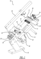
- FIG. 1 through 3 primary elements of workpiece handling system 10 are illustrated.
- the unit is supported by machine base 12 which supports frame 14.
- Frame 14 supports a pair of cylindrical rollers 16 and 18 which are supported by the frame to rotate about their longitudinal axes. Rollers 16 and 18 are positioned mutually parallel with a separation gap between them (discussed in more detail below).
- Drive motors 20 and 22 drive the rollers 16 and 18, respectively. Rollers 16 and 18 are cantilever supported such that they are driven at one of their ends with the opposite upwardly extending end unsupported.
- Slide mechanism 24 is provided to index one of the rollers to maintain either a relatively small separation gap between the rollers (during inspection) or a relatively large separation gap (following inspection).
- the separation gap dimensions are chosen such that they permit the rollers 16 and 18 to either support a representative workpiece 2 or allow the workpiece to drop through by gravity between them.
- rollers 16 and 18 are inclined at roughly a 30° angle from horizontal, presenting their ends 26 and 28 upwardly.
- Slide mechanism 24 includes actuator motor 30 and eccentric drive link 32. Upon actuation, slide 24 moves one of the rollers, roller 16 in this example, to change its separation gap distance with roller 18 while maintaining their parallel relationship.
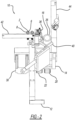
- Arm 34 is supported by frame extends beneath rollers 16 and 18 and supports eddy current inspection probe 36 which is positioned to be closely adjacent to the workpiece head 6 and flange 8 during inspection. Arm 34 also supports workpiece gate 38. Gate 38 has a sliding fence 40 which can be actuated to control the parts stream after inspection, which will be described below. Arm 34 further supports workpiece supporting plate 42, which allows workpieces 2 to roll into an inspection position. Frame 14 also supports arm 44 which can be used to support additional inspection or workpiece handling devices. For example, vision-based sensors such as laser sensors, cameras and/or other detectors can be supported by arm 44.
- vision-based sensors such as laser sensors, cameras and/or other detectors can be supported by arm 44.
- rollers 16 and 18 are oriented such that they support workpiece 2 in a position in which their separation gap distance is less than the diameter of the extending cylindrical portion of the workpiece.
- the inclined orientation of rollers 16 and 18 causes the workpieces 2 to tend to fall along their length down along the rollers under gravity but are supported at the inspection position by the interaction between the fastener head 6 and roller ends 26 and 28.
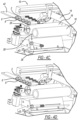
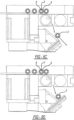
- FIG. 4A-4D and 5A-5D a representative inspection process sequence is illustrated.
- workpiece 2 is fed by gravity along plate 42 to drop into the gap between rollers 16 and 18.
- Numerous types of upstream parts handling systems such as parts sorters and other devices may be used to present workpieces 2 onto plate 42.
- a series of workpieces 2 may be lined up on plate 42 and another gating device (not illustrated) may be used to feed one part at a time at a desired rate into the roller separation gap.
- Workpieces 2 assume the position shown in Figures 4B and 5B with head 6 supported by roller ends 26 and 28.
- rollers 16 and 18 are rotated in the same clockwise or counterclockwise direction which drive workpiece 2 to also rotate.
- Eddy current probe 36 is positioned at a desired location adjacent to the workpiece head 6 and flange 8 to provide the desired crack inspection capability.
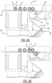
- Figures 4C, 4D , 5C and 5D illustrate the processing of the parts based on such a determination and separating them into parts streams based on their compliance with measured criteria.
- Figures 4C and 5C depict handling of a defective part. In that case workpiece 2 is dropped against workpiece gate 38 and sliding fence 40 is retracted such that the part moves toward a "defect" part stream. However, when a particular workpiece 2 meets measured criteria, sliding fence 40 is extended, allowing that workpiece to travel along sliding fence 40 into an "accept” parts stream.
- Figure 6 provides a cross-sectional view of a representative roller 16, which may also be used with an identical designed roller 18.
- the configuration illustrated is particularly suited to enable a rapid change in a roller 16 of one diameter dimension or length to a different configuration which may be suited for a specific configuration of workpiece 2.
- Roller 16 includes tube 46 having a hollow interior, a cylindrical outer surface 48 and internal tapered ends 50 and 52.
- Mandrel 54 supports roller 16 and enables it to be positioned and driven for rotation.
- Mandrel 54 forms tapered end 52 which engages with tube tapered end 50.
- Tapered plug 58 engages with tube tapered end 50.
- Threaded rod 60 meshes with internal threads 62 of mandrel 54 and passes through a clearance bore in plug 58.
- Tightening of threaded rod 60 causes the separation between tapered surfaces 56 and 58 to decrease which forces the tapered surfaces into contact, firmly mounting tube 48.
- a tube 48 of a different configuration can be readily installed onto mandrel 54 by loosening the tapered connections and replacing tube 48.
- both rollers 16 and 18 preferably have this same configuration if rapid tooling change capabilities are desired.
- rollers 16 and 18 are described as having a cylindrical outer surface and the upwardly extending ends of the rollers 26 and 28 support the workpieces 2 at their heads 6. This is according to the invention. In other configurations that are advantageous but not according to the present invention, for example, rollers 16 and 18 could have an outer surface matching a particular workpiece cross-sectional profile and indentations or features of the rollers could be configured to support a workpiece 2 at a point along the length of the rollers rather than only at the end positions as illustrated in the appended drawings.
Landscapes
- Chemical & Material Sciences (AREA)
- Chemical Kinetics & Catalysis (AREA)
- Electrochemistry (AREA)
- Physics & Mathematics (AREA)
- Health & Medical Sciences (AREA)
- Life Sciences & Earth Sciences (AREA)
- Analytical Chemistry (AREA)
- Biochemistry (AREA)
- General Health & Medical Sciences (AREA)
- General Physics & Mathematics (AREA)
- Immunology (AREA)
- Pathology (AREA)
- Investigating Or Analyzing Materials By The Use Of Magnetic Means (AREA)
Description
- This application claims priority to
United States Provisional Application No. 62/278,503, filed on January 14, 2016 - This invention relates to a workpiece inspection system and particularly to one for conducting certain types of analysis on workpieces such as cylindrical workpieces including fasteners.
- Numerous types of workpieces require 100% quality inspection during their production. A variety of production defects can occur which can lead to the workpiece being out of compliance with required specifications. Elongated cylindrical workpieces such as fasteners, pins, and dowel rods may have a cold formed fastener head or other enlarged feature. Particularly in a cold forming operation, defects such as cracks and other imperfections can result. An example would be a threaded fastener with a hex head and an integrated washer flange at the base of the driving head. Since these configuration features are critical to the performance of the workpiece in their intended application, they are frequently subject to 100% quality inspection. Various techniques for automated quality inspection are implemented today. One such technique uses an eddy current inspection system which evaluates the integrity of a formed metal component by its response to an AC induced magnetic field. These techniques are well known and widely implemented. This invention is especially adapted for eddy current inspection of cylindrical workpieces with an enlarged feature, but could be used for other types of inspection systems.
- For eddy current inspection it is necessary that the workpiece be presented and located closely adjacent to an eddy current probe. Moreover, it is necessary to rotate the workpiece such that the perimeter of the feature being inspected is presented to the eddy current probe. Numerous types of workpiece handling systems have been implemented for such inspection in the past. However, prior art systems generally have disadvantages in terms of reliability of inspection, part throughput rate capabilities, equipment and tooling cost, and excessive downtime issues. This invention is related to a workpiece handling system which provides rapid inspection, low-cost investment, reliable inspection, and which will provide little maintenance and downtime issues.
-
US 5 486 760 A discloses an apparatus for checking the outer surface of conical parts. The apparatus comprises two substantially cylindrical feeding rollers adapted to support a plurality of the parts arranged in a row. The feeding rollers define convergent geometrical axes about which the rollers rotate in the same direction and have external surfaces made of materials with a different coefficient of friction. The rotation of the feeding rollers causes the parts to rotate about their own geometrical axes and the row of parts to perform a continuous advance motion. The parts are dynamically checked by a non-contacting probe arranged substantially in correspondence with a determined cross-section of the feeding rollers. -
WO 2015/068267 A1 discloses a sorting machine in which the gap between a first roller and a second roller can be adjusted in a simple and accurate manner to a value corresponding to the size of the item to be sorted. An item size detector detects the size of the item to be sorted, and a controller transmits, on the basis of the detected item size, a command to a drive unit of a roller movement mechanism for movably and pivotally supporting the second roller, whereupon the roller movement mechanism moves the second roller in a radial direction parallel to the width direction of a device body on the basis of the command, and adjusts the gap between the first roller and the second roller to a size corresponding to the size of the item. -
US 2012/0298565 A1 discloses a machine for sorting fasteners that have a shaft with a head attached thereto from fasteners that only have a shaft. The machine has a plurality of rollers that are rotatably attached to a frame, the plurality of rollers having a gap between each other and being generally aligned parallel to each other. In addition, the plurality of rollers can be oriented at an angle relative to horizontal. The gap between each roller is dimensioned such that the shaft of a fastener can fit or fall therethrough and yet prevent the head of the fastener to fit or fall therethrough. - The workpiece handling system in accordance with the present invention includes a pair of roller elements which are inclined and separated by a small gap. Headed workpieces are directed to drop into the gap between the rollers while the ends of the rollers support the workpiece head. Rotation of the rollers causes the workpiece to also rotate, and its head is maintained in close proximity to the eddy current inspection probe. After inspection, one or more of the rollers is actuated to separate them, allowing the workpiece to drop through the gap between the rollers. A gating system is provided to direct workpieces into a "good" parts stream and a "defect" or "reject" parts stream.
-
-
Figure 1 is a pictorial view of the workpiece handling system in accordance with the present invention; -
Figure 2 is a front view of the system shown inFigure 1 ; -
Figure 3 is a right side view of the system shown inFigure 1 ; -
Figures 4A-4D are isometric views showing the system respectively feeding, scanning, rejecting, and accepting workpieces; -
Figures 5A-5D are end views showing the system respectively feeding, scanning, rejecting, and accepting workpieces; and -
Figure 6 is a cross-sectional view of a roller configuration which may be used in with the present invention. -
Workpiece handling system 10 in accordance with the present invention is adapted for inspection of generally cylindrical workpieces having a formed head or other enlargement at an end.Workpiece 2 configurations suitable for use in connection with the present invention have a radially outward projecting feature which forms an edge or flange-like surface enabling it to be supported using the machine configuration described herein. Arepresentative workpiece 2 is shown in each of the Figures.Workpiece 2 is shown in the form of a threaded bolt type fastener having threaded end 4 and an enlargedhead 6 forming a hex drive head with an integrated flange orskirt 8 which functions as a washer. As mentioned previously, the production process for producing such threaded workpieces can result in defects which tend to occur at thehead 6 and particularly at theflange 8 area. While reference is made toworkpiece 2 as described, it is to be recognized that theworkpiece handling system 10 in accordance with this invention will be applicable to other types of workpieces having an elongated cylindrical segment with an enlarged feature in the form of an elongated fastener, wherein the enlarged feature is formed by an enlarged drive head having a radially outward projecting feature which forms an edge or flange-like surface, and other types of inspection beyond eddy current type techniques. - With specific reference to
Figures 1 through 3 , primary elements ofworkpiece handling system 10 are illustrated. As shown, the unit is supported bymachine base 12 which supportsframe 14.Frame 14 supports a pair ofcylindrical rollers Rollers motors rollers Rollers Slide mechanism 24 is provided to index one of the rollers to maintain either a relatively small separation gap between the rollers (during inspection) or a relatively large separation gap (following inspection). The separation gap dimensions are chosen such that they permit therollers representative workpiece 2 or allow the workpiece to drop through by gravity between them. As illustrated,rollers ends Slide mechanism 24 includesactuator motor 30 and eccentric drive link 32. Upon actuation,slide 24 moves one of the rollers,roller 16 in this example, to change its separation gap distance withroller 18 while maintaining their parallel relationship. -
Arm 34 is supported by frame extends beneathrollers current inspection probe 36 which is positioned to be closely adjacent to theworkpiece head 6 andflange 8 during inspection.Arm 34 also supportsworkpiece gate 38.Gate 38 has asliding fence 40 which can be actuated to control the parts stream after inspection, which will be described below.Arm 34 further supportsworkpiece supporting plate 42, which allowsworkpieces 2 to roll into an inspection position.Frame 14 also supportsarm 44 which can be used to support additional inspection or workpiece handling devices. For example, vision-based sensors such as laser sensors, cameras and/or other detectors can be supported byarm 44. - As best illustrated in
Figure 3 ,rollers rollers workpieces 2 to tend to fall along their length down along the rollers under gravity but are supported at the inspection position by the interaction between thefastener head 6 and roller ends 26 and 28. - Now with reference to
Figures 4A-4D and5A-5D , a representative inspection process sequence is illustrated. InFigures 4A and5A ,workpiece 2 is fed by gravity alongplate 42 to drop into the gap betweenrollers workpieces 2 ontoplate 42. A series ofworkpieces 2 may be lined up onplate 42 and another gating device (not illustrated) may be used to feed one part at a time at a desired rate into the roller separation gap.Workpieces 2 assume the position shown inFigures 4B and5B withhead 6 supported by roller ends 26 and 28. This positioning results by gravity which tends to urge theworkpieces 2 to move down along therollers workpiece head 6 and roller ends 26 and 28.Rollers workpiece 2 to also rotate. Eddycurrent probe 36 is positioned at a desired location adjacent to theworkpiece head 6 andflange 8 to provide the desired crack inspection capability. - Based on analysis of signals from
eddy current probe 36 and potentially other inspection systems it is determined that aparticular workpiece 2 is evaluated as a "good" part or a "reject" part. After inspection, slide 24 is actuated to separaterollers workpieces 2 fall between them.Figures 4C, 4D ,5C and 5D illustrate the processing of the parts based on such a determination and separating them into parts streams based on their compliance with measured criteria.Figures 4C and5C depict handling of a defective part. In that case workpiece 2 is dropped againstworkpiece gate 38 and slidingfence 40 is retracted such that the part moves toward a "defect" part stream. However, when aparticular workpiece 2 meets measured criteria, slidingfence 40 is extended, allowing that workpiece to travel along slidingfence 40 into an "accept" parts stream. -
Figure 6 provides a cross-sectional view of arepresentative roller 16, which may also be used with an identical designedroller 18. The configuration illustrated is particularly suited to enable a rapid change in aroller 16 of one diameter dimension or length to a different configuration which may be suited for a specific configuration ofworkpiece 2.Roller 16 includes tube 46 having a hollow interior, a cylindricalouter surface 48 and internal tapered ends 50 and 52. Mandrel 54 supportsroller 16 and enables it to be positioned and driven for rotation. Mandrel 54 forms taperedend 52 which engages with tube taperedend 50.Tapered plug 58 engages with tube taperedend 50. Threadedrod 60 meshes withinternal threads 62 of mandrel 54 and passes through a clearance bore inplug 58. Tightening of threadedrod 60 causes the separation between taperedsurfaces tube 48. Atube 48 of a different configuration can be readily installed onto mandrel 54 by loosening the tapered connections and replacingtube 48. As mentioned previously, bothrollers - In this description,
rollers rollers workpieces 2 at theirheads 6. This is according to the invention. In other configurations that are advantageous but not according to the present invention, for example,rollers workpiece 2 at a point along the length of the rollers rather than only at the end positions as illustrated in the appended drawings.
Claims (9)
- A workpiece handling system (10) for inspection of a workpiece (2) of a type having an elongated cylindrical segment with an enlarged feature (6) in the form of an elongated fastener, wherein the enlarged feature (6) is formed by an enlarged drive head having a radially outward projecting feature which forms an edge or flange-like surface, comprising- a pair of rollers (16,18) inclined with respect to horizontal, each of the rollers (16,18) having a cylindrical outer surface (48), the pair of rollers (16,18) oriented with parallel axes and rotatable, each of the rollers (16,18) having an upwardly presented end (26,28), wherein the roller ends (26,28) support the enlarged feature (6) of the workpiece (2),- a drive arrangement for rotating the pair of rollers (16,18) in a rotational direction about their axes,- a slide mechanism (24) enabling the rollers (16,18) to be set at a first separation gap to a second separation gap larger than the first separation gap,- a workpiece transfer mechanism for loading the workpiece (2) onto the pair of rollers (16,18) such that the cylindrical segment is in contact with the roller cylindrical surfaces (48) of both of the rollers (16,18) and the rollers (16,18) support the enlarged feature (6) of the workpiece (2), whereby rotation of the rollers (16,18) while the rollers (16,18) are set at the first separation gap causes the workpiece (2) to rotate,- a sensor probe (36) positioned in close proximity to the enlarged feature (6) of the workpiece as the workpiece (2) is rotated by the rollers (16,18),
whereby the sensor probe (36) is an eddy current sensor probe, and- a workpiece receiving system for handling the workpiece (2) when the rollers (16,18) are set to the second separation gap by the slide mechanism (24), allowing the workpiece (2) to fall under gravity between the rollers (16,18) onto the workpiece receiving system. - A workpiece handling system (10) in accordance with claim 1, characterized in that the pair of rollers (16,18) is inclined such that longitudinal axes of each of the rollers (16,18) form an angle of about 30 degrees from horizontal.
- A workpiece handling system (10) in accordance with claim 1, characterized in that the workpiece receiving system further comprises a gate (38) for separating the workpiece (2) between a group meeting an inspection criterion and a group not meeting the inspection criterion.
- A workpiece handling system (10) in accordance with claim 1, characterized in that the workpiece transfer mechanism includes an inclined plate (42) which receives and supports the workpiece (2) such that the workpiece (2) rolls along the plate (42) onto the rollers (16,18) and into the first separation gap between the rollers (16,18).
- A workpiece handling system (10) in accordance with claim 1, characterized in that each roller (16,18) has an outer tube (46) forming an interior hollow cavity, the roller (16,18) further having internal first and second tapered surfaces (56) at the ends of the roller (16,18), a mandrel (54) forming a first tapered surface adapted to conform with the first roller tapered surface (56), a plug forming a tapered surface (58) adapted to conform with the second roller tapered surface, a threaded rod (60) extending between the plug and the mandrel (54) enabling the mandrel (54) and plug to be tightened to drive the mandrel (54) tapered surface and the plug tapered surface (58) into engagement with the roller first and second tapered surfaces (56).
- A workpiece handling system (10) in accordance with claim 1, characterized in that each of the rollers (16,18) is cantilever supported, wherein one roller end is mounted to the drive arrangement and the opposite upwardly presented end (26,28) is unsupported.
- A workpiece handling system (10) in accordance with claim 3, characterized in that the pair of rollers (16,48) is inclined such that longitudinal axes of each of the rollers (16,18) form an angle of about 30 degrees from horizontal.
- A workpiece handling system (10) in accordance with claim 3, characterized in that the workpiece transfer mechanism includes an inclined plate (42) which receives and supports the workpiece (2) such that the workpiece (2) rolls along the plate (42) onto the rollers (16,18) and into the first separation gap between the rollers (16,18).
- A workpiece handling system (10) in accordance with claim 3, characterized in that each roller (16,18) has an outer tube (46) forming an interior hollow cavity, the roller (16,18) further having internal first and second tapered surfaces (56) at the ends of the roller, a mandrel (54) forming a first tapered surface adapted to conform with the first roller tapered surface (56), a plug forming a tapered surface (58) adapted to conform with the second roller tapered surface, a threaded rod (60) extending between the plug and the mandrel (54) enabling the mandrel (54) and plug to be tightened to drive the mandrel tapered surface and the plug tapered surface (58) into engagement with the roller first and second tapered surfaces (56), or wherein each of the rollers (16,18) is cantilever supported, wherein one roller end is mounted to the drive arrangement and the opposite upwardly presented end (26,28) is unsupported.
Applications Claiming Priority (2)
| Application Number | Priority Date | Filing Date | Title |
|---|---|---|---|
| US201662278503P | 2016-01-14 | 2016-01-14 | |
| PCT/US2017/013152 WO2017123727A1 (en) | 2016-01-14 | 2017-01-12 | Eddy current system for workpiece inspection |
Publications (3)
| Publication Number | Publication Date |
|---|---|
| EP3402612A1 EP3402612A1 (en) | 2018-11-21 |
| EP3402612A4 EP3402612A4 (en) | 2019-09-18 |
| EP3402612B1 true EP3402612B1 (en) | 2023-09-13 |
Family
ID=59311429
Family Applications (1)
| Application Number | Title | Priority Date | Filing Date |
|---|---|---|---|
| EP17738911.1A Active EP3402612B1 (en) | 2016-01-14 | 2017-01-12 | Eddy current system for workpiece inspection |
Country Status (4)
| Country | Link |
|---|---|
| US (1) | US10724993B2 (en) |
| EP (1) | EP3402612B1 (en) |
| FI (1) | FI3402612T3 (en) |
| WO (1) | WO2017123727A1 (en) |
Families Citing this family (4)
| Publication number | Priority date | Publication date | Assignee | Title |
|---|---|---|---|---|
| CN109719048B (en) * | 2019-03-07 | 2024-02-13 | 重庆市诚润机械有限公司 | Automatic intelligent unloading system that detects a flaw of silver bright steel stick |
| CN113798140B (en) * | 2021-09-17 | 2023-01-24 | 北京闼闼同创工贸有限公司 | Automatic production line |
| CN113600507B (en) * | 2021-10-09 | 2022-03-25 | 常州日晖电池有限公司 | Button cell detects screening plant |
| CN115007482B (en) * | 2022-03-02 | 2024-05-10 | 苏州德斯森电子有限公司 | Piston pin detection machine |
Family Cites Families (15)
| Publication number | Priority date | Publication date | Assignee | Title |
|---|---|---|---|---|
| US3886793A (en) * | 1974-01-09 | 1975-06-03 | Us Navy | Projectile body testing machine |
| US4801020A (en) | 1987-04-21 | 1989-01-31 | Rogne Conrad O | Apparatus and method for detecting defects in a spherical object |
| IT1252413B (en) * | 1991-07-04 | 1995-06-14 | Marposs Spa | EQUIPMENT AND METHOD FOR THE CONTROL OF MECHANICAL PIECES WITH ROTATION SYMMETRY |
| US5823356A (en) * | 1996-04-25 | 1998-10-20 | Ajax Metal Processing, Inc. | Apparatus and method for insepcting threaded members |
| US20050174567A1 (en) | 2004-02-09 | 2005-08-11 | Mectron Engineering Company | Crack detection system |
| US20060236792A1 (en) * | 2005-04-22 | 2006-10-26 | Mectron Engineering Company | Workpiece inspection system |
| JP5007706B2 (en) * | 2008-06-30 | 2012-08-22 | 信越半導体株式会社 | Work cutting method |
| JP2010115741A (en) * | 2008-11-12 | 2010-05-27 | Toshiba Mach Co Ltd | Cutting method of high hardness material and cutting machine |
| KR101183537B1 (en) | 2011-03-28 | 2012-09-20 | 주식회사 아세아볼트 | Apparatus for sorting screw having a function of inspection badness using image process |
| US8875902B2 (en) * | 2011-05-25 | 2014-11-04 | Toyota Motor Engineering & Manufacturing North America, Inc. | Fastener sorting device and processing thereof |
| DE102012112121B4 (en) * | 2012-12-11 | 2023-02-09 | Baker Hughes Digital Solutions Gmbh | Method and device for non-destructive testing of a rotationally symmetrical workpiece which has sections of different diameters |
| US9366579B2 (en) * | 2012-12-21 | 2016-06-14 | John Bean Technologies Corporation | Thermal process control |
| WO2014137408A1 (en) | 2013-03-07 | 2014-09-12 | Mectron Engineering Company, Inc. | Inspection system for threaded parts |
| CN105188964B (en) * | 2013-11-08 | 2017-10-03 | Ykk株式会社 | sorting machine |
| DE102015014490A1 (en) * | 2015-11-10 | 2017-05-11 | GM Global Technology Operations LLC (n. d. Ges. d. Staates Delaware) | Process for processing a sheet metal workpiece |
-
2017
- 2017-01-12 WO PCT/US2017/013152 patent/WO2017123727A1/en not_active Ceased
- 2017-01-12 US US16/070,054 patent/US10724993B2/en active Active
- 2017-01-12 EP EP17738911.1A patent/EP3402612B1/en active Active
- 2017-01-12 FI FIEP17738911.1T patent/FI3402612T3/en active
Also Published As
| Publication number | Publication date |
|---|---|
| EP3402612A4 (en) | 2019-09-18 |
| FI3402612T3 (en) | 2023-12-12 |
| EP3402612A1 (en) | 2018-11-21 |
| WO2017123727A1 (en) | 2017-07-20 |
| US10724993B2 (en) | 2020-07-28 |
| US20190033259A1 (en) | 2019-01-31 |
Similar Documents
| Publication | Publication Date | Title |
|---|---|---|
| EP3402612B1 (en) | Eddy current system for workpiece inspection | |
| US5823356A (en) | Apparatus and method for insepcting threaded members | |
| EP1715335A1 (en) | Workpiece inspection system | |
| KR101767964B1 (en) | Rotary falling type bolt sorting apparatus including bolt side vision inspector | |
| KR101980860B1 (en) | A spring pin separating apparatus | |
| CN107626602A (en) | Bearing automatic measurement sorting equipment based on micro-displacement sensor | |
| KR20220056094A (en) | Pipe bolt inspection device with position alignment | |
| US7245759B2 (en) | Method of inspecting threaded fasteners and a system therefor | |
| JP4621937B2 (en) | Work bending inspection system | |
| CN115055388B (en) | Automatic product detection machine | |
| CN105188964B (en) | sorting machine | |
| CN204731168U (en) | A kind of sheet plug of turnable detects machine | |
| CN110153026A (en) | A kind of ball size detection sorter | |
| JP2020083626A (en) | Component conveyance inspection machine | |
| CN118455098A (en) | Full-automatic size and appearance inspection production device and method for bolts | |
| CN117259233A (en) | A fruit sorting system and sorting method | |
| JPH11223504A (en) | Inspection device for axial workpiece | |
| CN114453265A (en) | Conveying system for intelligent production of electronic components | |
| JP3180893U (en) | Scaffolding bolt automatic inspection device and automatic sorter equipped with the inspection device | |
| JPS6329207A (en) | Inspection instrument for appearance of headless rod type component | |
| CN222165941U (en) | Detection device | |
| KR102687326B1 (en) | Nut Roll Tapping Machine | |
| JP6539229B2 (en) | Shaft processing unit | |
| KR102687324B1 (en) | Nut Roll Tapping Machine | |
| JPH03195914A (en) | Inspecting apparatus for thread of bolt |
Legal Events
| Date | Code | Title | Description |
|---|---|---|---|
| STAA | Information on the status of an ep patent application or granted ep patent |
Free format text: STATUS: THE INTERNATIONAL PUBLICATION HAS BEEN MADE |
|
| PUAI | Public reference made under article 153(3) epc to a published international application that has entered the european phase |
Free format text: ORIGINAL CODE: 0009012 |
|
| STAA | Information on the status of an ep patent application or granted ep patent |
Free format text: STATUS: REQUEST FOR EXAMINATION WAS MADE |
|
| 17P | Request for examination filed |
Effective date: 20180809 |
|
| AK | Designated contracting states |
Kind code of ref document: A1 Designated state(s): AL AT BE BG CH CY CZ DE DK EE ES FI FR GB GR HR HU IE IS IT LI LT LU LV MC MK MT NL NO PL PT RO RS SE SI SK SM TR |
|
| AX | Request for extension of the european patent |
Extension state: BA ME |
|
| DAV | Request for validation of the european patent (deleted) | ||
| DAX | Request for extension of the european patent (deleted) | ||
| A4 | Supplementary search report drawn up and despatched |
Effective date: 20190816 |
|
| RIC1 | Information provided on ipc code assigned before grant |
Ipc: G01N 27/24 20060101ALI20190809BHEP Ipc: G01N 27/20 20060101ALI20190809BHEP Ipc: G01N 27/90 20060101ALI20190809BHEP Ipc: G01N 27/82 20060101ALI20190809BHEP Ipc: G01N 27/87 20060101ALI20190809BHEP Ipc: G01B 21/00 20060101ALI20190809BHEP Ipc: B07C 5/34 20060101AFI20190809BHEP |
|
| STAA | Information on the status of an ep patent application or granted ep patent |
Free format text: STATUS: EXAMINATION IS IN PROGRESS |
|
| 17Q | First examination report despatched |
Effective date: 20210719 |
|
| GRAP | Despatch of communication of intention to grant a patent |
Free format text: ORIGINAL CODE: EPIDOSNIGR1 |
|
| STAA | Information on the status of an ep patent application or granted ep patent |
Free format text: STATUS: GRANT OF PATENT IS INTENDED |
|
| INTG | Intention to grant announced |
Effective date: 20230425 |
|
| GRAS | Grant fee paid |
Free format text: ORIGINAL CODE: EPIDOSNIGR3 |
|
| GRAA | (expected) grant |
Free format text: ORIGINAL CODE: 0009210 |
|
| STAA | Information on the status of an ep patent application or granted ep patent |
Free format text: STATUS: THE PATENT HAS BEEN GRANTED |
|
| AK | Designated contracting states |
Kind code of ref document: B1 Designated state(s): AL AT BE BG CH CY CZ DE DK EE ES FI FR GB GR HR HU IE IS IT LI LT LU LV MC MK MT NL NO PL PT RO RS SE SI SK SM TR |
|
| REG | Reference to a national code |
Ref country code: GB Ref legal event code: FG4D |
|
| REG | Reference to a national code |
Ref country code: CH Ref legal event code: EP |
|
| REG | Reference to a national code |
Ref country code: DE Ref legal event code: R096 Ref document number: 602017074145 Country of ref document: DE |
|
| P01 | Opt-out of the competence of the unified patent court (upc) registered |
Effective date: 20230904 |
|
| REG | Reference to a national code |
Ref country code: IE Ref legal event code: FG4D |
|
| REG | Reference to a national code |
Ref country code: SE Ref legal event code: TRGR |
|
| REG | Reference to a national code |
Ref country code: FI Ref legal event code: FGE |
|
| REG | Reference to a national code |
Ref country code: LT Ref legal event code: MG9D |
|
| REG | Reference to a national code |
Ref country code: NL Ref legal event code: MP Effective date: 20230913 |
|
| PG25 | Lapsed in a contracting state [announced via postgrant information from national office to epo] |
Ref country code: GR Free format text: LAPSE BECAUSE OF FAILURE TO SUBMIT A TRANSLATION OF THE DESCRIPTION OR TO PAY THE FEE WITHIN THE PRESCRIBED TIME-LIMIT Effective date: 20231214 |
|
| PG25 | Lapsed in a contracting state [announced via postgrant information from national office to epo] |
Ref country code: RS Free format text: LAPSE BECAUSE OF FAILURE TO SUBMIT A TRANSLATION OF THE DESCRIPTION OR TO PAY THE FEE WITHIN THE PRESCRIBED TIME-LIMIT Effective date: 20230913 Ref country code: NO Free format text: LAPSE BECAUSE OF FAILURE TO SUBMIT A TRANSLATION OF THE DESCRIPTION OR TO PAY THE FEE WITHIN THE PRESCRIBED TIME-LIMIT Effective date: 20231213 Ref country code: LV Free format text: LAPSE BECAUSE OF FAILURE TO SUBMIT A TRANSLATION OF THE DESCRIPTION OR TO PAY THE FEE WITHIN THE PRESCRIBED TIME-LIMIT Effective date: 20230913 Ref country code: LT Free format text: LAPSE BECAUSE OF FAILURE TO SUBMIT A TRANSLATION OF THE DESCRIPTION OR TO PAY THE FEE WITHIN THE PRESCRIBED TIME-LIMIT Effective date: 20230913 Ref country code: HR Free format text: LAPSE BECAUSE OF FAILURE TO SUBMIT A TRANSLATION OF THE DESCRIPTION OR TO PAY THE FEE WITHIN THE PRESCRIBED TIME-LIMIT Effective date: 20230913 Ref country code: GR Free format text: LAPSE BECAUSE OF FAILURE TO SUBMIT A TRANSLATION OF THE DESCRIPTION OR TO PAY THE FEE WITHIN THE PRESCRIBED TIME-LIMIT Effective date: 20231214 |
|
| REG | Reference to a national code |
Ref country code: AT Ref legal event code: MK05 Ref document number: 1610739 Country of ref document: AT Kind code of ref document: T Effective date: 20230913 |
|
| PG25 | Lapsed in a contracting state [announced via postgrant information from national office to epo] |
Ref country code: NL Free format text: LAPSE BECAUSE OF FAILURE TO SUBMIT A TRANSLATION OF THE DESCRIPTION OR TO PAY THE FEE WITHIN THE PRESCRIBED TIME-LIMIT Effective date: 20230913 |
|
| PG25 | Lapsed in a contracting state [announced via postgrant information from national office to epo] |
Ref country code: IS Free format text: LAPSE BECAUSE OF FAILURE TO SUBMIT A TRANSLATION OF THE DESCRIPTION OR TO PAY THE FEE WITHIN THE PRESCRIBED TIME-LIMIT Effective date: 20240113 |
|
| PG25 | Lapsed in a contracting state [announced via postgrant information from national office to epo] |
Ref country code: AT Free format text: LAPSE BECAUSE OF FAILURE TO SUBMIT A TRANSLATION OF THE DESCRIPTION OR TO PAY THE FEE WITHIN THE PRESCRIBED TIME-LIMIT Effective date: 20230913 |
|
| PG25 | Lapsed in a contracting state [announced via postgrant information from national office to epo] |
Ref country code: ES Free format text: LAPSE BECAUSE OF FAILURE TO SUBMIT A TRANSLATION OF THE DESCRIPTION OR TO PAY THE FEE WITHIN THE PRESCRIBED TIME-LIMIT Effective date: 20230913 |
|
| PG25 | Lapsed in a contracting state [announced via postgrant information from national office to epo] |
Ref country code: SM Free format text: LAPSE BECAUSE OF FAILURE TO SUBMIT A TRANSLATION OF THE DESCRIPTION OR TO PAY THE FEE WITHIN THE PRESCRIBED TIME-LIMIT Effective date: 20230913 Ref country code: RO Free format text: LAPSE BECAUSE OF FAILURE TO SUBMIT A TRANSLATION OF THE DESCRIPTION OR TO PAY THE FEE WITHIN THE PRESCRIBED TIME-LIMIT Effective date: 20230913 Ref country code: IS Free format text: LAPSE BECAUSE OF FAILURE TO SUBMIT A TRANSLATION OF THE DESCRIPTION OR TO PAY THE FEE WITHIN THE PRESCRIBED TIME-LIMIT Effective date: 20240113 Ref country code: ES Free format text: LAPSE BECAUSE OF FAILURE TO SUBMIT A TRANSLATION OF THE DESCRIPTION OR TO PAY THE FEE WITHIN THE PRESCRIBED TIME-LIMIT Effective date: 20230913 Ref country code: EE Free format text: LAPSE BECAUSE OF FAILURE TO SUBMIT A TRANSLATION OF THE DESCRIPTION OR TO PAY THE FEE WITHIN THE PRESCRIBED TIME-LIMIT Effective date: 20230913 Ref country code: CZ Free format text: LAPSE BECAUSE OF FAILURE TO SUBMIT A TRANSLATION OF THE DESCRIPTION OR TO PAY THE FEE WITHIN THE PRESCRIBED TIME-LIMIT Effective date: 20230913 Ref country code: AT Free format text: LAPSE BECAUSE OF FAILURE TO SUBMIT A TRANSLATION OF THE DESCRIPTION OR TO PAY THE FEE WITHIN THE PRESCRIBED TIME-LIMIT Effective date: 20230913 Ref country code: PT Free format text: LAPSE BECAUSE OF FAILURE TO SUBMIT A TRANSLATION OF THE DESCRIPTION OR TO PAY THE FEE WITHIN THE PRESCRIBED TIME-LIMIT Effective date: 20240115 Ref country code: SK Free format text: LAPSE BECAUSE OF FAILURE TO SUBMIT A TRANSLATION OF THE DESCRIPTION OR TO PAY THE FEE WITHIN THE PRESCRIBED TIME-LIMIT Effective date: 20230913 |
|
| PG25 | Lapsed in a contracting state [announced via postgrant information from national office to epo] |
Ref country code: PL Free format text: LAPSE BECAUSE OF FAILURE TO SUBMIT A TRANSLATION OF THE DESCRIPTION OR TO PAY THE FEE WITHIN THE PRESCRIBED TIME-LIMIT Effective date: 20230913 |
|
| REG | Reference to a national code |
Ref country code: DE Ref legal event code: R097 Ref document number: 602017074145 Country of ref document: DE |
|
| PG25 | Lapsed in a contracting state [announced via postgrant information from national office to epo] |
Ref country code: DK Free format text: LAPSE BECAUSE OF FAILURE TO SUBMIT A TRANSLATION OF THE DESCRIPTION OR TO PAY THE FEE WITHIN THE PRESCRIBED TIME-LIMIT Effective date: 20230913 |
|
| PLBE | No opposition filed within time limit |
Free format text: ORIGINAL CODE: 0009261 |
|
| STAA | Information on the status of an ep patent application or granted ep patent |
Free format text: STATUS: NO OPPOSITION FILED WITHIN TIME LIMIT |
|
| PG25 | Lapsed in a contracting state [announced via postgrant information from national office to epo] |
Ref country code: DK Free format text: LAPSE BECAUSE OF FAILURE TO SUBMIT A TRANSLATION OF THE DESCRIPTION OR TO PAY THE FEE WITHIN THE PRESCRIBED TIME-LIMIT Effective date: 20230913 |
|
| 26N | No opposition filed |
Effective date: 20240614 |
|
| PG25 | Lapsed in a contracting state [announced via postgrant information from national office to epo] |
Ref country code: MC Free format text: LAPSE BECAUSE OF FAILURE TO SUBMIT A TRANSLATION OF THE DESCRIPTION OR TO PAY THE FEE WITHIN THE PRESCRIBED TIME-LIMIT Effective date: 20230913 |
|
| PG25 | Lapsed in a contracting state [announced via postgrant information from national office to epo] |
Ref country code: MC Free format text: LAPSE BECAUSE OF FAILURE TO SUBMIT A TRANSLATION OF THE DESCRIPTION OR TO PAY THE FEE WITHIN THE PRESCRIBED TIME-LIMIT Effective date: 20230913 |
|
| REG | Reference to a national code |
Ref country code: CH Ref legal event code: PL |
|
| PG25 | Lapsed in a contracting state [announced via postgrant information from national office to epo] |
Ref country code: LU Free format text: LAPSE BECAUSE OF NON-PAYMENT OF DUE FEES Effective date: 20240112 |
|
| PG25 | Lapsed in a contracting state [announced via postgrant information from national office to epo] |
Ref country code: LU Free format text: LAPSE BECAUSE OF NON-PAYMENT OF DUE FEES Effective date: 20240112 |
|
| PG25 | Lapsed in a contracting state [announced via postgrant information from national office to epo] |
Ref country code: BE Free format text: LAPSE BECAUSE OF NON-PAYMENT OF DUE FEES Effective date: 20240131 |
|
| PG25 | Lapsed in a contracting state [announced via postgrant information from national office to epo] |
Ref country code: CH Free format text: LAPSE BECAUSE OF NON-PAYMENT OF DUE FEES Effective date: 20240131 |
|
| PG25 | Lapsed in a contracting state [announced via postgrant information from national office to epo] |
Ref country code: SI Free format text: LAPSE BECAUSE OF FAILURE TO SUBMIT A TRANSLATION OF THE DESCRIPTION OR TO PAY THE FEE WITHIN THE PRESCRIBED TIME-LIMIT Effective date: 20230913 |
|
| PG25 | Lapsed in a contracting state [announced via postgrant information from national office to epo] |
Ref country code: SI Free format text: LAPSE BECAUSE OF FAILURE TO SUBMIT A TRANSLATION OF THE DESCRIPTION OR TO PAY THE FEE WITHIN THE PRESCRIBED TIME-LIMIT Effective date: 20230913 Ref country code: CH Free format text: LAPSE BECAUSE OF NON-PAYMENT OF DUE FEES Effective date: 20240131 Ref country code: BE Free format text: LAPSE BECAUSE OF NON-PAYMENT OF DUE FEES Effective date: 20240131 |
|
| REG | Reference to a national code |
Ref country code: BE Ref legal event code: MM Effective date: 20240131 |
|
| PG25 | Lapsed in a contracting state [announced via postgrant information from national office to epo] |
Ref country code: BG Free format text: LAPSE BECAUSE OF FAILURE TO SUBMIT A TRANSLATION OF THE DESCRIPTION OR TO PAY THE FEE WITHIN THE PRESCRIBED TIME-LIMIT Effective date: 20230913 |
|
| PG25 | Lapsed in a contracting state [announced via postgrant information from national office to epo] |
Ref country code: BG Free format text: LAPSE BECAUSE OF FAILURE TO SUBMIT A TRANSLATION OF THE DESCRIPTION OR TO PAY THE FEE WITHIN THE PRESCRIBED TIME-LIMIT Effective date: 20230913 |
|
| PG25 | Lapsed in a contracting state [announced via postgrant information from national office to epo] |
Ref country code: IE Free format text: LAPSE BECAUSE OF NON-PAYMENT OF DUE FEES Effective date: 20240112 |
|
| PG25 | Lapsed in a contracting state [announced via postgrant information from national office to epo] |
Ref country code: IE Free format text: LAPSE BECAUSE OF NON-PAYMENT OF DUE FEES Effective date: 20240112 |
|
| PG25 | Lapsed in a contracting state [announced via postgrant information from national office to epo] |
Ref country code: CY Free format text: LAPSE BECAUSE OF FAILURE TO SUBMIT A TRANSLATION OF THE DESCRIPTION OR TO PAY THE FEE WITHIN THE PRESCRIBED TIME-LIMIT; INVALID AB INITIO Effective date: 20170112 |
|
| PG25 | Lapsed in a contracting state [announced via postgrant information from national office to epo] |
Ref country code: HU Free format text: LAPSE BECAUSE OF FAILURE TO SUBMIT A TRANSLATION OF THE DESCRIPTION OR TO PAY THE FEE WITHIN THE PRESCRIBED TIME-LIMIT; INVALID AB INITIO Effective date: 20170112 |
|
| PG25 | Lapsed in a contracting state [announced via postgrant information from national office to epo] |
Ref country code: TR Free format text: LAPSE BECAUSE OF FAILURE TO SUBMIT A TRANSLATION OF THE DESCRIPTION OR TO PAY THE FEE WITHIN THE PRESCRIBED TIME-LIMIT Effective date: 20230913 |
|
| PGFP | Annual fee paid to national office [announced via postgrant information from national office to epo] |
Ref country code: SE Payment date: 20260127 Year of fee payment: 10 |
|
| PGFP | Annual fee paid to national office [announced via postgrant information from national office to epo] |
Ref country code: GB Payment date: 20260127 Year of fee payment: 10 |
|
| PGFP | Annual fee paid to national office [announced via postgrant information from national office to epo] |
Ref country code: DE Payment date: 20260128 Year of fee payment: 10 |
|
| PGFP | Annual fee paid to national office [announced via postgrant information from national office to epo] |
Ref country code: FI Payment date: 20260126 Year of fee payment: 10 Ref country code: IT Payment date: 20260121 Year of fee payment: 10 |
|
| PGFP | Annual fee paid to national office [announced via postgrant information from national office to epo] |
Ref country code: FR Payment date: 20260126 Year of fee payment: 10 |