EP3402610B1 - Stand-and-spray foam delivery method and device thereof - Google Patents
Stand-and-spray foam delivery method and device thereof Download PDFInfo
- Publication number
- EP3402610B1 EP3402610B1 EP17738817.0A EP17738817A EP3402610B1 EP 3402610 B1 EP3402610 B1 EP 3402610B1 EP 17738817 A EP17738817 A EP 17738817A EP 3402610 B1 EP3402610 B1 EP 3402610B1
- Authority
- EP
- European Patent Office
- Prior art keywords
- actuator
- valve
- foam
- stem
- opening
- Prior art date
- Legal status (The legal status is an assumption and is not a legal conclusion. Google has not performed a legal analysis and makes no representation as to the accuracy of the status listed.)
- Active
Links
Images

Classifications
-
- A—HUMAN NECESSITIES
- A63—SPORTS; GAMES; AMUSEMENTS
- A63C—SKATES; SKIS; ROLLER SKATES; DESIGN OR LAYOUT OF COURTS, RINKS OR THE LIKE
- A63C19/00—Design or layout of playing courts, rinks, bowling greens or areas for water-skiing; Covers therefor
- A63C19/06—Apparatus for setting-out or dividing courts
- A63C19/065—Line markings, e.g. tapes; Methods therefor
-
- B—PERFORMING OPERATIONS; TRANSPORTING
- B05—SPRAYING OR ATOMISING IN GENERAL; APPLYING FLUENT MATERIALS TO SURFACES, IN GENERAL
- B05D—PROCESSES FOR APPLYING FLUENT MATERIALS TO SURFACES, IN GENERAL
- B05D1/00—Processes for applying liquids or other fluent materials
- B05D1/02—Processes for applying liquids or other fluent materials performed by spraying
-
- B—PERFORMING OPERATIONS; TRANSPORTING
- B65—CONVEYING; PACKING; STORING; HANDLING THIN OR FILAMENTARY MATERIAL
- B65D—CONTAINERS FOR STORAGE OR TRANSPORT OF ARTICLES OR MATERIALS, e.g. BAGS, BARRELS, BOTTLES, BOXES, CANS, CARTONS, CRATES, DRUMS, JARS, TANKS, HOPPERS, FORWARDING CONTAINERS; ACCESSORIES, CLOSURES, OR FITTINGS THEREFOR; PACKAGING ELEMENTS; PACKAGES
- B65D83/00—Containers or packages with special means for dispensing contents
- B65D83/14—Containers for dispensing liquid or semi-liquid contents by internal gaseous pressure, i.e. aerosol containers comprising propellant
- B65D83/16—Actuating means
- B65D83/20—Actuator caps
- B65D83/206—Actuator caps comprising cantilevered actuating elements, e.g. levers pivoting about living hinges
-
- C—CHEMISTRY; METALLURGY
- C09—DYES; PAINTS; POLISHES; NATURAL RESINS; ADHESIVES; COMPOSITIONS NOT OTHERWISE PROVIDED FOR; APPLICATIONS OF MATERIALS NOT OTHERWISE PROVIDED FOR
- C09D—COATING COMPOSITIONS, e.g. PAINTS, VARNISHES OR LACQUERS; FILLING PASTES; CHEMICAL PAINT OR INK REMOVERS; INKS; CORRECTING FLUIDS; WOODSTAINS; PASTES OR SOLIDS FOR COLOURING OR PRINTING; USE OF MATERIALS THEREFOR
- C09D5/00—Coating compositions, e.g. paints, varnishes or lacquers, characterised by their physical nature or the effects produced; Filling pastes
- C09D5/02—Emulsion paints including aerosols
-
- C—CHEMISTRY; METALLURGY
- C09—DYES; PAINTS; POLISHES; NATURAL RESINS; ADHESIVES; COMPOSITIONS NOT OTHERWISE PROVIDED FOR; APPLICATIONS OF MATERIALS NOT OTHERWISE PROVIDED FOR
- C09D—COATING COMPOSITIONS, e.g. PAINTS, VARNISHES OR LACQUERS; FILLING PASTES; CHEMICAL PAINT OR INK REMOVERS; INKS; CORRECTING FLUIDS; WOODSTAINS; PASTES OR SOLIDS FOR COLOURING OR PRINTING; USE OF MATERIALS THEREFOR
- C09D5/00—Coating compositions, e.g. paints, varnishes or lacquers, characterised by their physical nature or the effects produced; Filling pastes
- C09D5/44—Coating compositions, e.g. paints, varnishes or lacquers, characterised by their physical nature or the effects produced; Filling pastes for electrophoretic applications
- C09D5/4419—Coating compositions, e.g. paints, varnishes or lacquers, characterised by their physical nature or the effects produced; Filling pastes for electrophoretic applications with polymers obtained otherwise than by polymerisation reactions only involving carbon-to-carbon unsaturated bonds
Definitions
- the invention relates to foam sprays and devices for the application of such a spray, particularly those that are used to make temporary markings on hard surfaces such as the ground, floor or a playing field.
- Vanishing sprays and vanishing foams are known substances that are frequently used on athletic fields and other surfaces in order to provide a temporary visual marker.
- the spray is applied from an aerosol can, which is typically small enough to comfortably fit in the user's hand and attach to a holster on user's belt.
- the foam In order for the foam to be useful, it must create a neat and well defined line that is readily visible and that, depending on the style of actuator, measures on average 1 to 4 inches in width.
- the foam is created from a liquid mixture that is roughly 80% water, between 4% and 18% propellant (such as butane gas), roughly 1% to 2% surfactant, with the remainder generally comprising preservatives.
- propellant such as butane gas
- the liquid mixture agitates and boils at atmospheric pressure it expands into foam that is typically visible for one to five minutes.
- the mixture begins to agitate and boil, thereby beginning the transformation from liquid to foam, as it passes through the actuator, completing the transition from liquid to foam in the air shortly after leaving the can and generally prior to contacting the surface.
- the conventional actuator has an actuator orifice that is approximately between 3 and 6 millimeters wide, that is curved or angled, and that is bent or partially obstructed so as to create agitation within the actuator.
- a user must hold the can very near to the ground, typically between two and twelve inches above the surface, to apply the spray and create a useful line on the surface. If the user holds the can any further from the surface the foam results in a wide pattern, ranging on average between at least six inches in width and sometimes measuring over a foot in width on the ground, forming something that resembles a splattering pattern, that is unusable as a reference line, with an inconsistent and sparse concentration of foam, as opposed to the neat and well-formed foam line of highly visible foam that is practical to use.
- An example of such an ill-formed line is illustrated in FIG. 7 .
- EP2457622 provides a foaming composition, preferably included in a spray dispensing canister, which is applicable to different surface textures, such as grass, turf, concrete, clay, granite tiles, ceramics, wooden floors and any other surface where it may be required to make temporary marks, regardless of weather conditions such as intense sunlight, heat, cold, rain, etc.
- US2004/221766 provides a foaming aqueous composition to temporarily mark and delimit regulation distances on courts and fields of sports, suitable for use in sport competitions in which it is required to momentarily delimit distances by means of a quick application.
- US2009/032618 and US6161735 show conventional can and delivery systems.
- the former relates to a sprayer comprising a motorized liquid spray head or spray pump assembly and includes an operating mechanism adapted to provide the user a push button actuated, automatic power spray for any variety of generally liquid or fluid materials, and the latter relates to a dispensing structure for aerosol containers designed for satisfactory dispensing of aerosol while controlling the discharge rate of the aerosol contained within.
- the devices disclosed in both of the above documents have a distinct bend in the nozzle/delivery opening.
- the delivery tube that extends downwards into the reservoir experiences something near to a 90-degree bend as the tube exits the reservoir and makes its way to the nozzle.
- the mixture will first hit this bend within the delivery device which starts to activate the mixture, meaning that the mixture starts to transition from a liquid to a foam within the delivery device and/or as it exits the device.
- US2009/032618 discloses the use of different known nozzles that create varying spray patterns but none of those enable the overall device to deliver the solution without first introducing agitation, which, at a minimum, would occur before the solution reaches the nozzle.
- a relatively complex "actuator assist" disclosed in this application also does not alleviate the prior agitation.
- the invention is a device as claimed in claims 1 to 4 for delivering a vanishing foam formula.
- the applicator device allows a user to stand upright and spray a neat and well-formed line of foam having little or no splattering or overspray on a surface, the line measuring on average between one and two inches in width and being easy to see from a standing position.
- the applicator device combines a conventional foam-dispensing aerosol can and conventional foam-dispensing valve with an actuator that has a comparatively long and narrow actuator orifice having a cylindrical shape with a round opening and straight sidewalls.
- the design of the actuator and composition of the formula allow for a narrow spray of the formula that experiences little to no agitation as it leaves the applicator device, thus allowing the agitation and, consequently, the foaming to occur when the spray contacts a surface, such as the ground or the surface of a playing field.
- the design of the actuator requires that the aerosol can be held in an inverted position to apply the foam to a lower surface.
- the user is able to stand upright and spray a neat foam line having little to no splattering or overspray and maintaining a usable width and density on the surface.
- the vanishing foam formula preferably contains a higher level of surfactant than is found in the conventional formulas so as to provide for sufficient foaming when the formula hits the ground.
- surfactant is not needed with the conventional foam sprays because the conventional foam delivery systems cause significant agitation and foaming to begin as the formula passes through the actuator, which consequently allows for significant foaming to occur prior to the mixture coming into contact with the surface.
- FIGS. 1-5 illustrate the delivery device 100 according to the invention including a conventional aerosol can 10, an actuator 20 , and a valve 40.
- the actuator 20 illustrated in FIGS. 2-4 , includes an actuator orifice 22, a valve stem receptacle 24 that has a stop 25 with stop opening 27 , an activation lever 26 and an attachment lip 28.
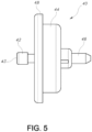
- the valve 40 primarily illustrated in FIG. 5 , is a conventional inverted valve that is used with aerosol cans that are intended to spray foams, gels and liquids, and includes an upper stem 42 with valve opening 43, housing 44 , a lower stem 46 and a side wall 48.
- the valve 40 snaps into the actuator 20 with the attachment lip 28 fitting tightly over and around the side wall 48.
- the upper stem 42 fits tightly into the stem receptacle 24 , with the top of the upper valve stem 42 pressed tightly against the stop 25.
- the valve opening 43 is approximately the same size as the stop opening 27.
- the valve 40 is attached to the can 10 by any suitable means, for example, by using a conventional crimping process, and the lower stem 46 is inserted into the can 10. Pressing the activation lever 26 activates the valve 40 which release the mixture from the can 10.
- the actuator orifice 22 is approximately cylindrical in shape, illustrated in FIGS. 2 and 4 , with a round opening 32 and straight sidewalls 34.
- the opening 32 has a diameter between 0.4 millimeters and 0.9 millimeters, with a preferred diameter of between 0.6 and 0.7 millimeters. In the embodiment shown, the opening 32 is 0.63 millimeters.
- the straight sidewalls 34 are at least 1 millimeter in length, with a preferred length of approximately 2 millimeters.
- the size and shape of the actuator orifice 22 provides for a narrow stream of the mixture that experiences little to no agitation as the mixture exits the can 10 through the valve 40 and actuator 20. As a result, the liquid mixture experiences significant agitation for the first time when it comes into contact with a surface, creating a neat foam line, such as the one illustrated in FIG. 6 , upon impact.
- the vanishing-foam formula includes a surfactant that represents between approximately 3% and 10%, by weight, of the total mixture, preferably approximately 4%.
- the increased percentage of surfactant over conventional formulas for vanishing foams allows for the creation of sufficient foam bubbles when used with an actuator that provides little to no agitation as the formula is delivered onto a surface.
- the surfactant allows the foam to vanish in approximately between 30 seconds and 7 minutes, depending on how much of the mixture is sprayed on one spot on a surface and depending on the external environmental conditions such as the temperature and humidity.
- the remainder of the formula is conventional, and comprises approximately 80% water, between 4% and 16% propellant, with the remainder comprising of conventional preservatives.
- a number of conventional propellants are suitable for use with this formula, such as a mixture of isobutane/propane (A-46), A-45, or Dimethyle Ether (DME).
- the formula is under a relatively low level of pressure, preferably between 60 and 80 PSI. This level of pressure is sufficient to ensure that the flow rate of the vanishing-foam formula exiting the can 10 through the valve 40 and out of the actuator 20 is a constant flow such that no spaces or gaps in mixture exist inside the delivery device 100. Were the flow rate not sufficient, agitation may occur inside of the delivery device 100, thereby causing premature foaming.
- Providing a vanishing foam formula that includes between 3% and 10% surfactant with the delivery device 100 allows a user to stand upright in a common manner, hold the can in an inverted manner and point the can towards the ground at a vertical or near vertical angle and create a narrow stream of vanishing formula that, upon impact, results in a neat line of foam with little to no splattering.
Landscapes
- Chemical & Material Sciences (AREA)
- Engineering & Computer Science (AREA)
- Life Sciences & Earth Sciences (AREA)
- Dispersion Chemistry (AREA)
- Wood Science & Technology (AREA)
- Organic Chemistry (AREA)
- Materials Engineering (AREA)
- Structural Engineering (AREA)
- Architecture (AREA)
- Civil Engineering (AREA)
- Mechanical Engineering (AREA)
- Molecular Biology (AREA)
- Health & Medical Sciences (AREA)
- Chemical Kinetics & Catalysis (AREA)
- Containers And Packaging Bodies Having A Special Means To Remove Contents (AREA)
- Nozzles (AREA)
Description
- The invention relates to foam sprays and devices for the application of such a spray, particularly those that are used to make temporary markings on hard surfaces such as the ground, floor or a playing field.
- Vanishing sprays and vanishing foams are known substances that are frequently used on athletic fields and other surfaces in order to provide a temporary visual marker. The spray is applied from an aerosol can, which is typically small enough to comfortably fit in the user's hand and attach to a holster on user's belt. In order for the foam to be useful, it must create a neat and well defined line that is readily visible and that, depending on the style of actuator, measures on average 1 to 4 inches in width.
- Generally, the foam is created from a liquid mixture that is roughly 80% water, between 4% and 18% propellant (such as butane gas), roughly 1% to 2% surfactant, with the remainder generally comprising preservatives. As the liquid mixture agitates and boils at atmospheric pressure it expands into foam that is typically visible for one to five minutes. In the conventional delivery systems the mixture begins to agitate and boil, thereby beginning the transformation from liquid to foam, as it passes through the actuator, completing the transition from liquid to foam in the air shortly after leaving the can and generally prior to contacting the surface. The conventional actuator has an actuator orifice that is approximately between 3 and 6 millimeters wide, that is curved or angled, and that is bent or partially obstructed so as to create agitation within the actuator.
- As a result of the conventional formula and delivery system, a user must hold the can very near to the ground, typically between two and twelve inches above the surface, to apply the spray and create a useful line on the surface. If the user holds the can any further from the surface the foam results in a wide pattern, ranging on average between at least six inches in width and sometimes measuring over a foot in width on the ground, forming something that resembles a splattering pattern, that is unusable as a reference line, with an inconsistent and sparse concentration of foam, as opposed to the neat and well-formed foam line of highly visible foam that is practical to use. An example of such an ill-formed line is illustrated in
FIG. 7 . -
EP2457622 provides a foaming composition, preferably included in a spray dispensing canister, which is applicable to different surface textures, such as grass, turf, concrete, clay, granite tiles, ceramics, wooden floors and any other surface where it may be required to make temporary marks, regardless of weather conditions such as intense sunlight, heat, cold, rain, etc. -
US2004/221766 provides a foaming aqueous composition to temporarily mark and delimit regulation distances on courts and fields of sports, suitable for use in sport competitions in which it is required to momentarily delimit distances by means of a quick application. -
US2009/032618 andUS6161735 show conventional can and delivery systems. The former relates to a sprayer comprising a motorized liquid spray head or spray pump assembly and includes an operating mechanism adapted to provide the user a push button actuated, automatic power spray for any variety of generally liquid or fluid materials, and the latter relates to a dispensing structure for aerosol containers designed for satisfactory dispensing of aerosol while controlling the discharge rate of the aerosol contained within. - The devices disclosed in both of the above documents have a distinct bend in the nozzle/delivery opening. The delivery tube that extends downwards into the reservoir experiences something near to a 90-degree bend as the tube exits the reservoir and makes its way to the nozzle. In each case, as the mixture is forced out of the device, it will first hit this bend within the delivery device which starts to activate the mixture, meaning that the mixture starts to transition from a liquid to a foam within the delivery device and/or as it exits the device.
- As a result, by the time the mixture/foam reaches the ground surface, it has already been in the expansion process and creates a relatively wide spray of foam rather than a neat line as is the object of the present invention.
-
US2009/032618 discloses the use of different known nozzles that create varying spray patterns but none of those enable the overall device to deliver the solution without first introducing agitation, which, at a minimum, would occur before the solution reaches the nozzle. A relatively complex "actuator assist" disclosed in this application also does not alleviate the prior agitation. - What is needed, therefore, is a vanishing foam formula and delivery device that allows a user to create a neat and well-formed foam line from an upright standing position.
- The invention is a device as claimed in claims 1 to 4 for delivering a vanishing foam formula. The applicator device allows a user to stand upright and spray a neat and well-formed line of foam having little or no splattering or overspray on a surface, the line measuring on average between one and two inches in width and being easy to see from a standing position.
- The applicator device combines a conventional foam-dispensing aerosol can and conventional foam-dispensing valve with an actuator that has a comparatively long and narrow actuator orifice having a cylindrical shape with a round opening and straight sidewalls. The design of the actuator and composition of the formula allow for a narrow spray of the formula that experiences little to no agitation as it leaves the applicator device, thus allowing the agitation and, consequently, the foaming to occur when the spray contacts a surface, such as the ground or the surface of a playing field. The design of the actuator requires that the aerosol can be held in an inverted position to apply the foam to a lower surface. As a result of the applicator device and the formula, the user is able to stand upright and spray a neat foam line having little to no splattering or overspray and maintaining a usable width and density on the surface.
- The vanishing foam formula preferably contains a higher level of surfactant than is found in the conventional formulas so as to provide for sufficient foaming when the formula hits the ground. Such surfactant is not needed with the conventional foam sprays because the conventional foam delivery systems cause significant agitation and foaming to begin as the formula passes through the actuator, which consequently allows for significant foaming to occur prior to the mixture coming into contact with the surface.
- The present invention is described with reference to the accompanying drawings. In the drawings, like reference numbers indicate identical or functionally similar elements. The drawings are not drawn to scale.
-
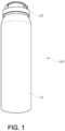
FIG. 1 is a side view of the spray device according to the invention. -
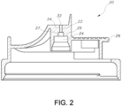
FIG. 2 is a cross section view of the actuator. -
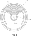
FIG. 3 is a top view of the actuator. -
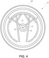
FIG. 4 is a bottom view of the actuator. -
FIG. 5 is a side view of the valve. -
FIG. 6 is an illustration of a neat and well form lined created by the claimed invention. -
FIG. 7 is an illustration of a line formed by the prior art from an upright standing position. - The present invention will now be described more fully in detail with reference to the accompanying drawings, in which the preferred embodiments of the invention are shown.
-
FIGS. 1-5 illustrate thedelivery device 100 according to the invention including a conventional aerosol can 10, anactuator 20, and avalve 40. - The
actuator 20, illustrated inFIGS. 2-4 , includes anactuator orifice 22, avalve stem receptacle 24 that has astop 25 with stop opening 27, anactivation lever 26 and anattachment lip 28. Thevalve 40, primarily illustrated inFIG. 5 , is a conventional inverted valve that is used with aerosol cans that are intended to spray foams, gels and liquids, and includes anupper stem 42 withvalve opening 43,housing 44, alower stem 46 and aside wall 48. - The
valve 40 snaps into theactuator 20 with theattachment lip 28 fitting tightly over and around theside wall 48. Theupper stem 42 fits tightly into thestem receptacle 24, with the top of theupper valve stem 42 pressed tightly against thestop 25. Thevalve opening 43 is approximately the same size as the stop opening 27. Thevalve 40 is attached to thecan 10 by any suitable means, for example, by using a conventional crimping process, and thelower stem 46 is inserted into thecan 10. Pressing theactivation lever 26 activates thevalve 40 which release the mixture from thecan 10. - The
actuator orifice 22 is approximately cylindrical in shape, illustrated inFIGS. 2 and4 , with around opening 32 andstraight sidewalls 34. Theopening 32 has a diameter between 0.4 millimeters and 0.9 millimeters, with a preferred diameter of between 0.6 and 0.7 millimeters. In the embodiment shown, theopening 32 is 0.63 millimeters. Thestraight sidewalls 34 are at least 1 millimeter in length, with a preferred length of approximately 2 millimeters. The size and shape of theactuator orifice 22 provides for a narrow stream of the mixture that experiences little to no agitation as the mixture exits thecan 10 through thevalve 40 andactuator 20. As a result, the liquid mixture experiences significant agitation for the first time when it comes into contact with a surface, creating a neat foam line, such as the one illustrated inFIG. 6 , upon impact. - The vanishing-foam formula includes a surfactant that represents between approximately 3% and 10%, by weight, of the total mixture, preferably approximately 4%. The increased percentage of surfactant over conventional formulas for vanishing foams allows for the creation of sufficient foam bubbles when used with an actuator that provides little to no agitation as the formula is delivered onto a surface. The surfactant allows the foam to vanish in approximately between 30 seconds and 7 minutes, depending on how much of the mixture is sprayed on one spot on a surface and depending on the external environmental conditions such as the temperature and humidity.
- The remainder of the formula is conventional, and comprises approximately 80% water, between 4% and 16% propellant, with the remainder comprising of conventional preservatives. A number of conventional propellants are suitable for use with this formula, such as a mixture of isobutane/propane (A-46), A-45, or Dimethyle Ether (DME).
- Once placed inside the aerosol can 10 the formula is under a relatively low level of pressure, preferably between 60 and 80 PSI. This level of pressure is sufficient to ensure that the flow rate of the vanishing-foam formula exiting the
can 10 through thevalve 40 and out of theactuator 20 is a constant flow such that no spaces or gaps in mixture exist inside thedelivery device 100. Were the flow rate not sufficient, agitation may occur inside of thedelivery device 100, thereby causing premature foaming. - Providing a vanishing foam formula that includes between 3% and 10% surfactant with the
delivery device 100 allows a user to stand upright in a common manner, hold the can in an inverted manner and point the can towards the ground at a vertical or near vertical angle and create a narrow stream of vanishing formula that, upon impact, results in a neat line of foam with little to no splattering.
Claims (4)
- A device (100) for delivering a vanishing foam formula onto a surface, the device comprising:an aerosol can (10) that contains the vanishing foam formula under pressure, an actuator (20) and a valve (40);wherein the actuator (20) includes an actuator orifice (22), a valve stem receptacle (24) having a stop (25) with a stop opening (27), an activation lever (26) and an attachment lip (28); andwherein the valve (40) includes:an upper stem (42) with valve opening (43), wherein valve opening (43) is approximately the same size as the stop opening (27),housing (44),a lower stem (46) and a side wall (48)such that the valve (40) snaps into the actuator (20) with the attachment lip (28) of the actuator (20) fitting tightly over and around the side wall (48) of valve (40), and the upper stem (42) of the valve (40) fits tightly into the stem receptacle (24) of the actuator (20) with the top of the upper valve stem (42) pressed tightly against the stop (25); andwherein the actuator orifice (22) is cylindrical in shape, having a round opening (32) with a diameter between 0.4 millimeters and 0.9 millimeters and straight sidewalls (34) at least 1 millimeter in length, the size and shape of the actuator orifice providing for a narrow stream of the mixture that experiences little or no agitation as the mixture exits the can (10) through the valve (40) and the actuator (20), thereby resulting in the liquid mixture experiencing significant agitation for the first time when it comes in contact with a surface, thus creating a neat foam line upon impact.
- The device (100) of claim 1 wherein the straight sidewalls (34) are between approximately 1.0 and 2.0 millimeters in length.
- The device (100) of claim 2 wherein the pressure in the aerosol can (10) is between approximately 60 and 80 PSI.
- The device (100) of claim 2 or claim 3 wherein the round opening (32) is between approximately 0.6 and 0.7 millimeters.
Applications Claiming Priority (2)
| Application Number | Priority Date | Filing Date | Title |
|---|---|---|---|
| US201662278005P | 2016-01-13 | 2016-01-13 | |
| PCT/US2017/012901 WO2017123565A1 (en) | 2016-01-13 | 2017-01-11 | Stand-and-spray foam delivery method and device thereof |
Publications (3)
| Publication Number | Publication Date |
|---|---|
| EP3402610A1 EP3402610A1 (en) | 2018-11-21 |
| EP3402610A4 EP3402610A4 (en) | 2019-08-14 |
| EP3402610B1 true EP3402610B1 (en) | 2023-06-14 |
Family
ID=59311965
Family Applications (1)
| Application Number | Title | Priority Date | Filing Date |
|---|---|---|---|
| EP17738817.0A Active EP3402610B1 (en) | 2016-01-13 | 2017-01-11 | Stand-and-spray foam delivery method and device thereof |
Country Status (4)
| Country | Link |
|---|---|
| US (1) | US11235226B2 (en) |
| EP (1) | EP3402610B1 (en) |
| CN (1) | CN108472682A (en) |
| WO (1) | WO2017123565A1 (en) |
Families Citing this family (1)
| Publication number | Priority date | Publication date | Assignee | Title |
|---|---|---|---|---|
| NL2034009B1 (en) * | 2023-01-23 | 2024-07-30 | Weener Plastics Group B V | Production of an aerosol dispensing device with a range of nozzle insert types |
Family Cites Families (9)
| Publication number | Priority date | Publication date | Assignee | Title |
|---|---|---|---|---|
| MX172031B (en) * | 1989-12-19 | 1993-11-25 | Precision Valve Corp | FOAM ACTUATOR FOR DOSING A SPRAY PRODUCT |
| JP3651714B2 (en) * | 1996-04-19 | 2005-05-25 | 株式会社丸一 | Trigger type aerosol cap |
| JP3722574B2 (en) | 1996-12-19 | 2005-11-30 | 大正製薬株式会社 | Aerosol container ejection structure |
| HU224750B1 (en) | 2000-03-31 | 2006-01-30 | Chemiker Do Brasil Produtos Au | Process for temporary demarcation of regulation distances in sport |
| US7648083B2 (en) | 2003-12-18 | 2010-01-19 | S.C. Johnson & Son, Inc. | Power sprayer |
| US7213728B2 (en) * | 2004-06-24 | 2007-05-08 | S.C. Johnson & Son, Inc. | Time delay and indicator actuator assembly for aerosol containers |
| US8344056B1 (en) * | 2007-04-04 | 2013-01-01 | Homax Products, Inc. | Aerosol dispensing systems, methods, and compositions for repairing interior structure surfaces |
| AR073346A1 (en) * | 2009-07-21 | 2010-11-03 | Silva Pablo Cesar | FOAM TRAINING COMPOSITION FOR THE GENERATION OF SHARED TEMPORARY DURATION SIGNALS |
| US8802058B2 (en) | 2010-04-19 | 2014-08-12 | Gelmed, Llc | Pharmaceutical compositions and methods for administering the same |
-
2017
- 2017-01-11 EP EP17738817.0A patent/EP3402610B1/en active Active
- 2017-01-11 US US16/067,359 patent/US11235226B2/en active Active
- 2017-01-11 CN CN201780006457.5A patent/CN108472682A/en active Pending
- 2017-01-11 WO PCT/US2017/012901 patent/WO2017123565A1/en not_active Ceased
Also Published As
| Publication number | Publication date |
|---|---|
| US20190015733A1 (en) | 2019-01-17 |
| EP3402610A1 (en) | 2018-11-21 |
| EP3402610A4 (en) | 2019-08-14 |
| WO2017123565A1 (en) | 2017-07-20 |
| US11235226B2 (en) | 2022-02-01 |
| CA3011510A1 (en) | 2017-07-20 |
| CN108472682A (en) | 2018-08-31 |
Similar Documents
| Publication | Publication Date | Title |
|---|---|---|
| CN100560220C (en) | Spray nozzle | |
| US20250214104A1 (en) | Texturizing a wall or ceiling with non-acoustical joint compound | |
| US8820665B2 (en) | Fluid dispensing nozzle | |
| WO2000010889A3 (en) | Actuator system for spraying a formulation onto a host | |
| US20210016310A1 (en) | Turf Printing and Removal Using Foaming Carrier | |
| US20160184847A1 (en) | Vortex mixing and ratio adjustment system | |
| US20160243570A1 (en) | Electric tank dispenser having a pressurizable space and selectable pressure levels | |
| EP3402610B1 (en) | Stand-and-spray foam delivery method and device thereof | |
| EP3349913B1 (en) | Modified spray head | |
| CA3011510C (en) | Stand-and-spray foam delivery method and device thereof | |
| GB2581751A (en) | Weed control | |
| EP3349912B1 (en) | Modified spray head | |
| US9010271B2 (en) | Method and system to whiten a golf hole | |
| US20050077386A1 (en) | Foamer | |
| US9889457B1 (en) | Applicator for dispensing gardening liquids | |
| KR20170129355A (en) | Nozzle for spray | |
| KR20150003221U (en) | A spray type straw | |
| WO2002076186A3 (en) | A device for dispensing liquids |
Legal Events
| Date | Code | Title | Description |
|---|---|---|---|
| STAA | Information on the status of an ep patent application or granted ep patent |
Free format text: STATUS: THE INTERNATIONAL PUBLICATION HAS BEEN MADE |
|
| PUAI | Public reference made under article 153(3) epc to a published international application that has entered the european phase |
Free format text: ORIGINAL CODE: 0009012 |
|
| STAA | Information on the status of an ep patent application or granted ep patent |
Free format text: STATUS: REQUEST FOR EXAMINATION WAS MADE |
|
| 17P | Request for examination filed |
Effective date: 20180808 |
|
| AK | Designated contracting states |
Kind code of ref document: A1 Designated state(s): AL AT BE BG CH CY CZ DE DK EE ES FI FR GB GR HR HU IE IS IT LI LT LU LV MC MK MT NL NO PL PT RO RS SE SI SK SM TR |
|
| AX | Request for extension of the european patent |
Extension state: BA ME |
|
| DAV | Request for validation of the european patent (deleted) | ||
| DAX | Request for extension of the european patent (deleted) | ||
| A4 | Supplementary search report drawn up and despatched |
Effective date: 20190717 |
|
| RIC1 | Information provided on ipc code assigned before grant |
Ipc: B05B 11/04 20060101ALI20190711BHEP Ipc: C09D 5/02 20060101ALI20190711BHEP Ipc: B05D 7/24 20060101ALI20190711BHEP Ipc: B05D 1/02 20060101AFI20190711BHEP |
|
| STAA | Information on the status of an ep patent application or granted ep patent |
Free format text: STATUS: EXAMINATION IS IN PROGRESS |
|
| 17Q | First examination report despatched |
Effective date: 20200218 |
|
| GRAP | Despatch of communication of intention to grant a patent |
Free format text: ORIGINAL CODE: EPIDOSNIGR1 |
|
| STAA | Information on the status of an ep patent application or granted ep patent |
Free format text: STATUS: GRANT OF PATENT IS INTENDED |
|
| INTG | Intention to grant announced |
Effective date: 20230123 |
|
| RIN1 | Information on inventor provided before grant (corrected) |
Inventor name: SNIPER, TODD Inventor name: RECORD, JASON |
|
| GRAS | Grant fee paid |
Free format text: ORIGINAL CODE: EPIDOSNIGR3 |
|
| GRAA | (expected) grant |
Free format text: ORIGINAL CODE: 0009210 |
|
| STAA | Information on the status of an ep patent application or granted ep patent |
Free format text: STATUS: THE PATENT HAS BEEN GRANTED |
|
| AK | Designated contracting states |
Kind code of ref document: B1 Designated state(s): AL AT BE BG CH CY CZ DE DK EE ES FI FR GB GR HR HU IE IS IT LI LT LU LV MC MK MT NL NO PL PT RO RS SE SI SK SM TR |
|
| REG | Reference to a national code |
Ref country code: CH Ref legal event code: EP |
|
| REG | Reference to a national code |
Ref country code: DE Ref legal event code: R096 Ref document number: 602017070190 Country of ref document: DE |
|
| REG | Reference to a national code |
Ref country code: AT Ref legal event code: REF Ref document number: 1578841 Country of ref document: AT Kind code of ref document: T Effective date: 20230715 |
|
| REG | Reference to a national code |
Ref country code: LT Ref legal event code: MG9D |
|
| REG | Reference to a national code |
Ref country code: NL Ref legal event code: MP Effective date: 20230614 |
|
| PG25 | Lapsed in a contracting state [announced via postgrant information from national office to epo] |
Ref country code: SE Free format text: LAPSE BECAUSE OF FAILURE TO SUBMIT A TRANSLATION OF THE DESCRIPTION OR TO PAY THE FEE WITHIN THE PRESCRIBED TIME-LIMIT Effective date: 20230614 Ref country code: NO Free format text: LAPSE BECAUSE OF FAILURE TO SUBMIT A TRANSLATION OF THE DESCRIPTION OR TO PAY THE FEE WITHIN THE PRESCRIBED TIME-LIMIT Effective date: 20230914 Ref country code: ES Free format text: LAPSE BECAUSE OF FAILURE TO SUBMIT A TRANSLATION OF THE DESCRIPTION OR TO PAY THE FEE WITHIN THE PRESCRIBED TIME-LIMIT Effective date: 20230614 |
|
| REG | Reference to a national code |
Ref country code: AT Ref legal event code: MK05 Ref document number: 1578841 Country of ref document: AT Kind code of ref document: T Effective date: 20230614 |
|
| PG25 | Lapsed in a contracting state [announced via postgrant information from national office to epo] |
Ref country code: RS Free format text: LAPSE BECAUSE OF FAILURE TO SUBMIT A TRANSLATION OF THE DESCRIPTION OR TO PAY THE FEE WITHIN THE PRESCRIBED TIME-LIMIT Effective date: 20230614 Ref country code: NL Free format text: LAPSE BECAUSE OF FAILURE TO SUBMIT A TRANSLATION OF THE DESCRIPTION OR TO PAY THE FEE WITHIN THE PRESCRIBED TIME-LIMIT Effective date: 20230614 Ref country code: LV Free format text: LAPSE BECAUSE OF FAILURE TO SUBMIT A TRANSLATION OF THE DESCRIPTION OR TO PAY THE FEE WITHIN THE PRESCRIBED TIME-LIMIT Effective date: 20230614 Ref country code: LT Free format text: LAPSE BECAUSE OF FAILURE TO SUBMIT A TRANSLATION OF THE DESCRIPTION OR TO PAY THE FEE WITHIN THE PRESCRIBED TIME-LIMIT Effective date: 20230614 Ref country code: HR Free format text: LAPSE BECAUSE OF FAILURE TO SUBMIT A TRANSLATION OF THE DESCRIPTION OR TO PAY THE FEE WITHIN THE PRESCRIBED TIME-LIMIT Effective date: 20230614 Ref country code: GR Free format text: LAPSE BECAUSE OF FAILURE TO SUBMIT A TRANSLATION OF THE DESCRIPTION OR TO PAY THE FEE WITHIN THE PRESCRIBED TIME-LIMIT Effective date: 20230915 |
|
| PG25 | Lapsed in a contracting state [announced via postgrant information from national office to epo] |
Ref country code: FI Free format text: LAPSE BECAUSE OF FAILURE TO SUBMIT A TRANSLATION OF THE DESCRIPTION OR TO PAY THE FEE WITHIN THE PRESCRIBED TIME-LIMIT Effective date: 20230614 |
|
| PG25 | Lapsed in a contracting state [announced via postgrant information from national office to epo] |
Ref country code: SK Free format text: LAPSE BECAUSE OF FAILURE TO SUBMIT A TRANSLATION OF THE DESCRIPTION OR TO PAY THE FEE WITHIN THE PRESCRIBED TIME-LIMIT Effective date: 20230614 |
|
| PG25 | Lapsed in a contracting state [announced via postgrant information from national office to epo] |
Ref country code: IS Free format text: LAPSE BECAUSE OF FAILURE TO SUBMIT A TRANSLATION OF THE DESCRIPTION OR TO PAY THE FEE WITHIN THE PRESCRIBED TIME-LIMIT Effective date: 20231014 |
|
| PG25 | Lapsed in a contracting state [announced via postgrant information from national office to epo] |
Ref country code: SM Free format text: LAPSE BECAUSE OF FAILURE TO SUBMIT A TRANSLATION OF THE DESCRIPTION OR TO PAY THE FEE WITHIN THE PRESCRIBED TIME-LIMIT Effective date: 20230614 Ref country code: SK Free format text: LAPSE BECAUSE OF FAILURE TO SUBMIT A TRANSLATION OF THE DESCRIPTION OR TO PAY THE FEE WITHIN THE PRESCRIBED TIME-LIMIT Effective date: 20230614 Ref country code: RO Free format text: LAPSE BECAUSE OF FAILURE TO SUBMIT A TRANSLATION OF THE DESCRIPTION OR TO PAY THE FEE WITHIN THE PRESCRIBED TIME-LIMIT Effective date: 20230614 Ref country code: PT Free format text: LAPSE BECAUSE OF FAILURE TO SUBMIT A TRANSLATION OF THE DESCRIPTION OR TO PAY THE FEE WITHIN THE PRESCRIBED TIME-LIMIT Effective date: 20231016 Ref country code: IS Free format text: LAPSE BECAUSE OF FAILURE TO SUBMIT A TRANSLATION OF THE DESCRIPTION OR TO PAY THE FEE WITHIN THE PRESCRIBED TIME-LIMIT Effective date: 20231014 Ref country code: EE Free format text: LAPSE BECAUSE OF FAILURE TO SUBMIT A TRANSLATION OF THE DESCRIPTION OR TO PAY THE FEE WITHIN THE PRESCRIBED TIME-LIMIT Effective date: 20230614 Ref country code: CZ Free format text: LAPSE BECAUSE OF FAILURE TO SUBMIT A TRANSLATION OF THE DESCRIPTION OR TO PAY THE FEE WITHIN THE PRESCRIBED TIME-LIMIT Effective date: 20230614 Ref country code: AT Free format text: LAPSE BECAUSE OF FAILURE TO SUBMIT A TRANSLATION OF THE DESCRIPTION OR TO PAY THE FEE WITHIN THE PRESCRIBED TIME-LIMIT Effective date: 20230614 |
|
| PG25 | Lapsed in a contracting state [announced via postgrant information from national office to epo] |
Ref country code: PL Free format text: LAPSE BECAUSE OF FAILURE TO SUBMIT A TRANSLATION OF THE DESCRIPTION OR TO PAY THE FEE WITHIN THE PRESCRIBED TIME-LIMIT Effective date: 20230614 |
|
| REG | Reference to a national code |
Ref country code: DE Ref legal event code: R097 Ref document number: 602017070190 Country of ref document: DE |
|
| PLBE | No opposition filed within time limit |
Free format text: ORIGINAL CODE: 0009261 |
|
| STAA | Information on the status of an ep patent application or granted ep patent |
Free format text: STATUS: NO OPPOSITION FILED WITHIN TIME LIMIT |
|
| PG25 | Lapsed in a contracting state [announced via postgrant information from national office to epo] |
Ref country code: DK Free format text: LAPSE BECAUSE OF FAILURE TO SUBMIT A TRANSLATION OF THE DESCRIPTION OR TO PAY THE FEE WITHIN THE PRESCRIBED TIME-LIMIT Effective date: 20230614 |
|
| PG25 | Lapsed in a contracting state [announced via postgrant information from national office to epo] |
Ref country code: SI Free format text: LAPSE BECAUSE OF FAILURE TO SUBMIT A TRANSLATION OF THE DESCRIPTION OR TO PAY THE FEE WITHIN THE PRESCRIBED TIME-LIMIT Effective date: 20230614 |
|
| 26N | No opposition filed |
Effective date: 20240315 |
|
| PG25 | Lapsed in a contracting state [announced via postgrant information from national office to epo] |
Ref country code: SI Free format text: LAPSE BECAUSE OF FAILURE TO SUBMIT A TRANSLATION OF THE DESCRIPTION OR TO PAY THE FEE WITHIN THE PRESCRIBED TIME-LIMIT Effective date: 20230614 Ref country code: IT Free format text: LAPSE BECAUSE OF FAILURE TO SUBMIT A TRANSLATION OF THE DESCRIPTION OR TO PAY THE FEE WITHIN THE PRESCRIBED TIME-LIMIT Effective date: 20230614 |
|
| REG | Reference to a national code |
Ref country code: DE Ref legal event code: R119 Ref document number: 602017070190 Country of ref document: DE |
|
| PG25 | Lapsed in a contracting state [announced via postgrant information from national office to epo] |
Ref country code: MC Free format text: LAPSE BECAUSE OF FAILURE TO SUBMIT A TRANSLATION OF THE DESCRIPTION OR TO PAY THE FEE WITHIN THE PRESCRIBED TIME-LIMIT Effective date: 20230614 |
|
| PG25 | Lapsed in a contracting state [announced via postgrant information from national office to epo] |
Ref country code: MC Free format text: LAPSE BECAUSE OF FAILURE TO SUBMIT A TRANSLATION OF THE DESCRIPTION OR TO PAY THE FEE WITHIN THE PRESCRIBED TIME-LIMIT Effective date: 20230614 |
|
| PG25 | Lapsed in a contracting state [announced via postgrant information from national office to epo] |
Ref country code: LU Free format text: LAPSE BECAUSE OF NON-PAYMENT OF DUE FEES Effective date: 20240111 |
|
| PG25 | Lapsed in a contracting state [announced via postgrant information from national office to epo] |
Ref country code: LU Free format text: LAPSE BECAUSE OF NON-PAYMENT OF DUE FEES Effective date: 20240111 |
|
| PG25 | Lapsed in a contracting state [announced via postgrant information from national office to epo] |
Ref country code: DE Free format text: LAPSE BECAUSE OF NON-PAYMENT OF DUE FEES Effective date: 20240801 |
|
| PG25 | Lapsed in a contracting state [announced via postgrant information from national office to epo] |
Ref country code: FR Free format text: LAPSE BECAUSE OF NON-PAYMENT OF DUE FEES Effective date: 20240131 |
|
| PG25 | Lapsed in a contracting state [announced via postgrant information from national office to epo] |
Ref country code: FR Free format text: LAPSE BECAUSE OF NON-PAYMENT OF DUE FEES Effective date: 20240131 Ref country code: DE Free format text: LAPSE BECAUSE OF NON-PAYMENT OF DUE FEES Effective date: 20240801 |
|
| PG25 | Lapsed in a contracting state [announced via postgrant information from national office to epo] |
Ref country code: BG Free format text: LAPSE BECAUSE OF FAILURE TO SUBMIT A TRANSLATION OF THE DESCRIPTION OR TO PAY THE FEE WITHIN THE PRESCRIBED TIME-LIMIT Effective date: 20230614 |
|
| PG25 | Lapsed in a contracting state [announced via postgrant information from national office to epo] |
Ref country code: BG Free format text: LAPSE BECAUSE OF FAILURE TO SUBMIT A TRANSLATION OF THE DESCRIPTION OR TO PAY THE FEE WITHIN THE PRESCRIBED TIME-LIMIT Effective date: 20230614 |
|
| PG25 | Lapsed in a contracting state [announced via postgrant information from national office to epo] |
Ref country code: IE Free format text: LAPSE BECAUSE OF NON-PAYMENT OF DUE FEES Effective date: 20240111 |
|
| PG25 | Lapsed in a contracting state [announced via postgrant information from national office to epo] |
Ref country code: IE Free format text: LAPSE BECAUSE OF NON-PAYMENT OF DUE FEES Effective date: 20240111 |
|
| PG25 | Lapsed in a contracting state [announced via postgrant information from national office to epo] |
Ref country code: CY Free format text: LAPSE BECAUSE OF FAILURE TO SUBMIT A TRANSLATION OF THE DESCRIPTION OR TO PAY THE FEE WITHIN THE PRESCRIBED TIME-LIMIT; INVALID AB INITIO Effective date: 20170111 |
|
| PG25 | Lapsed in a contracting state [announced via postgrant information from national office to epo] |
Ref country code: HU Free format text: LAPSE BECAUSE OF FAILURE TO SUBMIT A TRANSLATION OF THE DESCRIPTION OR TO PAY THE FEE WITHIN THE PRESCRIBED TIME-LIMIT; INVALID AB INITIO Effective date: 20170111 |
|
| PG25 | Lapsed in a contracting state [announced via postgrant information from national office to epo] |
Ref country code: TR Free format text: LAPSE BECAUSE OF FAILURE TO SUBMIT A TRANSLATION OF THE DESCRIPTION OR TO PAY THE FEE WITHIN THE PRESCRIBED TIME-LIMIT Effective date: 20230614 |
|
| REG | Reference to a national code |
Ref country code: CH Ref legal event code: U11 Free format text: ST27 STATUS EVENT CODE: U-0-0-U10-U11 (AS PROVIDED BY THE NATIONAL OFFICE) Effective date: 20260201 |
|
| PGFP | Annual fee paid to national office [announced via postgrant information from national office to epo] |
Ref country code: GB Payment date: 20260105 Year of fee payment: 10 |
|
| PGFP | Annual fee paid to national office [announced via postgrant information from national office to epo] |
Ref country code: BE Payment date: 20260121 Year of fee payment: 10 |
|
| PGFP | Annual fee paid to national office [announced via postgrant information from national office to epo] |
Ref country code: CH Payment date: 20260201 Year of fee payment: 10 |