EP3402318A1 - 4-post rack with integrated intake/exhaust regions - Google Patents
4-post rack with integrated intake/exhaust regions Download PDFInfo
- Publication number
- EP3402318A1 EP3402318A1 EP18170619.3A EP18170619A EP3402318A1 EP 3402318 A1 EP3402318 A1 EP 3402318A1 EP 18170619 A EP18170619 A EP 18170619A EP 3402318 A1 EP3402318 A1 EP 3402318A1
- Authority
- EP
- European Patent Office
- Prior art keywords
- plenum
- electronic equipment
- rack
- support structure
- sealing panel
- Prior art date
- Legal status (The legal status is an assumption and is not a legal conclusion. Google has not performed a legal analysis and makes no representation as to the accuracy of the status listed.)
- Withdrawn
Links
- 238000007789 sealing Methods 0.000 claims abstract description 49
- 239000000463 material Substances 0.000 claims description 10
- 239000012530 fluid Substances 0.000 claims description 9
- 230000004888 barrier function Effects 0.000 claims description 7
- 229920001971 elastomer Polymers 0.000 claims description 4
- 239000005060 rubber Substances 0.000 claims description 4
- 230000001419 dependent effect Effects 0.000 claims 1
- 238000009434 installation Methods 0.000 description 6
- 230000004048 modification Effects 0.000 description 4
- 238000012986 modification Methods 0.000 description 4
- 238000000926 separation method Methods 0.000 description 3
- 238000001816 cooling Methods 0.000 description 1
- 229920003052 natural elastomer Polymers 0.000 description 1
- 229920001194 natural rubber Polymers 0.000 description 1
- 229920003051 synthetic elastomer Polymers 0.000 description 1
- 239000005061 synthetic rubber Substances 0.000 description 1
- 238000009423 ventilation Methods 0.000 description 1
Images






Classifications
-
- H—ELECTRICITY
- H05—ELECTRIC TECHNIQUES NOT OTHERWISE PROVIDED FOR
- H05K—PRINTED CIRCUITS; CASINGS OR CONSTRUCTIONAL DETAILS OF ELECTRIC APPARATUS; MANUFACTURE OF ASSEMBLAGES OF ELECTRICAL COMPONENTS
- H05K7/00—Constructional details common to different types of electric apparatus
- H05K7/20—Modifications to facilitate cooling, ventilating, or heating
- H05K7/20709—Modifications to facilitate cooling, ventilating, or heating for server racks or cabinets; for data centers, e.g. 19-inch computer racks
- H05K7/20718—Forced ventilation of a gaseous coolant
- H05K7/20736—Forced ventilation of a gaseous coolant within cabinets for removing heat from server blades
-
- H—ELECTRICITY
- H05—ELECTRIC TECHNIQUES NOT OTHERWISE PROVIDED FOR
- H05K—PRINTED CIRCUITS; CASINGS OR CONSTRUCTIONAL DETAILS OF ELECTRIC APPARATUS; MANUFACTURE OF ASSEMBLAGES OF ELECTRICAL COMPONENTS
- H05K7/00—Constructional details common to different types of electric apparatus
- H05K7/20—Modifications to facilitate cooling, ventilating, or heating
- H05K7/20536—Modifications to facilitate cooling, ventilating, or heating for racks or cabinets of standardised dimensions, e.g. electronic racks for aircraft or telecommunication equipment
- H05K7/20554—Forced ventilation of a gaseous coolant
- H05K7/20572—Forced ventilation of a gaseous coolant within cabinets for removing heat from sub-racks, e.g. plenum
-
- H—ELECTRICITY
- H05—ELECTRIC TECHNIQUES NOT OTHERWISE PROVIDED FOR
- H05K—PRINTED CIRCUITS; CASINGS OR CONSTRUCTIONAL DETAILS OF ELECTRIC APPARATUS; MANUFACTURE OF ASSEMBLAGES OF ELECTRICAL COMPONENTS
- H05K7/00—Constructional details common to different types of electric apparatus
- H05K7/14—Mounting supporting structure in casing or on frame or rack
- H05K7/1485—Servers; Data center rooms, e.g. 19-inch computer racks
- H05K7/1488—Cabinets therefor, e.g. chassis or racks or mechanical interfaces between blades and support structures
- H05K7/1489—Cabinets therefor, e.g. chassis or racks or mechanical interfaces between blades and support structures characterized by the mounting of blades therein, e.g. brackets, rails, trays
-
- H—ELECTRICITY
- H05—ELECTRIC TECHNIQUES NOT OTHERWISE PROVIDED FOR
- H05K—PRINTED CIRCUITS; CASINGS OR CONSTRUCTIONAL DETAILS OF ELECTRIC APPARATUS; MANUFACTURE OF ASSEMBLAGES OF ELECTRICAL COMPONENTS
- H05K7/00—Constructional details common to different types of electric apparatus
- H05K7/20—Modifications to facilitate cooling, ventilating, or heating
- H05K7/20009—Modifications to facilitate cooling, ventilating, or heating using a gaseous coolant in electronic enclosures
- H05K7/20136—Forced ventilation, e.g. by fans
- H05K7/20145—Means for directing air flow, e.g. ducts, deflectors, plenum or guides
Definitions
- the invention relates to a 4-post rack, and more particularly, the invention relates to a 4-post rack having integrated ventilation regions.
- thermal management systems are designed to segregate the hot air of network equipment exhaust from the cool or cold air intake region of the data center, making the cooling system more efficient. This is accomplished by installing intake and exhaust ducts mounted adjacent to rack mounted switches that employ side to side airflow.
- Previous rack mounted solutions were designed to be mounted behind vertical cable managers installed on each side of the racks. The position of the ducts behind the vertical cable managers effectively blocks any use of pass through features and vertical patch panel mounting provided by the vertical cable managers.
- a first aspect of the invention is directed to an electronic equipment rack.
- the electronic equipment rack comprises a support structure, a first plenum, a second plenum, and a sealing panel.
- the support structure has a plurality of post members configured to form a cage having a front, a back, a top, a bottom, a first lateral side, and a second lateral side and defining a space therebetween.
- the first plenum is arranged along the first lateral side of the support structure.
- the second plenum is arranged along the second lateral side of the support structure.
- the first sealing panel defines a first wall of the first plenum and has a length extending substantially from the top of the support structure to the bottom of the support structure. A portion of the first sealing member is selectively removable to define an intake port in the first plenum.
- a second aspect of the invention is also directed to an electronic equipment rack.
- This electronic equipment rack comprises a support structure, a first plenum, a second plenum, and a plurality of baffles.
- the support structure has a plurality of post members configured to form a cage having a front, a back, a top, a bottom, a first lateral side, and a second lateral side and defining a space therebetween.
- the first plenum is arranged along the first lateral side of the support structure, and the second plenum is arranged along the second lateral side of the support structure.
- a plurality of baffles is located within each plenum.
- the baffles are adjustable to selectively delimit a first volume of an intake duct associated with the first plenum and a second volume of an exhaust duct associated with the second plenum.
- the arrangement of the baffles established an air flow path from the intake duct to the exhaust duct across an electronic equipment supported within the cage.
- a third aspect of the invention is also directed to an electronic equipment rack.
- the electronic equipment rack comprises a support structure, an intake duct, an exhaust duct, and a baffle arrangement.
- the support structure comprises a plurality of post members configured to form a cage having a front, a back, a top, a bottom, a first lateral side, and a second lateral side and defining a space therebetween.
- the intake duct is located along the first lateral side and is in fluid communication with the space.
- the exhaust duct is located on the second lateral side and is in fluid communication with the intake port via the space.
- the baffle arrangement is configured to isolate a hot side of the space associated with one of the front or back of the support structure from a cool side of the space associated with the other of the front or back of the support structure. This creates a thermal barrier within the space to promote a temperature differential within the space.
- a first volume of the space exhibits a first temperature which is lower than a second temperature exhibited by a second volume of the space.
- a portion of a boundary between the hot side and the cool side is substantially defined by a panel of an electronic equipment supported within the space by the support structure.
- the present invention is a modification to existing 4-post racks.
- the assembly consists of side weldments of the rack using extended horizontal top and bottom brackets to create an open area between electronic equipment mount posts or rails and an outer side surface of the rack.
- Vertical posts or channels at each corner and front to back brackets complete the assembly of a new, wider 4-post rack.
- the additional vertical posts or channels at each corner of the rack include mount slots at 1 rack unit spacing for the installation of baffles or shelves which act as the top and bottom surfaces of intake and exhaust ducts. End panels installed to each side of the rack act as the outer surfaces of intake and exhaust regions.
- the new 4-post rack assembly is shown in FIGS. 1 and 2 , configured with two (2) PEVF vertical cable managers having electronic switches and patch panels installed, a side air flow rack mounted network switch, and intake/exhaust regions formed adjacent the switch.
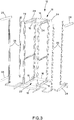
- FIGS. 3 through 9 Modifications to an existing 4-post rack assembly are shown in FIGS. 3 through 9 .
- the new intake/exhaust ducts are shown in FIGS. 10 through 14 . These ducts can be installed on either side of the rack and can be used as an intake or exhaust. They are preferably identical.
- FIG. 15 Installation of a vertical cable manager 42 is shown in FIG. 15 .
- FIG. 16 Installation of a new power distribution unit mount bracket is shown in FIG. 16 .
- An electronic equipment rack 10 includes a typical support structure 12 (see FIG. 3 ) made up of four spaced vertical posts 14 joined by 8 horizontal posts 16 to form a cage 18 having a cuboid shape defining a space 20 where one or more pieces of electronic equipment 22 can be supported.
- Front and rear, upper and lower horizontal posts 16 include outwardly flared flanges 24 such that each corner of the cuboid cage 18 has a laterally extending bracket to which four additional vertical posts 26 are attached.
- These additional posts 26 can be joined by further horizontal posts 28 as needed to provide sufficient rigidity to the rack 10.
- the posts of various orientations are attached to each other by fasteners known in the art such as suitable mechanical fasteners and welds.
- the posts can be roll formed wherein horizontal and vertical posts are integral with one another in a unibody form.
- a top 30 of the rack 10 is at least partially enclosed by a panel 32.
- the panel 32 is fastened to horizontal posts 16 at the upper end of the rack 10.
- the panel 32 includes a brush entry 34 that can be rotated 180° to position the brush entry 34 towards the front or rear of the rack 10 as required.
- the brush entry 34 maintains a seal with the rack 10 for thermal containment.
- the four additional vertical posts 26 are positioned at each corner of the rack 10 and contain mount slots 36 ( FIG. 11 ) at 1 rack unit spacing for the installation of shelves which act as top and bottom baffles within intake and exhaust ducts as will be described in more detail below.
- Each plenum 38 has an enclosed lateral sidewall 40 extending from the front to the rear and from the top to the bottom of the rack 10.
- the sidewalls 40 are generally produced from a sheet material, typically rigid, and may be produced in sections or panels as shown. Edges of the sidewalls 40 are attached to the four additional vertical posts 26 and upper and lower horizontal posts 28 that join front posts to rear posts. As shown, the top and bottom sidewall panels 40 attach to the additional four posts using fasteners, for example machine screws.
- the sidewall panels 40 form laterally outer walls of the plenums 38.
- a vertical cable manager 42 can be installed to the rack 10 assembly as depicted in, for example, FIGS. 1 and 2 .
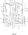
- the front and back walls of the plenums 38 are enclosed by similar or identical sealing panels 44. Portions of the sealing panels 44 are selectively removable to define one or more intake ports 46 ( FIG. 12 ) on one lateral side of the rack 10 and one or more exhaust ports 48 on the opposing lateral side of the rack 10. Corresponding intake and exhaust ports 48 are preferably created on the front and back walls of the plenums 38 to allow maximum airflow from both front and back directions.
- the sealing panels 44 are produced from a pliable material, for example a natural or synthetic rubber.
- the sealing panels 44 are rubber flaps installed on each side of the rack 10 to close front and back walls of the plenums. These flap seals maintain a separation of hot and cool sides of the rack 10.
- the rubber flap seals are cut and removed from the rack 10 at the positions where intake ports 46 and exhaust ports 48 are desired, for example on opposing sides of an electronic equipment 22 supported within the space 20 by the support structure 12.
- Brackets 50 are provided to attach at least one edge of the sealing panels 44 to the rack 10 and over the plenums 38. One lengthwise edge of the sealing panels 44 may remain free from attachment in sealing engagement with a post.
- the rack 10 includes a plurality of baffles within each plenum 38.
- the baffles are adjustable to selectively delimit a volume of an intake duct 52 associated with a first plenum 38 and a volume of an exhaust duct 54 associated with a second plenum 38 on the opposite lateral side of the rack 10 from the first plenum 38.
- the plurality of baffles includes cross baffles 56 and upright baffles 58.
- the cross baffles 56 are generally oriented horizontally within the plenums 38 to delimit a height of the intake and exhaust ducts 52, 54. A distance from an upper cross baffle 56 to a lower cross baffle 56 defines the upper and lower limits of the intake and exhaust ducts 52, 54 of the rack 10.
- the cross baffles 56 take a similar structure to that of a shelf within each plenum.
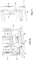
- the cross baffles 56 include formed tabs at each end which allow the cross baffles 56 to be clipped in place to the rack 10 vertical posts 14 as shown in FIGS. 10-11 .
- the rack 10 posts have rectangular cutouts at 1 rack unit spacing to position upper and lower cross baffles 56 at a required rack location in the rack 10 to selectively define the height of the duct.
- an upper cross baffle 56 is positioned eight rack units (14 ins.) above a lower cross baffle 56.
- a bottom cross baffle 56 is clipped in place at a 1 rack unit position. This establishes a lower limit of the duct.
- a top cross baffle 56 is installed and is adjusted to match the desired height of the duct.
- the upper cross baffle 56 will correspond to the uppermost edge corner of the electronic equipment 22 housing, and the lower cross baffle 56 will correspond to the lowermost edge corner of the electronic equipment 22 housing parallel to the uppermost edge corner.
- the cross baffles 56 are outfitted with electronic equipment seals 60 which extend inwardly into the space 20 from edges of the cross baffles 56.
- These equipment seals 60 are generally flap seals attached to flanges on the cross baffles 56 to form a seal against the rack 10 mounted electronic equipment 22.
- the electronic equipment seals 60 are configured to engage an electronic equipment 22 supported within the space 20 by the support structure 12.
- upright baffles 58 or side baffles further delimit the volume of the intake and exhaust ducts 52, 54.
- the upright baffles 58 delimit widths of the intake and exhaust ducts 52, 54.
- the upright baffles 58 are attached to and extend from the upper cross baffle 56 to the lower cross baffle 56 and close interior sidewalls of the intake and exhaust ducts 52, 54 relative to the space 20.
- these upright baffles 58 have a length/height of 8 rack units.
- the upright baffles 58 are positioned to match the depth of the electronic equipment 22 as it is mounted within the space 20. This creates a thermal barrier between the intake/exhaust ducts 52, 54 and a volume behind the electronic equipment 22 through which cables can be run to and from the electronic equipment 22.
- the cabling is isolated from a hot zone of the rack 10.
- an arrangement of baffles creates an air flow path in which a flow of air enters the first plenum 38 via the intake port or ports 46 and across the space 20 to the exhaust port or ports 48 in the second plenum.
- the baffle arrangement includes a plurality of baffles located within the first plenum 38 and the second plenum 38 which are adjustable to selectively delimit a first volume of an intake duct 52 associated with the first plenum 38 and delimit a second volume of an exhaust duct 54 within the second plenum 38.
- An electronic equipment 22 supported within the space 20 by the support structure 12 provides a fluid communication between the intake duct 52 and the exhaust duct 54.
- the arrangement of the plurality of baffles creates a thermal barrier between a volume of the rack 10 delimited by the plurality of baffles and at least one of a front or rear portion of the electronic equipment 22 supported in the space 20 between the intake duct 52 and the exhaust duct 54.
- the arrangement of baffles is configured to isolate a hot side 62 of the space 20 associated with one of the front or back of the support structure 12 from a cool side 64 of the space 20 associated with the other of the front or back of the support structure 12 by creating a thermal barrier within the space 20.
- This promotes a temperature differential within the space 20 wherein a first volume of the space 20 within the cool side 64 exhibits a first temperature which is lower than a second temperature exhibited by a second volume of the space 20 on the hot side 62 in which the electronic equipment 22 is mounted.
- a portion of a boundary between the hot side 62 and the cool side 64 is substantially defined a front or back panel 66 of the electronic equipment 22 supported within the space 20 by the support structure 12.
- an intermediate cross baffle 56 can be inserted between the upper cross baffle 56 and the lower cross baffle 56 when the electronic equipment 22 has a height less than 8 rack units.
- the rack 10 can have multiple intake and exhaust ducts 52,54 as needed by simply removing further portions of the sealing panels 44 and providing additional cross baffles 56 and upright baffles 58 in the manner described above.
- the person of ordinary skill in the art would merely repeat the structures thus far described at different rack heights to produce the same result.
- a vertical cable manager 42 is attached to the outer lateral sides 40 of the plenums 38.
- Weld nuts are supplied on the inside of the rack vertical posts 26 to allow mounting of the vertical cable manager 42 at three locations. This allows for the attachment of the vertical cable manager 42 without requiring access to the intake and exhaust ducts 52,54 of the rack 10.
- a vertical cable manager cover mount bracket 68 is fastened a cover 70 to the rack assembly front to back post. Pass through holes can be removed to maintain hot/cool side thermal separation.
- the rack 10 includes power distribution unit mount brackets 72. These brackets 72 are secured to the rack vertical posts 14 and wrap around to the back of the rack 10. The brackets 72 are installed on the intake side of the rack 10 as to not interfere with the exhaust ducts 54. One or more power distribution units 74 are mounted to the brackets 72 through keyholes on the mount brackets 72. Mount holes at multiple locations on the rack vertical post allow for the installation of various size power distribution units 74.
Landscapes
- Engineering & Computer Science (AREA)
- Microelectronics & Electronic Packaging (AREA)
- Physics & Mathematics (AREA)
- Thermal Sciences (AREA)
- Computer Hardware Design (AREA)
- General Engineering & Computer Science (AREA)
- Aviation & Aerospace Engineering (AREA)
- Cooling Or The Like Of Electrical Apparatus (AREA)
Abstract
Description
- The invention relates to a 4-post rack, and more particularly, the invention relates to a 4-post rack having integrated ventilation regions.
- Current data centers employ thermal management of rack mounted network equipment. The thermal management systems are designed to segregate the hot air of network equipment exhaust from the cool or cold air intake region of the data center, making the cooling system more efficient. This is accomplished by installing intake and exhaust ducts mounted adjacent to rack mounted switches that employ side to side airflow. Previous rack mounted solutions were designed to be mounted behind vertical cable managers installed on each side of the racks. The position of the ducts behind the vertical cable managers effectively blocks any use of pass through features and vertical patch panel mounting provided by the vertical cable managers.
- What is required is a solution that allows for intake/exhaust regions to be used in a space between the vertical cable manager and the rack mounted switches. Current 4-post open racks do not provide this space.
- A first aspect of the invention is directed to an electronic equipment rack. The electronic equipment rack comprises a support structure, a first plenum, a second plenum, and a sealing panel. The support structure has a plurality of post members configured to form a cage having a front, a back, a top, a bottom, a first lateral side, and a second lateral side and defining a space therebetween. The first plenum is arranged along the first lateral side of the support structure. Similarly, the second plenum is arranged along the second lateral side of the support structure. The first sealing panel defines a first wall of the first plenum and has a length extending substantially from the top of the support structure to the bottom of the support structure. A portion of the first sealing member is selectively removable to define an intake port in the first plenum.
- A second aspect of the invention is also directed to an electronic equipment rack. This electronic equipment rack comprises a support structure, a first plenum, a second plenum, and a plurality of baffles. The support structure has a plurality of post members configured to form a cage having a front, a back, a top, a bottom, a first lateral side, and a second lateral side and defining a space therebetween. The first plenum is arranged along the first lateral side of the support structure, and the second plenum is arranged along the second lateral side of the support structure. A plurality of baffles is located within each plenum. The baffles are adjustable to selectively delimit a first volume of an intake duct associated with the first plenum and a second volume of an exhaust duct associated with the second plenum. The arrangement of the baffles established an air flow path from the intake duct to the exhaust duct across an electronic equipment supported within the cage.
- A third aspect of the invention is also directed to an electronic equipment rack. The electronic equipment rack comprises a support structure, an intake duct, an exhaust duct, and a baffle arrangement. The support structure comprises a plurality of post members configured to form a cage having a front, a back, a top, a bottom, a first lateral side, and a second lateral side and defining a space therebetween. The intake duct is located along the first lateral side and is in fluid communication with the space. The exhaust duct is located on the second lateral side and is in fluid communication with the intake port via the space. The baffle arrangement is configured to isolate a hot side of the space associated with one of the front or back of the support structure from a cool side of the space associated with the other of the front or back of the support structure. This creates a thermal barrier within the space to promote a temperature differential within the space. A first volume of the space exhibits a first temperature which is lower than a second temperature exhibited by a second volume of the space. A portion of a boundary between the hot side and the cool side is substantially defined by a panel of an electronic equipment supported within the space by the support structure.
- Other features and advantages of the invention will be apparent from the following specification taken in conjunction with the following drawings.
- To understand the present invention, it will now be described by way of example, with reference to the accompanying drawings in which:
-
FIG. 1 is a front perspective view of a 4-post rack having integrated intake/exhaust ducts along opposing sides of the rack and a PEVF vertical cable manager with mounted vertical equipment installed; -
FIG. 2 is a rear perspective view of the 4-post rack ofFIG. 1 ; -
FIG. 3 is an exploded front perspective view of a 4-post rack having integrated intake/exhaust ducts along opposing sides of the rack; -
FIG. 4 is an exploded partial view of an upper portion of a 4-post rack showing a rack top panel assembly; -
FIG. 5 is a partial view of an upper portion of a 4-post rack; -
FIG. 6 is a front perspective view showing exploded end panels comprising a top wall and a bottom wall which attach to rack vertical channels; -
FIG. 7 is a front perspective view showing a flap seal installation; -
FIG. 8 is a magnified portion ofFIG. 7 ; -
FIG. 9 is a magnified view of a seal flap bracket attachment to the rack; -
FIG. 10 is a partial perspective view showing a lower segment of the rack and shelving used to define upper and lower intake/exhaust regions; -
FIG. 11 is a partial perspective view showing a rack vertical channel having rectangular cutouts at 1 rack unit spacing to position the top and bottom shelves at the desired rack location in the rack; -
FIG. 12 is a partial perspective view showing a second shelf installed between upper and lower shelves at a desired height from the lower shelf to accommodate or match an installed network switch; -
FIG. 13 is a partial perspective view showing side baffle plates installed to at least substantially match a depth of a network switch; -
FIG. 14 is a partial perspective view showing flap seals installed to shelf flanges to form a seal against a rack mounted network switch (not shown for clarity); -
FIG. 15 is an exploded perspective view showing a PRVF vertical cable manager assembly with pass through holes removed to maintain hot/cold side thermal separation; and -
FIG. 16 is a perspective view of an embodiment of the invention including power distribution units. - The present invention is a modification to existing 4-post racks. The assembly consists of side weldments of the rack using extended horizontal top and bottom brackets to create an open area between electronic equipment mount posts or rails and an outer side surface of the rack. Vertical posts or channels at each corner and front to back brackets complete the assembly of a new, wider 4-post rack. The additional vertical posts or channels at each corner of the rack include mount slots at 1 rack unit spacing for the installation of baffles or shelves which act as the top and bottom surfaces of intake and exhaust ducts. End panels installed to each side of the rack act as the outer surfaces of intake and exhaust regions.
- The new 4-post rack assembly is shown in
FIGS. 1 and2 , configured with two (2) PEVF vertical cable managers having electronic switches and patch panels installed, a side air flow rack mounted network switch, and intake/exhaust regions formed adjacent the switch. - Modifications to an existing 4-post rack assembly are shown in
FIGS. 3 through 9 . - The new intake/exhaust ducts are shown in
FIGS. 10 through 14 . These ducts can be installed on either side of the rack and can be used as an intake or exhaust. They are preferably identical. - Installation of a
vertical cable manager 42 is shown inFIG. 15 . - Installation of a new power distribution unit mount bracket is shown in
FIG. 16 . - Again, the present invention is a modification to 4-post electronic equipment racks. An
electronic equipment rack 10 includes a typical support structure 12 (seeFIG. 3 ) made up of four spacedvertical posts 14 joined by 8horizontal posts 16 to form acage 18 having a cuboid shape defining aspace 20 where one or more pieces ofelectronic equipment 22 can be supported. Front and rear, upper and lowerhorizontal posts 16 include outwardly flaredflanges 24 such that each corner of thecuboid cage 18 has a laterally extending bracket to which four additionalvertical posts 26 are attached. Theseadditional posts 26 can be joined by furtherhorizontal posts 28 as needed to provide sufficient rigidity to therack 10. The posts of various orientations are attached to each other by fasteners known in the art such as suitable mechanical fasteners and welds. Alternatively, the posts can be roll formed wherein horizontal and vertical posts are integral with one another in a unibody form. - A top 30 of the
rack 10 is at least partially enclosed by apanel 32. Thepanel 32 is fastened tohorizontal posts 16 at the upper end of therack 10. Thepanel 32 includes abrush entry 34 that can be rotated 180° to position thebrush entry 34 towards the front or rear of therack 10 as required. Thebrush entry 34 maintains a seal with therack 10 for thermal containment. - The four additional
vertical posts 26 are positioned at each corner of therack 10 and contain mount slots 36 (FIG. 11 ) at 1 rack unit spacing for the installation of shelves which act as top and bottom baffles within intake and exhaust ducts as will be described in more detail below. - The arrangement of the additional four vertical posts, in which the posts are located laterally outwardly from the
space 20, create lateral open areas or plenums 38 (FIG. 6 ) along the lateral sides of thesupport structure 12. Theseplenums 38 extend from the front to the rear and from the top to the bottom of thesupport structure 12. The laterally placedplenums 38 result in a wider 4-post rack 10. - Each
plenum 38 has an enclosedlateral sidewall 40 extending from the front to the rear and from the top to the bottom of therack 10. Thesidewalls 40 are generally produced from a sheet material, typically rigid, and may be produced in sections or panels as shown. Edges of thesidewalls 40 are attached to the four additionalvertical posts 26 and upper and lowerhorizontal posts 28 that join front posts to rear posts. As shown, the top andbottom sidewall panels 40 attach to the additional four posts using fasteners, for example machine screws. Thesidewall panels 40 form laterally outer walls of theplenums 38. Avertical cable manager 42 can be installed to therack 10 assembly as depicted in, for example,FIGS. 1 and2 . - The front and back walls of the
plenums 38 are enclosed by similar oridentical sealing panels 44. Portions of the sealingpanels 44 are selectively removable to define one or more intake ports 46 (FIG. 12 ) on one lateral side of therack 10 and one ormore exhaust ports 48 on the opposing lateral side of therack 10. Corresponding intake andexhaust ports 48 are preferably created on the front and back walls of theplenums 38 to allow maximum airflow from both front and back directions. - In one embodiment, the sealing
panels 44 are produced from a pliable material, for example a natural or synthetic rubber. Here, the sealingpanels 44 are rubber flaps installed on each side of therack 10 to close front and back walls of the plenums. These flap seals maintain a separation of hot and cool sides of therack 10. The rubber flap seals are cut and removed from therack 10 at the positions whereintake ports 46 andexhaust ports 48 are desired, for example on opposing sides of anelectronic equipment 22 supported within thespace 20 by thesupport structure 12. -
Brackets 50 are provided to attach at least one edge of the sealingpanels 44 to therack 10 and over theplenums 38. One lengthwise edge of the sealingpanels 44 may remain free from attachment in sealing engagement with a post. - The
rack 10 includes a plurality of baffles within eachplenum 38. The baffles are adjustable to selectively delimit a volume of anintake duct 52 associated with afirst plenum 38 and a volume of anexhaust duct 54 associated with asecond plenum 38 on the opposite lateral side of therack 10 from thefirst plenum 38. The plurality of baffles includes cross baffles 56 and upright baffles 58. - The cross baffles 56 are generally oriented horizontally within the
plenums 38 to delimit a height of the intake andexhaust ducts upper cross baffle 56 to alower cross baffle 56 defines the upper and lower limits of the intake andexhaust ducts rack 10. - The cross baffles 56 take a similar structure to that of a shelf within each plenum. The cross baffles 56 include formed tabs at each end which allow the cross baffles 56 to be clipped in place to the
rack 10vertical posts 14 as shown inFIGS. 10-11 . Therack 10 posts have rectangular cutouts at 1 rack unit spacing to position upper and lower cross baffles 56 at a required rack location in therack 10 to selectively define the height of the duct. InFIG. 11 , anupper cross baffle 56 is positioned eight rack units (14 ins.) above alower cross baffle 56. - As shown in
FIG. 12 , abottom cross baffle 56 is clipped in place at a 1 rack unit position. This establishes a lower limit of the duct. Atop cross baffle 56 is installed and is adjusted to match the desired height of the duct. Typically, theupper cross baffle 56 will correspond to the uppermost edge corner of theelectronic equipment 22 housing, and thelower cross baffle 56 will correspond to the lowermost edge corner of theelectronic equipment 22 housing parallel to the uppermost edge corner. - As shown in
FIG. 14 , the cross baffles 56 are outfitted with electronic equipment seals 60 which extend inwardly into thespace 20 from edges of the cross baffles 56. These equipment seals 60 are generally flap seals attached to flanges on the cross baffles 56 to form a seal against therack 10 mountedelectronic equipment 22. Thus, the electronic equipment seals 60 are configured to engage anelectronic equipment 22 supported within thespace 20 by thesupport structure 12. - As shown in
FIG. 13 , upright baffles 58 or side baffles further delimit the volume of the intake andexhaust ducts exhaust ducts upper cross baffle 56 to thelower cross baffle 56 and close interior sidewalls of the intake andexhaust ducts space 20. Typically, these upright baffles 58 have a length/height of 8 rack units. The upright baffles 58 are positioned to match the depth of theelectronic equipment 22 as it is mounted within thespace 20. This creates a thermal barrier between the intake/exhaust ducts electronic equipment 22 through which cables can be run to and from theelectronic equipment 22. Thus, the cabling is isolated from a hot zone of therack 10. - For example, an arrangement of baffles creates an air flow path in which a flow of air enters the
first plenum 38 via the intake port orports 46 and across thespace 20 to the exhaust port orports 48 in the second plenum. The baffle arrangement includes a plurality of baffles located within thefirst plenum 38 and thesecond plenum 38 which are adjustable to selectively delimit a first volume of anintake duct 52 associated with thefirst plenum 38 and delimit a second volume of anexhaust duct 54 within thesecond plenum 38. Anelectronic equipment 22 supported within thespace 20 by thesupport structure 12 provides a fluid communication between theintake duct 52 and theexhaust duct 54. The arrangement of the plurality of baffles creates a thermal barrier between a volume of therack 10 delimited by the plurality of baffles and at least one of a front or rear portion of theelectronic equipment 22 supported in thespace 20 between theintake duct 52 and theexhaust duct 54. - Further, the arrangement of baffles is configured to isolate a
hot side 62 of thespace 20 associated with one of the front or back of thesupport structure 12 from acool side 64 of thespace 20 associated with the other of the front or back of thesupport structure 12 by creating a thermal barrier within thespace 20. This promotes a temperature differential within thespace 20 wherein a first volume of thespace 20 within thecool side 64 exhibits a first temperature which is lower than a second temperature exhibited by a second volume of thespace 20 on thehot side 62 in which theelectronic equipment 22 is mounted. Thus, a portion of a boundary between thehot side 62 and thecool side 64 is substantially defined a front orback panel 66 of theelectronic equipment 22 supported within thespace 20 by thesupport structure 12. - As show in
FIG. 13 , anintermediate cross baffle 56 can be inserted between theupper cross baffle 56 and thelower cross baffle 56 when theelectronic equipment 22 has a height less than 8 rack units. - One of ordinary skill in the art would readily understand that the
rack 10 can have multiple intake andexhaust ducts panels 44 and providing additional cross baffles 56 andupright baffles 58 in the manner described above. In other words, the person of ordinary skill in the art would merely repeat the structures thus far described at different rack heights to produce the same result. - In an embodiment of the invention illustrated in
FIGS. 1 and15 , avertical cable manager 42 is attached to the outerlateral sides 40 of theplenums 38. Weld nuts are supplied on the inside of the rackvertical posts 26 to allow mounting of thevertical cable manager 42 at three locations. This allows for the attachment of thevertical cable manager 42 without requiring access to the intake andexhaust ducts rack 10. A vertical cable managercover mount bracket 68 is fastened acover 70 to the rack assembly front to back post. Pass through holes can be removed to maintain hot/cool side thermal separation. - In an embodiment of the invention illustrated in
FIG. 16 , therack 10 includes power distributionunit mount brackets 72. Thesebrackets 72 are secured to the rackvertical posts 14 and wrap around to the back of therack 10. Thebrackets 72 are installed on the intake side of therack 10 as to not interfere with theexhaust ducts 54. One or morepower distribution units 74 are mounted to thebrackets 72 through keyholes on themount brackets 72. Mount holes at multiple locations on the rack vertical post allow for the installation of various sizepower distribution units 74. - While the specific embodiments have been illustrated and described, numerous modifications come to mind without significantly departing from the spirit of the invention, and the scope of protection is only limited by the scope of the accompanying Claims.
- Further embodiments of the invention are disclosed according to the following numbered clauses:
- Clause 1: An electronic equipment rack comprising:
- a support structure comprising a plurality of post members configured to form a cage having a front, a back, a top, a bottom, a first lateral side, and a second lateral side and defining a space therebetween;
- a first plenum arranged along the first lateral side of the support structure;
- a second plenum arranged along the second lateral side of the support structure; and
- a first sealing panel defining a first wall of the first plenum and having a length extending substantially from the top of the support structure to the bottom of the support structure wherein a portion of the first sealing panel is selectively removable to define an intake port in the first plenum.
- Clause 2: The electronic equipment rack of
clause 1 further comprising:
a plurality of baffles located within the first plenum and adjustable to selectively delimit a first volume of an intake duct associated with the first plenum. - Clause 3: The electronic equipment rack of
clause 2 further comprising:
a first adjustable cross baffle delimiting a height of the intake duct in fluid communication with the intake port. - Clause 4: The electronic equipment rack of
clause 3 further comprising:
a first electrical equipment seal extending into the space from an edge of the first cross baffle and configured to engage electronic equipment supported within the space by the support structure. - Clause 5: The electronic equipment rack of
clause 4 further comprising:
a second adjustable cross baffle further delimiting the height of the intake duct. - Clause 6: The electronic equipment rack of
clause 5 further comprising:
a first adjustable upright baffle in the first plenum delimiting a width of the intake duct. - Clause 7: The electronic equipment rack of
clause 6 further comprising:
a second electrical equipment seal extending into the space from an edge of the second cross baffle and configured to engage the electronic equipment supported within the space by the support structure. - Clause 8: The electronic equipment rack of
clause 1 further comprising:
a second sealing panel defining a second wall of the second plenum and having a length extending substantially from the top of the support structure to the bottom of the support structure wherein a portion of the second sealing panel is selectively removable to define an exhaust port in the second plenum. - Clause 9: The electronic equipment rack of
clause 8 further comprising:- a third sealing panel defining a rear wall of the first plenum and positioned substantially opposite first sealing panel wherein a portion of the third sealing panel is selectively removable to define a rear intake port in the first plenum which is opposite the intake port formed in the first sealing panel; and
- a fourth sealing panel defining a rear wall of the second plenum and positioned substantially opposite second sealing panel wherein a portion of the fourth sealing panel is selectively removable to define a rear exhaust port in the second plenum which is opposite the exhaust port formed in the second sealing panel.
- Clause 10: The electronic equipment rack of
clause 9 further comprising:
a pair of opposing sidewalls of a sheet material wherein a first sidewall joins the front portion to the rear portion such that the first plenum is formed between the first sidewall of the support structure and the space and between the top portion and the bottom portion, and a second sidewall joins the front portion to the rear portion such that the second plenum is formed between the second sidewall of the support structure and the space and between the top portion and the bottom portion. - Clause 11: The electronic equipment rack of
clause 10 further comprising:
a top panel of a sheet material at least partially enclosing the top portion of the rack. - Clause 12: The electronic equipment rack of
clause 1 further comprising:- an air flow path in which a flow of air enters the first plenum via the intake port and across the space to an exhaust port in the second plenum; and
- a plurality of baffles located within the first plenum and the second plenum and adjustable to selectively delimit a first volume of an intake duct associated with the first plenum and delimit a second volume of an exhaust duct within the second plenum,
- wherein an electronic equipment supported within the space by the support structure provides a fluid communication between the intake duct and the exhaust duct.
- Clause 13: The electronic equipment rack of
clause 12 wherein an arrangement of the plurality of baffles creates a thermal barrier between a volume of the rack delimited by the plurality of baffles and at least one of a front or rear portion of the electronic equipment supported in the space between the intake duct and the exhaust duct. - Clause 14: The electronic equipment rack of
clause 1 further comprising:
a power distribution unit attached to the rack. - Clause 15: The electronic equipment rack of
clause 1 further comprising:
a vertical cable manager attached to the rack wherein one of the first plenum and the second plenum is located between the vertical cable manager and the space. - Clause 16: The electronic equipment rack of
clause 1 wherein the first sealing panel forms a seal with portions of the rack along an edge of the first sealing panel. - Clause 17: The electronic equipment rack of
clause 1 wherein the first sealing panel is a flap having an opposing free edge engaging the rack. - Clause 18: The electronic equipment rack of
clause 1 wherein a portion of the first sealing panel is severable from the first sealing panel to form the intake port therein. - Clause 19: The electronic equipment rack of
clause 18 wherein the first sealing panel is produced from a flexible material. - Clause 20: The electronic equipment rack of
clause 19 wherein the flexible material is a rubber. - Clause 21: An electronic equipment rack comprising:
- a support structure comprising a plurality of post members configured to form a cage having a front, a back, a top, a bottom, a first lateral side, and a second lateral side and defining a space therebetween;
- a first plenum arranged along the first lateral side of the support structure;
- a second plenum arranged along the second lateral side of the support structure; and
- a plurality of baffles located within each plenum and adjustable to selectively delimit a first volume of an intake duct associated with the first plenum and a second volume of an exhaust duct associated with the second plenum wherein an air flow path is established from the intake duct to the exhaust duct across electronic equipment supported within the cage.
- Clause 22: An electronic equipment rack comprising:
- a support structure comprising a plurality of post members configured to form a cage having a front, a back, a top, a bottom, a first lateral side, and a second lateral side and defining a space therebetween;
- an intake duct located along the first lateral side in fluid communication with the space;
- an exhaust duct located on the second lateral side in fluid communication with the intake port via the space;
- a baffle arrangement configured to isolate a hot side of the space associated with one of the front or back of the support structure from a cool side of the space associated with another of the front or back of the support structure by creating a thermal barrier within the space to promote a temperature differential within the space wherein a first volume of the space exhibits a first temperature which is lower than a second temperature exhibited by a second volume of the space.
- Clause 23: The electronic equipment rack of
clause 22 wherein a portion of a boundary between the hot side and the cool side is substantially defined by a back panel of electronic equipment supported within the space defined by the support structure.
Claims (15)
- An electronic equipment rack comprising:a support structure comprising a plurality of post members configured to form a cage having a front, a back, a top, a bottom, a first lateral side, and a second lateral side and defining a space therebetween;a first plenum arranged along the first lateral side of the support structure;a second plenum arranged along the second lateral side of the support structure; anda first sealing panel defining a first wall of the first plenum and having a length extending substantially from the top of the support structure to the bottom of the support structure wherein a portion of the first sealing panel is selectively removable to define an intake port in the first plenum.
- The electronic equipment rack of Claim 1 further comprising:
a plurality of baffles located within the first plenum and adjustable to selectively delimit a first volume of an intake duct associated with the first plenum. - The electronic equipment rack of Claim 2 further comprising:
a first adjustable cross baffle delimiting a height of the intake duct in fluid communication with the intake port. - The electronic equipment rack of Claim 3 further comprising:
a first electrical equipment seal extending into the space from an edge of the first cross baffle and configured to engage electronic equipment supported within the space by the support structure. - The electronic equipment rack of Claim 4 further comprising:
a second adjustable cross baffle further delimiting the height of the intake duct. - The electronic equipment rack of any of Claims 2 to 5 further comprising:
a first adjustable upright baffle in the first plenum delimiting a width of the intake duct. - The electronic equipment rack of Claim 5 or Claim 6 when dependent on Claim 5 further comprising:
a second electrical equipment seal extending into the space from an edge of the second cross baffle and configured to engage the electronic equipment supported within the space by the support structure. - The electronic equipment rack of any preceding Claim further comprising:
a second sealing panel defining a second wall of the second plenum and having a length extending substantially from the top of the support structure to the bottom of the support structure wherein a portion of the second sealing panel is selectively removable to define an exhaust port in the second plenum. - The electronic equipment rack of Claim 8 further comprising:a third sealing panel defining a rear wall of the first plenum and positioned substantially opposite first sealing panel wherein a portion of the third sealing panel is selectively removable to define a rear intake port in the first plenum which is opposite the intake port formed in the first sealing panel; anda fourth sealing panel defining a rear wall of the second plenum and positioned substantially opposite second sealing panel wherein a portion of the fourth sealing panel is selectively removable to define a rear exhaust port in the second plenum which is opposite the exhaust port formed in the second sealing panel.
- The electronic equipment rack of Claim 9 further comprising:a pair of opposing sidewalls of a sheet material wherein a first sidewall joins the front portion to the rear portion such that the first plenum is formed between the first sidewall of the support structure and the space and between the top portion and the bottom portion, and a second sidewall joins the front portion to the rear portion such that the second plenum is formed between the second sidewall of the support structure and the space and between the top portion and the bottom portion, and optionally further comprisinga top panel of a sheet material at least partially enclosing the top portion of the rack.
- The electronic equipment rack of any preceding Claim further comprising:an air flow path in which a flow of air enters the first plenum via the intake port and across the space to an exhaust port in the second plenum; anda plurality of baffles located within the first plenum and the second plenum and adjustable to selectively delimit a first volume of an intake duct associated with the first plenum and delimit a second volume of an exhaust duct within the second plenum,wherein an electronic equipment supported within the space by the support structure provides a fluid communication between the intake duct and the exhaust duct, and optionallywherein an arrangement of the plurality of baffles creates a thermal barrier between a volume of the rack delimited by the plurality of baffles and at least one of a front or rear portion of the electronic equipment supported in the space between the intake duct and the exhaust duct.
- The electronic equipment rack of any preceding Claim further comprising:a power distribution unit attached to the rack, ora vertical cable manager attached to the rack wherein one of the first plenum and the second plenum is located between the vertical cable manager and the space.
- The electronic equipment rack of any preceding Claim wherein the first sealing panel forms a seal with portions of the rack along an edge of the first sealing panel, or wherein the first sealing panel is a flap having an opposing free edge engaging the rack.
- The electronic equipment rack of any preceding Claim wherein a portion of the first sealing panel is severable from the first sealing panel to form the intake port therein.
- The electronic equipment rack of Claim 14 wherein the first sealing panel is produced from a flexible material, and optionally wherein the flexible material is a rubber.
Applications Claiming Priority (1)
| Application Number | Priority Date | Filing Date | Title |
|---|---|---|---|
| US15/589,437 US10524394B2 (en) | 2017-05-08 | 2017-05-08 | 4-post rack with integrated intake/exhaust regions |
Publications (1)
| Publication Number | Publication Date |
|---|---|
| EP3402318A1 true EP3402318A1 (en) | 2018-11-14 |
Family
ID=62116264
Family Applications (1)
| Application Number | Title | Priority Date | Filing Date |
|---|---|---|---|
| EP18170619.3A Withdrawn EP3402318A1 (en) | 2017-05-08 | 2018-05-03 | 4-post rack with integrated intake/exhaust regions |
Country Status (2)
| Country | Link |
|---|---|
| US (1) | US10524394B2 (en) |
| EP (1) | EP3402318A1 (en) |
Cited By (1)
| Publication number | Priority date | Publication date | Assignee | Title |
|---|---|---|---|---|
| EP4231794A1 (en) * | 2022-02-18 | 2023-08-23 | Panduit Corp. | Cabinet air dam enclosure |
Families Citing this family (2)
| Publication number | Priority date | Publication date | Assignee | Title |
|---|---|---|---|---|
| US9832912B2 (en) * | 2015-05-07 | 2017-11-28 | Dhk Storage, Llc | Computer server heat regulation utilizing integrated precision air flow |
| US20190021178A1 (en) * | 2017-07-14 | 2019-01-17 | Panduit Corp. | Faux Column Intermediate Distribution Frame Enclosure |
Citations (6)
| Publication number | Priority date | Publication date | Assignee | Title |
|---|---|---|---|---|
| US20050168945A1 (en) * | 2003-12-29 | 2005-08-04 | Giovanni Coglitore | Computer rack cooling system with variable airflow impedance |
| US20080266789A1 (en) * | 2007-04-30 | 2008-10-30 | Hruby Kevin L | Telecommunication cabinet with airflow ducting |
| EP2252136A2 (en) * | 2003-05-13 | 2010-11-17 | American Power Conversion Corporation | Rack enclosure |
| US20130065501A1 (en) * | 2011-09-08 | 2013-03-14 | Inventec Corporation | Air vent and server rack |
| US20140168887A1 (en) * | 2012-12-17 | 2014-06-19 | Hon Hai Precision Industry Co., Ltd. | Baffle control device and server rack using same |
| WO2016167804A1 (en) * | 2015-04-17 | 2016-10-20 | Hewlett Packard Enterprise Development Lp | Rack enclosure with perforations for cooling |
Family Cites Families (25)
| Publication number | Priority date | Publication date | Assignee | Title |
|---|---|---|---|---|
| GB2354062A (en) * | 1999-09-13 | 2001-03-14 | British Broadcasting Corp | Cooling system for use in cooling electronic equipment |
| AU2001296345A1 (en) | 2000-09-27 | 2002-04-08 | Ortronics, Inc. | Adjustable equipment rack |
| JP3753084B2 (en) | 2002-03-12 | 2006-03-08 | 富士通株式会社 | Cooling structure of electronic circuit unit |
| US20040080244A1 (en) | 2002-10-28 | 2004-04-29 | Lowther Robert J. | Expandable server cabinet |
| JP2004200594A (en) | 2002-12-20 | 2004-07-15 | Agilent Technol Inc | System rack with exhaust structure |
| US7112131B2 (en) | 2003-05-13 | 2006-09-26 | American Power Conversion Corporation | Rack enclosure |
| DE102004008460B4 (en) | 2004-02-17 | 2006-02-02 | Rittal Gmbh & Co. Kg | Arrangement for cooling control cabinets |
| US8257155B2 (en) | 2006-01-20 | 2012-09-04 | Chatsworth Products, Inc. | Selectively routing air within an electronic equipment enclosure |
| US7595985B2 (en) | 2006-06-19 | 2009-09-29 | Panduit Corp. | Network cabinet with thermal air flow management |
| US7839635B2 (en) | 2007-05-17 | 2010-11-23 | Chatsworth Products, Inc. | Exhaust air duct with adjustable filler panel assemblies |
| US20140206273A1 (en) | 2007-11-19 | 2014-07-24 | Ortronics, Inc. | Equipment Rack and Associated Ventilation System |
| US7983038B2 (en) | 2007-11-19 | 2011-07-19 | Ortronics, Inc. | Equipment rack and associated ventilation system |
| US20090129014A1 (en) | 2007-11-19 | 2009-05-21 | Ortronics, Inc. | Equipment Rack and Associated Ventilation System |
| US7907402B2 (en) * | 2007-11-09 | 2011-03-15 | Panduit Corp. | Cooling system |
| US20100216390A1 (en) * | 2008-10-17 | 2010-08-26 | Emerson Network Power - Embedded Computing, Inc. | Apparatus and Method for Restricting Air Flow Within an Electronic Equipment Enclosure |
| US8490799B2 (en) | 2009-12-31 | 2013-07-23 | Telect Inc. | Six-post telecommunications equipment rack |
| TWI392997B (en) | 2010-11-05 | 2013-04-11 | Inventec Corp | Cooling circulating system of server apparatus |
| US8582292B1 (en) | 2010-12-27 | 2013-11-12 | Amazon Technologies, Inc. | Integrated ventilation system for electronic equipment |
| US8848367B2 (en) * | 2011-09-15 | 2014-09-30 | Panduit Corp. | Thermal management system |
| US9839155B2 (en) * | 2012-05-16 | 2017-12-05 | Panduit Corp. | Thermal ducting system |
| US8925739B2 (en) | 2012-07-26 | 2015-01-06 | Lenovo Enterprise Solutions (Singapore) Pte. Ltd. | High-capacity computer rack with rear-accessible side bays |
| US9307836B2 (en) | 2013-01-08 | 2016-04-12 | Panduit Corp. | Adjustable 4-post rack |
| US10334759B2 (en) | 2013-11-26 | 2019-06-25 | Panduit Corp. | Universal inlet duct system for side air intake equipment |
| US9351427B2 (en) | 2013-12-17 | 2016-05-24 | Chatsworth Products, Inc. | Electronic equipment enclosure |
| US9832912B2 (en) * | 2015-05-07 | 2017-11-28 | Dhk Storage, Llc | Computer server heat regulation utilizing integrated precision air flow |
-
2017
- 2017-05-08 US US15/589,437 patent/US10524394B2/en active Active
-
2018
- 2018-05-03 EP EP18170619.3A patent/EP3402318A1/en not_active Withdrawn
Patent Citations (6)
| Publication number | Priority date | Publication date | Assignee | Title |
|---|---|---|---|---|
| EP2252136A2 (en) * | 2003-05-13 | 2010-11-17 | American Power Conversion Corporation | Rack enclosure |
| US20050168945A1 (en) * | 2003-12-29 | 2005-08-04 | Giovanni Coglitore | Computer rack cooling system with variable airflow impedance |
| US20080266789A1 (en) * | 2007-04-30 | 2008-10-30 | Hruby Kevin L | Telecommunication cabinet with airflow ducting |
| US20130065501A1 (en) * | 2011-09-08 | 2013-03-14 | Inventec Corporation | Air vent and server rack |
| US20140168887A1 (en) * | 2012-12-17 | 2014-06-19 | Hon Hai Precision Industry Co., Ltd. | Baffle control device and server rack using same |
| WO2016167804A1 (en) * | 2015-04-17 | 2016-10-20 | Hewlett Packard Enterprise Development Lp | Rack enclosure with perforations for cooling |
Cited By (2)
| Publication number | Priority date | Publication date | Assignee | Title |
|---|---|---|---|---|
| EP4231794A1 (en) * | 2022-02-18 | 2023-08-23 | Panduit Corp. | Cabinet air dam enclosure |
| US12501574B2 (en) | 2022-02-18 | 2025-12-16 | Panduit Corp. | Cabinet air dam enclosure |
Also Published As
| Publication number | Publication date |
|---|---|
| US20180324983A1 (en) | 2018-11-08 |
| US10524394B2 (en) | 2019-12-31 |
Similar Documents
| Publication | Publication Date | Title |
|---|---|---|
| US7894190B2 (en) | Electronic equipment enclosure with side-to-side airflow control system | |
| US8355246B2 (en) | Modular air management devices | |
| EP2152051B1 (en) | Passive cooling systems for network cabinets | |
| EP2252136B1 (en) | Rack enclosure | |
| US3192306A (en) | Cooling wall structure for electronic equipment cabinet | |
| AU2008254682B2 (en) | Electronic equipment enclosure with exhaust air duct and adjustable filler panel assemblies | |
| EP3163993B1 (en) | Data center air duct system | |
| CN102771202B (en) | Data center air route system | |
| US8139358B2 (en) | Apparatus for externally changing the direction of air flowing through electronic equipment | |
| CN106852066B (en) | Data center air containment system | |
| US8582292B1 (en) | Integrated ventilation system for electronic equipment | |
| EP2887786B1 (en) | Universal inlet duct system for side air intake equipment | |
| US20050276017A1 (en) | Common plenum and air intake airflow management for telecom equipment | |
| US20090239460A1 (en) | Assembly for Extracting Heat from a Housing for Electronic Equipment | |
| US20170273222A1 (en) | Electronic equipment data center and server co-location facility configurations and method of using the same | |
| US10524394B2 (en) | 4-post rack with integrated intake/exhaust regions | |
| US8908368B2 (en) | Rack level hot aisle containment system | |
| US10028415B1 (en) | Electronic equipment data center and server co-location facility configurations and method of using the same | |
| JP5683184B2 (en) | Desk system | |
| HK1158878B (en) | Rack enclosure | |
| HK1145415A (en) | Rack enclosure |
Legal Events
| Date | Code | Title | Description |
|---|---|---|---|
| PUAI | Public reference made under article 153(3) epc to a published international application that has entered the european phase |
Free format text: ORIGINAL CODE: 0009012 |
|
| AK | Designated contracting states |
Kind code of ref document: A1 Designated state(s): AL AT BE BG CH CY CZ DE DK EE ES FI FR GB GR HR HU IE IS IT LI LT LU LV MC MK MT NL NO PL PT RO RS SE SI SK SM TR |
|
| AX | Request for extension of the european patent |
Extension state: BA ME |
|
| STAA | Information on the status of an ep patent application or granted ep patent |
Free format text: STATUS: REQUEST FOR EXAMINATION WAS MADE |
|
| 17P | Request for examination filed |
Effective date: 20190513 |
|
| RBV | Designated contracting states (corrected) |
Designated state(s): AL AT BE BG CH CY CZ DE DK EE ES FI FR GB GR HR HU IE IS IT LI LT LU LV MC MK MT NL NO PL PT RO RS SE SI SK SM TR |
|
| STAA | Information on the status of an ep patent application or granted ep patent |
Free format text: STATUS: THE APPLICATION IS DEEMED TO BE WITHDRAWN |
|
| 18D | Application deemed to be withdrawn |
Effective date: 20201201 |