EP3402292B1 - Informationsverarbeitungsvorrichtung, kommunikationssystem, informationsverarbeitungsverfahren und programm - Google Patents
Informationsverarbeitungsvorrichtung, kommunikationssystem, informationsverarbeitungsverfahren und programm Download PDFInfo
- Publication number
- EP3402292B1 EP3402292B1 EP16883684.9A EP16883684A EP3402292B1 EP 3402292 B1 EP3402292 B1 EP 3402292B1 EP 16883684 A EP16883684 A EP 16883684A EP 3402292 B1 EP3402292 B1 EP 3402292B1
- Authority
- EP
- European Patent Office
- Prior art keywords
- information processing
- onav
- processing apparatus
- network
- frame
- Prior art date
- Legal status (The legal status is an assumption and is not a legal conclusion. Google has not performed a legal analysis and makes no representation as to the accuracy of the status listed.)
- Active
Links
- 230000010365 information processing Effects 0.000 title claims description 252
- 238000004891 communication Methods 0.000 title claims description 122
- 238000003672 processing method Methods 0.000 title claims description 3
- 238000000034 method Methods 0.000 claims description 74
- 230000004044 response Effects 0.000 claims description 15
- 238000001514 detection method Methods 0.000 claims description 10
- 230000008054 signal transmission Effects 0.000 claims description 7
- 230000005540 biological transmission Effects 0.000 description 70
- 230000006870 function Effects 0.000 description 18
- 238000012545 processing Methods 0.000 description 15
- 238000000605 extraction Methods 0.000 description 13
- 238000010586 diagram Methods 0.000 description 8
- 230000000694 effects Effects 0.000 description 7
- 230000001629 suppression Effects 0.000 description 6
- 239000000284 extract Substances 0.000 description 5
- 230000008569 process Effects 0.000 description 5
- 230000010267 cellular communication Effects 0.000 description 2
- 238000012217 deletion Methods 0.000 description 2
- 230000037430 deletion Effects 0.000 description 2
- 230000007246 mechanism Effects 0.000 description 2
- 230000004048 modification Effects 0.000 description 2
- 238000012986 modification Methods 0.000 description 2
- 239000004065 semiconductor Substances 0.000 description 2
- 230000005236 sound signal Effects 0.000 description 2
- 241000283690 Bos taurus Species 0.000 description 1
- 230000001133 acceleration Effects 0.000 description 1
- 230000008859 change Effects 0.000 description 1
- 230000000052 comparative effect Effects 0.000 description 1
- 230000000295 complement effect Effects 0.000 description 1
- 238000003384 imaging method Methods 0.000 description 1
- 239000004973 liquid crystal related substance Substances 0.000 description 1
- 230000007257 malfunction Effects 0.000 description 1
- 229910044991 metal oxide Inorganic materials 0.000 description 1
- 150000004706 metal oxides Chemical class 0.000 description 1
- 238000012544 monitoring process Methods 0.000 description 1
- 230000035945 sensitivity Effects 0.000 description 1
Images


Classifications
-
- H—ELECTRICITY
- H04—ELECTRIC COMMUNICATION TECHNIQUE
- H04W—WIRELESS COMMUNICATION NETWORKS
- H04W74/00—Wireless channel access, e.g. scheduled or random access
- H04W74/08—Non-scheduled or contention based access, e.g. random access, ALOHA, CSMA [Carrier Sense Multiple Access]
- H04W74/0808—Non-scheduled or contention based access, e.g. random access, ALOHA, CSMA [Carrier Sense Multiple Access] using carrier sensing, e.g. as in CSMA
- H04W74/0816—Non-scheduled or contention based access, e.g. random access, ALOHA, CSMA [Carrier Sense Multiple Access] using carrier sensing, e.g. as in CSMA carrier sensing with collision avoidance
-
- H—ELECTRICITY
- H04—ELECTRIC COMMUNICATION TECHNIQUE
- H04W—WIRELESS COMMUNICATION NETWORKS
- H04W72/00—Local resource management
- H04W72/04—Wireless resource allocation
- H04W72/044—Wireless resource allocation based on the type of the allocated resource
- H04W72/0446—Resources in time domain, e.g. slots or frames
-
- H—ELECTRICITY
- H04—ELECTRIC COMMUNICATION TECHNIQUE
- H04W—WIRELESS COMMUNICATION NETWORKS
- H04W74/00—Wireless channel access, e.g. scheduled or random access
- H04W74/04—Scheduled or contention-free access
-
- H—ELECTRICITY
- H04—ELECTRIC COMMUNICATION TECHNIQUE
- H04W—WIRELESS COMMUNICATION NETWORKS
- H04W16/00—Network planning, e.g. coverage or traffic planning tools; Network deployment, e.g. resource partitioning or cells structures
- H04W16/14—Spectrum sharing arrangements between different networks
-
- H—ELECTRICITY
- H04—ELECTRIC COMMUNICATION TECHNIQUE
- H04W—WIRELESS COMMUNICATION NETWORKS
- H04W84/00—Network topologies
- H04W84/02—Hierarchically pre-organised networks, e.g. paging networks, cellular networks, WLAN [Wireless Local Area Network] or WLL [Wireless Local Loop]
- H04W84/10—Small scale networks; Flat hierarchical networks
- H04W84/12—WLAN [Wireless Local Area Networks]
-
- Y—GENERAL TAGGING OF NEW TECHNOLOGICAL DEVELOPMENTS; GENERAL TAGGING OF CROSS-SECTIONAL TECHNOLOGIES SPANNING OVER SEVERAL SECTIONS OF THE IPC; TECHNICAL SUBJECTS COVERED BY FORMER USPC CROSS-REFERENCE ART COLLECTIONS [XRACs] AND DIGESTS
- Y02—TECHNOLOGIES OR APPLICATIONS FOR MITIGATION OR ADAPTATION AGAINST CLIMATE CHANGE
- Y02D—CLIMATE CHANGE MITIGATION TECHNOLOGIES IN INFORMATION AND COMMUNICATION TECHNOLOGIES [ICT], I.E. INFORMATION AND COMMUNICATION TECHNOLOGIES AIMING AT THE REDUCTION OF THEIR OWN ENERGY USE
- Y02D30/00—Reducing energy consumption in communication networks
- Y02D30/70—Reducing energy consumption in communication networks in wireless communication networks
Definitions
- the present technique relates to an information processing apparatus. More specifically, the present technique relates to an information processing apparatus, a communication system, an information processing method, and a program causing a computer to execute the method, for using wireless communication to exchange data.
- a wireless LAN communication standard defines a method of setting an NAV (Network Allocation Vector) to carry out virtual carrier sense to prevent interference of a reception operation of a device that is receiving data.
- NAV Network Allocation Vector
- the wireless LAN communication standard is brushed up in recent years in order to improve the throughput.
- a method is proposed, in which the transmission power is adjusted for each of individual communications to adjust the level of the carrier sense to thereby spatially reuse different communications without affecting the communications.
- the standard defines that the longest value can be held in the case of setting the NAV.
- OBSS Overlapping Basic Service Set
- NAV of the BSS including the apparatus and an overlap NAV (ONAV) of the OBSS are combined and used (for example, see PTL 1).
- Multiple NAVs for Spatial Reuse XP 05 541 888 describes the use of multiple NAVs. Each NAV corresponds to a particular BSS.
- WO 2015/050311 A1 describes an operation method and apparatus using a sectorized transmission opportunity-based (TXOP-based_) sectorization operation in a wireless LAN system.
- the method comprises steps of: determining whether an ongoing frame exchange is transmitted within a basic service set (BSS) of the STA or within an overlapping BSS (OBSS); determining whether spatially orthogonal (SO) conditions are met; and resetting a virtual carrier sensing (VCS) value of the STA, if the ongoing frame exchange is transmitted within the OBSS and the SO conditions are met.
- BSS basic service set
- OBSS overlapping BSS
- VCS virtual carrier sensing
- the NAV of the OBSS can be used as an ONAV.
- the present technique has been made in view of the circumstances, and an object of the present technique is to appropriately perform wireless communication.
- an excellent advantageous effect of appropriately performing wireless communication can be attained.
- the advantageous effect described here may not be limited, and the advantageous effect may be any of the advantageous effects described in the present disclosure.
- FIG. 1 depicts an example of a system configuration of a communication system 10 according to the embodiment of the present technique. Specifically, FIG. 1 schematically illustrates a situation of overlapped BSSs (Basic Service Sets).
- BSSs Basic Service Sets
- the communication system 10 is a wireless network including an information processing apparatus (AP1) 100, an information processing apparatus (STA1-1) 101, an information processing apparatus (STA1-2) 102, an information processing apparatus (AP2) 110, an information processing apparatus (STA2-1) 111, an information processing apparatus (STA2-2) 112, an information processing apparatus (AP3) 120, an information processing apparatus (STA3-1) 121, and an information processing apparatus (STA3-2) 122.
- a circle of a solid line indicates each information processing apparatus (AP, STA).
- wave reaching ranges 130 to 132, 140 to 142, and 150 to 152 of the information processing apparatuses (AP, STA) are indicated by circles of dotted lines around the corresponding information processing apparatuses (AP, STA).
- each information processing apparatus (AP, STA) included in the communication system 10 can be a fixed or mobile device (for example, information processing apparatus, wireless communication apparatus, or electronic device) with a wireless communication function.
- the fixed device is, for example, a device, such as an access point and a base station in a wireless LAN (Local Area Network) system.
- the mobile device is, for example, a device, such as a smartphone, a mobile phone, and a tablet terminal.
- each information processing apparatus (AP, STA) included in the communication system 10 has, for example, a communication function compliant with a wireless LAN standard of IEEE (Institute of Electrical and Electronic Engineers) 802.11.
- each information processing apparatus can have a communication function compliant with a wireless LAN standard of IEEE 802.11ax.
- examples of the wireless LAN that can be used include Wi-Fi (Wireless Fidelity), Wi-Fi Direct, and Wi-Fi CERTIFIED Miracast specifications (technical specification name: Wi-Fi Display).
- Wireless communication may also be performed by using other communication systems.
- the communications system 10 can be, for example, a wireless network including an access point (master station) and subordinate apparatuses (slave stations) of the access point.
- the information processing apparatus (AP1) 100 can be an access point
- the information processing apparatus (STA1-1) 101 and the information processing apparatus (STA1-2) 102 can be subordinate apparatuses of the information processing apparatus (AP1) 100.
- the information processing apparatus (AP1) 100, the information processing apparatus (STA1-1) 101, and the information processing apparatus (STA1-2) 102 form a BSS (Basic Service Set).
- BSS Basic Service Set
- the information processing apparatus (AP2) 110 can be an access point, and the information processing apparatus (STA2-1) 111 and the information processing apparatus (STA2-2) 112 can be subordinate apparatuses of the information processing apparatus (AP2) 110.
- the information processing apparatus (AP2) 110, the information processing apparatus (STA2-1) 111, and the information processing apparatus (STA2-2) 112 form a BSS.
- circles corresponding to these are indicated by circles painted gray inside.
- the information processing apparatus (AP3) 120 can be an access point, and the information processing apparatus (STA3-1) 121 and the information processing apparatus (STA3-2) 122 can be subordinate apparatuses of the information processing apparatus (AP3) 120.
- the information processing apparatus (AP3) 120, the information processing apparatus (STA3-1) 121, and the information processing apparatus (STA3-2) 122 form a BSS.
- circles corresponding to these are indicated by circles painted black inside.
- the wave reaching ranges 130 to 132, 140 to 142, and 150 to 152 of the information processing apparatuses are indicated by circles with dotted lines different in each BSS.
- each information processing apparatus (AP, STA) included in the communication system 10 controls the transmission power and controls the reception sensitivity. Therefore, for example, the station (information processing apparatus (STA)) near the access point (information processing apparatus (AP)) is capable of transmission with lower transmission power. On the other hand, the station (information processing apparatus (STA)) far from the access point (information processing apparatus (AP)) is capable of transmission with larger transmission power.
- FIG. 1 illustrates an example of an environment including a plurality of BSSs overlapped on the same space.
- another BSS overlapping the BSS including a reference device will be referred to as an OBSS (Overlapping Basic Service Set) in the description.
- the OBSS can be another network that does not include the reference device and that transmits a radio wave reaching at least the reference device.
- the information processing apparatus (AP1) 100, the information processing apparatus (STA1-1) 101, and the information professing apparatus (STA1-2) 102 form one BSS.
- OBSS1 first OBSS
- the information processing apparatus (STA1-1) 101 can receive signals from the information processing apparatus (AP2) 110 and the information processing apparatus (STA2-1) 111 among the devices belonging to the first OBSS (OBSS1).
- the information processing apparatus (STA1-1) 101 can receive an RTS (Request to Send) frame and a CTS (Clear to Send) frame from the information processing apparatus (STA2-1) 111 belonging to the first OBSS (OBSS1).
- the information processing apparatus (STA1-1) 101 can also receive a CTS frame (CTS to Self frame) from the information processing apparatus (AP2) 110. Therefore, on the basis of the signal from each device belonging to the OBSS, the information processing apparatus (STA1-1) 101 needs to set an NAV (Network Allocation Vector) for coexistence with the OBSS.
- NAV Network Allocation Vector
- the NAV set on the basis of the signal from each device belonging to the OBSS will be referred to as an ONAV (Overlapping Network Allocation Vector).
- the information processing apparatus (STA1-1) 101 can receive a signal from the information processing apparatus (STA3-1) 121 among the devices belonging to the second OBSS (OBSS2).
- the information processing apparatus (STA1-1) 101 can receives an RTS frame and a CTS frame from the information processing apparatus (STA3-1) 121 belonging to the second OBSS (OBSS2).
- the information processing apparatus (STA1-1) 101 can arbitrarily set the ONAV on the basis of the signal from each device belonging to the second OBSS (OBSS2).
- dotted lines indicate the wave reaching ranges 130 to 132 of the respective devices of the BSS including the information processing apparatus (STA1-1) 101. Furthermore, one-dot chain lines indicate the wave reaching ranges 140 to 142 of the respective devices belonging to the first OBSS (OBSS1), and two-dot chain lines indicate the wave reaching ranges 150 to 152 of the respective devices belonging to the second OBSS (OBSS2).
- the required transmission power is set every time the positional relationship of the information processing apparatuses (AP, STA) moves during the operation, and the wave reaching ranges are also changed every time the positional relationship moves.
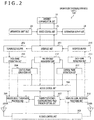
- FIG. 2 is a block diagram illustrating a functional configuration example of the information processing apparatus (AP1) 100 according to the embodiment of the present technique.
- FIG. 2 illustrates only the functional configuration example of the information processing apparatus (AP1) 100 for the convenience, the functional configurations (functional configurations related to wireless communication) of the other information processing apparatuses (AP, STA) are also similar.
- the information processing apparatus (AP) as the access point and the other information processing apparatuses (STA) have the same configuration for the convenience, part of the configuration may be different according to the devices.
- an Internet communication unit 21 may be connected to the Internet through a wired network.
- a device control unit 23 may control the configurations.
- the information processing apparatus (AP1) 100 includes the Internet communication unit 21, an information input unit 22, the device control unit 23, and an information output unit 24.
- Each of the components is an example of the system configuration in the information processing apparatus (AP1) 100 and may be provided as necessary. In addition, part or all of the functions of the components may provide a wireless communication system.
- the information processing apparatus (AP1) 100 may operate as a wireless communication device or a wireless communication module excluding the components.
- the Internet communication unit 21 is a communication unit for connection to the Internet.
- the information input unit 22 is an information input unit that receives input of information (for example, keyboard input) from the user and that acquires various types of information (for example, image information and sound information).
- the information output unit 24 is an information output unit that outputs information to the user (for example, indication of an image and video on a display and audio output of sound information and music information).
- the device control unit 23 is configured to control the entire system in the information processing apparatus (AP1) 100.
- the information processing apparatus (AP1) 100 further includes an interface unit 201, a transmission buffer 202, a data frame generation unit 203, a control frame generation unit 204, a wireless signal transmission processing unit 205, an access control unit 206, a transmission power control/received field strength setting unit 207, an antenna control unit 208, antenna elements 209A and 209B, a wireless signal reception processing unit 210, a control frame extraction unit 211, an NAV and ONAV management unit 212, a data frame extraction unit 213, and a reception buffer 214.
- Each of the components is realized by, for example, a wireless communication module specialized for wireless communication.
- the interface unit 201 is an interface that receives application data on the basis of input of information from the user and that outputs application data.
- the interface unit 201 receives wirelessly transmitted application data from the device control unit 23 on the basis of the input of information from the user and causes the transmission buffer 202 to hold the application data.
- the interface unit 201 outputs, to the device control unit 23, wirelessly received application data as information for the user.
- the transmission buffer 202 is a transmission buffer that temporarily holds data to be transmitted from the information processing apparatus (AP1) 100 to another information processing apparatus.
- the transmission buffer 202 then supplies the held data to the data frame generation unit 203.
- the data frame generation unit 203 is configured to construct the data (transmission data) held in the transmission buffer 202 into a predetermined data frame format for wireless transmission. The data frame generation unit 203 then outputs the generated data frame to the wireless signal transmission processing unit 205.
- the control frame generation unit 204 is configured to construct control frames, such as an RST frame, a CTS frame, and an ACK frame, according to data transmission on the basis of an instruction from the NAV and ONAV management unit 212.
- the control frame generation unit 204 then outputs the generated control frame to the wireless signal transmission processing unit 205.
- the wireless signal transmission processing unit 205 is configured to convert a transmitted data frame into a high-frequency signal as a baseband signal. The wireless signal transmission processing unit 205 then outputs the baseband signal converted into the high-frequency signal to the antenna control unit 208 on the basis of control of the access control unit 206.
- the access control unit 206 is an access control unit that controls access in communication on a wireless transmission path in compliance with a predetermined wireless communication protocol.
- the access control unit 206 can control the access in the communication on the wireless transmission path on the basis of details of management by the NAV and ONAV management unit 212. For example, while all the NAV and the ONAVs of the OBSSs as management targets of the NAV and ONAV management unit 212 are cancelled, the access control unit 206 performs control for transmitting a signal to the wireless transmission path. Furthermore, for example, the access control unit 206 can perform control not to transmit a signal to the wireless transmission path until all the NAV and the ONAVs of the OBSSs as management targets of the NAV and ONAV management unit 212 are cancelled.
- the transmission power control/received field strength setting unit 207 is a transmission power control/received field strength setting unit that sets desired transmission power and signal detection level of received field strength.
- the antenna control unit 208 is an antenna control unit that controls an antenna for transmitting a signal to the wireless transmission path and receiving a signal from the wireless transmission path.
- the antenna elements 209A and 209B are antenna elements as a plurality of antenna elements that transmit or receive signals.
- the wireless signal reception processing unit 210 is configured to extract a baseband signal from a high-frequency signal received through the antenna. The wireless signal reception processing unit 210 then outputs the extracted baseband signal to the access control unit 206, the control frame extraction unit 211, and the data frame extraction unit 213.
- the control frame extraction unit 211 is configured to extract, from the baseband signal, predetermined control frames, such as an RTS frame, a CTS frame, and a ACK frame, indicating the situation of usage of the transmission path.
- the control frame extraction unit 211 then outputs the extracted control frames to the access control unit 206 and the NAV and ONAV management unit 212.
- the NAV and ONAV management unit 212 is configured to manage the NAV set in the BSS including the apparatus and manage, for each OBSS, the ONAVs set in the OBSSs.
- the NAV and ONAV management unit 212 can set the NAV on the basis of the control signal (control frame) received from another information processing apparatus belonging to the BSS of the apparatus.
- the NAV and ONAV management unit 212 can set the ONAV of each OBSS on the basis of the control signal (control frame) received from another information processing apparatus belonging to the OBSS.
- the NAV and ONAV management unit 212 can manage, for each of a plurality of OBSSs, the ONAVs set in the plurality of OBSSs.
- NAV and ONAV management unit 212 is an example of a management unit described in the claims.
- the data frame extraction unit 213 is configured to extract data included in the data frame from the baseband signal. The data frame extraction unit 213 then causes the reception buffer 214 to hold the extracted data.
- the reception buffer 214 is a reception buffer that temporarily holds received data and the like until data in predetermined units is collected. The reception buffer 214 then supplies the held data to the interface unit 201.
- FIG. 3 depicts a configuration example of a frame format exchanged between devices as a basis of the present technique.
- FIG. 3 a illustrates a configuration example of an RTS (Request to Send) frame.
- the RTS frame includes Frame Control 301, Duration 302, RA (Receive Address) 303, TA (Transmit Address) 304, and FCS (Frame Check Sequence) 305.
- Duration information for setting the NAV is stored in the Duration 302.
- a reception side address is designated in the RA 303.
- a transmission side address is designated in the TA 304.
- address information for example, MAC (Media Access Control) address
- MAC Media Access Control
- FCS 305 Information for error detection is stored in the FCS 305.
- FIG. 3 b illustrates a configuration example of a CTS (Clear to Send) frame.
- the CTS frame includes Frame Control 311, Duration 312, RA 313, and FCS 314.
- Duration information for designating the format of the CTS frame is stored in the Frame Control 311. Duration information for setting the NAV is stored in the Duration 312.
- a target address is designated in the RA 313.
- address information of the information processing apparatus (STA) is stored in the RA 313. That is, a copy of the TA 304 illustrated in a of FIG. 3
- c illustrates a configuration example of an ACK (Acknowledgement) frame.
- the ACK frame includes Frame Control 321, Duration 322, RA 323, and FCS 324.
- Duration Information for designating the format of the ACK frame is stored in Frame Control 321.
- Duration information for setting the NAV is stored in the Duration 322.
- a target address is designated in the RA 323.
- Information for error detection is stored in the FCS 324.
- d illustrates a configuration example of a PS-Poll (Power Save Polling) frame.
- the PS-Poll frame includes Frame Control 331, AID (Association Identifier) 332, BSSID (RA) 333, TA 334, and FCS 335.
- Information for designating the format of the PS-Poll frame is stored in the Frame Control 331.
- Information related to an association identifier is stored in the AID 332.
- BSSID information is designated as a reception side address in the BSSID (RA) 333.
- a transmission side address is designated in the TA 334.
- Information for error detection is stored in the FCS 335.
- e illustrates a configuration example of a CF-END (Contention Free End) frame.
- the CF-END frame includes Frame Control 341, Duration 342, RA 343, BSSID (TA) 344, and FCS 345.
- Duration Information for designating the format of the CF-END frame is stored in the Frame Control 341.
- Duration information for setting the NAV is stored in the Duration 342.
- a reception side address is designated in the RA 343.
- BSSID information is designated as a transmission side address in the BSSID (TA) 344.
- Information for error detection is stored in the FCS 345.
- f illustrates a configuration example of a CF-END + CF-ACK (Contention Free End + Contention Free Ack) frame.
- the CF-END + CF-ACK frame includes Frame Control 351, Duration 352, RA 353, BSSID (TA) 354, and FCS 355.
- Duration Information for designating the format of the CF-END + CF-ACK frame is stored in the Frame Control 351.
- Duration information for setting the NAV is stored in the Duration 352.
- a reception side address is designated in the RA 353.
- BSSID information is designated as a transmission side address in the BSSID (TA) 354.
- Information for error detection is stored in the FCS 355.
- FIG. 4 depicts an example of setting and cancelling an NAV as a basis of the present technique.
- the horizontal axis illustrated in FIG. 4 indicates a time axis.
- data to be transmitted is indicated by rectangles provided with content inside.
- a illustrates an example of a case of setting the NAV by exchanging an RTS frame and a CTS frame.
- a illustrates an example of communication between a device on the transmission side of data (transmission side device) and a device on the reception side of data (reception side device) and an example of setting the NAV.
- the transmission side device transmits an RTS frame to the reception side device before transmitting the data to the reception side device (401).
- a time period (transmission suppression time period) of setting the NAV is stored in the Duration 302 (illustrated in a of FIG. 3 ) in the RTS frame.
- the transmission side device further sets the NAV on the basis of the virtual carrier sense throughout the time period stored in the Duration 302 (illustrated in a of FIG. 3 ) in the RTS frame (405).
- the reception side device transmits a CTS frame for the RTS frame to the transmission side device (402).
- a time period (transmission suppression time period) of setting the NAV is stored in the Duration 312 (illustrated in b of FIG. 3 ) in the CTS frame.
- the reception side device further sets the NAV on the basis of the virtual carrier sense throughout the time period stored in the Duration 312 (illustrated in b of FIG. 3 ) in the CTS frame (406). Note that end timing of the NAV set in the transmission side device and end timing of the NAV set in the reception side device are the same.
- the transmission side device transmits data (Data) to the reception side device (403).
- an acknowledgement (Ack) is exchanged as necessary (404).
- b illustrates an example of a case of setting the NAV on the basis of CTS-to-self.
- b illustrates an example of communication between a device on the transmission side of data (transmission side device) and a device on the reception side of data (reception side device) and an example of setting and cancelling the NAV.
- the transmission side device transmits a CTS-to-self frame to the reception side device before transmitting data to the reception side device (411).
- a time period (transmission suppression time period) of setting the NAV is stored in the Duration 312 (illustrated in b of FIG. 3 ) in the CTS-to-self frame. In this case, a maximum value is stored as the transmission suppression time period.
- the transmission side device and the reception side device further set the NAV as a CF (Contention Free) region throughout the time period stored in the Duration 312 (illustrated in b of FIG. 3 ) in the CTS-to-self frame (415).
- the transmission side device transmits data (Data) to the reception side device (412).
- An acknowledgement (Ack) is also exchanged as necessary (413) .
- the transmission side device transmits a CF-END frame to the reception side device to inform that the CF period is finished (414). In this way, the transmission side device can transmit the CF-END frame to the reception side device to cancel the previously set NAV as a CF region (416).
- c illustrates an example of a case of setting the NAV on the basis of CTS-to-self.
- c illustrates an example of communication between a device on the setting side of setting the NAV (setting side device) and a target device of the device (target side device) and an example of setting and cancelling the NAV. Note that the example illustrated in c of FIG. 4 is a modification of b of FIG. 4 , and the description of the part in common with b of FIG. 4 will not be repeated.
- the setting side device transmits a CTS-to-self frame to the target side device (421).
- the setting side device and the target side device further set the NAV as a CF region throughout the time period stored in the Duration 312 (illustrated in b of FIG. 3 ) in the CTS-to-self frame (425).
- the setting side device transmits data (Data + Poll) to the target side device (422). After the data transmission, the setting side device also receives data and an acknowledgement (Data + Ack) from the target side device designated by Poll (423).
- the setting side device transmits a frame for informing that the CF period is finished to the target side device (424). That is, the setting side device transmits a frame including an acknowledgement and CF-END (Ack + CFend) to the target side device (424). In this way, the setting side device can transmit the CF-END frame to the target side device to cancel the previously set NAV as a CF region (426).
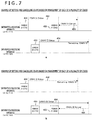
- FIG. 5 depicts an example of setting and cancelling the ONAV as a basis of the present technique.
- the horizontal axis illustrated in FIG. 5 indicates a time axis.
- FIG. 5 also illustrates two devices (OBSS AP2, OBSS AP3) as devices belonging to the OBSSs.
- OBSS AP2, OBSS AP3 As devices belonging to the OBSSs.
- data to be transmitted from each device is indicated by rectangles provided with content inside.
- FIG. 5 illustrates a comparative example of FIG. 7 .
- a and b illustrate examples of a case of setting and cancelling one ONAV for a plurality of OBSSs.
- a and b illustrate examples of managing a longest time period (time period stored in Duration) as the ONAV of the OBSSs in a case where signals are received from a plurality of OBSSs.
- FIG. 5 a illustrates an example of a case of receiving a CF-END frame from the OBSS AP2.
- an information processing apparatus (STA) 1 (not illustrated) receives a CTS frame (OBSS A CTS) from the OBSS AP2 (431), the information processing apparatus (STA) 1 sets the ONAV on the basis of the value stored in the Duration in the CTS frame (432).
- the information processing apparatus (STA) 1 receives a CTS frame (OBSS B CTS) from the OBSS AP3 after setting the ONAV (433)
- the information processing apparatus (STA) 1 updates the ONAV on the basis of the value stored in the Duration in the CTS frame (434).
- the example illustrated in a of FIG. 5 illustrates an example of a case where the ONAV is extended by the update of the ONAV.
- the information processing apparatus (STA) 1 receives a CF-END frame from the OBSS AP2 after updating the ONAV (435), the information processing apparatus (STA) 1 cancels the updated ONAV (436).
- the information processing apparatus (STA) 1 cancels the updated ONAV on the basis of the CF-END frame from the OBSS AP2.
- the information processing apparatus (STA) 1 may not be able to figure out that the OBSS AP3 is using the wireless transmission path and may start data transmission of the apparatus. In this way, there may be a collision between the information processing apparatus (STA) 1 and the OBSS AP3 in the case where the data transmission from the information processing apparatus (STA) 1 is started.
- FIG. 5 b illustrates an example of a case of receiving a CF-END frame from the OBSS AP3.
- the information processing apparatus (STA) 1 sets the ONAV in response to the reception of the CTS frame from the OBSS AP2 and updates the ONAV in response to the reception of the CTS frame from the OBSS AP3 (441 to 444), and this is similar to the example illustrated in a of FIG. 5 .
- the information processing apparatus (STA) 1 receives a CF-END frame from the OBSS AP3 after updating the ONAV (445), the information processing apparatus (STA) 1 cancels the updated ONAV (446).
- the information processing apparatus (STA) 1 cancels the updated ONAV on the basis of the CF-END frame from the OBSS AP3.
- the information processing apparatus (STA) 1 may not be able to figure out that the OBSS AP2 is using the wireless transmission path and may start data transmission of the apparatus. In this way, there may be a collision between the information processing apparatus (STA) 1 and the OBSS AP2 in the case where the data transmission from the information processing apparatus (STA) 1 is started.
- the embodiment of the present technique illustrates an example of individually managing the NAV (ONAV) for each of the plurality of OBSSs to allow appropriate wireless communication even in an environment including a plurality of OBSSs.
- NAV NAV
- the NAV of the BSS including the target device will be referred to as NAV.
- the NAV of another BSS (OBSS) that is a BSS other than the BSS including the target device and that transmits a radio wave reaching the target device will be referred to as ONAV.
- FIG. 6 depicts an example of managing the NAV and the ONAVs by the NAV and ONAV management unit 212 according to the embodiment of the present technique.
- FIG. 6 a illustrates an example of an ONAV information management table used to manage the ONAV for each of a plurality of OBSSs.
- frame type 501 In the ONAV information management table, frame type 501, RA 502, TA 503, reception time 504, Duration 505, provisional registration 506, and reception signal strength 507 are associated and recorded.
- the type of the frame received by the information processing apparatus (AP1) 100 from a device belonging to the OBSS is stored in the frame type 501.
- the types of the frames illustrated in a to f of FIG. 3 are stored.
- the RA stored in the frame received by the information processing apparatus (AP1) 100 from the device belonging to the OBSS is stored in the RA 502.
- the information of the RAs 303, 313, 323, 333, 343, and 353 illustrated in a to f of FIG. 3 is stored.
- the TA stored in the frame received by the information processing apparatus (AP1) 100 from the device belonging to the OBSS is stored in the TA 503.
- the information of the TAs 304, 334, 344, and 354 illustrated in a and d to f of FIG. 3 is stored.
- the time of the reception (or reception timing) of the frame by the information processing apparatus (AP1) 100 from the device belonging to the OBSS is stored in the reception time 504.
- the value of the Duration stored in the frame received by the information processing apparatus (AP1) 100 from the device belonging to the OBSS is stored in the Duration 505.
- the information of the Duration 302, 312, 322, 342, and 352 illustrated in a to c, e, and f of FIG. 3 is stored.
- Information indicating one of definitive registration and provisional registration is stored in the provisional registration 506. For example, "0" is stored in the provisional registration 506 in the case of the definitive registration, and "1" is stored in the case of the provisional registration. Note that the definitive registration and the provisional registration will be described in detail with reference to FIG. 8 .
- the reception signal strength of the frame at the reception of the frame by the information processing apparatus (AP1) 100 from the device belonging to the OBSS is stored in the reception signal strength 507.
- An example of the reception signal strength that can be used includes RSSI (Received Signal Strength Indicator).
- Other radio wave condition information may also be stored instead of the reception signal strength.
- PER Packet Error Rate
- BER Bit Error Rate
- SINR Signal to Interference plus Noise Ratio
- FIG. 6 b illustrates an example of an NAV information management table used to manage the NAV of the BSS including the information processing apparatus (AP1) 100.
- AP1 information processing apparatus
- reception time 511 and Duration 512 are associated and recorded.
- the time of the reception (or reception timing) of the frame by the information processing apparatus (AP1) 100 from the device belonging to the BSS of the apparatus is stored in the reception time 511.
- the value of the Duration stored in the frame received by the information processing apparatus (AP1) 100 from the device belonging to the BSS of the apparatus is stored in the Duration 512.
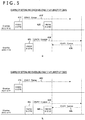
- FIG. 7 depicts an example of managing the ONAV by the NAV and ONAV management unit 212 according to the embodiment of the present technique.
- FIG. 7 illustrates an example of managing the ONAV by the information processing apparatus (AP1, STA1-1, or STA1-2) for each of a plurality of OBSSs (information processing apparatus of first OBSS (AP2, STA2-1, or STA2-2) and information processing apparatus of second OBSS (AP3, STA3-1, or STA3-2)) in the example illustrated in FIG. 1 .
- the NAV and ONAV management unit 212 included in the information processing apparatus 100 manages the ONAV for each of a plurality of OBSSs and sets and cancels the ONAV for each of a plurality of OBSSs in the illustrated example.
- the horizontal axis illustrated in FIG. 7 indicates the time axis. Furthermore, above the time axis corresponding to each device, data to be transmitted from each device is indicated by rectangles provided with content inside.
- FIG. 7 a illustrates an example of a case where the information processing apparatus (AP1) 100 receives a CF-END frame from the information processing apparatus (AP2) 110.
- the NAV and ONAV management unit 212 sets an ONAV (ONAV A) of the information processing apparatus (AP2) 110 on the basis of the CTS frame (452).
- the NAV and ONAV management unit 212 records each piece of information in the ONAV information management table illustrated in a of FIG. 6 on the basis of the CTS frame. Specifically, the NAV and ONAV management unit 212 records "CTS" in the frame type 501 and records the information of the RA 313 of the CTS frame (illustrated in b of FIG. 3 ) in the RA 520. The NAV and ONAV management unit 212 further records the time of the reception of the CTS frame in the reception time 504 and records the value of the Duration 312 of the CTS frame (illustrated in b of FIG. 3 ) in the Duration 505.
- CTS CTS
- the NAV and ONAV management unit 212 further records the time of the reception of the CTS frame in the reception time 504 and records the value of the Duration 312 of the CTS frame (illustrated in b of FIG. 3 ) in the Duration 505.
- the NAV and ONAV management unit 212 also records "0" in the provisional registration 506 and records the RSSI at the reception of the CTS frame in the reception signal strength 507. In this way, on the basis of the received CTS frame, the NAV and ONAV management unit 212 sets the ONAV (ONAV A) of the OBSS (information processing apparatus (AP2) 110) that has transmitted the CTS frame. In addition, in a case where the RTS frame is received just before the CTS frame, and it is recognized that the CTS frame is for the RTS frame, the CTS frame is managed along with the ONAV (ONAV A) of the OBSS (information processing apparatus (AP2) 110) that has transmitted the RTS frame to manage one ONAV for one OBSS.
- the information processing apparatus (AP1) 100 receives a CTS frame (OBSS B CTS) from the information processing apparatus (AP3) 120 after setting the ONAV A will be illustrated (453).
- the NAV and ONAV management unit 212 sets an ONAV (ONAV B) of the OBSS (information processing apparatus (AP3) 120) on the basis of the CTS frame (454).
- the setting method is similar to the setting method of the ONAV A of the information processing apparatus (AP2) 110, and the description will not be repeated here.
- the NAV and ONAV management unit 212 sets and manages the ONAV for each of a plurality of OBSSs (information processing apparatus (AP2) 110 and information processing apparatus (AP3) 120).
- a case where the information processing apparatus (AP1) 100 receives a CF-END frame from the information processing apparatus (AP2) 110 after setting the ONAV A and the ONAV B will be illustrated (455).
- the NAV and ONAV management unit 212 cancels the ONAV A of the information processing apparatus (AP2) 110 on the basis of the CF-END frame (456).
- the NAV and ONAV management unit 212 deletes, from the ONAV information management table illustrated in a of FIG. 6 , each piece of information corresponding to the ONAV A of the information processing apparatus (AP2) 110 that has transmitted the CF-END frame.
- the NAV and ONAV management unit 212 determines whether or not the BSSID (TA) 344 of the CF-END frame (illustrated in e of FIG. 3 ) coincides with the BSSID of the BSS including the apparatus. Then, in a case where the BSSID (TA) 344 of the CF-END frame is different from the BSSID of the BSS including the apparatus, the NAV and ONAV management unit 212 can figure out that the CF-END frame is transmitted from the OBSS. In this case, the NAV and ONAV management unit 212 extracts the RA coinciding with the RA 343 of the CF-END frame (illustrated in e of FIG.
- the NAV and ONAV management unit 212 then deletes each piece of information associated with the coinciding RA 502 (each piece of information corresponding to the ONAV A of the information processing apparatus (AP2) 110) from the ONAV information management table.
- a broadcast address is written in the RA 343 of the CF-END frame in the RA 502 of the ONAV information management table, and in a case where there is no frame coinciding with the RTS frame or the CTS frame, there is a possibility that the CF-END frame is transmitted from an OBSS not registered in the ONAV information management table. Therefore, the NAV and ONAV management unit 212 ignores the CF-END frame in this case and does not execute the process of deletion from the ONAV information management table.
- the information processing apparatus (AP1) 100 can figure out that the information processing apparatus (AP3) 120 is using the wireless transmission path in the period of the ONAV B of the information processing apparatus (AP3) 120 and can prevent the start of the data transmission of the apparatus. This can prevent a collision between the information processing apparatus (AP1) 100 and the information processing apparatus (AP3) 120.
- FIG. 7 b illustrates an example of a case where the information processing apparatus (AP1) 100 receives a CF-END frame from the information processing apparatus (AP3) 120.
- the information processing apparatus (AP1) 100 sets the ONAV A in response to the reception of the CTS frame from the information processing apparatus (AP2) 110 and sets the ONAV B in response to the reception of the CTS frame from the information processing apparatus (AP3) 120 (461 to 464), and this is similar to the example illustrated in a of FIG. 7 .
- the NAV and ONAV management unit 212 deletes, from the ONAV information management table illustrated in a of FIG. 6 , each piece of information corresponding to the ONAV B of the information processing apparatus (AP3) 120 that has transmitted the CF-END frame. Note that the deletion method is similar to the example illustrated in a of FIG. 7 , and the description will not be repeated here.
- the information processing apparatus (AP1) 100 can figure out that the information processing apparatus (AP2) 110 is using the wireless transmission path in the period of the ONAV A of the information processing apparatus (AP2) 110 and can prevent the start of the data transmission of the apparatus. This can prevent a collision between the information processing apparatus (AP1) 100 and the information processing apparatus (AP2) 110.
- the ONAV is individually managed for each of a plurality of OBSSs in the embodiment of the present technique, and this allows appropriate wireless communication even in the environment including a plurality of OBSSs.
- FIG. 7 illustrates an example in which the NAV and ONAV management unit 212 manages the ONAVs for two OBSSs
- the NAV and ONAV management unit 212 can similarly manage the ONAVs for three or more OBSSs.
- OBSSs there may be a case where there are a large number of OBSSs as management targets of the NAV and ONAV management unit 212.
- only a predetermined number of OBSSs may be set as the management targets based on a predetermined rule. For example, on the basis of the reception time 504 and the Duration 505 of the ONAV information management table illustrated in a of FIG. 6 , a predetermined number of OBSSs can be sequentially selected as the management targets from the OBSS with the latest cancel timing of ONAV.
- a predetermined number of OBSSs can be sequentially selected as the management targets from the OBSS with the best value of RSSI.
- FIG. 8 is a flow chart illustrating a processing procedure of an NV and ONAV management process by the information processing apparatus according to the embodiment of the present technique. To facilitate the description, the components illustrated in FIG. 2 will be used in the description of FIG. 8 .
- control frame extraction unit 211 extracts each piece of information (for example, Duration and address information) from the received RTS frame or CTS frame (step S802).
- the NAV and ONAV management unit 212 determines whether or not the RTS frame or the CTS frame is from another information processing apparatus (STA) belonging to the BSS of the apparatus on the basis of the extracted information (address information) (step S803). Then, if the RTS frame or the CTS frame is from another information processing apparatus (STA) belonging to the BSS of the apparatus (step S803), the NAV and ONAV management unit 212 sets the NAV on the basis of the extracted Duration (step S804). For example, the NAV and ONAV management unit 212 records the reception time of the RTS frame or the CTS frame in the reception time 511 and records the value of the extracted Duration in the Duration 512 in the NAV information management table illustrated in b of FIG. 6 .
- the NAV and ONAV management unit 212 determines whether or not the frame is a CTS-to-self frame from another information processing apparatus (AP) belonging to the BSS of the apparatus (step S805).
- the NAV and ONAV management unit 212 recognizes that a CF region is started (step S806). That is, the NAV and ONAV management unit 212 recognizes that a CF (Contention Free) region is set throughout the time period described in the extracted Duration (step S806).
- the NAV and ONAV management unit 212 can figure out that the data is to be transmitted in the BSS.
- the NAV and ONAV management unit 212 determines whether or not the frame is a CTS frame from an information processing apparatus (STA) of an OBSS (step S807). If the frame is a CTS frame from an information processing apparatus (STA) of an OBSS (step S807), the NAV and ONAV management unit 212 sets the ONAV on the basis of the received CTS frame (step S808). The NAV and ONAV management unit 212 records each piece of information (for example, RA and Duration) related to the received CTS frame and records "0" in the provisional registration 505 in the ONAV information management table illustrated in a of FIG. 6 .
- RA and Duration for example, RA and Duration
- the NAV and ONAV management unit 212 can set the ONAV of the OBSS as a management target.
- the NAV and ONAV management unit 212 provisionally sets (provisionally registers) the ONAV on the basis of the received RTS frame (step S809).
- the NAV and ONAV management unit 212 records each piece of information (for example, RA, TA, and Duration) related to the received RTS frame and records "1" in the provisional registration 505 in the ONAV information management table illustrated in a of FIG. 6 .
- the value of the Duration can be provisionally set (provisionally registered) as an ONAV value.
- the provisionally set (provisionally registered) ONAV is definitively registered in a case where a predetermined condition is satisfied.
- the ONAV can be definitively registered.
- control such as lowering the packet detection threshold from a normal threshold, may be performed to facilitate the reception of the CTS frame.
- the ONAV may be set on a condition that the CTS frame (corresponding to the RTS frame) from the OBSS is received just after the reception of the RTS frame from the information processing apparatus (STA) of the OBSS.
- step S810 determines whether or not a data frame is received. Then, if a data frame is received (step S810), the data frame extraction unit 213 extracts a data part of the received data frame (step S811). Subsequently, whether or not an ACK corresponding to the received data frame needs to be returned is determined (step S812). Then, if an ACK needs to be returned (step S812), the ACK is returned (step S813). For example, the ACK is returned in a case where the data frame is correctly received on the basis of designation of an Ack Policy bit of the received data frame (step S813). Note that if an ACK does not have to be returned (step S812), the process returns to step S801.
- step S810 If a data frame is not received (step S810), whether or not a CF-END frame is received is determined (step S814). Then, if a CF-END frame is received (step S814), the control frame extraction unit 211 extracts each piece of information (for example, Duration and address information) from the received CF-END frame (step S815).
- each piece of information for example, Duration and address information
- the NAV and ONAV management unit 212 determines whether or not the CF-END frame is from the information processing apparatus (AP) belonging to the BSS of the apparatus on the basis of the extracted information (BSSID (TA)) (step S816). For example, in a case where the extracted BSSID (TA) is the address (BSSID) of the information processing apparatus (AP) belonging to the BSS of the apparatus, the NAV and ONAV management unit 212 determines that the CF-END frame is from the information processing apparatus (AP) belonging to the BSS of the apparatus (step S816). Then, if the CF-END frame is from the information processing apparatus (AP) belonging to the BSS of the apparatus (step S816), the NAV and ONAV management unit 212 recognizes that the CF region is finished (step S817).
- the extracted BSSID (TA) is the address (BSSID) of the information processing apparatus (AP) belonging to the BSS of the apparatus
- the NAV and ONAV management unit 212 determines that the CF-
- the NAV and ONAV management unit 212 can figure out that the CF region is finished in the BSS and that the data is not transmitted from the access point (AP) of the BSS.
- the NAV and ONAV management unit 212 determines whether or not an ONAV corresponding to the extracted BSSID (TA) is set (step S818). For example, the NAV and ONAV management unit 212 determines whether or not there is a TA coinciding with the extracted BSSID (TA) in the TA 503 illustrated in a of FIG. 6 . Then, if there is a TA coinciding with the extracted BSSID (TA) in the TA 503 illustrated in a of FIG.
- the NAV and ONAV management unit 212 determines that the ONAV corresponding to the extracted BSSID (TA) is set (step S818). On the other hand, if there is no TA coinciding with the extracted BSSID (TA) in the TA 503 illustrated in a of FIG. 6 , the NAV and ONAV management unit 212 determines that the ONAV corresponding to the extracted BSSID (TA) is not set (step S818).
- step S820 If the ONAV corresponding to the extracted BSSID (TA) is not set (step S818), the process proceeds to step S821. Furthermore, if the ONAV corresponding to the extracted BSSID (TA) is set (step S818), the NAV and ONAV management unit 212 cancels the ONAV corresponding to the extracted BSSID (TA) (step S820).
- the NAV and ONAV management unit 212 can cancel the ONAV of the OBSS corresponding to the address information in the CF-END frame.
- the NAV and ONAV management unit 212 determines whether or not there is a timed-out NAV or ONAV among the set NAV and ONAVs (step S819). For example, the NAV and ONAV management unit 212 can extract the timed-out ONAV on the basis of the reception time 504 and the Duration 505 illustrated in a of FIG. 6 (step S819). Furthermore, the NAV and ONAV management unit 212 can determine whether or not the NAV is timed out on the basis of, for example, the reception time 511 and the Duration 512 illustrated in b of FIG. 6 (step S819).
- step S820 If there is a timed-out NAV or ONAV among the set NAV and ONAVs (step S819), the NAV and ONAV management unit 212 cancels the timed-out NAV or ONAV (step S820).
- the apparatus repeats the series of operations (steps S801 to S821) after the end of the CF region in the BSS of the apparatus, until there is an instruction for ending the communication in the contention region for a predetermined time period (step S821), for example.
- steps S801 to S820 are an example of a control procedure described in the claims.
- the NAV and ONAV management unit 212 can manage, for each OBSS, the ONAV (transmission suppression time period) set in the OBSS that transmits a radio wave reaching at least the apparatus, along with the NAV (transmission suppression time period) set in the BSS.
- the NAV and ONAV management unit 212 can set the NAV for each OBSS on the basis of a control signal received from another information processing apparatus belonging to the OBSS.
- the NAV and ONAV management unit 212 can set the ONAV of the OBSS on the basis of the value of the Duration in the control signal received from another information processing apparatus belonging to the OBSS.
- the NAV and ONAV management unit 212 can also change the details of management of the ONAV on the basis of the type of the control signal received from another information processing apparatus belonging to the OBSS.
- the information processing apparatus (AP1) 100 can also transmit data from the apparatus in a case where neither the NAV nor the ONAV is set. That is, the access control unit 206 can transmit data from the apparatus in a case where there is no registration in the ONAV information management table illustrated in a of FIG. 6 and there is no registration in the NAV information management table illustrated in b of FIG. 6 . On the other hand, the access control unit 206 performs control not to transmit a signal to the wireless transmission path until all the registration in the ONAV information management table illustrated in a of FIG. 6 and the registration in the NAV information management table illustrated in b of FIG. 6 are cancelled.
- the ONAVs of individual OBSSs can be set and managed for each OBSS on the basis of control signals from the plurality of OBSSs existing around the BSS including the apparatus.
- the situation of the ONAV set for each OBSS can be figured out.
- a signal for cancelling an ONAV of an OBSS is received, only the ONAV of the OBSS that has transmitted the signal can be cancelled, and the other ONAVs of the OBSS can be maintained and figured out. That is, the other ONAVs can be maintained even in the case where one ONAV is cancelled, and the virtual carrier sense from different OBSSs can be surely carried out.
- This can realize an operation that avoids a collision with communication of surrounding OBSSs. In other words, a mechanism for preventing an unintended collision of frames in advance can be provided.
- the number of ONAVs of OBSSs to be managed can be controlled according to the capacity of the information processing apparatus. That is, instead of managing the ONAVs of OBSSs without a limitation, only two or more longest ONAVs may be managed according to the capacity of the information processing apparatus. As a result, communication control for more surely avoiding a collision with communication of OBSSs can be realized in a more advanced device.
- the ONAVs of the OBSSs can be recorded according to the formats of the frames. As a result, essentially necessary ONAVs for the OBSSs can be appropriately managed.
- the individual NAVs (ONAVs) that are once set are not cancelled unless a CF-END frame is received from the information processing apparatus that has set the NAV (ONAV).
- the control for preventing a collision with signal reception of OBSSs can be appropriately performed.
- a CTS frame is received from an information processing apparatus (AP) of the BSS including the apparatus, it can be determined that the CF region is started when the CTS frame is a CTS-to-self frame. This allows to figure out that the data is to be transmitted to the apparatus after the reception of the CTS frame.
- AP information processing apparatus
- a CF-END frame is received from an information processing apparatus (AP) of the BSS including the apparatus, it can be determined that the CF region is finished. This allows to figure out that the data is not to be transmitted to the apparatus after the reception of the CF-END frame.
- AP information processing apparatus
- provisional setting can be performed instead of setting the ONAV of the OBSS.
- the ONAV is set on a condition that the CTS frame is received from the information processing apparatus (AP) included in the OBSS. That is, the ONAV from the information processing apparatus (AP) included in the OBSS is validated, and the ONAV can be managed on the basis of the type of frame. This can increase transmission opportunities without affecting other devices.
- FIG. 1 illustrates an example of a communication system including three BSSs (nine devices), the number of BSSs and the number of devices are not limited to these.
- the connection mode of a plurality of devices is not limited to the connection modes described above.
- the embodiment of the present technique can also be applied to a network connecting a plurality of devices based on a connection mode other than the connection modes described above.
- the communication system includes an access point (master station) and subordinate apparatuses (slave stations) of the access point.
- the embodiment of the present technique may be applied to, for example, a network in which a plurality of devices wirelessly communicate one-to-one, and the plurality of devices are connected to each other (for example, mesh network or ad hoc network).
- the embodiment of the present technique can be applied to a mesh network of IEEE 802.11s.
- the NAV in the BSS including the apparatus is not managed. Then, whether the series of setting and cancelling the NAV are necessary can be determined in response to reception of a control frame, such as an RTS frame and a CTS frame, transmitted from a device around the apparatus.
- a control frame such as an RTS frame and a CTS frame
- the embodiment of the present technique can also be applied to wireless communication between in-vehicle devices (for example, vehicle-to-vehicle communication or road-to-vehicle communication (V2X (vehicle to X))).
- in-vehicle devices for example, vehicle-to-vehicle communication or road-to-vehicle communication (V2X (vehicle to X)
- V2X vehicle to X
- information of the distance measured between another device and the apparatus or the like may also be managed in addition to the information of the received field strength, for example.
- the information processing apparatuses can be applied to devices used in each field.
- the information processing apparatuses can be applied to wireless devices used in cars (for example, car navigation apparatuses and smartphones).
- the information processing apparatuses can also be applied to, for example, the vehicle-to-vehicle communication or the road-to-vehicle communication (V2X) as described above.
- the information processing apparatuses can also be applied to, for example, learning devices used in the educational field (for example, tablet terminals).
- the information processing apparatuses can also be applied to, for example, wireless devices used in the agricultural field (for example, terminals of cattle management system).
- the information processing apparatuses can be applied to, for example, wireless devices used in the sports field, the medical field, and the like.
- the information processing apparatus may be realized as a mobile terminal, such as a smartphone, a tablet PC (Personal Computer), a notebook PC, a mobile game terminal, and a digital camera, a fixed terminal, such as a television receiver, a printer, a digital scanner, and a network storage, or an in-vehicle terminal, such as a car navigation apparatus.
- a mobile terminal such as a smartphone, a tablet PC (Personal Computer), a notebook PC, a mobile game terminal, and a digital camera
- a fixed terminal such as a television receiver, a printer, a digital scanner, and a network storage
- an in-vehicle terminal such as a car navigation apparatus.
- the information processing apparatus may also be realized as a terminal (also called MTC (Machine Type Communication) terminal) that performs M2M (Machine To Machine) communication, such as a smart meter, a vending machine, a remote monitoring apparatus, and a POS (Point Of Sale) terminal.
- the information processing apparatus may also be a wireless communication module mounted on these terminals (for example, integrated circuit module including one die).
- the information processing apparatus may be realized as, for example, a wireless LAN access point (also called wireless base station) with a router function or without a router function.
- the information processing apparatus (AP) may also be realized as a mobile wireless LAN router.
- the information processing apparatus (AP) may also be a wireless communication module mounted on these apparatuses (for example, integrated circuit module including one die).
- FIG. 9 is a block diagram illustrating an example of a schematic configuration of a smartphone 900 to which the technique according to the present disclosure can be applied.
- the smartphone 900 includes a processor 901, a memory 902, a storage 903, an external connection interface 904, a camera 906, a sensor 907, a microphone 908, an input device 909, a display device 910, a speaker 911, a wireless communication interface 913, an antenna switch 914, an antenna 915, a bus 917, a battery 918, and an auxiliary controller 919.
- the processor 901 may be, for example, a CPU (Central Processing Unit) or an SoC (System on Chip), and the processor 901 controls functions of an application layer and other layers of the smartphone 900.
- the memory 902 includes a RAM (Random Access Memory) and a ROM (Read Only Memory) and stores programs and data executed by the processor 901.
- the storage 903 can include a storage medium, such as a semiconductor memory and a hard disk.
- the external connection interface 904 is an interface for connecting an external device, such as a memory card and a USB (Universal Serial Bus) device, to the smartphone 900.
- the camera 906 includes, for example, an imaging element, such as a CCD (Charge Coupled Device) and a CMOS (Complementary Metal Oxide Semiconductor), and generates a captured image.
- the sensor 907 can include, for example, a sensor group, such as a positioning sensor, a gyrosensor, a geomagnetic sensor, and an acceleration sensor.
- the microphone 908 converts sound input to the smartphone 900 into a sound signal.
- the input device 909 includes, for example, a touch sensor that detects a touch on a screen of the display device 910, a key pad, a keyboard, a button, a switch, or the like and receives an operation or an input of information from the user.
- the display device 910 includes a screen, such as a liquid crystal display (LCD) and an organic light-emitting diode (OLED) display, and displays an output image of the smartphone 900.
- the speaker 911 converts a sound signal output from the smartphone 900 into sound.
- the wireless communication interface 913 supports one or more wireless LAN standards, such as IEEE 802.11a, 11b, 11g, 11n, 11ac, and 11ad, and executes wireless communication.
- the wireless communication interface 913 can communicate with another apparatus through a wireless LAN access point in an infrastructure mode.
- the wireless communication interface 913 can directly communicate with another apparatus in a direct communication mode, such as an ad hoc mode and Wi-Fi Direct. Note that although one of two terminals operates as an access point in the Wi-Fi Direct unlike in the ad hoc mode, the terminals directly communicate with each other.
- the wireless communication interface 913 can typically include a baseband processor, an RF (Radio Frequency) circuit, a power amplifier, and the like.
- the wireless communication interface 913 may be a one-chip module integrating a memory that stores a communication control program, a processor that executes the program, and related circuits.
- the wireless communication interface 913 may support other types of wireless communication systems, such as a short-range wireless communication system, a near-field wireless communication system, and a cellular communication system, in addition to the wireless LAN system.
- the antenna switch 914 switches destinations of the antenna 915 between a plurality of circuits (for example, circuits for different wireless communication systems) included in the wireless communication interface 913.
- the antenna 915 includes a single or a plurality of antenna elements (for example, a plurality of antenna elements included in a MIMO antenna), and the antenna 915 is used for transmission and reception of radio signals through the wireless communication interface 913.
- the smartphone 900 is not limited to the example of FIG. 9 , and the smartphone 900 may include a plurality of antennas (for example, an antenna for wireless LAN, an antenna for near-field wireless communication system, and the like). In that case, the antenna switch 914 may be excluded from the configuration of the smartphone 900.
- the bus 917 mutually connects the processor 901, the memory 902, the storage 903, the external connection interface 904, the camera 906, the sensor 907, the microphone 908, the input device 909, the display device 910, the speaker 911, the wireless communication interface 913, and the auxiliary controller 919.
- the battery 918 supplies power to each block of the smartphone 900 illustrated in FIG. 9 through power feed lines partially indicated by dotted lines in the figure.
- the auxiliary controller 919 causes the smartphone 900 to operate minimum required functions in a sleep mode, for example.
- the NAV and ONAV management unit 212 described with reference to FIG. 2 may be implemented in the wireless communication interface 913.
- at least some of the functions may be implemented in the processor 901 or the auxiliary controller 919.
- the NAV and ONAV management unit 212 can manage the ONAV of each OBSS to perform appropriate wireless communication and reduce the power consumption of the battery 918.
- the processor 901 may execute an access point function in an application level, and the smartphone 900 may operate as a wireless access point (software AP).
- the wireless communication interface 913 may have a wireless access point function.
- FIG. 10 is a block diagram illustrating an example of a schematic configuration of a car navigation apparatus 920 to which the technique according to the present disclosure can be applied.
- the car navigation apparatus 920 includes a processor 921, a memory 922, a GPS (Global Positioning System) module 924, a sensor 925, a data interface 926, a content player 927, a storage medium interface 928, an input device 929, a display device 930, a speaker 931, a wireless communication interface 933, an antenna switch 934, an antenna 935, and a battery 938.
- GPS Global Positioning System
- the processor 921 may be, for example, a CPU or an SoC, and the processor 921 controls a navigation function and other functions of the car navigation apparatus 920.
- the memory 922 includes a RAM and a ROM and stores programs and data executed by the processor 921.
- the GPS module 924 uses a GPS signal received from a GPS satellite to measure the position (for example, latitude, longitude, and altitude) of the car navigation apparatus 920.
- the sensor 925 can include, for example, a sensor group, such as a gyrosensor, a geomagnetic sensor, and a pressure sensor.
- the data interface 926 is connected to an in-vehicle network 941 through, for example, a terminal not illustrated, and the data interface 926 acquires data, such as vehicle speed data, generated on the vehicle side.
- the content player 927 reproduces content stored in a storage medium (for example, a CD or a DVD) inserted to the storage medium interface 928.
- the input device 929 includes, for example, a touch sensor that detects a touch on a screen of the display device 930, a button, a switch, or the like and receives an operation or an input of information from the user.
- the display device 930 includes a screen, such as an LCD and an OLED display, and displays an image of the navigation function or the content to be reproduced.
- the speaker 931 outputs sound of the navigation function or the content to be reproduced.
- the wireless communication interface 933 supports one or more wireless LAN standards, such as IEEE 802.11a, 11b, 11g, 11n, 11ac, and 11ad, and executes wireless communication.
- the wireless communication interface 933 can communicate with another apparatus through a wireless LAN access point in an infrastructure mode.
- the wireless communication interface 933 can directly communicate with another apparatus in a direct communication mode, such as an ad hoc mode and Wi-Fi Direct.
- the wireless communication interface 933 can typically include a baseband processor, an RF circuit, a power amplifier, and the like.
- the wireless communication interface 933 may be a one-chip module integrating a memory that stores a communication control program, a processor that executes the program, and related circuits.
- the wireless communication interface 933 may support other types of wireless communication systems, such as a short-range wireless communication system, a near-field wireless communication system, and a cellular communication system, in addition to the wireless LAN system.
- the antenna switch 934 switches destinations of the antenna 935 between a plurality of circuits included in the wireless communication interface 933.
- the antenna 935 includes a single or a plurality of antenna elements, and the antenna 935 is used for transmission and reception of radio signals through the wireless communication interface 933.
- the car navigation apparatus 920 is not limited to the example of FIG. 10 , and the car navigation apparatus 920 may include a plurality of antennas. In that case, the antenna switch 934 may be excluded from the configuration of the car navigation apparatus 920.
- the battery 938 supplies power to each block of the car navigation apparatus 920 illustrated in FIG. 10 through power feed lines partially indicated by dotted lines in the figure.
- the battery 938 also accumulates power fed from the vehicle side.
- the NAV and ONAV management unit 212 described with reference to FIG. 2 may be implemented in the wireless communication interface 933.
- at least some of the functions may be implemented in the processor 921.
- the NAV and ONAV management unit 212 can manage the ONAV of each OBSS to appropriately perform wireless communication.
- the wireless communication interface 933 may operate as the information processing apparatus (AP) described above to provide wireless connection to the terminal possessed by the user riding on the vehicle.
- AP information processing apparatus
- the technique according to the present disclosure may be realized as an in-vehicle system (or vehicle) 940 including one or more blocks of the car navigation apparatus 920 described above, the in-vehicle network 941, and a vehicle side module 942.
- vehicle side module 942 generates vehicle side data, such as vehicle speed, engine speed, and malfunction information, and outputs the generated data to the in-vehicle network 941.
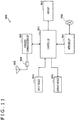
- FIG. 11 is a block diagram illustrating an example of a schematic configuration of a wireless access point 950 to which the technique according to the present disclosure can be applied.
- the wireless access point 950 includes a controller 951, a memory 952, an input device 954, a display device 955, a network interface 957, a wireless communication interface 963, an antenna switch 964, and an antenna 965.
- the controller 951 may be, for example, a CPU or a DSP (Digital Signal Processor), and the controller 951 operates various functions (for example, access restriction, routing, encryption, firewall, log management, and the like) of layers higher than an IP (Internet Protocol) layer of the wireless access point 950.
- the memory 952 includes a RAM and a ROM and stores programs executed by the controller 951 and various control data (for example, terminal list, routing table, encryption key, security setting, log, and the like).
- the input device 954 includes, for example, a button, a switch, or the like and receives an operation from the user.
- the display device 955 includes an LED lamp or the like and displays the operation status of the wireless access point 950.
- the network interface 957 is a wired communication interface for connection of the wireless access point 950 to a wired communication network 958.
- the network interface 957 may include a plurality of connection terminals.
- the wired communication network 958 may be a LAN, such as Ethernet (registered trademark), or may be a WAN (Wide Area Network).
- the wireless communication interface 963 supports one or more wireless LAN standards, such as IEEE 802.11a, 11b, 11g, 11n, 11ac, and 11ad, and serves as an access point to provide wireless connection to neighboring terminals.
- the wireless communication interface 963 can typically include a baseband processor, an RF circuit, a power amplifier, and the like.
- the wireless communication interface 963 may be a one-chip module integrating a memory that stores a communication control program, a processor that executes the program, and related circuits.
- the antenna switch 964 switches destinations of the antenna 965 between a plurality of circuits included in the wireless communication interface 963.
- the antenna 965 includes a single or a plurality of antenna elements, and the antenna 965 is used for transmission and reception of radio signals through the wireless communication interface 963.
- the NAV and ONAV management unit 212 described with reference to FIG. 2 may be implemented in the wireless communication interface 963.
- at least some of the functions may be implemented in the controller 951.
- the NAV and ONAV management unit 212 can manage the ONAV of each OBSS to perform appropriate wireless communication.
- processing procedures described in the embodiment may be regarded as a method including the series of procedures, and the processing procedures may be regarded as a program for causing a computer to execute the series of procedures or as a recording medium storing the program.
- the recording medium that can be used include a CD (Compact Disc), an MD (MiniDisc), a DVD (Digital Versatile Disc), a memory card, and a Blu-ray (registered trademark) Disc.
Landscapes
- Engineering & Computer Science (AREA)
- Computer Networks & Wireless Communication (AREA)
- Signal Processing (AREA)
- Mobile Radio Communication Systems (AREA)
Claims (13)
- Informationsverarbeitungsvorrichtung, die Folgendes umfasst:eine Antenne (209A, 209B), die dazu ausgebildet ist, Signale von Vorrichtungen in einem ersten Netzwerk zu empfangen, das die Informationsverarbeitungsvorrichtung aufweist, und von Vorrichtungen in mindestens einem weiteren Netzwerk, das die Informationsverarbeitungsvorrichtung nicht aufweist; undeine Verwaltungseinheit (212), die dazu ausgebildet ist, einen Netzwerkzuordnungsvektor (NAV), der für das erste Netzwerk eingestellt ist, und einen überlappenden NAV (ONAV), der für jedes Netzwerk des mindestens einen weiteren Netzwerks eingestellt ist, zu verwalten, wobei die Verwaltungseinheit (212) dazu ausgebildet ist, den NAV unter Verwendung einer NAV-Informationsverwaltungstabelle zu verwalten und den ONAV unter Verwendung einer ONAV-Informationsverwaltungstabelle zu verwalten;wobei als Antwort darauf, dass die Antenne einen Request-to-Send-(RTS)-Frame von einem Netzwerk in dem mindestens einen weiteren Netzwerk empfängt, die Verwaltungseinheit dazu ausgebildet ist, den ONAV für dieses Netzwerk vorläufig einzustellen, indem der ONAV als vorläufig eingestellt in der ONAV-Informationsverwaltungstabelle aufgezeichnet wird; undwobei als Antwort darauf, dass die Antenne nachfolgend von dem Netzwerk in dem mindestens einen weiteren Netzwerk einen Clear-to-Send-(CTS)-Frame empfängt, der dem RTS-Frame entspricht, wenn eine Sendeadresse in dem RTS-Frame und eine Empfangsadresse in dem CTS-Frame übereinstimmen, die Verwaltungseinheit dazu ausgebildet ist, den ONAV für dieses Netzwerk zu bestätigen, indem sie den ONAV als definitiv eingestellt in der ONAV-Informationsverwaltungstabelle aufzeichnet.
- Informationsverarbeitungsvorrichtung gemäß Anspruch 1, die Folgendes umfasst:eine Empfangsfeldstärke-Einstelleinheit (207), die dazu ausgebildet ist, einen Signalerkennungspegel der Empfangsfeldstärke einzustellen;wobei als Antwort darauf, dass der ONAV für das Netzwerk in dem mindestens einen weiteren Netzwerk vorläufig eingestellt ist, die Empfangsfeldstärke-Einstelleinheit dazu ausgebildet ist, den Signalerkennungspegel von einem normalen Schwellenwert abzusenken.
- Informationsverarbeitungsvorrichtung gemäß Anspruch 1, wobei:
die Verwaltungseinheit dazu ausgebildet ist, den ONAV für jedes Netzwerk in dem mindestens einen weiteren Netzwerk auf der Basis eines Steuersignals einzustellen, das von einer anderen Informationsverarbeitungsvorrichtung empfangen wird, die zu diesem Netzwerk gehört. - Informationsverarbeitungsvorrichtung gemäß Anspruch 1, wobei:
die Verwaltungseinheit dazu ausgebildet ist, den ONAV für jedes Netzwerk in dem mindestens einen weiteren Netzwerk auf der Basis eines Wertes einer Dauer in einem Steuersignal einzustellen, das von einer anderen Informationsverarbeitungsvorrichtung empfangen wird, die zu diesem Netzwerk gehört. - Informationsverarbeitungsvorrichtung gemäß Anspruch 1, wobei:als Antwort darauf, dass die Antenne den CTS-Frame von dem Netzwerk in dem mindestens einen weiteren Netzwerk empfängt, die Verwaltungseinheit ferner dazu ausgebildet ist, den ONAV für dieses Netzwerk als ein Verwaltungsziel einzustellen; unddie Informationsverarbeitungsvorrichtung eine Zugriffssteuereinheit (206) aufweist, die dazu ausgebildet ist, die Übertragung von Signalen durch die Antenne zu verhindern, bis alle durch die Verwaltungseinheit eingestellten Verwaltungsziele aufgehoben sind.
- Informationsverarbeitungsvorrichtung gemäß Anspruch 1, wobei:
als Antwort darauf, dass die Antenne einen Contention Free End-(CF-End)-Frame empfängt, die Verwaltungseinheit dazu ausgebildet ist, den ONAV eines Netzwerks in dem mindestens einen weiteren Netzwerk, das der Adressinformation in dem CF-END Frame entspricht, aufzuheben. - Informationsverarbeitungsvorrichtung gemäß Anspruch 1, wobei:
als Antwort auf das Empfangen eines weiteren RTS-Frames von dem ersten Netzwerk die Verwaltungseinheit dazu ausgebildet ist, den NAV des ersten Netzwerks auf der Basis eines Wertes der Dauer in dem weiteren RTS Frame einzustellen. - Informationsverarbeitungsvorrichtung gemäß Anspruch 1, wobei:
die Verwaltungseinheit dazu ausgebildet ist, den NAV, der für das erste Netzwerk eingestellt ist, und den ONAV, der für jedes Netzwerk des mindestens einen weiteren Netzwerks eingestellt ist, auf der Basis eines Typs von Steuersignalen zu verwalten, die von der Antenne von dem mindestens einen weiteren Netzwerk empfangen werden. - Informationsverarbeitungsvorrichtung gemäß Anspruch 1, wobei:
als Antwort darauf, dass die Antenne einen weiteren CTS-Frame aus dem ersten Netzwerk empfängt, die Verwaltungseinheit dazu ausgebildet ist, zu bestimmen, dass Daten im ersten Netzwerk übertragen werden sollen. - Informationsverarbeitungsvorrichtung gemäß Anspruch 1, wobei:
als Antwort darauf, dass die Antenne einen Contention Free End-(CF-END)-Frame von einem Zugangspunkt in dem ersten Netzwerk empfängt, die Verwaltungseinheit dazu ausgebildet ist, zu bestimmen, dass Daten nicht von dem Zugangspunkt in dem ersten Netzwerk übertragen werden sollen. - Kommunikationssystem, das Folgendes umfasst:die Informationsverarbeitungsvorrichtung gemäß Anspruch 1, undeine weitere Informationsverarbeitungsvorrichtung, die dazu ausgebildet ist, Signale zu senden, die von der Informationsverarbeitungsvorrichtung zu empfangen sind.
- Informationsverarbeitungsverfahren, das durch eine Informationsverarbeitungsvorrichtung durchgeführt wird, wobei das Verfahren Folgendes umfasst:Empfangen (S801) von Signalen von Vorrichtungen in einem ersten Netzwerk, das die Informationsverarbeitungsvorrichtung aufweist, und von Vorrichtungen in mindestens einem weiteren Netzwerk, das die Informationsverarbeitungsvorrichtung nicht aufweist; undVerwalten eines Netzwerk-Zuordnungsvektors (NAV), der für das erste Netzwerk eingestellt ist (S804), und eines überlappenden NAV (ONAV), der für jedes Netzwerk des mindestens einen weiteren Netzwerks eingestellt ist (S808, S809), wobei der NAV unter Verwendung einer NAV-Informationsverwaltungstabelle und der ONAV unter Verwendung einer ONAV-Informationsverwaltungstabelle verwaltet wird;als Antwort auf das Empfangen eines Request-to-Send-(RTS)-Frames (S807) von einem Netzwerk in dem mindestens einen weiteren Netzwerk, vorläufiges Einstellen (S809) des ONAV durch Aufzeichnen des ONAV als vorläufig eingestellt in der ONAV-Informationstabelle; undals Antwort auf das nachfolgende Empfangen (S807) eines dem RTS-Frame entsprechenden Clear-to-Send-(CTS)-Frames von dem genannten Netzwerk in dem mindestens einen weiteren Netzwerk, wenn eine Sendeadresse in dem RTS-Frame und eine Empfangsadresse in dem CTS-Frame übereinstimmen, Bestätigen des ONAV für dieses Netzwerk durch Aufzeichnen des ONAV als endgültig eingestellt in der ONAV-Informationsverwaltungstabelle (S808).
- Programm, das einen Computer veranlasst, das Verfahren nach Anspruch 12 auszuführen.
Applications Claiming Priority (2)
| Application Number | Priority Date | Filing Date | Title |
|---|---|---|---|
| JP2016000783 | 2016-01-06 | ||
| PCT/JP2016/083162 WO2017119184A1 (ja) | 2016-01-06 | 2016-11-09 | 情報処理装置、通信システム、情報処理方法およびプログラム |
Publications (3)
| Publication Number | Publication Date |
|---|---|
| EP3402292A1 EP3402292A1 (de) | 2018-11-14 |
| EP3402292A4 EP3402292A4 (de) | 2018-12-19 |
| EP3402292B1 true EP3402292B1 (de) | 2021-09-15 |
Family
ID=59273564
Family Applications (1)
| Application Number | Title | Priority Date | Filing Date |
|---|---|---|---|
| EP16883684.9A Active EP3402292B1 (de) | 2016-01-06 | 2016-11-09 | Informationsverarbeitungsvorrichtung, kommunikationssystem, informationsverarbeitungsverfahren und programm |
Country Status (5)
| Country | Link |
|---|---|
| US (2) | US10980061B2 (de) |
| EP (1) | EP3402292B1 (de) |
| JP (1) | JP6962198B2 (de) |
| CN (1) | CN108476524B (de) |
| WO (1) | WO2017119184A1 (de) |
Families Citing this family (5)
| Publication number | Priority date | Publication date | Assignee | Title |
|---|---|---|---|---|
| US10798740B2 (en) * | 2017-01-13 | 2020-10-06 | Nec Corporation | Wireless communication system, access point, terminal, and communication method |
| JP2020036206A (ja) * | 2018-08-30 | 2020-03-05 | 株式会社東芝 | 電子装置 |
| US11792616B2 (en) * | 2019-09-27 | 2023-10-17 | Intel Corporation | Distributed network allocation vector management for enabling vehicle-to-everything radio access technology coexistence |
| CA3162486A1 (en) | 2020-01-03 | 2021-07-08 | Virendra Singh | Smart control apparatus, system, method, and computer-readable recording media for a wireless network |
| US11399084B2 (en) * | 2020-05-12 | 2022-07-26 | Nxp Usa, Inc. | Hot plugging of sensor |
Family Cites Families (20)
| Publication number | Priority date | Publication date | Assignee | Title |
|---|---|---|---|---|
| US7164671B2 (en) * | 2001-12-27 | 2007-01-16 | Koninklijke Philips Electronics N.V. | Overlapping network allocation vector (ONAV) for avoiding collision in the IEEE 802.11 WLAN operating under HCF |
| JP4221225B2 (ja) * | 2001-05-15 | 2009-02-12 | コーニンクレッカ フィリップス エレクトロニクス エヌ ヴィ | 複数の端末間の衝突を回避する方法 |
| CN100477613C (zh) * | 2004-11-25 | 2009-04-08 | 都科摩(北京)通信技术研究中心有限公司 | 基于网络分配矢量表的分布式无线接入方法和设备 |
| KR100728039B1 (ko) * | 2006-01-05 | 2007-06-14 | 삼성전자주식회사 | 무선랜에서 히든노드에게 제어 프레임을 전달하는 방법 및장치 |
| JP4888396B2 (ja) * | 2007-03-05 | 2012-02-29 | ソニー株式会社 | 無線通信システム、無線通信装置及び無線通信方法、並びにコンピュータ・プログラム |
| KR101933738B1 (ko) * | 2011-06-24 | 2018-12-28 | 인터디지탈 패튼 홀딩스, 인크 | 광대역 및 다중 대역폭 전송 프로토콜을 지원하는 방법 및 장치 |
| CN103108364B (zh) * | 2011-11-14 | 2017-03-22 | 中国移动通信集团公司 | 通信参数确定方法、在wlan中进行通信的方法及装置 |
| CN104995960B (zh) * | 2012-10-12 | 2020-07-03 | 诺基亚技术有限公司 | 用于接入网络选择的方法和装置 |
| CA2887647C (en) | 2012-10-18 | 2017-10-10 | Lg Electronics Inc. | Method and apparatus for channel access in wireless lan system |
| KR20140088375A (ko) * | 2013-01-02 | 2014-07-10 | 삼성전자주식회사 | 무선 통신 시스템에서 기지국 간 무선 링크 복구를 위한 방법 및 장치 |
| KR20160074518A (ko) * | 2013-10-05 | 2016-06-28 | 엘지전자 주식회사 | 무선랜 시스템에서 섹터화된 전송기회를 이용한 동작 방법 및 장치 |
| US20150117366A1 (en) * | 2013-10-29 | 2015-04-30 | Qualcomm Incorporated | Systems and methods for improved communication efficiency in high efficiency wireless networks |
| US9839047B2 (en) * | 2013-12-04 | 2017-12-05 | Electronics And Telecommunications Research Institute | Methods for channel sounding and scheduling for interference alignment in wireless local area network |
| US20150296370A1 (en) * | 2014-04-09 | 2015-10-15 | Newracom, Inc. | Operation method of station based on station density in wireless local area network |
| CN105637970B (zh) * | 2014-08-26 | 2019-08-20 | 华为技术有限公司 | 接入方法和设备 |
| US9806868B2 (en) * | 2014-11-17 | 2017-10-31 | Newracom, Inc. | Frame transmitting method |
| US10588165B1 (en) * | 2014-12-08 | 2020-03-10 | Marvell Asia Pte, Ltd. | Methods and devices for communicating in a wireless network with multiple virtual access points |
| US10278022B2 (en) * | 2015-05-06 | 2019-04-30 | Qualcomm Incorporated | Communication deferral policies to increase reuse |
| US10524231B2 (en) * | 2015-05-20 | 2019-12-31 | Lg Electronics Inc. | Method for managing NAV in wireless LAN system and device for same |
| US10285203B2 (en) * | 2015-08-26 | 2019-05-07 | Newracom, Inc. | Network allocation vector types and transmission opportunity types for spatial reuse |
-
2016
- 2016-11-09 WO PCT/JP2016/083162 patent/WO2017119184A1/ja unknown
- 2016-11-09 JP JP2017560038A patent/JP6962198B2/ja active Active
- 2016-11-09 EP EP16883684.9A patent/EP3402292B1/de active Active
- 2016-11-09 CN CN201680077046.0A patent/CN108476524B/zh active Active
- 2016-11-09 US US15/777,701 patent/US10980061B2/en active Active
-
2021
- 2021-03-11 US US17/198,261 patent/US20210204319A1/en active Pending
Also Published As
| Publication number | Publication date |
|---|---|
| US20180352576A1 (en) | 2018-12-06 |
| EP3402292A4 (de) | 2018-12-19 |
| CN108476524B (zh) | 2022-06-17 |
| JP6962198B2 (ja) | 2021-11-05 |
| US20210204319A1 (en) | 2021-07-01 |
| JPWO2017119184A1 (ja) | 2018-10-25 |
| EP3402292A1 (de) | 2018-11-14 |
| CN108476524A (zh) | 2018-08-31 |
| WO2017119184A1 (ja) | 2017-07-13 |
| US10980061B2 (en) | 2021-04-13 |
Similar Documents
| Publication | Publication Date | Title |
|---|---|---|
| US20210204319A1 (en) | Information processing apparatus, communication system, information processing method, and program | |
| US10321407B2 (en) | Communication control device, communication control method, and information processing device with mode switching control | |
| US20190215841A1 (en) | Communication device, communication control method, and program | |
| US11627602B2 (en) | Information processing apparatus, communication system, information processing method, and program | |
| US20210227583A1 (en) | Communication device, communication control method, and program | |
| US10397874B2 (en) | Information processing device, communication system, information processing method, and program | |
| JP2022000985A (ja) | 情報処理装置、情報処理方法、および、プログラム | |
| US10897748B2 (en) | Information processing apparatus, communication system, information processing method, and program | |
| US11452114B2 (en) | Wireless communication control device, wireless communication control method, wireless communication device, and wireless communication method | |
| US20200322983A1 (en) | Communication apparatus, communication method, and program | |
| US11240845B2 (en) | Communication device, program, and communication method related to frame exchange | |
| JP6950688B2 (ja) | 無線通信装置および無線通信方法 | |
| WO2016092758A1 (en) | Electronic device, method, and non-transitory computer readable media | |
| JPWO2019097881A1 (ja) | 通信装置、通信システム |
Legal Events
| Date | Code | Title | Description |
|---|---|---|---|
| STAA | Information on the status of an ep patent application or granted ep patent |
Free format text: STATUS: THE INTERNATIONAL PUBLICATION HAS BEEN MADE |
|
| PUAI | Public reference made under article 153(3) epc to a published international application that has entered the european phase |
Free format text: ORIGINAL CODE: 0009012 |
|
| STAA | Information on the status of an ep patent application or granted ep patent |
Free format text: STATUS: REQUEST FOR EXAMINATION WAS MADE |
|
| 17P | Request for examination filed |
Effective date: 20180613 |
|
| AK | Designated contracting states |
Kind code of ref document: A1 Designated state(s): AL AT BE BG CH CY CZ DE DK EE ES FI FR GB GR HR HU IE IS IT LI LT LU LV MC MK MT NL NO PL PT RO RS SE SI SK SM TR |
|
| AX | Request for extension of the european patent |
Extension state: BA ME |
|
| A4 | Supplementary search report drawn up and despatched |
Effective date: 20181116 |
|
| RIC1 | Information provided on ipc code assigned before grant |
Ipc: H04W 84/12 20090101ALN20181112BHEP Ipc: H04W 74/08 20090101AFI20181112BHEP Ipc: H04W 16/14 20090101ALN20181112BHEP |
|
| DAV | Request for validation of the european patent (deleted) | ||
| DAX | Request for extension of the european patent (deleted) | ||
| STAA | Information on the status of an ep patent application or granted ep patent |
Free format text: STATUS: EXAMINATION IS IN PROGRESS |
|
| 17Q | First examination report despatched |
Effective date: 20200525 |
|
| STAA | Information on the status of an ep patent application or granted ep patent |
Free format text: STATUS: EXAMINATION IS IN PROGRESS |
|
| REG | Reference to a national code |
Ref country code: DE Ref legal event code: R079 Ref document number: 602016063863 Country of ref document: DE Free format text: PREVIOUS MAIN CLASS: H04W0074040000 Ipc: H04W0074080000 |
|
| GRAP | Despatch of communication of intention to grant a patent |
Free format text: ORIGINAL CODE: EPIDOSNIGR1 |
|
| STAA | Information on the status of an ep patent application or granted ep patent |
Free format text: STATUS: GRANT OF PATENT IS INTENDED |
|
| RIC1 | Information provided on ipc code assigned before grant |
Ipc: H04W 16/14 20090101ALN20210309BHEP Ipc: H04W 84/12 20090101ALN20210309BHEP Ipc: H04W 74/08 20090101AFI20210309BHEP |
|
| RIC1 | Information provided on ipc code assigned before grant |
Ipc: H04W 16/14 20090101ALN20210319BHEP Ipc: H04W 84/12 20090101ALN20210319BHEP Ipc: H04W 74/08 20090101AFI20210319BHEP |
|
| INTG | Intention to grant announced |
Effective date: 20210408 |
|
| RAP3 | Party data changed (applicant data changed or rights of an application transferred) |
Owner name: SONY GROUP CORPORATION |
|
| GRAS | Grant fee paid |
Free format text: ORIGINAL CODE: EPIDOSNIGR3 |
|
| GRAA | (expected) grant |
Free format text: ORIGINAL CODE: 0009210 |
|
| STAA | Information on the status of an ep patent application or granted ep patent |
Free format text: STATUS: THE PATENT HAS BEEN GRANTED |
|
| AK | Designated contracting states |
Kind code of ref document: B1 Designated state(s): AL AT BE BG CH CY CZ DE DK EE ES FI FR GB GR HR HU IE IS IT LI LT LU LV MC MK MT NL NO PL PT RO RS SE SI SK SM TR |
|
| REG | Reference to a national code |
Ref country code: CH Ref legal event code: EP |
|
| REG | Reference to a national code |
Ref country code: DE Ref legal event code: R096 Ref document number: 602016063863 Country of ref document: DE |
|
| REG | Reference to a national code |
Ref country code: IE Ref legal event code: FG4D |
|
| REG | Reference to a national code |
Ref country code: AT Ref legal event code: REF Ref document number: 1431542 Country of ref document: AT Kind code of ref document: T Effective date: 20211015 |
|
| REG | Reference to a national code |
Ref country code: NL Ref legal event code: FP |
|
| PGFP | Annual fee paid to national office [announced via postgrant information from national office to epo] |
Ref country code: NL Payment date: 20211020 Year of fee payment: 6 |
|
| REG | Reference to a national code |
Ref country code: LT Ref legal event code: MG9D |
|
| PG25 | Lapsed in a contracting state [announced via postgrant information from national office to epo] |
Ref country code: HR Free format text: LAPSE BECAUSE OF FAILURE TO SUBMIT A TRANSLATION OF THE DESCRIPTION OR TO PAY THE FEE WITHIN THE PRESCRIBED TIME-LIMIT Effective date: 20210915 Ref country code: FI Free format text: LAPSE BECAUSE OF FAILURE TO SUBMIT A TRANSLATION OF THE DESCRIPTION OR TO PAY THE FEE WITHIN THE PRESCRIBED TIME-LIMIT Effective date: 20210915 Ref country code: NO Free format text: LAPSE BECAUSE OF FAILURE TO SUBMIT A TRANSLATION OF THE DESCRIPTION OR TO PAY THE FEE WITHIN THE PRESCRIBED TIME-LIMIT Effective date: 20211215 Ref country code: LT Free format text: LAPSE BECAUSE OF FAILURE TO SUBMIT A TRANSLATION OF THE DESCRIPTION OR TO PAY THE FEE WITHIN THE PRESCRIBED TIME-LIMIT Effective date: 20210915 Ref country code: BG Free format text: LAPSE BECAUSE OF FAILURE TO SUBMIT A TRANSLATION OF THE DESCRIPTION OR TO PAY THE FEE WITHIN THE PRESCRIBED TIME-LIMIT Effective date: 20211215 Ref country code: RS Free format text: LAPSE BECAUSE OF FAILURE TO SUBMIT A TRANSLATION OF THE DESCRIPTION OR TO PAY THE FEE WITHIN THE PRESCRIBED TIME-LIMIT Effective date: 20210915 Ref country code: SE Free format text: LAPSE BECAUSE OF FAILURE TO SUBMIT A TRANSLATION OF THE DESCRIPTION OR TO PAY THE FEE WITHIN THE PRESCRIBED TIME-LIMIT Effective date: 20210915 |
|
| REG | Reference to a national code |
Ref country code: AT Ref legal event code: MK05 Ref document number: 1431542 Country of ref document: AT Kind code of ref document: T Effective date: 20210915 |
|
| PG25 | Lapsed in a contracting state [announced via postgrant information from national office to epo] |
Ref country code: LV Free format text: LAPSE BECAUSE OF FAILURE TO SUBMIT A TRANSLATION OF THE DESCRIPTION OR TO PAY THE FEE WITHIN THE PRESCRIBED TIME-LIMIT Effective date: 20210915 Ref country code: GR Free format text: LAPSE BECAUSE OF FAILURE TO SUBMIT A TRANSLATION OF THE DESCRIPTION OR TO PAY THE FEE WITHIN THE PRESCRIBED TIME-LIMIT Effective date: 20211216 |
|
| PGFP | Annual fee paid to national office [announced via postgrant information from national office to epo] |
Ref country code: IT Payment date: 20211025 Year of fee payment: 6 |
|
| PG25 | Lapsed in a contracting state [announced via postgrant information from national office to epo] |
Ref country code: AT Free format text: LAPSE BECAUSE OF FAILURE TO SUBMIT A TRANSLATION OF THE DESCRIPTION OR TO PAY THE FEE WITHIN THE PRESCRIBED TIME-LIMIT Effective date: 20210915 |
|
| PG25 | Lapsed in a contracting state [announced via postgrant information from national office to epo] |
Ref country code: IS Free format text: LAPSE BECAUSE OF FAILURE TO SUBMIT A TRANSLATION OF THE DESCRIPTION OR TO PAY THE FEE WITHIN THE PRESCRIBED TIME-LIMIT Effective date: 20220115 Ref country code: SM Free format text: LAPSE BECAUSE OF FAILURE TO SUBMIT A TRANSLATION OF THE DESCRIPTION OR TO PAY THE FEE WITHIN THE PRESCRIBED TIME-LIMIT Effective date: 20210915 Ref country code: SK Free format text: LAPSE BECAUSE OF FAILURE TO SUBMIT A TRANSLATION OF THE DESCRIPTION OR TO PAY THE FEE WITHIN THE PRESCRIBED TIME-LIMIT Effective date: 20210915 Ref country code: RO Free format text: LAPSE BECAUSE OF FAILURE TO SUBMIT A TRANSLATION OF THE DESCRIPTION OR TO PAY THE FEE WITHIN THE PRESCRIBED TIME-LIMIT Effective date: 20210915 Ref country code: PT Free format text: LAPSE BECAUSE OF FAILURE TO SUBMIT A TRANSLATION OF THE DESCRIPTION OR TO PAY THE FEE WITHIN THE PRESCRIBED TIME-LIMIT Effective date: 20220117 Ref country code: PL Free format text: LAPSE BECAUSE OF FAILURE TO SUBMIT A TRANSLATION OF THE DESCRIPTION OR TO PAY THE FEE WITHIN THE PRESCRIBED TIME-LIMIT Effective date: 20210915 Ref country code: ES Free format text: LAPSE BECAUSE OF FAILURE TO SUBMIT A TRANSLATION OF THE DESCRIPTION OR TO PAY THE FEE WITHIN THE PRESCRIBED TIME-LIMIT Effective date: 20210915 Ref country code: EE Free format text: LAPSE BECAUSE OF FAILURE TO SUBMIT A TRANSLATION OF THE DESCRIPTION OR TO PAY THE FEE WITHIN THE PRESCRIBED TIME-LIMIT Effective date: 20210915 Ref country code: CZ Free format text: LAPSE BECAUSE OF FAILURE TO SUBMIT A TRANSLATION OF THE DESCRIPTION OR TO PAY THE FEE WITHIN THE PRESCRIBED TIME-LIMIT Effective date: 20210915 Ref country code: AL Free format text: LAPSE BECAUSE OF FAILURE TO SUBMIT A TRANSLATION OF THE DESCRIPTION OR TO PAY THE FEE WITHIN THE PRESCRIBED TIME-LIMIT Effective date: 20210915 |
|
| REG | Reference to a national code |
Ref country code: DE Ref legal event code: R097 Ref document number: 602016063863 Country of ref document: DE |
|
| PG25 | Lapsed in a contracting state [announced via postgrant information from national office to epo] |
Ref country code: MC Free format text: LAPSE BECAUSE OF FAILURE TO SUBMIT A TRANSLATION OF THE DESCRIPTION OR TO PAY THE FEE WITHIN THE PRESCRIBED TIME-LIMIT Effective date: 20210915 |
|
| REG | Reference to a national code |
Ref country code: CH Ref legal event code: PL |
|
| PLBE | No opposition filed within time limit |
Free format text: ORIGINAL CODE: 0009261 |
|
| STAA | Information on the status of an ep patent application or granted ep patent |
Free format text: STATUS: NO OPPOSITION FILED WITHIN TIME LIMIT |
|
| PG25 | Lapsed in a contracting state [announced via postgrant information from national office to epo] |
Ref country code: LU Free format text: LAPSE BECAUSE OF NON-PAYMENT OF DUE FEES Effective date: 20211109 Ref country code: DK Free format text: LAPSE BECAUSE OF FAILURE TO SUBMIT A TRANSLATION OF THE DESCRIPTION OR TO PAY THE FEE WITHIN THE PRESCRIBED TIME-LIMIT Effective date: 20210915 Ref country code: BE Free format text: LAPSE BECAUSE OF NON-PAYMENT OF DUE FEES Effective date: 20211130 |
|
| REG | Reference to a national code |
Ref country code: BE Ref legal event code: MM Effective date: 20211130 |
|
| 26N | No opposition filed |
Effective date: 20220616 |
|
| PG25 | Lapsed in a contracting state [announced via postgrant information from national office to epo] |
Ref country code: SI Free format text: LAPSE BECAUSE OF FAILURE TO SUBMIT A TRANSLATION OF THE DESCRIPTION OR TO PAY THE FEE WITHIN THE PRESCRIBED TIME-LIMIT Effective date: 20210915 Ref country code: LI Free format text: LAPSE BECAUSE OF NON-PAYMENT OF DUE FEES Effective date: 20211130 Ref country code: CH Free format text: LAPSE BECAUSE OF NON-PAYMENT OF DUE FEES Effective date: 20211130 |
|
| PG25 | Lapsed in a contracting state [announced via postgrant information from national office to epo] |
Ref country code: IE Free format text: LAPSE BECAUSE OF NON-PAYMENT OF DUE FEES Effective date: 20211109 |
|
| PG25 | Lapsed in a contracting state [announced via postgrant information from national office to epo] |
Ref country code: FR Free format text: LAPSE BECAUSE OF NON-PAYMENT OF DUE FEES Effective date: 20211115 |
|
| PG25 | Lapsed in a contracting state [announced via postgrant information from national office to epo] |
Ref country code: CY Free format text: LAPSE BECAUSE OF FAILURE TO SUBMIT A TRANSLATION OF THE DESCRIPTION OR TO PAY THE FEE WITHIN THE PRESCRIBED TIME-LIMIT Effective date: 20210915 |
|
| REG | Reference to a national code |
Ref country code: NL Ref legal event code: MM Effective date: 20221201 |
|
| P01 | Opt-out of the competence of the unified patent court (upc) registered |
Effective date: 20230527 |
|
| PG25 | Lapsed in a contracting state [announced via postgrant information from national office to epo] |
Ref country code: HU Free format text: LAPSE BECAUSE OF FAILURE TO SUBMIT A TRANSLATION OF THE DESCRIPTION OR TO PAY THE FEE WITHIN THE PRESCRIBED TIME-LIMIT; INVALID AB INITIO Effective date: 20161109 |
|
| PG25 | Lapsed in a contracting state [announced via postgrant information from national office to epo] |
Ref country code: NL Free format text: LAPSE BECAUSE OF NON-PAYMENT OF DUE FEES Effective date: 20221201 |
|
| PG25 | Lapsed in a contracting state [announced via postgrant information from national office to epo] |
Ref country code: IT Free format text: LAPSE BECAUSE OF NON-PAYMENT OF DUE FEES Effective date: 20221109 |
|
| PGFP | Annual fee paid to national office [announced via postgrant information from national office to epo] |
Ref country code: GB Payment date: 20231019 Year of fee payment: 8 |
|
| PGFP | Annual fee paid to national office [announced via postgrant information from national office to epo] |
Ref country code: DE Payment date: 20231019 Year of fee payment: 8 |
|
| PG25 | Lapsed in a contracting state [announced via postgrant information from national office to epo] |
Ref country code: MK Free format text: LAPSE BECAUSE OF FAILURE TO SUBMIT A TRANSLATION OF THE DESCRIPTION OR TO PAY THE FEE WITHIN THE PRESCRIBED TIME-LIMIT Effective date: 20210915 |