WO2016092758A1 - Electronic device, method, and non-transitory computer readable media - Google Patents
Electronic device, method, and non-transitory computer readable media Download PDFInfo
- Publication number
- WO2016092758A1 WO2016092758A1 PCT/JP2015/005869 JP2015005869W WO2016092758A1 WO 2016092758 A1 WO2016092758 A1 WO 2016092758A1 JP 2015005869 W JP2015005869 W JP 2015005869W WO 2016092758 A1 WO2016092758 A1 WO 2016092758A1
- Authority
- WO
- WIPO (PCT)
- Prior art keywords
- electronic device
- transmission power
- information
- data
- circuitry
- Prior art date
Links
Images


Classifications
-
- H—ELECTRICITY
- H04—ELECTRIC COMMUNICATION TECHNIQUE
- H04W—WIRELESS COMMUNICATION NETWORKS
- H04W52/00—Power management, e.g. TPC [Transmission Power Control], power saving or power classes
- H04W52/04—TPC
- H04W52/18—TPC being performed according to specific parameters
- H04W52/26—TPC being performed according to specific parameters using transmission rate or quality of service QoS [Quality of Service]
- H04W52/267—TPC being performed according to specific parameters using transmission rate or quality of service QoS [Quality of Service] taking into account the information rate
-
- H—ELECTRICITY
- H04—ELECTRIC COMMUNICATION TECHNIQUE
- H04W—WIRELESS COMMUNICATION NETWORKS
- H04W52/00—Power management, e.g. TPC [Transmission Power Control], power saving or power classes
- H04W52/04—TPC
- H04W52/18—TPC being performed according to specific parameters
- H04W52/28—TPC being performed according to specific parameters using user profile, e.g. mobile speed, priority or network state, e.g. standby, idle or non transmission
-
- H—ELECTRICITY
- H04—ELECTRIC COMMUNICATION TECHNIQUE
- H04W—WIRELESS COMMUNICATION NETWORKS
- H04W52/00—Power management, e.g. TPC [Transmission Power Control], power saving or power classes
- H04W52/04—TPC
- H04W52/38—TPC being performed in particular situations
- H04W52/46—TPC being performed in particular situations in multi hop networks, e.g. wireless relay networks
Definitions
- the present technology relates to an information processor. More specifically, the present technology relates to an information processor and an information processing method to handle information related to radio communication, and a program causing a computer to execute the method.
- radio communication technology in which various kinds of data are exchanged by utilizing radio communication.
- a communication method to autonomously interconnect with an information processor present in a surrounding area for example, ad hoc communication and an ad hoc network.
- radio multi-hop communication device in which a node constituting a radio multi-hop network exchanges a state of received radio with an adjacent node by transmitting and receiving a packet of transmission power control (refer to Patent Literature 1, for example).
- the radio multi-hop communication device reduces transmission power down to a level not to destabilize communication with another adjacent node with which a direct communication route is provided.
- radio interference can be reduced by reducing the transmission power.
- the transmission power is reduced more than necessary because transmitting condition of the adjacent node is not considered. Accordingly, appropriately setting transmission power by considering the transmitting condition of the adjacent node is important.
- the present technology is made in view of the above situation, and directed to appropriately setting the transmission power.
- the disclosure is directed to an electronic device that receives information transmitted from at least one other electronic device; determines a transmission power of the electronic device based on the information; determines whether the transmission power satisfies a predetermined condition; and determines an update to the transmission power that is applied in transmitting data to the at least one other electronic device in a case that transmission power does not satisfy the predetermined condition.
- the electronic device may be configured to identify a number of the other electronic devices based on the information and determine the transmission power of the electronic device based on the number of other electronic devices.
- the electronic may be configured to determine the transmission power to be a first value in a case that the number of other electronic devices is below a threshold number and a second value in a case that the number of electronic devices is greater than the threshold number, the first value being greater than the second value.
- the information may indicate at least one of a transmission power characteristic of the at least one other electronic device or a transmitting state of the at least one other electronic device.
- the electronic device may be configured to determine the transmission power of the electronic device based on the transmission power characteristic of the at least one other electronic device.
- the electronic device may be configured to control a communication interface to transmit a notification indicating the new transmission power.
- the electronic device may be configured to communicate with the at least one other electronic device via an ad hoc network formed between the electronic device and the at least one other electronic device.
- the electronic device may be configured to detect a new electronic device to the ad hoc network based on information transmitted from the new electronic device, and update the transmission power based on the detection of the new electronic device.
- the ad hoc network may be a mesh network that applies carrier sense multiple access (CSMA).
- the predetermined condition may correspond to whether an amount of data to be transmitted by the electronic device is less than a threshold value.
- the electronic device may be configured to not change the transmission power in a case that the amount of data to be transmitted by the electronic device is less than the threshold value.
- the electronic device may be configured to update the transmission power by increasing the transmission power in a case that the amount of data to be transmitted by the electronic device is greater than the threshold value.
- the electronic device may be configured to update the transmission power by increasing the transmission power in a stepwise manner based on the amount of data to be transmitted by the electronic device.
- the electronic device may be configured to control transmitting a control signal indicating the updated transmission power to the at least one other electronic device.
- the predetermined condition may correspond to whether a Quality of Service (QoS) level of data to be transmitted by the electronic device is less than a threshold QoS level.
- QoS Quality of Service
- the electronic device may be configured to not change the transmission power in a case that the QoS level of data to be transmitted by the electronic device is less than the threshold QoS level.
- the electronic device may be configured to update the transmission power by increasing the transmission power in a case that the QoS level of data to be transmitted by the electronic device is greater than the threshold QoS level.
- the electronic device may be configured to update the transmission power by increasing the transmission power in a stepwise manner for each QoS level the data to be transmitted is greater than the threshold QoS level.
- the electronic device may be configured to control transmitting a control signal indicating the updated transmission power to the at least one other electronic device.
- the predetermined condition may correspond to whether a difference between a transmission rate of data received at the electronic device and a transmission rate of data transmitted from the electronic device is less than a threshold value.
- the electronic device may be configured to not change the transmission power in a case that the difference between the transmission rate of data received at the electronic device and the transmission rate of data transmitted from the electronic device is less than the threshold value.
- the electronic device may be configured to update the transmission power by increasing the transmission power in a case that the difference between the transmission rate of data received at the electronic device and the transmission rate of data transmitted from the electronic device is greater than the threshold value.
- the electronic device may be configured to control transmitting a control signal indicating the updated transmission power to the at least one other electronic device.
- the electronic device may be configured to identify a number of hops that the information traversed prior to arriving at the electronic device.
- the electronic device may be configured to determine the transmission power of the electronic device based on the number of hops that the information traversed prior to arriving at the electronic device.
- the electronic device may be configured to determine the transmission power to be a first value in a case that the number of hops is below a threshold number and a second value in a case that the number of hops is greater than the threshold number, the first value being greater than the second value.
- the disclosure is directed to a method performed by an electronic device, the method including: receiving, by a communication interface of the electronic device, information transmitted from at least one other electronic device; determining, by circuitry of the electronic device, a transmission power of the electronic device based on the information; determining, by the circuitry, whether the transmission power satisfies a predetermined condition; and determining, by the circuitry, an update to the transmission power that is applied in transmitting data to the at least one other electronic device in a case that transmission power does not satisfy the predetermined condition.
- the disclosure is directed to one or more non-transitory computer-readable media including computer program instructions, which when executed by an electronic device, cause the electronic device to: receive information transmitted from at least one other electronic device; determine a transmission power of the electronic device based on the information; determine whether the transmission power satisfies a predetermined condition; and update transmission power in transmitting data to the at least one other electronic device in a case that transmission power does not satisfy the predetermined condition.
- the disclosure is directed to an electronic device including: circuitry configured to identify a first transmission rate of data received at the electronic device; identify a second transmission rate of data transmitted from the electronic device; and determine a transmission power for transmitting date from the electronic device based on a difference between the first transmission rate and the second transmission rate.
- the disclosure is directed to an electronic device comprising: circuitry configured to generate, based on a data transmitting state of the electronic device, control information to request at least one other electronic device to reduce transmission power; and transmit the control information to the at least one other electronic device.
- Fig. 1 is a diagram illustrating an exemplary system configuration of a communication system 10 according to a first embodiment of the present technology.
- Fig. 2 is a block diagram illustrating an exemplary internal configuration of an information processor 100 according to the first embodiment of the present technology.
- Figs. 3A to 3C are diagrams illustrating comparative examples of transmission power control which can be executed by the communication system according to the first embodiment of the present technology.
- Figs. 4A to 4C are diagrams illustrating exemplary formats of control information (control signals) exchanged between respective information processors constituting the communication system 10 according to the first embodiment of the present technology.
- Figs. 1 is a diagram illustrating an exemplary system configuration of a communication system 10 according to a first embodiment of the present technology.
- Fig. 2 is a block diagram illustrating an exemplary internal configuration of an information processor 100 according to the first embodiment of the present technology.
- Figs. 3A to 3C are diagrams illustrating comparative examples of transmission power control which can be executed by the communication system
- FIGS. 5A and 5B are diagrams illustrating a flow of control information exchanged between the respective information processors constituting the communication system 10 according to the first embodiment of the present technology, and exemplary acquired control information.
- Fig. 6 is a diagram illustrating an example of held control information acquired by an information processor 102 according to the first embodiment of the present technology.
- Fig. 7 is a diagram illustrating an exemplary setting for a requesting level by the information processor 100 according to the first embodiment of the present technology.
- Fig. 8 is a diagram illustrating an exemplary setting for the requesting level by the information processor 100 according to the first embodiment of the present technology.
- Fig. 9 is a diagram illustrating an exemplary setting for the requesting level by the information processor 100 according to the first embodiment of the present technology.
- Fig. 6 is a diagram illustrating an example of held control information acquired by an information processor 102 according to the first embodiment of the present technology.
- Fig. 7 is a diagram illustrating an exemplary setting for a requesting level by the information
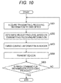
- FIG. 10 is a flowchart illustrating an exemplary transmission procedure in transmission processing by the information processor 100 according to the first embodiment of the present technology.
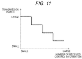
- Fig. 11 is a diagram illustrating an exemplary setting for transmission power by the information processor 100 according to the first embodiment of the present technology.
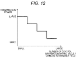
- Fig. 12 is a diagram illustrating an exemplary setting for transmission power by the information processor 100 according to the first embodiment of the present technology.
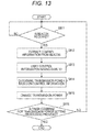
- Fig. 13 is a flowchart illustrating an exemplary procedure for setting the transmission power by the information processor 100 according to the first embodiment of the present technology.
- Fig. 14 is a flowchart illustrating an exemplary procedure for setting the transmission power by an information processor 100 according to a second embodiment of the present technology.
- Fig. 11 is a diagram illustrating an exemplary setting for transmission power by the information processor 100 according to the first embodiment of the present technology.
- Fig. 12 is a diagram illustrating an exemplary setting for transmission power by the information processor 100 according to the first embodiment of the present technology.
- Fig. 13 is
- FIG. 15 is a diagram illustrating an exemplary setting for transmission power by an information processor 100 according to a third embodiment of the present technology.
- Fig. 16 is a flowchart illustrating an exemplary procedure for setting the transmission power by an information processor 100 according to the third embodiment of the present technology.
- Fig. 17 is a block diagram illustrating an exemplary schematic configuration of a smartphone.
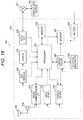
- Fig. 18 is a block diagram illustrating an exemplary schematic configuration of a car navigation device.
- Embodiments to implement the present technology will be described below (hereinafter referred to as the embodiments). A description will be given in the following order.
- First embodiment example of controlling transmission power based on a data transmitting state of an information processor present in a surrounding area
- Second embodiment example of controlling transmission power based on a data transmitting state of an information processor present in a surrounding area and a data transmitting state of an own device
- Third embodiment example of controlling transmission power based on a comparison result between received data to be an object of transfer to another information processor and the transmission data to be transferred
- FIG. 1 is a diagram illustrating an exemplary system configuration of a communication system 10 according to a first embodiment of the present technology.
- the communication system 10 is an example of a radio communication system configured by an information processor which confirms an occupied state of media (such as channel and resource) prior to transmission, and performs transmission in the case where the media is cleared.
- the communication system 10 includes information processors 100 to 105.
- a relation between information processors that can directly communicate is indicated by arrows of dotted lines.
- Each of the information processors (devices) constituting the communication system 10 is, for example, a portable information processor and a fixed information processor having a radio communication function.
- the portable information processor is a radio communication device such as a smartphone, a mobile phone, and a tablet terminal
- the fixed information processor is an information processor such as a printer and a personal computer.
- each of the electronic devices can be an electronic device such as a sensor, a television, a projector, a hard disk recorder, a speaker, a microphone, an access point, a personal computer (PC), or a display.
- each of the electronic devices can be an electronic device such as a drone, a medical device, a surgical device, a patient tracking monitor, gaming device, a Blu-ray disc player, a printer, a light with a sensor, an automatic door, a security device, or a disaster prevention device.
- each of the electronic devices is a tablet, a smartphone, a photo frame, a refrigerator, an air conditioner, an air cleaner, a vacuum cleaner (such as self-propelled vacuum cleaner), a laundry machine, a microwave, a toaster, a ventilation fan, or a radio.
- ad hoc communication As a communication method to autonomously interconnect with an information processor (node) present in the surrounding area, ad hoc communication, an ad hoc network, etc. are known.
- each information processor and an information processor present in the surrounding area can communicate each other without relying on a master station. More specifically, control information is exchanged between the information processors adjacent to each other, and communication with another information processor can be performed by autonomously forming a network. Therefore, according to the embodiment of the present technology, a description will be given by exemplifying the ad hoc network as a communication method to autonomously interconnect with the information processor present in the surrounding area.
- the master station is a control device that performs centralized control like an access point of a radio local area network (LAN) and a base station of mobile phones.
- LAN radio local area network
- the new information processor can also freely participate in the network.
- the respective information processors in Fig. 1 assume the case where only the information processor 100 and the information processor 101 can participate in the ad hoc network.
- an information processor 102 and an information processor 103 are sequentially added.
- a range covered by the network can be increased in accordance with addition of the respective information processors (information processors present in the surrounding area). More specifically, the range covered by the network can be increased by sequentially adding the information processor 102 and information processor 103.
- the respective information processors can also transfer information exchanged with other information processors in a bucket brigade manner in addition to autonomously interconnecting with the information processors present in the surrounding area.
- the respective information processors not only transmit and receive data of the own device (traffic) but also can relay data which other information processors transmit and receive (traffic).
- the information processor 102 can directly communicate with the information processors 100, 101, 103, but cannot directly communicate with the information processors 104, 105 for the reason, for example, that the radio waves cannot reach.
- the information processors 100, 101, 103 which can directly communicate with the information processor 102 can transfer data of the information processor 102 to the information processor 105. Accordingly, by thus transferring the data, the information processor 102 and the information processor 105 which cannot directly communicating with the information processor 102 can mutually exchange information via the information processors 100, 101, 103. More specifically, the information processor 102 cannot directly communicate with the information processor 105, but can communicate with the information processor 105 by the information processor 100 or the like relaying the data of the information processor 102. In the same manner, the information processor 102 can communicate with the information processor 104.
- multi-hop relay The method in which data transfer is thus transferred by a relay node (namely, bucket brigade) to communicate with a distant information processor is called multi-hop relay.
- the network performing the multi-hop is generally known as a mesh network.
- the standards such as Institute of Electrical and Electronic Engineers (IEEE) 802.11s-2011 are known.
- the communication system 10 is an exemplary network in which a plurality of information processors is mutually connected by the plurality of information processors performing one-to-one radio communication.
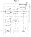
- FIG. 2 is a block diagram illustrating an exemplary internal configuration of the information processor 100 according to the first embodiment of the present technology. Note that a description will be given only for the internal configuration of the information processor 100 here, and a description for those of other information processors (information processors 101 to 105) will be omitted for being same as the information processor 100.
- the information processor 100 includes a transmitting unit 110, a receiving unit 120, a control unit 130, a memory 140, and an antenna 150. Note that only the components related to radio communication will be mainly described in Fig. 2, and a description and illustration for other components will be omitted.
- the transmitting unit 110 includes a channel encoder 111, a modulator 112, and a radio frequency (RF) transmitter 113.
- RF radio frequency
- the channel encoder 111 encodes the data to be transmitted based on control of the control unit 130 and also applies error correction encoding, and then outputs, to the modulator 112, the data applied with the error correction encoding.
- the modulator 112 demodulates, based on control of the control unit 130, the data applied with the error correction encoding by the channel encoder 111, and outputs the modulated data (modulation signal) to the RF transmitter 113.
- the RF transmitter 113 amplifies, based on control of the control unit 130, the modulation signal output from the modulator 112, and transmits the amplified demodulation signal via the antenna 150. For example, the RF transmitter 113 amplifies the modulation signal output from the modulator 112 to power corresponding to an indication value of transmission power output from the control unit 130, and transmits the amplified demodulation signal via the antenna 150.
- the receiving unit 120 includes an RF receiver 121, a demodulator 122, and a channel decoder 123.
- the RF receiver 121 converts, based on control of the control unit 130, a signal received via the antenna 150 (received signal) to a baseband signal, and outputs the baseband signal to the demodulator 122.
- the demodulator 122 demodulates, based on control of the control unit 130, the baseband signal output from the RF receiver 121, and outputs the demodulated signal to the channel decoder 123.
- the channel decoder 123 applies, based on control of the control unit 130, error correction and decoding to the signal demodulated by the demodulator 122, and outputs the data applied with error correction and decoding.
- the transmitting unit 110 and the receiving unit 120 can perform radio communication by millimeter-wave communication (such as 60 GHz), a radio LAN of 900 MHz/2.4 GHz/5 GHz, and an ultra wide band (UWB). Further, for example, the transmitting unit 110 and the receiving unit 120 can perform radio communication by visible light communication and near field communication (NFC).
- millimeter-wave communication such as 60 GHz
- radio LAN of 900 MHz/2.4 GHz/5 GHz
- UWB ultra wide band
- the transmitting unit 110 and the receiving unit 120 can perform radio communication by visible light communication and near field communication (NFC).
- NFC near field communication
- the transmitting unit 110 and the receiving unit 120 may perform radio communication using radio waves (electromagnetic waves), and may also perform radio communication using a medium other than radio waves (for example, radio communication using a magnetic field).
- radio waves electromagnetic waves
- a medium other than radio waves for example, radio communication using a magnetic field
- the control unit 130 controls respective units of the information processor 100 based on a control program stored in the memory 140.
- the control unit 130 applies signal processing to the information transmitted and received.
- the control unit 130 is implemented by a central processing unit (CPU), for example.
- control unit 130 controls transmission power based on a characteristic amount output from the transmitting unit 110 and the receiving unit 120 (for example, transmitting/receiving information of the own device). For example, the control unit 130 generates an indication value of transmission power, and outputs the indication value of transmission power to the RF transmitter 113 based on the characteristic amount output from the transmitting unit 110 and the receiving unit 120.
- control unit 130 generates and transmits, based on a data transmitting state of the information processor 100, the control information to request an information processor present in the surrounding area so as to reduce the transmission power. Further, for example, the control unit 130 controls transmission power based on the data transmitting state of the information processor present in the surrounding area.
- control unit 130 transfers the control information to another information processor until the number of transfer of the control information reaches a setting value (e.g., 1).
- the memory 140 is a memory to store various kinds of information. For example, various kinds of information needed for the information processor 100 to perform predetermined operation (for example, control program) are stored in the memory 140. Further, the control information received by the information processor 100 is stored in the memory 140 per information processor (for example, control information illustrated in Fig. 4C).
- CSMA carrier sense multiple access
- the number of transmitting opportunity is reduced in accordance with a data amount transmitted on the same channel (traffic amount).
- a data amount transmitted on the same channel traffic amount.
- the data amount is increased, an interference amount given to the adjacent information processor is increased, and there may be a risk in which a band used by the adjacent information processor is limited and transmission opportunity of the adjacent information processor is reduced.
- the data transmission by the own device may limit the transmission opportunity of other information processors. For example, in the case where a transmitting environment of a link performing data transmission is good, data transmission is performed with transmission power more than necessary, thereby reducing the transmission opportunity of another information processor. In other words, data transmission by the own device may increase unnecessary interference.
- the transmission power may be controlled in accordance with a transmitting condition of the own device. For example, assume the case where the transmission power of the own device is reduced when the information processor present in the surrounding area does not transmit data. In this case, interference with another information processor is reduced, and transmission opportunity of another information processor can be increased while influence is not given to another information processor because another information processor does not transmit data. However, in this case, a transmission data rate of the own device is lowered, and throughput is reduced.
- the transmission power may also be controlled in accordance with the number of adjacent information processors and the number of the information processors present in the surrounding area (nodes next to an adjacent node) detected by an adjacent information processor, and in accordance with distances from these information processors.
- the transmission power is reduced more than necessary because the transmitting condition of another information processor cannot be grasped.
- the transmission power of the own device in accordance with the transmitting condition of the own device, the number of information processors present in the surrounding area, and the distance therebetween, the transmission power may be reduced more than necessary, and there may be a risk that throughput of an entire system is decreased. In other words, system capacity such as the throughput of the entire system is not necessarily increased.
- throughput of a flow is determined by a transmission rate of a path which is to be the lowest transmission rate.
- the path having the high transmission rate does not contribute to improving the throughput of the flow. Therefore, in the case of not controlling the transmission power, the transmission power more than necessary is used for transmission at a high transmission rate, and there may be a risk that interference with the information processor present in the surrounding area is increased.
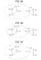
- FIGs. 3A to 3C are diagrams illustrating comparative examples of transmission power control which can be performed in the communication system according to the first embodiment of the present technology.
- exemplary relations between a mesh network formed of mesh information processors 21 to 24 and a mesh network formed of information processors 31 to 33 are illustrated.
- a relation in which the information processors can perform direct communication is indicated by arrows of dotted lines.
- a communicable range of the information processor 21 is schematically illustrated by ellipses 41 to 43 of dotted lines.
- Figs. 3A to 3C illustrated are the comparative examples in the case of reducing interference and increasing transmission opportunity by controlling the transmission power in the mesh network (IEEE 802.11s, for example).
- IEEE 802.11s IEEE 802.11s
- Fig. 3A illustrates an exemplary network configuration in the case of not controlling the transmission power. Further, Fig. 3A illustrates the exemplary case where the information processor 21 and the information processor 31 respectively perform data communication with adjacent information processors.
- the information processor 31 receives transmission data from the information processor 21 because the information processor 31 is included in the communicable range of the information processor 21 (ellipse 41 indicated by a dotted line).
- the information processor 31 receives the transmission data from the information processor 21 because data transmission is needed to be stopped until a channel is cleared. Therefore, the transmission opportunity of the information processor 31 is reduced.
- Fig. 3B illustrates an exemplary network configuration in the case of controlling the transmission power. Further, Fig. 3B illustrates an exemplary case where the information processor 21 and the information processor 31 respectively perform data communication with adjacent information processors.
- the communicable range of the information processor 21 becomes smaller by reducing the transmission power of the information processor 21. Therefore, data from the information processor 21 hardly reaches the information processor 31. By this, the information processor 31 can transmit data of the own device and the transmission opportunity thereof is increased regardless of performance of data transmission by the information processor 21. Further, interference power given to the information processors 32, 33 from the information processor 21 is also reduced, thereby improving communicating conditions of the information processors 32, 33.
- a transmitting rate of the data transmitted by the information processor 21 is also reduced by the information processor 21 reducing the transmission power.
- the information processor 31 performs data transmission, throughput and the like of the entire network is increased due to increase of the transmission opportunity of the information processor 31.
- the throughput of the entire network is reduced by a decreased amount of the transmitting rate of the information processor 21.
- Fig. 3C illustrates an exemplary network configuration in the case of controlling transmission power based on transmitting states of the information processors present in the surrounding area. Further, Fig. 3C illustrates the exemplary case where the information processor 31 does not perform data communication with the adjacent information processors.
- the information processor 21 increases transmission power. By this, the transmission rate of the information processor 21 can be increased, and the throughput can be improved.
- the transmission power of the own device is increased.
- the transmission power of the own device is reduced. As a result, transmission opportunity of the information processors present in the surrounding area can be increased.
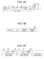
- FIGs. 4A to 4C are diagrams illustrating exemplary formats of control information (control signal) exchanged between respective information processors constituting the communication system 10 according to the first embodiment of the present technology.
- the respective information processors constituting the communication system 10 exchange packet-form signals at the time of communication. Further, each of the information processors constituting the communication system 10 notifies the information processors present in the surrounding area of the transmitting state of the own device. Therefore, control information (control signal) is transmitted at regular intervals (or at necessary timing). The control information is used as a notification to request another information processor so as to reduce the transmission power.
- each of the information processors constituting the communication system 10 notifies the plurality of information processors of the transmitting state of the own device, preferably, the control information is transmitted in a broadcast frame. Therefore, according to the first embodiment of the present technology, provided is an example of superimposing the control information on a beacon frame (exemplary implementation on the beacon frame) in order to avoid increase of a new control frame. Further, Figs. 4A to 4C illustrate examples of using the beacon frame based on IEEE 802.11. Note that the beacon frame is one of a management frame.
- beacon information other than the beacon may be used as well.
- a Probe request used in broadcast transmission and scanning may be used.
- Fig. 4A is an exemplary media access control (MAC) frame format of the management frame.
- a MAC header is from a frame control field to a high throughput (HT) control field.
- an Information Element of the beacon frame is stored in a frame body field.
- information such as a time stamp, a beacon cycle, and a service set identifier (SSID) is stored.
- SSID service set identifier
- a Vendor-specific element which can be uniquely implemented by a vendor is prepared. This exemplary format is illustrated in Fig. 4B.
- Fig. 4B illustrates an exemplary format of a Vendor-specific element.
- the format of the Vendor-specific element illustrated in Fig. 4B is stored in a part of a frame body field illustrated in Fig. 4A.
- control information (control signal) is stored in the Vendor-specific content 200 illustrated in Fig. 4B.
- An exemplary format of the control information is illustrated in Fig. 4C.
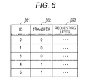
- the control information is formed of ID fields 201, 211, transfer fields 202, 212, and requesting level fields 203, 213.
- One in each of the ID field, transfer field, and requesting level field are stored per information processor.
- the control information (ID field, transfer field, and requesting level field) related to the own device is arranged first, and then the control information (ID field, transfer field, and requesting level field) related to other devices is arranged next.
- the control information of the corresponding number (the number of information processors to which the control information is to be transmitted) is sequentially arranged. Note that the order of arrangement can be determined in accordance with a predetermined rule (for example, order of receipt).
- IDs to identify the information processors in the network are stored. Note that according to the first embodiment of the present technology, a description will be given defining the IDs of the information processors 100 to 105 as 0 to 5 to simplify the description.
- the transfer fields 202, 212 the number of times corresponding control information has been transferred is stored. For example, 0 is stored in the transfer field 202 of the own device in the control information transmitted by the own device. Further, 1 is added to the value of the transfer field every time transfer is performed.
- requesting level fields 203, 213 stored are values corresponding to requesting levels in order to ask the information processors present in the surrounding area to reduce the transmission power.
- the value of the requesting level is increased. In contrast, in the case of not requesting so, the value of the requesting level is decreased.
- a range of the value of the requesting level may be any of binary and multiple values.
- the requesting level field may be omitted in the control information. In this case, for example, a receiving-side information processor can determine a requesting level based on presence of the requesting level field.
- the information processor having received the control information illustrated in Fig. 4C adds the received control information to the beacon of the own device, and transmits the same.
- 1 is added to the value of the transfer field (e.g., transfer field 212 illustrated in Fig. 4C).
- the control information is unified. In this case, when the values of the transfer field are different, the control information having a smaller value in the transfer field is adopted.
- the control information may be prevented from being transferred.
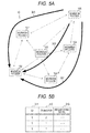
- FIGs. 5A and 5B are diagrams illustrating a flow of control information exchanged between the respective information processors constituting the communication system 10 according to the first embodiment of the present technology, and exemplary acquired control information.
- Figs. 5A and 5B the exemplary case where the information processors 100 to 105 are arranged based on a topology illustrated in Fig. 1.
- Fig. 5A illustrates the flow in which the control information transmitted from the information processor 105 reaches the information processor 102 in the communication system 10.
- Fig. 5B illustrates the exemplary control information acquired by the information processor 102 in the example of Fig. 5A.
- the control information transmitted by the information processor 105 is transferred by the information processor 100, information processor 101, information processor 104, and information processor 103, and reaches the information processor 102.
- the flow of the control information is indicated by arrows 301 to 303 of thick lines.
- the information processor 102 receives the control information of the information processor 105 from each of the information processor 100, information processor 101, and information processor 103.
- the control information is held in a memory of the information processor 102 (corresponding to a memory 140 in Fig. 2).
- Fig. 5B the control information which the information processor 102 received from the information processor 103 via the information processor 104 is shown in an upper row. Further, the control information which the information processor 102 received from the information processor 100 is shown in a middle row. Further, the control information which the information processor 102 received from the information processor 101 is shown in a lower row. In this case, each of the ID fields 311 indicates "5" representing the information processor 105. Further, the values in the transfer field 312 are 2, 1, and 1 respectively. More specifically, the control information in the upper row of Fig. 5B is 2 because the control information is received from the information processor 103 via the information processor 104. On the other hand, the control information in the middle row of Fig.
- the information processor 102 transmits the control information related to the own device together with the received control information.
- the information processor 102 adds 1 to the value of the transfer field of the control information related to the information processor 105, and then transmits the same. More specifically, the information processor 102 stores "5" in the ID field as the control information related to the information processor 105, stores "2" in the transfer field, and stores a received requesting level in the requesting level as it is, and then transmits the control information.
- the number of control information to be exchanged is increased. Further, since interference power is generally reduced as the number of transfer is increased, the transmitting information of the information processor having the large number of transfer becomes less important. Therefore, an upper limit of transfer of the control information may be provided. More specifically, in the case where the upper limit of the number of transfer is preliminarily set and the number of transfer exceeds the upper limit value, the control information can be prevented from being transferred. For example, in the case where the number of transfer is set at 1, the control information transmitted by adjacent information processors is only collected (i.e., information processors within two hops or less).
- FIG. 6 is a diagram illustrating an example of held control information acquired by an information processor 102 according to the first embodiment of the present technology.
- Fig. 6 an exemplary case where the information processors 100 to 105 are arranged based on the topology illustrated in Fig. 1.
- 1 is stored in the transfer field 322 as illustrated in Fig. 6 with respect to the information processor 105 corresponding to "5" in the ID 321. Further, 0 or 1 is stored in the transfer field 322 in the same manner with respect to other information processors.
- control information is held in the same manner as for other information processors 100 to 104. Furthermore, each of the information processors 100 to 105 updates the held control information at regular intervals or predetermined timing. For example, the held control information can be updated at the timing of receiving a beacon. Further, the held information may be erased at regular intervals or predetermined timing. For example, the held control information can be erased at the timing when a predetermined time has elapsed from being held. By this, old control information can be suitably erased.
- control information can be exchanged between the respective information processors constituting the communication system 10. Accordingly, an exemplary setting for conditions to transmit the control information (e.g., timing) and the requesting level will be described below. For example, in the following, concrete examples of transmitting states to be transmitted as the control information and an exemplary setting for a requesting level included in the control information will be described. Note that any one of those described below may be used, or a plurality thereof may be combined by performing weighting. Further, in the following, an example in which the information processor 100 generates and transmits the control information will be described.
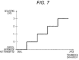
- Fig. 7 is a diagram illustrating an exemplary setting for a requesting level by the information processor 100 according to the first embodiment of the present technology.
- Fig. 7 illustrates the exemplary setting for a requesting level in accordance with a transmission data amount (transmission traffic amount). Further, in a graph of Fig. 7, a horizontal axis represents the transmission data amount (transmission traffic amount) and a vertical axis represents the requesting level.
- Fig. 7 illustrates an exemplary case where a range of the requesting level is set at four values from 0 to 3. Further, in the case where the transmission data amount is smaller than a threshold value, the control information is prevented from being transmitted. Further, in the case where the transmission data amount is larger than the threshold value, the value of the requesting level is increased in incremental steps based on the graph illustrated in Fig. 7.
- control unit 130 of the information processor 100 can determine the timing to transmit the control unit based on the transmission data amount (characteristic amount) acquired from the transmitting unit 110. For example, in the case where an amount of the transmission data is larger than the threshold value as a reference, the control unit 130 transmits the control information, and in the case where the amount of the transmission data is smaller than the threshold value as the reference, the control unit 130 stops transmitting the control information.
- control unit 130 of the information processor 100 can set the requesting level of the information processor 100 based on the transmission data amount (characteristic amount) acquired from the transmitting unit 110.
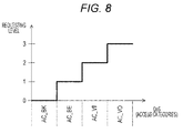
- Fig. 8 is a diagram illustrating an exemplary setting for the requesting level by the information processor 100 according to the first embodiment of the present technology.
- Fig. 8 is the exemplary setting for the requesting level in accordance with QoS of the transmission data (transmission traffic). Further, in a graph of Fig. 8, a horizontal axis represents the QoS of the transmission data (transmission traffic), and a vertical axis represents the requesting level. Further, Fig. 8 is an example of using an access category defined by IEEE 802.11 as the QoS.
- Fig. 8 illustrates an exemplary case where a range of the requesting level is set at four values from 0 to 3. Further, AC_BK (background), AC_BE (best effort), AC_VI (video), AC_VO (voice (sound)) are allocated to respective ranges of the requesting level.
- the control unit 130 of the information processor 100 can determine the timing to transmit the control information based on the QoS acquired from the transmitting unit 110. For example, in the case where the QoS of the transmission data is higher than a threshold value as a reference, the control unit 130 transmits the control information, and in the case where the QoS of the transmission data is lower than the threshold value as the reference, the control unit 130 stops transmitting the control information.
- control unit 130 of the information processor 100 can set the requesting level of the information processor 100 based on the QoS acquired from the transmitting unit 110.
- the requesting level may be set in consideration of both setting the requesting level based on the transmission data amount illustrated in Fig. 7 and setting the requesting level based on the QoS illustrated in Fig. 8.
- the control unit 130 of the information processor 100 can determine the timing to transmit the control information based on the transmission data amount acquired from the transmitting unit 110, and the QoS. Further, the control unit 130 of the information processor 100 can set the requesting level of the information processor 100 based on the transmission data amount acquired from the transmitting unit 110, and the QoS.
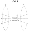
- Fig. 9 is a diagram illustrating an exemplary setting for the requesting level by the information processor 100 according to the first embodiment of the present technology.
- Fig. 9 illustrates the exemplary setting for the requesting level in the case where the information processor 100 transfer data from another information processor (namely, in the case where the information processor 100 functions as a relay node).
- Fig. 9 illustrates the example of using only a data amount in the case where the information processor 100 transfers the data from another information processor, instead of data when the information processor 100 is a destination or a source of transmission.
- Fig. 9 schematically illustrates receipt of data 401 to be transferred by the information processor 100 and transmission of the data 402 to be transferred by the information processor 100.
- the data is buffered by the information processor 100 In this case, throughput is decreased in an entire flow. Therefore, in the case where a difference between the throughput of the received data and the throughput of the transmitted data is large, the requesting level of the control information is increased. On the other hand, in the case where the difference is small, the requesting level of the control information is decreased.
- the requesting level may be set based on other information (such as occupancy rate of buffer capacity).
- the requesting level of the control information is increased.
- the requesting level of the control information is increased.
- the requesting level of the control information is decreased.
- a value weighted based on a data amount and QoS of the respective data may be set as the requesting level.
- control unit 130 can determine the timing to transmit the control information based on the transmitting/receiving information acquired from the transmitting unit 110 and the receiving unit 120 (for example, throughputs of the transmission data and received data and the transmission rates of the transmission data and the received data). Further, the control unit 130 can set the requesting level of the information processor 100 based on the transmitting/receiving information acquired from the transmitting unit 110 and the receiving unit 120.
- control unit 130 can determine the requesting level of the control information based on the data to be an object of transfer in the case of transferring the data of another information processor. For example, the control unit 130 can determine a requesting level of the control information based on a comparison result between throughput of the received data to be the object of transfer and throughput of the transmission data to be transferred. Further, the control unit 130 can determine the requesting level of the control information based on a comparison result between a transmission rate of the received data to be the object of transfer and a transmission rate of the transmission data to be transferred.
- FIG. 10 is a flowchart illustrating an exemplary transmission procedure in transmission processing by the information processor 100 according to the first embodiment of the present technology.
- the control unit 130 of the information processor 100 acquires transmitting/receiving information of the own device (Step S801).
- the control unit 130 acquires the transmitting/receiving information (for example, data amount of transmission data, QoS of transmission data, throughputs of transmission data and received data, transmission rates of transmission data and received data) from at least one of the transmitting unit 110 and the receiving unit 120.
- the control unit 130 determines a requesting level based on the acquired transmitting/receiving information (Step S802).
- the requesting level can be determined based on any one of the examples illustrated in Figs. 7 to 9.
- control unit 130 embeds the control information including the determined requesting level in a beacon (Step S803). Further, the control unit 130 embeds, in the beacon, the control information to be transmitted out of the control information related to another information processor (Step S803). For example, as illustrated in Fig. 4C, the respective control information (ID, transfer, requesting level) is embedded in the beacon.
- control unit 130 transmits the beacon embedded with the control information to an information processor present in the surrounding area (Step S804).
- Step S805 determines whether a finish command for transmission processing is provided. Then, in the case where the finish command for transmission processing is provided (Step S805), operation of the transmission processing is finished. On the other hand, in the case where there is no finish command for transmission processing (Step S805), the processing returns to Step S801.
- control unit 130 generates and transmits, based on a data transmitting state of the information processor 100, the control information to request the information processor present in the surrounding area so as to reduce transmission power.
- Fig. 11 is a diagram illustrating an exemplary setting for transmission power by the information processor 100 according to the first embodiment of the present technology.
- Fig. 11 illustrates the exemplary setting for the transmission power based on the number of received control information (namely, the number of information processors having transmitted the control information). Further, in a graph of Fig. 11, a horizontal axis represents the number of received control information, and a vertical axis represents a value of transmission power.
- control information For example, in the case where the number of received control information is many, it can be estimated that many information processors which transmit data are present in the surrounding area of the own device. Therefore, control is made to reduce the transmission power of the own device in order to reduce interference with the information processors present in the surrounding area.
- the number of the received control information is weighted in accordance with the requesting level, and transmission power may be set based on this weighted value.
- the transmission power can be set based on a value obtained by adding values in the requesting levels field included in all of the received control information.
- a threshold value is set, and the transmission power can be set based on the number of control information that has a value larger than the threshold value in the requesting level field.
- control unit 130 can control the transmission power based on the number of the received control information.
- Fig. 12 is a diagram illustrating an exemplary setting for transmission power by the information processor 100 according to the first embodiment of the present technology.
- Fig. 12 illustrates the exemplary setting for transmission power based on a value in the transfer field of the received control information. Further, in a graph of Fig. 12, a horizontal axis represents the number of information processors having the value 1 or more in the transfer field included in the received control information, and a vertical axis represents a value of the transmission power.
- control information For example, in the case where the number of received control information is many, it can be estimated that many information processors which transmit data are present in the surrounding area of the own device. Therefore, control is made to reduce the transmission power of the own device in order to reduce interference with the information processors present in the surrounding area.
- direct communication cannot be performed with an information processor which has the value of 1 or more in the transfer field included in the received control information (namely, the information processor located in two hops away). Due to this, a signal transmitted by the own device interferes with such information processors. Therefore, the transmission power of the own device is reduced in order to reduce interference with these information processors.
- a value obtained by performing weighting on the value in the transfer field included in the received control information may be also used.
- the transmission power can be set by ignoring the control information having the value of 2 or more in the transfer field, for example.
- “Exemplary Setting for Transmission Power by Performing Weighting in Accordance with Requesting Level” For example, assume the case where a requesting level field is set in the control information. In this case, the number of transfer of the received control information is weighted by the requesting level, and transmission power may be set based on this weighted value. For example, the transmission power can be set based on the value obtained by adding all of the requesting level of the control information which has the value 1 or more in the transfer field among all of the received control information. Further, for example, a threshold value is set, and the transmission power can be set by using only the control information that has a value larger than the threshold value in the requesting level field.
- control unit 130 can control the transmission power based on the number of transfer of the received control information.
- Example of Suppressing Frequent Change of Transmission Power As described above, a range where the information processor 100 can perform direct communication is varied by changing the transmission power. Therefore, even in the case where there is no change in a position or a transmitting state of each information processor, the value in the transfer field of the control information is changed. In this case, the setting value of the transmission power is frequently changed, and the system may become unstable. Therefore, the setting value of the transmission power can be prevented from being frequently changed by differently setting a setting value at the time of increasing the transmission power and a setting value at the time of reducing the transmission power. For example, the setting value at the time of increasing the transmission power can be set larger than the setting value at the time of reducing the transmission power. Thus, hysteresis can be provided in order to prevent frequent change of the value of the transmission power.
- FIG. 13 is a flowchart illustrating an exemplary procedure for setting the transmission power by the information processor 100 according to the first embodiment of the present technology.
- control unit 130 of the information processor 100 determines whether a beacon is received (Step S811). Then, in the case of not receiving any beacon, monitoring is continuously performed (Step S811).
- the control unit 130 extracts the control information included in the received beacon (Step S812). Next, the control unit 130 updates the held control information based on the extracted control information (Step S813).
- the control unit 130 unifies the control information having the same ID based on the value in the transfer field included in the control information having the same ID. More specifically, the control unit 130 compares the values in the transfer field included in the control information having the same ID, and determines the control information having a smallest value in the transfer field as the control information to be held.
- control unit 130 unifies the control information having the same ID based on the value in the transfer field included in the control information having the same ID in the same manner.
- the control unit 130 determines the transmission power of the own device based on the held control information (Step S814).
- the transmission power of the own device can be determined based on the examples illustrated in Figs. 11 and 12.
- control unit 130 performs control to change the transmission power of the own device to the determined transmission power (Step S815).
- Step S816 determines whether a finish command for transmission power setting processing is provided. Then, in the case where the finish command for transmission power setting processing is provided (Step S816), operation of the transmission power setting processing is finished. On the other hand, in the case where there is no finish command for the transmission power setting processing (Step S816), the processing returns to Step S811.
- control unit 130 can control the transmission power based on such control information.
- the example of controlling the transmission power per beacon cycle is illustrated in Fig. 13, but the transmission power may be controlled at different timing. Further, a cycle of controlling the transmission power may be changed as well.
- Second Embodiment> In a first embodiment of the present technology, examples of controlling transmission power based on received control information have been described. However, the transmission power may be controlled by using other information.
- a configuration of an information processor according to the second embodiment of the present technology is substantially same as information processors 100 to 105 illustrated in Figs. 1, 2, and so on. Therefore, as for components same as the first embodiment of the present technology, a description will be partly omitted by denoting the components by the reference signs same as the first embodiment of the present technology.
- transmission throughput As the transmitting information of the own device, reception power of a transmitting destination is reduced by reducing transmission power of the own device, thereby decreasing a transmission rate.
- transmission throughput may be decreased depending on availability of a channel. Therefore, in the case where the transmission throughput is not decreased even when the transmission power is reduced, control can be performed so as to further reduce the transmission power. Further, in this case, the transmission power may be reduced up to a level that the transmission rate does not become lower than the level considered as minimum necessary.
- control unit 130 can control the transmission power to be further reduced when the throughput of data transmission of the information processor 100 is not decreased in the case where the transmission power is reduced based on the control information.
- Example of Using QoS Next, an example of using QoS as the transmitting information of the own device will be described. For example, the example of using access categories according to IEEE 802.11 as the QoS will be described.
- control unit 130 can change control for the transmission power (e.g., stop and perform) based on the QoS of the transmission data of the information processor 100.
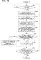
- Fig. 14 is a flowchart illustrating an exemplary procedure for setting the transmission power by the information processor 100 according to the second embodiment of the present technology. Note that Fig. 14 is partly modified from Fig. 13 and partly same as Fig. 13. More specifically, Steps S821 to S823 and S827 in Fig. 14 are same as Steps S811 to S813 and S815 in Fig. 13. Therefore, a part of the description for the same Steps will be omitted.
- the control unit 130 After updating the held control information (Step S823), the control unit 130 determines a candidate transmission power of the own device based on the held control information (Step S824). Note that a method of determining the candidate transmission power is same as the method of determining the transmission power in Fig. 13.
- control unit 130 acquires the transmitting information of the own device, and determines a transmission required condition (Step S825).
- the transmission throughput As the transmitting information, whether the transmission throughput is decreased or not is determined even when the transmission power is reduced. Further, in the case where the transmission throughput is not decreased even when the transmission power is reduced, the transmission required condition is determined so as to further reduce the transmission power.
- whether the transmission data has high importance or not is determined (for example, whether AC_VO, AC_VI or not). Then, in the case where the transmission data is the data having high importance, the transmission required condition is determined so as to stop controlling to reduce the transmission power. In contrast, in the case where the transmission data is the data having low importance (for example, AC_BE and AC_BK), the above-described control is performed for the transmission power.
- the control unit 130 determines whether the transmission power determined as the candidate satisfies the determined transmission required condition (Step S826). In the case where the transmission power determined as the candidate satisfies the determined transmission required condition (Step S826), the control unit 130 controls the transmission power of the own device to be the transmission power determined as the candidate (Step S827).
- the control unit 130 corrects the transmission power determined as the candidate such that the transmission power determined as the candidate satisfies the determined transmission required condition (Step S828). Further, the control unit 130 controls the transmission power of the own device to be the corrected transmission power (Step S828).
- the transmission power of the own device can be controlled based on the data transmitting states of the information processor present in the surrounding area and the own device. This can prevent decrease of throughput when the transmission power is reduced more than necessary. For example, in the case where an amount of data transmission by the information processor present in the surrounding area is little, the throughput of the own device can be improved by highly setting the transmission power of the own device. Further, in the case where the amount of data transmission of the information processor present in the surrounding area is large, interference can be reduced when needed by reducing the transmission power of the own device.
- control information to request an adjacent information processor so as to reduce the transmission power can be exchanged with the adjacent information processor based on the data transmitting state of the own device. This enables more optimal control for transmission power in accordance with the transmitting state of the adjacent information processor.
- a transmitting state of an information processor located at two hops away can be grasped. This can reduce interference with the information processors located at two or more hops away.
- the information processor having received such control information can control the transmission power based on the transmitting state of the information processor present in the surrounding area and the transmitting state of the own device. This can reduce interference with other information processors in a range without influencing data transmission of the own device.
- a configuration of the information processor according to the third embodiment of the present technology is substantially same as information processors 100 to 105 illustrated in Figs. 1, 2, and so on. Therefore, as for components same as the first embodiment of the present technology, a description will be partly omitted by denoting the components by the reference signs same as the first embodiment of the present technology.
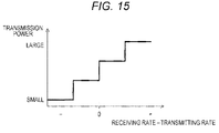
- Fig. 15 is a diagram illustrating an exemplary setting for the transmission power by the information processor 100 according to a third embodiment of the present technology.
- Fig. 15 illustrates the exemplary setting for transmission power based on a difference in transmission rate of the transferred data (difference between a transmission rate of received data and a transmission data of transmitted data).
- a horizontal axis represents a difference value in the transmission rate of the transferred data (difference value between the transmission rate of received data and the transmission data of transmitted data)
- a vertical axis represents a value of transmission power.
- the information processor 100 transfers data as a relay node (namely, in the case of relaying data).
- a relay node namely, in the case of relaying data.
- the relay node controls transmission power of the own device based on the difference.
- a control unit 130 of the information processor 100 calculates a difference value in the transmission rate of the transferred data (difference value between a transmission rate of received data (receiving rate) and transmission rate of transmission data (transmitting rate)). Then, in the case where the transmitting rate is larger than the receiving rate, the control unit 130 performs setting to reduce the transmission power. In contrast, in the case where the transmitting rate is smaller than the receiving rate, the control unit 130 performs setting to increase the transmission power.
- Fig. 15 is the example of setting the transmission power regardless of presence of the control information.
- the transmission power may be set only based on the difference value in the transmission rate of the transferred data (difference value between the receiving rate and the transmitting rate), and also such setting may be used by combining a method of setting the transmission power based on the control information.
- FIG. 16 is a flowchart illustrating an exemplary procedure for setting the transmission power by an information processor 100 according to the third embodiment of the present technology.
- control unit 130 of the information processor 100 acquires information related to transmitting/receiving states of the transferred data (transmission rate of received data (receiving rate) and transmission rate of transmission data (transmitting rate)) (Step S831).
- control unit 130 determines whether the transmission rate of the transmission data (transmitting rate) is larger than the transmission rate of the received data (receiving rate) (Steps S832 and S834).
- the control unit 130 performs setting to reduce the transmission power (Step S833).
- the control unit 130 performs setting to increase the transmission power (Step S835).
- Step S836 determines whether a finish command for relay processing is provided. Then, in the case where the finish command for relay processing is provided (Step S836), operation of the relay processing is finished. On the other hand, in the case where there is no finish command for relay processing (Step S836), the processing returns to Step S831.
- control unit 130 can control the transmission power based on a comparison result between the received data be an object of transfer to another information processor and the transmission data to be transferred. For example, the control unit 130 can control the transmission power so as to reduce the difference between the transmission rate of the received data to be the object of transfer and the transmission rate of the transmission data to be transferred.
- the information processor which relays data between other information processors can control the transmission power so as to reduce the difference between the transmission rate of the received data and the transmission rate of the transmitted data. This can reduce interference with another information processor without decreasing throughput of the data transfer.
- the transmission power in a radio communication network can be suitably controlled.
- radio waves can be effectively utilized by controlling the transmission power in the radio communication network. This prevents reduction of a transmission opportunity of the information processor present in the surrounding area, and also can suppress interference with the information processor present in the surrounding area. As a result, the transmission power can be prevented from being reduced more than necessary. Further, throughput in the entire network can be improved.
- the information processors 100 to 105 may be implemented as a mobile terminal such as a smartphone, a tablet personal computer (PC), a notebook PC, a mobile game terminal, or a digital camera, as a fixed terminal such as a television receiver, a printer, a digital scanner, or a network storage, and as an in-vehicle terminal such as a car navigation device.
- a mobile terminal such as a smartphone, a tablet personal computer (PC), a notebook PC, a mobile game terminal, or a digital camera
- a fixed terminal such as a television receiver, a printer, a digital scanner, or a network storage
- an in-vehicle terminal such as a car navigation device.
- the information processors 100 to 105 may be implemented as a terminal that performs machine-to-machine (M2M) communication (also referred to as a machine type communication (MTC) terminal) such as a smart meter, an automatic vending machine, a remote monitoring device, and a point of sale (POS) terminal.
- M2M machine-to-machine
- MTC machine type communication
- POS point of sale
- the information processors 100 to 105 may be a radio communication module mounted on the mentioned terminals (for example, an integrated circuit module formed of one die).
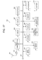
- Fig. 17 is a block diagram illustrating an exemplary schematic configuration of a smartphone 900 to which the technology according to the present disclosure can be applied.
- the smartphone 900 includes a processor 901, a memory 902, a storage 903, an external connection interface 904, a camera 906, a sensor 907, a microphone 908, an input device 909, a display device 910, a speaker 911, a radio communication interface 913, an antenna switch 914, an antenna 915, a bus 917, a battery 918, and an auxiliary controller 919.
- the processor 901 may be, for example, a central processing unit (CPU) or a system on chip (SoC), and controls functions of an application layer and other layers of the smartphone 900.
- the memory 902 includes random access memory (RAM) and read only memory (ROM), and stores a program to be executed by the processor 901, and data.
- the storage 903 may include a storage medium such as semiconductor memory or a hard disk.
- the external connection interface 904 is an interface to connect an external device such as a memory card or a universal serial bus (USB) device to the smartphone 900.
- the camera 906 includes, for example, an imaging device such as a charge coupled device (CCD) or a complementary metal oxide semiconductor (CMOS), and forms a captured image.
- the sensor 907 may include, for example, a group of sensors such as a positioning sensor, a gyro sensor, a geomagnetic sensor, and an acceleration sensor.
- the microphone 908 converts a sound received in the smartphone 900 to an audio signal.
- the input device 909 includes, for example, a touch sensor to detect a touch on a screen of the display device 910, a keypad, a keyboard, a button, a switch, or the like, and receives operation or information input from a user.
- the display device 910 includes a screen such as a liquid crystal display (LCD) or an organic light emitting diode (OLED), and displays an output image of the smartphone 900.
- the speaker 911 converts, to a sound, the audio signal output from the smartphone 900.
- the radio communication interface 913 supports one or more of the radio LAN standards such as IEEE 802.11a, 11b, 11g, 11n, 11ac, and 11ad, and performs radio communication.
- the radio communication interface 913 can perform communication with another device via a radio communication LAN access point in an infrastructure mode. Further, the radio communication interface 913 can perform direct communication with another device in a direct communication mode such as an ad hoc mode or Wi-Fi Direct. Meanwhile, in the Wi-Fi Direct, one out of two terminals operates as an access point different from the ad hoc mode, but communication is directly performed between the terminals.
- the radio communication interface 913 may typically include a baseband processor, a radio frequency (RF) circuit, a power amplifier, and so on.
- RF radio frequency
- the radio communication interface 913 may be one-chip module in which a memory to store a communication control program, a processor to execute the program, and a related circuit are integrated.
- the radio communication interface 913 may support other kinds of radio communication systems, such as a short distance radio communication system, a proximity radio communication system, or a cellular communication system in addition to the radio LAN system.
- the antenna switch 914 switches a connecting destination of the antenna 915 among a plurality of circuits (for example, circuits for different radio communication systems) included in the radio communication interface 913.
- the antenna 915 includes a single antenna element or multiple antenna elements (for example, a plurality of antenna elements constituting a MIMO antenna), and is used for the radio communication interface 913 to transmit and receive radio signals.
- the smartphone 900 is not limited to the example in Fig. 17, and may include a plurality of antennas (for example, antenna for radio LAN, antenna for a proximity radio communication system, etc.).
- the antenna switch 914 may be omitted from the configuration of the smartphone 900.
- the bus 917 connects a processor 901, a memory 902, a storage 903, an external connection interface 904, a camera 906, a sensor 907, a microphone 908, an input device 909, a display device 910, a speaker 911, a radio communication interface 913, and an auxiliary controller 919 one another.
- a battery 918 supplies power to respective blocks of the smartphone 900 illustrated in Fig. 17 via a power supply lines partly shown in dashed lines in the drawing.
- the auxiliary controller 919 activates minimum necessary functions of the smartphone 900 in a sleep mode, for example.
- a control unit 130 described using Fig. 2 may also be mounted on the radio communication interface 913. Further, at least a part of functions may be mounted on the processor 901 or the auxiliary controller 919.
- the processor 901 may also work as a radio access point (software AP) by executing an access point function at an application level. Further, the radio communication interface 913 may also have the radio access point function.
- Fig. 18 is a block diagram illustrating an exemplary schematic configuration of a car navigation device 920 to which the technology according to the present disclosure is applicable.
- the car navigation device 920 includes a processor 921, a memory 922, a global positioning system (GPS) module 924, a sensor 925, a data interface 926, a content player 927, a storage medium interface 928, an input device 929, a display device 930, a speaker 931, a radio communication interface 933, an antenna switch 934, an antenna 935, and a battery 938.
- GPS global positioning system
- the processor 921 may be, for example, a CPU or a SoC, and controls a navigation function and other functions of the car navigation device 920.
- the memory 922 includes RAM and ROM, and stores a program executed by the processor 921 and data.
- the GPS module 924 measures a position (latitude, longitude, and altitude) of the car navigation device 920 by using a GPS signal received from a GPS satellite.
- the sensor 925 may include a group of sensors such as gyro sensor, a geomagnetic sensor, and an atmospheric pressure sensor.
- the data interface 926 is connected to, for example, an in-vehicle network 941 via a terminal not illustrated, and acquires data generated on a vehicle side such as vehicle speed data.
- the content player 927 reproduces the content stored in a storage medium (for example, CD or DVD) inserted into the storage medium interface 928.
- the input device 929 includes, for example, a touch sensor to detect a touch on a screen of the display device 930, a button, a switch, or the like, and receives operation or information input from a user.
- the display device 930 includes a screen such as an LCD or an OLED display, and displays a navigation function or an image of the reproduced content.
- the speaker 931 outputs the navigation function or a sound of the reproduced content.
- the radio communication interface 933 supports one or more of the radio LAN standards such as IEEE 802.11a, 11b, 11g, 11n, 11ac, and 11ad, and performs radio communication.
- the radio communication interface 933 can perform communication with another device via a radio communication LAN access point in an infrastructure mode. Further, the radio communication interface 933 can perform direct communication with another device in a direct communication mode such as an ad hoc mode or Wi-Fi Direct.
- the radio communication interface 933 may typically include a baseband processor, an RF circuit, a power amplifier, and so on.
- the radio communication interface 933 may be one-chip module in which a memory to store a communication control program, a processor to execute the program, and a related circuit are integrated.
- the radio communication interface 933 may support other kinds of radio communication systems such as a short distance radio communication system, a proximity radio communication system, or a cellular communication system in addition to the radio LAN system.
- the antenna switch 934 switches a connecting destination of the antenna 935 among a plurality of circuits included in the radio communication interface 933.
- the antenna 935 includes a single antenna element or multiple antenna elements, and is used for the radio communication interface 933 to transmit and receive radio signals.
- the car navigation device 920 is not limited to the example of Fig. 18, and may include a plurality of antennas.
- the antenna switch 934 may be omitted from the configuration of the car navigation device 920.
- the battery 938 supplies power to respective blocks of the car navigation device 920 illustrated in Fig. 18 via a power supply lines partly shown in dashed lines in the drawing. Further, the battery 938 accumulates power supplied from the vehicle side.
- a control unit 130 described using Fig. 2 may also be mounted on the radio communication interface 933. Further, at least a part of the functions may also be mounted on the processor 921.
- the technology according to the present disclosure may be implemented as an in-vehicle system (or vehicle) 940 including one or more blocks of the above-described car navigation device 920, the in-vehicle network 941, and a vehicle-side module 942.
- the vehicle-side module 942 generates vehicle-side data such as a vehicle speed, an engine rotary speed, and failure information, and outputs the generated data to the in-vehicle network 941.
- the processing procedures described in the above-described embodiments may be handled as a method including a series of procedures or may be handled as a program for causing a computer to execute the series of procedures and as a recording medium storing the program.
- a recording medium a compact disc (CD), a mini disc (MD), and a digital versatile disk (DVD), a memory card, and a Blu-ray disc (registered trademark) can be used, for example.
- An electronic device including: circuitry configured to receive information transmitted from at least one other electronic device; determine a transmission power of the electronic device based on the information; determine whether the transmission power satisfies a predetermined condition; and update the transmission power in transmitting data to the at least one other electronic device in a case that transmission power does not satisfy the predetermined condition.
- the electronic device of (1) wherein the circuitry is configured to identify a number of the other electronic devices based on the information.
- the circuitry is configured to determine the transmission power of the electronic device based on the number of other electronic devices.
- the circuitry is configured to determine the transmission power to be a first value in a case that the number of other electronic devices is below a threshold number and a second value in a case that the number of electronic devices is greater than the threshold number, the first value being greater than the second value.
- the information indicates a transmission power characteristic of the at least one other electronic device.
- the circuitry is configured to determine the transmission power of the electronic device based on the transmission power characteristic of the at least one other electronic device.
- the circuitry is configured to communicate with the at least one other electronic device via an ad hoc network formed between the electronic device and the at least one other electronic device.
- the electronic device of (9), wherein the circuitry is configured to detect a new electronic device to the ad hoc network based on information transmitted from the new electronic device.
- the electronic device of (10), wherein the circuitry is configured to update the transmission power based on the detection of the new electronic device.
- the ad hoc network is a mesh network.
- CSMA carrier sense multiple access
- the circuitry is configured to not change the transmission power in a case that the amount of data to be transmitted by the electronic device is less than the threshold value.
- the circuitry is configured to update the transmission power by increasing the transmission power in a case that the amount of data to be transmitted by the electronic device is greater than the threshold value.
- the electronic device of (16), wherein the circuitry is configured to update the transmission power by increasing the transmission power in a stepwise manner based on the amount of data to be transmitted by the electronic device.
- the circuitry is configured to control transmitting a control signal indicating the updated transmission power to the at least one other electronic device.
- the predetermined condition corresponds to whether a Quality of Service (QoS) level of data to be transmitted by the electronic device is less than a threshold QoS level.
- QoS Quality of Service
- the circuitry is configured to not change the transmission power in a case that the QoS level of data to be transmitted by the electronic device is less than the threshold QoS level.
- circuitry is configured to update the transmission power by increasing the transmission power in a case that the QoS level of data to be transmitted by the electronic device is greater than the threshold QoS level.
- circuitry is configured to update the transmission power by increasing the transmission power in a stepwise manner for each QoS level the data to be transmitted is greater than the threshold QoS level.
- circuitry is configured to control transmitting a control signal indicating the updated transmission power to the at least one other electronic device.
- the predetermined condition corresponds to whether a difference between a transmission rate of data received at the electronic device and a transmission rate of data transmitted from the electronic device is less than a threshold value.
- the circuitry is configured to not change the transmission power in a case that the difference between the transmission rate of data received at the electronic device and the transmission rate of data transmitted from the electronic device is less than the threshold value.
- the circuitry is configured to update the transmission power by increasing the transmission power in a case that the difference between the transmission rate of data received at the electronic device and the transmission rate of data transmitted from the electronic device is greater than the threshold value.
- circuitry is configured to control transmitting a control signal indicating the updated transmission power to the at least one other electronic device.
- a method performed by an electronic device including: receiving, by a communication interface of the electronic device, information transmitted from at least one other electronic device; determining, by circuitry of the electronic device, a transmission power of the electronic device based on the information; determining, by the circuitry, whether the transmission power satisfies a predetermined condition; and determining, by the circuitry, an update to the transmission power that is applied in transmitting data to the at least one other electronic device in a case that transmission power does not satisfy the predetermined condition.
- One or more non-transitory computer-readable media including computer program instructions, which when executed by an electronic device, cause the electronic device to: receive information transmitted from at least one other electronic device; determine a transmission power of the electronic device based on the information; determine whether the transmission power satisfies a predetermined condition; and update the transmission power in transmitting data to the at least one other electronic device in a case that transmission power does not satisfy the predetermined condition.
- An electronic device including: circuitry configured to identify a first transmission rate of data received at the electronic device; identify a second transmission rate of data transmitted from the electronic device; and determine a transmission power for transmitting date from the electronic device based on a difference between the first transmission rate and the second transmission rate.
- An electronic device including: circuitry configured to generate, based on a data transmitting state of the electronic device, control information to request at least one other electronic device to reduce transmission power; and transmit the control information to the at least one other electronic device. (35) The electronic device according to (34), wherein the circuitry is configured to transmit the control information in a case that an amount of transmission data is larger than a threshold value. (36) The electronic device according to (34), wherein the circuitry is configured to transmit the control information in the case that a quality of service (QoS) of transmission data is higher than a threshold value.
- QoS quality of service
- the electronic device according to any of (34) to (36), wherein the circuitry is configured to determine a level of power reduction of the other electronic device to be indicated in the control information based on a characteristic of received data that is to be transmitted from the electronic device. (38) The electronic device according to (37), wherein the circuitry is configured to determine a level of power reduction of the other electronic device to be indicated in the control information based on a comparison between a rate at which the data is received at the electronic device and a rate at which the information is transmitted from the electronic device. (39) An information processor including a control unit configured to control transmission power based on a data transmitting state of an information processor present in a surrounding area.
- control information is generated by the information processor present in the surrounding area based on a data transmitting state of the information processor, and the control unit controls the transmission power based on the control information in the case of receiving the control information to request the information processor present in the surrounding area of the information processor so as to reduce the transmission power.
- control unit controls the transmission power based on the number of the received control information.
- control unit controls the transmission power based on the number of transfer of the received control information.
- the information processor according to any one of (39) to (45), wherein the control unit controls the transmission power based on a data transmitting state of the information processor present in the surrounding area and a data transmitting state of an own device.
- An information processor including a control unit configured to control transmission power based on a comparison result between received data to be an object of transfer to another information processor and corresponding transmission data to be transferred.
- the control unit controls the transmission power so as to reduce a difference between the transmission rate of the received data to be the object of transfer and the transmission rate of the transmission data to be transferred.
- An information processing method including controlling transmission power based on a data transmitting state of an information processor present in a surrounding area.
- An information processing method including generating and transmitting, based on a data transmitting state of an own device, control information to request an information processor present in a surrounding area so as to reduce transmission power.
Landscapes
- Engineering & Computer Science (AREA)
- Computer Networks & Wireless Communication (AREA)
- Signal Processing (AREA)
- Quality & Reliability (AREA)
- Mobile Radio Communication Systems (AREA)
- Telephone Function (AREA)
- Telephonic Communication Services (AREA)
Abstract
An electronic device that receives information transmitted from at least one other electronic device; determines a transmission power of the electronic device based on the information; determines whether the transmission power satisfies a predetermined condition; and determines an update to the transmission power that is applied in transmitting data to the at least one other electronic device in a case that transmission power does not satisfy the predetermined condition.
Description
The present technology relates to an information processor. More specifically, the present technology relates to an information processor and an information processing method to handle information related to radio communication, and a program causing a computer to execute the method.
In the related art, there is a radio communication technology in which various kinds of data are exchanged by utilizing radio communication. For instance, there is a proposed technology of a communication method to autonomously interconnect with an information processor present in a surrounding area (for example, ad hoc communication and an ad hoc network).
Additionally, for example, there is a proposed radio multi-hop communication device in which a node constituting a radio multi-hop network exchanges a state of received radio with an adjacent node by transmitting and receiving a packet of transmission power control (refer to Patent Literature 1, for example). In the case where there is any radio wave reaching the adjacent node with which no direct communication route is provided, the radio multi-hop communication device reduces transmission power down to a level not to destabilize communication with another adjacent node with which a direct communication route is provided.
According to the above-described technology, radio interference can be reduced by reducing the transmission power. However, there may be a risk that the transmission power is reduced more than necessary because transmitting condition of the adjacent node is not considered. Accordingly, appropriately setting transmission power by considering the transmitting condition of the adjacent node is important.
The present technology is made in view of the above situation, and directed to appropriately setting the transmission power.
According to one embodiment, the disclosure is directed to an electronic device that receives information transmitted from at least one other electronic device; determines a transmission power of the electronic device based on the information; determines whether the transmission power satisfies a predetermined condition; and determines an update to the transmission power that is applied in transmitting data to the at least one other electronic device in a case that transmission power does not satisfy the predetermined condition.
The electronic device may be configured to identify a number of the other electronic devices based on the information and determine the transmission power of the electronic device based on the number of other electronic devices. The electronic may be configured to determine the transmission power to be a first value in a case that the number of other electronic devices is below a threshold number and a second value in a case that the number of electronic devices is greater than the threshold number, the first value being greater than the second value.
The information may indicate at least one of a transmission power characteristic of the at least one other electronic device or a transmitting state of the at least one other electronic device. And the electronic device may be configured to determine the transmission power of the electronic device based on the transmission power characteristic of the at least one other electronic device.
The electronic device may be configured to control a communication interface to transmit a notification indicating the new transmission power.
The electronic device may be configured to communicate with the at least one other electronic device via an ad hoc network formed between the electronic device and the at least one other electronic device.
The electronic device may be configured to detect a new electronic device to the ad hoc network based on information transmitted from the new electronic device, and update the transmission power based on the detection of the new electronic device. The ad hoc network may be a mesh network that applies carrier sense multiple access (CSMA).
The predetermined condition may correspond to whether an amount of data to be transmitted by the electronic device is less than a threshold value.
The electronic device may be configured to not change the transmission power in a case that the amount of data to be transmitted by the electronic device is less than the threshold value. The electronic device may be configured to update the transmission power by increasing the transmission power in a case that the amount of data to be transmitted by the electronic device is greater than the threshold value. The electronic device may be configured to update the transmission power by increasing the transmission power in a stepwise manner based on the amount of data to be transmitted by the electronic device. The electronic device may be configured to control transmitting a control signal indicating the updated transmission power to the at least one other electronic device.
The predetermined condition may correspond to whether a Quality of Service (QoS) level of data to be transmitted by the electronic device is less than a threshold QoS level.
The electronic device may be configured to not change the transmission power in a case that the QoS level of data to be transmitted by the electronic device is less than the threshold QoS level. The electronic device may be configured to update the transmission power by increasing the transmission power in a case that the QoS level of data to be transmitted by the electronic device is greater than the threshold QoS level. The electronic device may be configured to update the transmission power by increasing the transmission power in a stepwise manner for each QoS level the data to be transmitted is greater than the threshold QoS level. The electronic device may be configured to control transmitting a control signal indicating the updated transmission power to the at least one other electronic device.
The predetermined condition may correspond to whether a difference between a transmission rate of data received at the electronic device and a transmission rate of data transmitted from the electronic device is less than a threshold value.
The electronic device may be configured to not change the transmission power in a case that the difference between the transmission rate of data received at the electronic device and the transmission rate of data transmitted from the electronic device is less than the threshold value. The electronic device may be configured to update the transmission power by increasing the transmission power in a case that the difference between the transmission rate of data received at the electronic device and the transmission rate of data transmitted from the electronic device is greater than the threshold value. The electronic device may be configured to control transmitting a control signal indicating the updated transmission power to the at least one other electronic device.
The electronic device may be configured to identify a number of hops that the information traversed prior to arriving at the electronic device. The electronic device may be configured to determine the transmission power of the electronic device based on the number of hops that the information traversed prior to arriving at the electronic device. The electronic device may be configured to determine the transmission power to be a first value in a case that the number of hops is below a threshold number and a second value in a case that the number of hops is greater than the threshold number, the first value being greater than the second value.
According to one embodiment, the disclosure is directed to a method performed by an electronic device, the method including: receiving, by a communication interface of the electronic device, information transmitted from at least one other electronic device; determining, by circuitry of the electronic device, a transmission power of the electronic device based on the information; determining, by the circuitry, whether the transmission power satisfies a predetermined condition; and determining, by the circuitry, an update to the transmission power that is applied in transmitting data to the at least one other electronic device in a case that transmission power does not satisfy the predetermined condition.
According to one embodiment, the disclosure is directed to one or more non-transitory computer-readable media including computer program instructions, which when executed by an electronic device, cause the electronic device to: receive information transmitted from at least one other electronic device; determine a transmission power of the electronic device based on the information; determine whether the transmission power satisfies a predetermined condition; and update transmission power in transmitting data to the at least one other electronic device in a case that transmission power does not satisfy the predetermined condition.
According to one embodiment, the disclosure is directed to an electronic device including: circuitry configured to identify a first transmission rate of data received at the electronic device; identify a second transmission rate of data transmitted from the electronic device; and determine a transmission power for transmitting date from the electronic device based on a difference between the first transmission rate and the second transmission rate.
According to one embodiment, the disclosure is directed to an electronic device comprising: circuitry configured to generate, based on a data transmitting state of the electronic device, control information to request at least one other electronic device to reduce transmission power; and transmit the control information to the at least one other electronic device.
According to the present technology, there is an excellent effect that the transmission power can be appropriately set. Note that the effects recited herein are not limited thereto and may be any effect disclosed in the present disclosure.
Embodiments to implement the present technology will be described below (hereinafter referred to as the embodiments). A description will be given in the following order.
1. First embodiment (example of controlling transmission power based on a data transmitting state of an information processor present in a surrounding area)
2. Second embodiment (example of controlling transmission power based on a data transmitting state of an information processor present in a surrounding area and a data transmitting state of an own device)
3. Third embodiment (example of controlling transmission power based on a comparison result between received data to be an object of transfer to another information processor and the transmission data to be transferred)
4. Application examples
<1. First Embodiment>
"Exemplary Configuration of Communication System"
Fig. 1 is a diagram illustrating an exemplary system configuration of acommunication system 10 according to a first embodiment of the present technology. The communication system 10 is an example of a radio communication system configured by an information processor which confirms an occupied state of media (such as channel and resource) prior to transmission, and performs transmission in the case where the media is cleared.
"Exemplary Configuration of Communication System"
Fig. 1 is a diagram illustrating an exemplary system configuration of a
The communication system 10 includes information processors 100 to 105. In Fig. 1, a relation between information processors that can directly communicate is indicated by arrows of dotted lines.
Each of the information processors (devices) constituting the communication system 10 is, for example, a portable information processor and a fixed information processor having a radio communication function. Meanwhile, the portable information processor is a radio communication device such as a smartphone, a mobile phone, and a tablet terminal, and the fixed information processor is an information processor such as a printer and a personal computer. Also, for example, each of the electronic devices can be an electronic device such as a sensor, a television, a projector, a hard disk recorder, a speaker, a microphone, an access point, a personal computer (PC), or a display. Also, for example, each of the electronic devices can be an electronic device such as a drone, a medical device, a surgical device, a patient tracking monitor, gaming device, a Blu-ray disc player, a printer, a light with a sensor, an automatic door, a security device, or a disaster prevention device. Also, for example, each of the electronic devices is a tablet, a smartphone, a photo frame, a refrigerator, an air conditioner, an air cleaner, a vacuum cleaner (such as self-propelled vacuum cleaner), a laundry machine, a microwave, a toaster, a ventilation fan, or a radio.
Here, as a communication method to autonomously interconnect with an information processor (node) present in the surrounding area, ad hoc communication, an ad hoc network, etc. are known. In such a network, each information processor and an information processor present in the surrounding area can communicate each other without relying on a master station. More specifically, control information is exchanged between the information processors adjacent to each other, and communication with another information processor can be performed by autonomously forming a network. Therefore, according to the embodiment of the present technology, a description will be given by exemplifying the ad hoc network as a communication method to autonomously interconnect with the information processor present in the surrounding area. Note that the master station is a control device that performs centralized control like an access point of a radio local area network (LAN) and a base station of mobile phones.
In the ad hoc network, when a new information processor is added in the surrounding area, the new information processor can also freely participate in the network. For example, among the respective information processors in Fig. 1, assume the case where only the information processor 100 and the information processor 101 can participate in the ad hoc network. In this case, assume that an information processor 102 and an information processor 103 are sequentially added. In this case, a range covered by the network can be increased in accordance with addition of the respective information processors (information processors present in the surrounding area). More specifically, the range covered by the network can be increased by sequentially adding the information processor 102 and information processor 103.
Here, the respective information processors can also transfer information exchanged with other information processors in a bucket brigade manner in addition to autonomously interconnecting with the information processors present in the surrounding area. In other words, the respective information processors not only transmit and receive data of the own device (traffic) but also can relay data which other information processors transmit and receive (traffic).
For example, assume that the information processor 102 can directly communicate with the information processors 100, 101, 103, but cannot directly communicate with the information processors 104, 105 for the reason, for example, that the radio waves cannot reach.
Even in the case where direct communication cannot be thus performed, the information processors 100, 101, 103 which can directly communicate with the information processor 102 can transfer data of the information processor 102 to the information processor 105. Accordingly, by thus transferring the data, the information processor 102 and the information processor 105 which cannot directly communicating with the information processor 102 can mutually exchange information via the information processors 100, 101, 103. More specifically, the information processor 102 cannot directly communicate with the information processor 105, but can communicate with the information processor 105 by the information processor 100 or the like relaying the data of the information processor 102. In the same manner, the information processor 102 can communicate with the information processor 104.
The method in which data transfer is thus transferred by a relay node (namely, bucket brigade) to communicate with a distant information processor is called multi-hop relay. Further, the network performing the multi-hop is generally known as a mesh network. Also, as a technology configuring the mesh network, the standards such as Institute of Electrical and Electronic Engineers (IEEE) 802.11s-2011 are known.
An exemplary configuration of the information processor constituting such an ad hoc network or a mesh network is illustrated in Fig. 2. Further, the communication system 10 is an exemplary network in which a plurality of information processors is mutually connected by the plurality of information processors performing one-to-one radio communication.
"Exemplary Configuration of Information Processor"
Fig. 2 is a block diagram illustrating an exemplary internal configuration of theinformation processor 100 according to the first embodiment of the present technology. Note that a description will be given only for the internal configuration of the information processor 100 here, and a description for those of other information processors (information processors 101 to 105) will be omitted for being same as the information processor 100.
Fig. 2 is a block diagram illustrating an exemplary internal configuration of the
The information processor 100 includes a transmitting unit 110, a receiving unit 120, a control unit 130, a memory 140, and an antenna 150. Note that only the components related to radio communication will be mainly described in Fig. 2, and a description and illustration for other components will be omitted.
The transmitting unit 110 includes a channel encoder 111, a modulator 112, and a radio frequency (RF) transmitter 113.
When data to be transmitted is received, the channel encoder 111 encodes the data to be transmitted based on control of the control unit 130 and also applies error correction encoding, and then outputs, to the modulator 112, the data applied with the error correction encoding.
The modulator 112 demodulates, based on control of the control unit 130, the data applied with the error correction encoding by the channel encoder 111, and outputs the modulated data (modulation signal) to the RF transmitter 113.
The RF transmitter 113 amplifies, based on control of the control unit 130, the modulation signal output from the modulator 112, and transmits the amplified demodulation signal via the antenna 150. For example, the RF transmitter 113 amplifies the modulation signal output from the modulator 112 to power corresponding to an indication value of transmission power output from the control unit 130, and transmits the amplified demodulation signal via the antenna 150.
The receiving unit 120 includes an RF receiver 121, a demodulator 122, and a channel decoder 123.
The RF receiver 121 converts, based on control of the control unit 130, a signal received via the antenna 150 (received signal) to a baseband signal, and outputs the baseband signal to the demodulator 122.
The demodulator 122 demodulates, based on control of the control unit 130, the baseband signal output from the RF receiver 121, and outputs the demodulated signal to the channel decoder 123.
The channel decoder 123 applies, based on control of the control unit 130, error correction and decoding to the signal demodulated by the demodulator 122, and outputs the data applied with error correction and decoding.
For example, the transmitting unit 110 and the receiving unit 120 can perform radio communication by millimeter-wave communication (such as 60 GHz), a radio LAN of 900 MHz/2.4 GHz/5 GHz, and an ultra wide band (UWB). Further, for example, the transmitting unit 110 and the receiving unit 120 can perform radio communication by visible light communication and near field communication (NFC).
Meanwhile, the transmitting unit 110 and the receiving unit 120 may perform radio communication using radio waves (electromagnetic waves), and may also perform radio communication using a medium other than radio waves (for example, radio communication using a magnetic field).
The control unit 130 controls respective units of the information processor 100 based on a control program stored in the memory 140. For example, the control unit 130 applies signal processing to the information transmitted and received. Further, the control unit 130 is implemented by a central processing unit (CPU), for example.
Furthermore, the control unit 130 controls transmission power based on a characteristic amount output from the transmitting unit 110 and the receiving unit 120 (for example, transmitting/receiving information of the own device). For example, the control unit 130 generates an indication value of transmission power, and outputs the indication value of transmission power to the RF transmitter 113 based on the characteristic amount output from the transmitting unit 110 and the receiving unit 120.
For example, the control unit 130 generates and transmits, based on a data transmitting state of the information processor 100, the control information to request an information processor present in the surrounding area so as to reduce the transmission power. Further, for example, the control unit 130 controls transmission power based on the data transmitting state of the information processor present in the surrounding area.
For example, in the case of receiving the control information, the control unit 130 transfers the control information to another information processor until the number of transfer of the control information reaches a setting value (e.g., 1).
The memory 140 is a memory to store various kinds of information. For example, various kinds of information needed for the information processor 100 to perform predetermined operation (for example, control program) are stored in the memory 140. Further, the control information received by the information processor 100 is stored in the memory 140 per information processor (for example, control information illustrated in Fig. 4C).
Here, assume a network related to a radio access method based on carrier sense multiple access (CSMA) represented by IEEE 802.11. Especially, assume the network (e.g., mesh network) in which a plurality of information processors using the same channel is present in the surrounding area.
For example, in the access method based on the CSMA, the number of transmitting opportunity is reduced in accordance with a data amount transmitted on the same channel (traffic amount). For example, assume the case where communication is performed with an information processor B in the case where an information processor A exists adjacent (very close) and a path loss in a space with the information processor A is considerably smaller than a path loss in a space with the other information processor B. In this case, when a signal of the information processor A is received, transmission to the information processor B cannot be performed. In other words, when the data amount is increased, an interference amount given to the adjacent information processor is increased, and there may be a risk in which a band used by the adjacent information processor is limited and transmission opportunity of the adjacent information processor is reduced.
Additionally, assume the case where a plurality of information processors performing transmission and reception on the same channel is present adjacent. In this case, when the own device performs data transmission, such data transmission interferes with the information processors other than the information processor to which the data is transmitted. Therefore, in the access method based on the CSMA, the data transmission by the own device may limit the transmission opportunity of other information processors. For example, in the case where a transmitting environment of a link performing data transmission is good, data transmission is performed with transmission power more than necessary, thereby reducing the transmission opportunity of another information processor. In other words, data transmission by the own device may increase unnecessary interference.
Therefore, the transmission power may be controlled in accordance with a transmitting condition of the own device. For example, assume the case where the transmission power of the own device is reduced when the information processor present in the surrounding area does not transmit data. In this case, interference with another information processor is reduced, and transmission opportunity of another information processor can be increased while influence is not given to another information processor because another information processor does not transmit data. However, in this case, a transmission data rate of the own device is lowered, and throughput is reduced.
Further, the transmission power may also be controlled in accordance with the number of adjacent information processors and the number of the information processors present in the surrounding area (nodes next to an adjacent node) detected by an adjacent information processor, and in accordance with distances from these information processors. However, in the case of thus controlling the transmission power, there may be a possibility that the transmission power is reduced more than necessary because the transmitting condition of another information processor cannot be grasped.
Thus, even in the case of controlling the transmission power of the own device in accordance with the transmitting condition of the own device, the number of information processors present in the surrounding area, and the distance therebetween, the transmission power may be reduced more than necessary, and there may be a risk that throughput of an entire system is decreased. In other words, system capacity such as the throughput of the entire system is not necessarily increased.
Further, in the mesh network or the like, data transferred by another information processor may be transferred. In this case, throughput of a flow is determined by a transmission rate of a path which is to be the lowest transmission rate. For example, in the case where there is a difference between the transmission rate of the transmitted data and the transmission rate of the received data among the data to be transferred, the path having the high transmission rate does not contribute to improving the throughput of the flow. Therefore, in the case of not controlling the transmission power, the transmission power more than necessary is used for transmission at a high transmission rate, and there may be a risk that interference with the information processor present in the surrounding area is increased. In other words, there may be a risk that unnecessary interference is increased due to imbalance between the received data (receiving traffic) and the transmission data (transmission traffic) of the information processor which relays the data (relay node). Examples thereof are illustrated in Figs. 3A to 3C.
"Exemplary Transmission Power Control"
Figs. 3A to 3C are diagrams illustrating comparative examples of transmission power control which can be performed in the communication system according to the first embodiment of the present technology. In Figs. 3A to 3C, exemplary relations between a mesh network formed ofmesh information processors 21 to 24 and a mesh network formed of information processors 31 to 33 are illustrated. Further, in Figs. 3A to 3C, a relation in which the information processors can perform direct communication is indicated by arrows of dotted lines. Further, a communicable range of the information processor 21 is schematically illustrated by ellipses 41 to 43 of dotted lines.
Figs. 3A to 3C are diagrams illustrating comparative examples of transmission power control which can be performed in the communication system according to the first embodiment of the present technology. In Figs. 3A to 3C, exemplary relations between a mesh network formed of
In Figs. 3A to 3C, illustrated are the comparative examples in the case of reducing interference and increasing transmission opportunity by controlling the transmission power in the mesh network (IEEE 802.11s, for example).
Fig. 3A illustrates an exemplary network configuration in the case of not controlling the transmission power. Further, Fig. 3A illustrates the exemplary case where the information processor 21 and the information processor 31 respectively perform data communication with adjacent information processors.
According to the example in Fig. 3A, the information processor 31 receives transmission data from the information processor 21 because the information processor 31 is included in the communicable range of the information processor 21 (ellipse 41 indicated by a dotted line). Thus, when the information processor 31 receives the transmission data from the information processor 21, data transmission is needed to be stopped until a channel is cleared. Therefore, the transmission opportunity of the information processor 31 is reduced.
Fig. 3B illustrates an exemplary network configuration in the case of controlling the transmission power. Further, Fig. 3B illustrates an exemplary case where the information processor 21 and the information processor 31 respectively perform data communication with adjacent information processors.
As illustrated in Fig. 3B, the communicable range of the information processor 21 (ellipse 42 indicated by a dotted line) becomes smaller by reducing the transmission power of the information processor 21. Therefore, data from the information processor 21 hardly reaches the information processor 31. By this, the information processor 31 can transmit data of the own device and the transmission opportunity thereof is increased regardless of performance of data transmission by the information processor 21. Further, interference power given to the information processors 32, 33 from the information processor 21 is also reduced, thereby improving communicating conditions of the information processors 32, 33.
Here, assume the case where there is a difference in transmission power between the information processor 21 and the information processor 31. In this case, decrease of the transmission opportunity of the information processor 31 can be prevented by the information processor 21 controlling performance of signal detection.
However, a transmitting rate of the data transmitted by the information processor 21 is also reduced by the information processor 21 reducing the transmission power. For example, when the information processor 31 performs data transmission, throughput and the like of the entire network is increased due to increase of the transmission opportunity of the information processor 31. On the other hand, when there is no data transmission performed by the information processor 31, the throughput of the entire network is reduced by a decreased amount of the transmitting rate of the information processor 21.
Fig. 3C illustrates an exemplary network configuration in the case of controlling transmission power based on transmitting states of the information processors present in the surrounding area. Further, Fig. 3C illustrates the exemplary case where the information processor 31 does not perform data communication with the adjacent information processors.
As illustrated in Fig. 3C, in the case where there is no data transmission by the information processor 31, the information processor 21 increases transmission power. By this, the transmission rate of the information processor 21 can be increased, and the throughput can be improved. Thus, when the information processors present in the surrounding area do not perform data transmission, the transmission power of the own device is increased. When the information processors present in the surrounding area perform data transmission, the transmission power of the own device is reduced. As a result, transmission opportunity of the information processors present in the surrounding area can be increased.
"Exemplary Formats of Control Information (Control Signal)"
Figs. 4A to 4C are diagrams illustrating exemplary formats of control information (control signal) exchanged between respective information processors constituting thecommunication system 10 according to the first embodiment of the present technology.
Figs. 4A to 4C are diagrams illustrating exemplary formats of control information (control signal) exchanged between respective information processors constituting the
Here, the respective information processors constituting the communication system 10 exchange packet-form signals at the time of communication. Further, each of the information processors constituting the communication system 10 notifies the information processors present in the surrounding area of the transmitting state of the own device. Therefore, control information (control signal) is transmitted at regular intervals (or at necessary timing). The control information is used as a notification to request another information processor so as to reduce the transmission power.
Further, since each of the information processors constituting the communication system 10 notifies the plurality of information processors of the transmitting state of the own device, preferably, the control information is transmitted in a broadcast frame. Therefore, according to the first embodiment of the present technology, provided is an example of superimposing the control information on a beacon frame (exemplary implementation on the beacon frame) in order to avoid increase of a new control frame. Further, Figs. 4A to 4C illustrate examples of using the beacon frame based on IEEE 802.11. Note that the beacon frame is one of a management frame.
Further, information other than the beacon may be used as well. For example, a Probe request used in broadcast transmission and scanning may be used.
Fig. 4A is an exemplary media access control (MAC) frame format of the management frame. A MAC header is from a frame control field to a high throughput (HT) control field. Further, an Information Element of the beacon frame is stored in a frame body field. In the Information Element, information such as a time stamp, a beacon cycle, and a service set identifier (SSID) is stored.
Further, in the Information Element, a Vendor-specific element which can be uniquely implemented by a vendor is prepared. This exemplary format is illustrated in Fig. 4B.
Fig. 4B illustrates an exemplary format of a Vendor-specific element. In other words, the format of the Vendor-specific element illustrated in Fig. 4B is stored in a part of a frame body field illustrated in Fig. 4A.
Further, according to the first embodiment of the present technology, the control information (control signal) is stored in the Vendor-specific content 200 illustrated in Fig. 4B. An exemplary format of the control information is illustrated in Fig. 4C.
In Fig. 4C, the exemplary format of the control information (control signal) is illustrated. The control information is formed of ID fields 201, 211, transfer fields 202, 212, and requesting level fields 203, 213. One in each of the ID field, transfer field, and requesting level field are stored per information processor. For example, the control information (ID field, transfer field, and requesting level field) related to the own device is arranged first, and then the control information (ID field, transfer field, and requesting level field) related to other devices is arranged next. Further, in the case where there is a plurality of other information processors to which the control information is to be transmitted, the control information of the corresponding number (the number of information processors to which the control information is to be transmitted) is sequentially arranged. Note that the order of arrangement can be determined in accordance with a predetermined rule (for example, order of receipt).
In the ID fields 201, 211, IDs to identify the information processors in the network (for example, MAC address) are stored. Note that according to the first embodiment of the present technology, a description will be given defining the IDs of the information processors 100 to 105 as 0 to 5 to simplify the description.
In the transfer fields 202, 212, the number of times corresponding control information has been transferred is stored. For example, 0 is stored in the transfer field 202 of the own device in the control information transmitted by the own device. Further, 1 is added to the value of the transfer field every time transfer is performed.
In the requesting level fields 203, 213, stored are values corresponding to requesting levels in order to ask the information processors present in the surrounding area to reduce the transmission power.
For example, in the case of requesting an information processor present in the surrounding area to reduce the transmission power by a large amount, or in the case of strongly requesting the same to reduce the transmission power, the value of the requesting level is increased. In contrast, in the case of not requesting so, the value of the requesting level is decreased. Further, a range of the value of the requesting level may be any of binary and multiple values. Note that the requesting level field may be omitted in the control information. In this case, for example, a receiving-side information processor can determine a requesting level based on presence of the requesting level field.
The information processor having received the control information illustrated in Fig. 4C adds the received control information to the beacon of the own device, and transmits the same. In this case, 1 is added to the value of the transfer field (e.g., transfer field 212 illustrated in Fig. 4C). Further, in the case where IDs included in the received control information are same as the IDs included in the control information received in the past (ID fields 201, 211 illustrated in Fig. 4C), the control information is unified. In this case, when the values of the transfer field are different, the control information having a smaller value in the transfer field is adopted. Here, in the case where an upper limit value of the number of transfer is preliminarily set and a value exceeds the upper limit value, the control information may be prevented from being transferred.
"Exemplary Control Information Transfer"
Figs. 5A and 5B are diagrams illustrating a flow of control information exchanged between the respective information processors constituting thecommunication system 10 according to the first embodiment of the present technology, and exemplary acquired control information. In Figs. 5A and 5B, the exemplary case where the information processors 100 to 105 are arranged based on a topology illustrated in Fig. 1.
Figs. 5A and 5B are diagrams illustrating a flow of control information exchanged between the respective information processors constituting the
Fig. 5A illustrates the flow in which the control information transmitted from the information processor 105 reaches the information processor 102 in the communication system 10.
Fig. 5B illustrates the exemplary control information acquired by the information processor 102 in the example of Fig. 5A.
As illustrated in Fig. 5A, the control information transmitted by the information processor 105 is transferred by the information processor 100, information processor 101, information processor 104, and information processor 103, and reaches the information processor 102. The flow of the control information is indicated by arrows 301 to 303 of thick lines.
Further, the information processor 102 receives the control information of the information processor 105 from each of the information processor 100, information processor 101, and information processor 103. In this case, as illustrated in Fig. 5B, the control information is held in a memory of the information processor 102 (corresponding to a memory 140 in Fig. 2).
In Fig. 5B, the control information which the information processor 102 received from the information processor 103 via the information processor 104 is shown in an upper row. Further, the control information which the information processor 102 received from the information processor 100 is shown in a middle row. Further, the control information which the information processor 102 received from the information processor 101 is shown in a lower row. In this case, each of the ID fields 311 indicates "5" representing the information processor 105. Further, the values in the transfer field 312 are 2, 1, and 1 respectively. More specifically, the control information in the upper row of Fig. 5B is 2 because the control information is received from the information processor 103 via the information processor 104. On the other hand, the control information in the middle row of Fig. 5B is 1 because the control information is received from the information processor 100 not via other information processors. In the same manner, the control information in the lower row of Fig. 5B is 1 because the control information is received from the information processor 101 not via other information processors. Thus, in the case where the values of the transfer field are different, the control information having the smaller value is adopted as described above. In other words, 1 is adopted.
Further, the information processor 102 transmits the control information related to the own device together with the received control information. In this case, the information processor 102 adds 1 to the value of the transfer field of the control information related to the information processor 105, and then transmits the same. More specifically, the information processor 102 stores "5" in the ID field as the control information related to the information processor 105, stores "2" in the transfer field, and stores a received requesting level in the requesting level as it is, and then transmits the control information.
Here, in the case where the network is formed of many information processors, the number of control information to be exchanged is increased. Further, since interference power is generally reduced as the number of transfer is increased, the transmitting information of the information processor having the large number of transfer becomes less important. Therefore, an upper limit of transfer of the control information may be provided. More specifically, in the case where the upper limit of the number of transfer is preliminarily set and the number of transfer exceeds the upper limit value, the control information can be prevented from being transferred. For example, in the case where the number of transfer is set at 1, the control information transmitted by adjacent information processors is only collected (i.e., information processors within two hops or less).
"Example of Held Control Information"
Fig. 6 is a diagram illustrating an example of held control information acquired by aninformation processor 102 according to the first embodiment of the present technology. In Fig. 6, an exemplary case where the information processors 100 to 105 are arranged based on the topology illustrated in Fig. 1.
Fig. 6 is a diagram illustrating an example of held control information acquired by an
For example, 1 is stored in the transfer field 322 as illustrated in Fig. 6 with respect to the information processor 105 corresponding to "5" in the ID 321. Further, 0 or 1 is stored in the transfer field 322 in the same manner with respect to other information processors.
Further, the control information is held in the same manner as for other information processors 100 to 104. Furthermore, each of the information processors 100 to 105 updates the held control information at regular intervals or predetermined timing. For example, the held control information can be updated at the timing of receiving a beacon. Further, the held information may be erased at regular intervals or predetermined timing. For example, the held control information can be erased at the timing when a predetermined time has elapsed from being held. By this, old control information can be suitably erased.
Thus, how many information processors according to the number of hops are present in the surrounding area can be easily grasped by confirming the value of the transfer field 322 (for example, an adjacent information processor and an information processor adjacent thereto).
"Exemplary Transmission Of Control Information"
As described above, the control information can be exchanged between the respective information processors constituting thecommunication system 10. Accordingly, an exemplary setting for conditions to transmit the control information (e.g., timing) and the requesting level will be described below. For example, in the following, concrete examples of transmitting states to be transmitted as the control information and an exemplary setting for a requesting level included in the control information will be described. Note that any one of those described below may be used, or a plurality thereof may be combined by performing weighting. Further, in the following, an example in which the information processor 100 generates and transmits the control information will be described.
As described above, the control information can be exchanged between the respective information processors constituting the
"Exemplary Transmission Based on Transmitting Data Amount (Traffic Amount)"
Fig. 7 is a diagram illustrating an exemplary setting for a requesting level by theinformation processor 100 according to the first embodiment of the present technology. Fig. 7 illustrates the exemplary setting for a requesting level in accordance with a transmission data amount (transmission traffic amount). Further, in a graph of Fig. 7, a horizontal axis represents the transmission data amount (transmission traffic amount) and a vertical axis represents the requesting level.
Fig. 7 is a diagram illustrating an exemplary setting for a requesting level by the
Fig. 7 illustrates an exemplary case where a range of the requesting level is set at four values from 0 to 3. Further, in the case where the transmission data amount is smaller than a threshold value, the control information is prevented from being transmitted. Further, in the case where the transmission data amount is larger than the threshold value, the value of the requesting level is increased in incremental steps based on the graph illustrated in Fig. 7.
Thus, the control unit 130 of the information processor 100 can determine the timing to transmit the control unit based on the transmission data amount (characteristic amount) acquired from the transmitting unit 110. For example, in the case where an amount of the transmission data is larger than the threshold value as a reference, the control unit 130 transmits the control information, and in the case where the amount of the transmission data is smaller than the threshold value as the reference, the control unit 130 stops transmitting the control information.
Further, the control unit 130 of the information processor 100 can set the requesting level of the information processor 100 based on the transmission data amount (characteristic amount) acquired from the transmitting unit 110.
"Exemplary Transmission Based on Quality of Service (QoS) of Transmitting Data (Traffic)"
Fig. 8 is a diagram illustrating an exemplary setting for the requesting level by theinformation processor 100 according to the first embodiment of the present technology. Fig. 8 is the exemplary setting for the requesting level in accordance with QoS of the transmission data (transmission traffic). Further, in a graph of Fig. 8, a horizontal axis represents the QoS of the transmission data (transmission traffic), and a vertical axis represents the requesting level. Further, Fig. 8 is an example of using an access category defined by IEEE 802.11 as the QoS.
Fig. 8 is a diagram illustrating an exemplary setting for the requesting level by the
Fig. 8 illustrates an exemplary case where a range of the requesting level is set at four values from 0 to 3. Further, AC_BK (background), AC_BE (best effort), AC_VI (video), AC_VO (voice (sound)) are allocated to respective ranges of the requesting level.
Thus, the control unit 130 of the information processor 100 can determine the timing to transmit the control information based on the QoS acquired from the transmitting unit 110. For example, in the case where the QoS of the transmission data is higher than a threshold value as a reference, the control unit 130 transmits the control information, and in the case where the QoS of the transmission data is lower than the threshold value as the reference, the control unit 130 stops transmitting the control information.
Further, the control unit 130 of the information processor 100 can set the requesting level of the information processor 100 based on the QoS acquired from the transmitting unit 110.
Note that the requesting level may be set in consideration of both setting the requesting level based on the transmission data amount illustrated in Fig. 7 and setting the requesting level based on the QoS illustrated in Fig. 8. In other words, the control unit 130 of the information processor 100 can determine the timing to transmit the control information based on the transmission data amount acquired from the transmitting unit 110, and the QoS. Further, the control unit 130 of the information processor 100 can set the requesting level of the information processor 100 based on the transmission data amount acquired from the transmitting unit 110, and the QoS.
"Exemplary Transmission Based on Data Throughput (Relay Node)"
Fig. 9 is a diagram illustrating an exemplary setting for the requesting level by theinformation processor 100 according to the first embodiment of the present technology. Fig. 9 illustrates the exemplary setting for the requesting level in the case where the information processor 100 transfer data from another information processor (namely, in the case where the information processor 100 functions as a relay node). Further, Fig. 9 illustrates the example of using only a data amount in the case where the information processor 100 transfers the data from another information processor, instead of data when the information processor 100 is a destination or a source of transmission.
Fig. 9 is a diagram illustrating an exemplary setting for the requesting level by the
Fig. 9 schematically illustrates receipt of data 401 to be transferred by the information processor 100 and transmission of the data 402 to be transferred by the information processor 100.
For example, in the case where throughput of the received data is larger than throughput of the transmitted data, the data is buffered by the information processor 100 In this case, throughput is decreased in an entire flow. Therefore, in the case where a difference between the throughput of the received data and the throughput of the transmitted data is large, the requesting level of the control information is increased. On the other hand, in the case where the difference is small, the requesting level of the control information is decreased.
Meanwhile, the example of using the throughput is illustrated in Fig. 9, but the requesting level may be set based on other information (such as occupancy rate of buffer capacity).
"Exemplary Transmission Based on Transmission Rate (Relay Node)"
Here, an example of using a transmission rate of data to be transferred will be described. In this example, same as Fig. 9, the example of handling only the information of data to be relayed.
Here, an example of using a transmission rate of data to be transferred will be described. In this example, same as Fig. 9, the example of handling only the information of data to be relayed.
For example, in the case where the transmission rate of the received data is larger than the transmission rate of the transmitted data, the requesting level of the control information is increased. In other words, in the case where a difference between the transmission rate of the received data and the transmission rate of the transmitted data is large, the requesting level of the control information is increased. On the other hand, in the case where the difference is small, the requesting level of the control information is decreased.
Meanwhile, in the case of transferring a plurality of data, a value weighted based on a data amount and QoS of the respective data may be set as the requesting level.
Thus, the control unit 130 can determine the timing to transmit the control information based on the transmitting/receiving information acquired from the transmitting unit 110 and the receiving unit 120 (for example, throughputs of the transmission data and received data and the transmission rates of the transmission data and the received data). Further, the control unit 130 can set the requesting level of the information processor 100 based on the transmitting/receiving information acquired from the transmitting unit 110 and the receiving unit 120.
Thus, the control unit 130 can determine the requesting level of the control information based on the data to be an object of transfer in the case of transferring the data of another information processor. For example, the control unit 130 can determine a requesting level of the control information based on a comparison result between throughput of the received data to be the object of transfer and throughput of the transmission data to be transferred. Further, the control unit 130 can determine the requesting level of the control information based on a comparison result between a transmission rate of the received data to be the object of transfer and a transmission rate of the transmission data to be transferred.
"Exemplary Operation of Information Processor"
Fig. 10 is a flowchart illustrating an exemplary transmission procedure in transmission processing by theinformation processor 100 according to the first embodiment of the present technology.
Fig. 10 is a flowchart illustrating an exemplary transmission procedure in transmission processing by the
First, the control unit 130 of the information processor 100 acquires transmitting/receiving information of the own device (Step S801). For example, the control unit 130 acquires the transmitting/receiving information (for example, data amount of transmission data, QoS of transmission data, throughputs of transmission data and received data, transmission rates of transmission data and received data) from at least one of the transmitting unit 110 and the receiving unit 120.
Subsequently, the control unit 130 determines a requesting level based on the acquired transmitting/receiving information (Step S802). For example, the requesting level can be determined based on any one of the examples illustrated in Figs. 7 to 9.
Next, the control unit 130 embeds the control information including the determined requesting level in a beacon (Step S803). Further, the control unit 130 embeds, in the beacon, the control information to be transmitted out of the control information related to another information processor (Step S803). For example, as illustrated in Fig. 4C, the respective control information (ID, transfer, requesting level) is embedded in the beacon.
Subsequently, the control unit 130 transmits the beacon embedded with the control information to an information processor present in the surrounding area (Step S804).
Next, the control unit 130 determines whether a finish command for transmission processing is provided (Step S805). Then, in the case where the finish command for transmission processing is provided (Step S805), operation of the transmission processing is finished. On the other hand, in the case where there is no finish command for transmission processing (Step S805), the processing returns to Step S801.
Thus, the control unit 130 generates and transmits, based on a data transmitting state of the information processor 100, the control information to request the information processor present in the surrounding area so as to reduce transmission power.
"Exemplary Setting For Transmission Power"
Next, an example in which an information processor that has received control information sets transmission power will be described. More specifically, the exemplary setting in which the information processor having collected the control information from the information processor present in the surrounding area controls the transmission power based on the collected control information will be described.
Next, an example in which an information processor that has received control information sets transmission power will be described. More specifically, the exemplary setting in which the information processor having collected the control information from the information processor present in the surrounding area controls the transmission power based on the collected control information will be described.
"Exemplary Setting for Transmission Power Based on Number of Received Control Information"
Fig. 11 is a diagram illustrating an exemplary setting for transmission power by theinformation processor 100 according to the first embodiment of the present technology. Fig. 11 illustrates the exemplary setting for the transmission power based on the number of received control information (namely, the number of information processors having transmitted the control information). Further, in a graph of Fig. 11, a horizontal axis represents the number of received control information, and a vertical axis represents a value of transmission power.
Fig. 11 is a diagram illustrating an exemplary setting for transmission power by the
For example, in the case where the number of received control information is many, it can be estimated that many information processors which transmit data are present in the surrounding area of the own device. Therefore, control is made to reduce the transmission power of the own device in order to reduce interference with the information processors present in the surrounding area.
"Exemplary Setting for Transmission Power by Performing Weighting in Accordance with Requesting Level"
For example, in the case where a requesting level field is set in the control information, the number of the received control information is weighted in accordance with the requesting level, and transmission power may be set based on this weighted value. For example, the transmission power can be set based on a value obtained by adding values in the requesting levels field included in all of the received control information. Further, for example, a threshold value is set, and the transmission power can be set based on the number of control information that has a value larger than the threshold value in the requesting level field.
For example, in the case where a requesting level field is set in the control information, the number of the received control information is weighted in accordance with the requesting level, and transmission power may be set based on this weighted value. For example, the transmission power can be set based on a value obtained by adding values in the requesting levels field included in all of the received control information. Further, for example, a threshold value is set, and the transmission power can be set based on the number of control information that has a value larger than the threshold value in the requesting level field.
Thus, the control unit 130 can control the transmission power based on the number of the received control information.
"Exemplary Setting for Transmission Power based on Number of Transfer of Received Control Information"
Fig. 12 is a diagram illustrating an exemplary setting for transmission power by theinformation processor 100 according to the first embodiment of the present technology. Fig. 12 illustrates the exemplary setting for transmission power based on a value in the transfer field of the received control information. Further, in a graph of Fig. 12, a horizontal axis represents the number of information processors having the value 1 or more in the transfer field included in the received control information, and a vertical axis represents a value of the transmission power.
Fig. 12 is a diagram illustrating an exemplary setting for transmission power by the
For example, in the case where the number of received control information is many, it can be estimated that many information processors which transmit data are present in the surrounding area of the own device. Therefore, control is made to reduce the transmission power of the own device in order to reduce interference with the information processors present in the surrounding area.
For example, direct communication cannot be performed with an information processor which has the value of 1 or more in the transfer field included in the received control information (namely, the information processor located in two hops away). Due to this, a signal transmitted by the own device interferes with such information processors. Therefore, the transmission power of the own device is reduced in order to reduce interference with these information processors.
Note that a value obtained by performing weighting on the value in the transfer field included in the received control information may be also used. For example, the transmission power can be set by ignoring the control information having the value of 2 or more in the transfer field, for example.
"Exemplary Setting for Transmission Power by Performing Weighting in Accordance with Requesting Level"
For example, assume the case where a requesting level field is set in the control information. In this case, the number of transfer of the received control information is weighted by the requesting level, and transmission power may be set based on this weighted value. For example, the transmission power can be set based on the value obtained by adding all of the requesting level of the control information which has thevalue 1 or more in the transfer field among all of the received control information. Further, for example, a threshold value is set, and the transmission power can be set by using only the control information that has a value larger than the threshold value in the requesting level field.
For example, assume the case where a requesting level field is set in the control information. In this case, the number of transfer of the received control information is weighted by the requesting level, and transmission power may be set based on this weighted value. For example, the transmission power can be set based on the value obtained by adding all of the requesting level of the control information which has the
Thus, the control unit 130 can control the transmission power based on the number of transfer of the received control information.
"Example of Suppressing Frequent Change of Transmission Power"
As described above, a range where theinformation processor 100 can perform direct communication is varied by changing the transmission power. Therefore, even in the case where there is no change in a position or a transmitting state of each information processor, the value in the transfer field of the control information is changed. In this case, the setting value of the transmission power is frequently changed, and the system may become unstable. Therefore, the setting value of the transmission power can be prevented from being frequently changed by differently setting a setting value at the time of increasing the transmission power and a setting value at the time of reducing the transmission power. For example, the setting value at the time of increasing the transmission power can be set larger than the setting value at the time of reducing the transmission power. Thus, hysteresis can be provided in order to prevent frequent change of the value of the transmission power.
As described above, a range where the
"Exemplary Operation of Information Processor"
Fig. 13 is a flowchart illustrating an exemplary procedure for setting the transmission power by theinformation processor 100 according to the first embodiment of the present technology.
Fig. 13 is a flowchart illustrating an exemplary procedure for setting the transmission power by the
First, the control unit 130 of the information processor 100 determines whether a beacon is received (Step S811). Then, in the case of not receiving any beacon, monitoring is continuously performed (Step S811).
In the case of receiving the beacon (Step S811), the control unit 130 extracts the control information included in the received beacon (Step S812). Next, the control unit 130 updates the held control information based on the extracted control information (Step S813). In this case, it is also assumed that a plurality of beacons is received and there are some control information having the same ID among the control information included in the plurality of beacons. In this case, the control unit 130 unifies the control information having the same ID based on the value in the transfer field included in the control information having the same ID. More specifically, the control unit 130 compares the values in the transfer field included in the control information having the same ID, and determines the control information having a smallest value in the transfer field as the control information to be held. Further, it is also assumed that there is control information having the same ID as the held control information among the control information included in the received beacon. In this case also, the control unit 130 unifies the control information having the same ID based on the value in the transfer field included in the control information having the same ID in the same manner.
Subsequently, the control unit 130 determines the transmission power of the own device based on the held control information (Step S814). For example, the transmission power of the own device can be determined based on the examples illustrated in Figs. 11 and 12.
Then, the control unit 130 performs control to change the transmission power of the own device to the determined transmission power (Step S815).
Next, the control unit 130 determines whether a finish command for transmission power setting processing is provided (Step S816). Then, in the case where the finish command for transmission power setting processing is provided (Step S816), operation of the transmission power setting processing is finished. On the other hand, in the case where there is no finish command for the transmission power setting processing (Step S816), the processing returns to Step S811.
Thus, in the case of receiving the control information generated by the information processor present in the surrounding area based on the data transmitting state of the information processor, the control unit 130 can control the transmission power based on such control information.
Meanwhile, the example of controlling the transmission power per beacon cycle is illustrated in Fig. 13, but the transmission power may be controlled at different timing. Further, a cycle of controlling the transmission power may be changed as well.
<2. Second Embodiment>
In a first embodiment of the present technology, examples of controlling transmission power based on received control information have been described. However, the transmission power may be controlled by using other information.
In a first embodiment of the present technology, examples of controlling transmission power based on received control information have been described. However, the transmission power may be controlled by using other information.
Accordingly, in a second embodiment of the present technology, exemplary control for the transmission power based on other information will be described (for example, transmitting information of an own device). Note that a configuration of an information processor according to the second embodiment of the present technology is substantially same as information processors 100 to 105 illustrated in Figs. 1, 2, and so on. Therefore, as for components same as the first embodiment of the present technology, a description will be partly omitted by denoting the components by the reference signs same as the first embodiment of the present technology.
"Example of Using Transmission Throughput"
First, an example of using transmission throughput as the transmitting information of the own device will be described. For example, reception power of a transmitting destination is reduced by reducing transmission power of the own device, thereby decreasing a transmission rate. In this case, transmission throughput may be decreased depending on availability of a channel. Therefore, in the case where the transmission throughput is not decreased even when the transmission power is reduced, control can be performed so as to further reduce the transmission power. Further, in this case, the transmission power may be reduced up to a level that the transmission rate does not become lower than the level considered as minimum necessary.
First, an example of using transmission throughput as the transmitting information of the own device will be described. For example, reception power of a transmitting destination is reduced by reducing transmission power of the own device, thereby decreasing a transmission rate. In this case, transmission throughput may be decreased depending on availability of a channel. Therefore, in the case where the transmission throughput is not decreased even when the transmission power is reduced, control can be performed so as to further reduce the transmission power. Further, in this case, the transmission power may be reduced up to a level that the transmission rate does not become lower than the level considered as minimum necessary.
Thus, the control unit 130 can control the transmission power to be further reduced when the throughput of data transmission of the information processor 100 is not decreased in the case where the transmission power is reduced based on the control information.
"Example of Using QoS"
Next, an example of using QoS as the transmitting information of the own device will be described. For example, the example of using access categories according to IEEE 802.11 as the QoS will be described.
Next, an example of using QoS as the transmitting information of the own device will be described. For example, the example of using access categories according to IEEE 802.11 as the QoS will be described.
For example, in the case of transmitting data having higher importance, such as AC_VO and AC_VI, control to reduce the transmission power is stopped. On the other hand, in the case of transmitting the data having low importance, such as AC_BE and AC_BK, the above-described control for the transmission power is performed.
Thus, the control unit 130 can change control for the transmission power (e.g., stop and perform) based on the QoS of the transmission data of the information processor 100.
"Exemplary Operation of Information Processor"
Fig. 14 is a flowchart illustrating an exemplary procedure for setting the transmission power by theinformation processor 100 according to the second embodiment of the present technology. Note that Fig. 14 is partly modified from Fig. 13 and partly same as Fig. 13. More specifically, Steps S821 to S823 and S827 in Fig. 14 are same as Steps S811 to S813 and S815 in Fig. 13. Therefore, a part of the description for the same Steps will be omitted.
Fig. 14 is a flowchart illustrating an exemplary procedure for setting the transmission power by the
After updating the held control information (Step S823), the control unit 130 determines a candidate transmission power of the own device based on the held control information (Step S824). Note that a method of determining the candidate transmission power is same as the method of determining the transmission power in Fig. 13.
Next, the control unit 130 acquires the transmitting information of the own device, and determines a transmission required condition (Step S825).
For example, in the case of using the transmission throughput as the transmitting information, whether the transmission throughput is decreased or not is determined even when the transmission power is reduced. Further, in the case where the transmission throughput is not decreased even when the transmission power is reduced, the transmission required condition is determined so as to further reduce the transmission power.
Additionally, for example, in the case of using the QoS as the transmitting information, whether the transmission data has high importance or not is determined (for example, whether AC_VO, AC_VI or not). Then, in the case where the transmission data is the data having high importance, the transmission required condition is determined so as to stop controlling to reduce the transmission power. In contrast, in the case where the transmission data is the data having low importance (for example, AC_BE and AC_BK), the above-described control is performed for the transmission power.
Subsequently, the control unit 130 determines whether the transmission power determined as the candidate satisfies the determined transmission required condition (Step S826). In the case where the transmission power determined as the candidate satisfies the determined transmission required condition (Step S826), the control unit 130 controls the transmission power of the own device to be the transmission power determined as the candidate (Step S827).
In the case where the transmission power determined as the candidate does not satisfy the determined transmission required condition (Step S826), the control unit 130 corrects the transmission power determined as the candidate such that the transmission power determined as the candidate satisfies the determined transmission required condition (Step S828). Further, the control unit 130 controls the transmission power of the own device to be the corrected transmission power (Step S828).
Thus, according to the embodiment of the present technology, the transmission power of the own device can be controlled based on the data transmitting states of the information processor present in the surrounding area and the own device. This can prevent decrease of throughput when the transmission power is reduced more than necessary. For example, in the case where an amount of data transmission by the information processor present in the surrounding area is little, the throughput of the own device can be improved by highly setting the transmission power of the own device. Further, in the case where the amount of data transmission of the information processor present in the surrounding area is large, interference can be reduced when needed by reducing the transmission power of the own device.
Further, the control information to request an adjacent information processor so as to reduce the transmission power can be exchanged with the adjacent information processor based on the data transmitting state of the own device. This enables more optimal control for transmission power in accordance with the transmitting state of the adjacent information processor.
Further, by transferring such control information, a transmitting state of an information processor located at two hops away (next to adjacent information processor) can be grasped. This can reduce interference with the information processors located at two or more hops away.
Further, the information processor having received such control information can control the transmission power based on the transmitting state of the information processor present in the surrounding area and the transmitting state of the own device. This can reduce interference with other information processors in a range without influencing data transmission of the own device.
<3. Third Embodiment>
In first and second embodiments of the present technology, examples of controlling transmission power based on received control information have been described. However, in the case of a relay node, transmission power may be controlled without using the control information.
In first and second embodiments of the present technology, examples of controlling transmission power based on received control information have been described. However, in the case of a relay node, transmission power may be controlled without using the control information.
Accordingly, in a third embodiment of the present technology, an example in which the relay node controls the transmission power without using the control information will be described. Note that a configuration of the information processor according to the third embodiment of the present technology is substantially same as information processors 100 to 105 illustrated in Figs. 1, 2, and so on. Therefore, as for components same as the first embodiment of the present technology, a description will be partly omitted by denoting the components by the reference signs same as the first embodiment of the present technology.
"Exemplary Transmission Power Setting Based on Difference of Transmission Rates"
Fig. 15 is a diagram illustrating an exemplary setting for the transmission power by theinformation processor 100 according to a third embodiment of the present technology. Fig. 15 illustrates the exemplary setting for transmission power based on a difference in transmission rate of the transferred data (difference between a transmission rate of received data and a transmission data of transmitted data). Further, in a graph of Fig. 15, a horizontal axis represents a difference value in the transmission rate of the transferred data (difference value between the transmission rate of received data and the transmission data of transmitted data), and a vertical axis represents a value of transmission power.
Fig. 15 is a diagram illustrating an exemplary setting for the transmission power by the
For example, assume the case where the information processor 100 transfers data as a relay node (namely, in the case of relaying data). In this case, as illustrated in Fig. 9, in the case where there is a difference between transmitting condition of the transferred data and receiving condition of the transferred data, throughput in an entire flow can be improved by reducing the difference. Therefore, in such a case, the relay node controls transmission power of the own device based on the difference.
For example, a control unit 130 of the information processor 100 calculates a difference value in the transmission rate of the transferred data (difference value between a transmission rate of received data (receiving rate) and transmission rate of transmission data (transmitting rate)). Then, in the case where the transmitting rate is larger than the receiving rate, the control unit 130 performs setting to reduce the transmission power. In contrast, in the case where the transmitting rate is smaller than the receiving rate, the control unit 130 performs setting to increase the transmission power.
Note that Fig. 15 is the example of setting the transmission power regardless of presence of the control information. However, the transmission power may be set only based on the difference value in the transmission rate of the transferred data (difference value between the receiving rate and the transmitting rate), and also such setting may be used by combining a method of setting the transmission power based on the control information.
"Exemplary Operation of Information Processor"
Fig. 16 is a flowchart illustrating an exemplary procedure for setting the transmission power by aninformation processor 100 according to the third embodiment of the present technology.
Fig. 16 is a flowchart illustrating an exemplary procedure for setting the transmission power by an
First, the control unit 130 of the information processor 100 acquires information related to transmitting/receiving states of the transferred data (transmission rate of received data (receiving rate) and transmission rate of transmission data (transmitting rate)) (Step S831).
Subsequently, the control unit 130 determines whether the transmission rate of the transmission data (transmitting rate) is larger than the transmission rate of the received data (receiving rate) (Steps S832 and S834).
In the case where the transmitting rate is larger than the receiving rate (Step S832), the control unit 130 performs setting to reduce the transmission power (Step S833).
In the case where the transmission rate of the transmission data (transmitting rate) is smaller than the transmission rate of the received data (receiving rate) (Step S834), the control unit 130 performs setting to increase the transmission power (Step S835).
Next, the control unit 130 determines whether a finish command for relay processing is provided (Step S836). Then, in the case where the finish command for relay processing is provided (Step S836), operation of the relay processing is finished. On the other hand, in the case where there is no finish command for relay processing (Step S836), the processing returns to Step S831.
Thus, the control unit 130 can control the transmission power based on a comparison result between the received data be an object of transfer to another information processor and the transmission data to be transferred. For example, the control unit 130 can control the transmission power so as to reduce the difference between the transmission rate of the received data to be the object of transfer and the transmission rate of the transmission data to be transferred.
Thus, according to the third embodiment of the present technology, the information processor which relays data between other information processors (relay node) can control the transmission power so as to reduce the difference between the transmission rate of the received data and the transmission rate of the transmitted data. This can reduce interference with another information processor without decreasing throughput of the data transfer.
Thus, according to the embodiment of the present technology, the transmission power in a radio communication network can be suitably controlled. Further, radio waves can be effectively utilized by controlling the transmission power in the radio communication network. This prevents reduction of a transmission opportunity of the information processor present in the surrounding area, and also can suppress interference with the information processor present in the surrounding area. As a result, the transmission power can be prevented from being reduced more than necessary. Further, throughput in the entire network can be improved.
<4. Modified Examples>
The technology according to the present disclosure can be applied to various kinds of products. For example, theinformation processors 100 to 105 may be implemented as a mobile terminal such as a smartphone, a tablet personal computer (PC), a notebook PC, a mobile game terminal, or a digital camera, as a fixed terminal such as a television receiver, a printer, a digital scanner, or a network storage, and as an in-vehicle terminal such as a car navigation device. Further, the information processors 100 to 105 may be implemented as a terminal that performs machine-to-machine (M2M) communication (also referred to as a machine type communication (MTC) terminal) such as a smart meter, an automatic vending machine, a remote monitoring device, and a point of sale (POS) terminal. Moreover, the information processors 100 to 105 may be a radio communication module mounted on the mentioned terminals (for example, an integrated circuit module formed of one die).
The technology according to the present disclosure can be applied to various kinds of products. For example, the
"4-1. First Application Example"
Fig. 17 is a block diagram illustrating an exemplary schematic configuration of asmartphone 900 to which the technology according to the present disclosure can be applied. The smartphone 900 includes a processor 901, a memory 902, a storage 903, an external connection interface 904, a camera 906, a sensor 907, a microphone 908, an input device 909, a display device 910, a speaker 911, a radio communication interface 913, an antenna switch 914, an antenna 915, a bus 917, a battery 918, and an auxiliary controller 919.
Fig. 17 is a block diagram illustrating an exemplary schematic configuration of a
The processor 901 may be, for example, a central processing unit (CPU) or a system on chip (SoC), and controls functions of an application layer and other layers of the smartphone 900. The memory 902 includes random access memory (RAM) and read only memory (ROM), and stores a program to be executed by the processor 901, and data. The storage 903 may include a storage medium such as semiconductor memory or a hard disk. The external connection interface 904 is an interface to connect an external device such as a memory card or a universal serial bus (USB) device to the smartphone 900.
The camera 906 includes, for example, an imaging device such as a charge coupled device (CCD) or a complementary metal oxide semiconductor (CMOS), and forms a captured image. The sensor 907 may include, for example, a group of sensors such as a positioning sensor, a gyro sensor, a geomagnetic sensor, and an acceleration sensor. The microphone 908 converts a sound received in the smartphone 900 to an audio signal. The input device 909 includes, for example, a touch sensor to detect a touch on a screen of the display device 910, a keypad, a keyboard, a button, a switch, or the like, and receives operation or information input from a user. The display device 910 includes a screen such as a liquid crystal display (LCD) or an organic light emitting diode (OLED), and displays an output image of the smartphone 900. The speaker 911 converts, to a sound, the audio signal output from the smartphone 900.
The radio communication interface 913 supports one or more of the radio LAN standards such as IEEE 802.11a, 11b, 11g, 11n, 11ac, and 11ad, and performs radio communication. The radio communication interface 913 can perform communication with another device via a radio communication LAN access point in an infrastructure mode. Further, the radio communication interface 913 can perform direct communication with another device in a direct communication mode such as an ad hoc mode or Wi-Fi Direct. Meanwhile, in the Wi-Fi Direct, one out of two terminals operates as an access point different from the ad hoc mode, but communication is directly performed between the terminals. The radio communication interface 913 may typically include a baseband processor, a radio frequency (RF) circuit, a power amplifier, and so on. The radio communication interface 913 may be one-chip module in which a memory to store a communication control program, a processor to execute the program, and a related circuit are integrated. The radio communication interface 913 may support other kinds of radio communication systems, such as a short distance radio communication system, a proximity radio communication system, or a cellular communication system in addition to the radio LAN system. The antenna switch 914 switches a connecting destination of the antenna 915 among a plurality of circuits (for example, circuits for different radio communication systems) included in the radio communication interface 913. The antenna 915 includes a single antenna element or multiple antenna elements (for example, a plurality of antenna elements constituting a MIMO antenna), and is used for the radio communication interface 913 to transmit and receive radio signals.
Note that the smartphone 900 is not limited to the example in Fig. 17, and may include a plurality of antennas (for example, antenna for radio LAN, antenna for a proximity radio communication system, etc.). In this case, the antenna switch 914 may be omitted from the configuration of the smartphone 900.
The bus 917 connects a processor 901, a memory 902, a storage 903, an external connection interface 904, a camera 906, a sensor 907, a microphone 908, an input device 909, a display device 910, a speaker 911, a radio communication interface 913, and an auxiliary controller 919 one another. A battery 918 supplies power to respective blocks of the smartphone 900 illustrated in Fig. 17 via a power supply lines partly shown in dashed lines in the drawing. The auxiliary controller 919 activates minimum necessary functions of the smartphone 900 in a sleep mode, for example.
In the smartphone 900 illustrated in Fig. 17, a control unit 130 described using Fig. 2 may also be mounted on the radio communication interface 913. Further, at least a part of functions may be mounted on the processor 901 or the auxiliary controller 919.
Meanwhile, in the smartphone 900, the processor 901 may also work as a radio access point (software AP) by executing an access point function at an application level. Further, the radio communication interface 913 may also have the radio access point function.
"4-2. Second Application Example"
Fig. 18 is a block diagram illustrating an exemplary schematic configuration of acar navigation device 920 to which the technology according to the present disclosure is applicable. The car navigation device 920 includes a processor 921, a memory 922, a global positioning system (GPS) module 924, a sensor 925, a data interface 926, a content player 927, a storage medium interface 928, an input device 929, a display device 930, a speaker 931, a radio communication interface 933, an antenna switch 934, an antenna 935, and a battery 938.
Fig. 18 is a block diagram illustrating an exemplary schematic configuration of a
The processor 921 may be, for example, a CPU or a SoC, and controls a navigation function and other functions of the car navigation device 920. The memory 922 includes RAM and ROM, and stores a program executed by the processor 921 and data.
The GPS module 924 measures a position (latitude, longitude, and altitude) of the car navigation device 920 by using a GPS signal received from a GPS satellite. The sensor 925 may include a group of sensors such as gyro sensor, a geomagnetic sensor, and an atmospheric pressure sensor. The data interface 926 is connected to, for example, an in-vehicle network 941 via a terminal not illustrated, and acquires data generated on a vehicle side such as vehicle speed data.
The content player 927 reproduces the content stored in a storage medium (for example, CD or DVD) inserted into the storage medium interface 928. The input device 929 includes, for example, a touch sensor to detect a touch on a screen of the display device 930, a button, a switch, or the like, and receives operation or information input from a user. The display device 930 includes a screen such as an LCD or an OLED display, and displays a navigation function or an image of the reproduced content. The speaker 931 outputs the navigation function or a sound of the reproduced content.
The radio communication interface 933 supports one or more of the radio LAN standards such as IEEE 802.11a, 11b, 11g, 11n, 11ac, and 11ad, and performs radio communication. The radio communication interface 933 can perform communication with another device via a radio communication LAN access point in an infrastructure mode. Further, the radio communication interface 933 can perform direct communication with another device in a direct communication mode such as an ad hoc mode or Wi-Fi Direct. The radio communication interface 933 may typically include a baseband processor, an RF circuit, a power amplifier, and so on. The radio communication interface 933 may be one-chip module in which a memory to store a communication control program, a processor to execute the program, and a related circuit are integrated. The radio communication interface 933 may support other kinds of radio communication systems such as a short distance radio communication system, a proximity radio communication system, or a cellular communication system in addition to the radio LAN system. The antenna switch 934 switches a connecting destination of the antenna 935 among a plurality of circuits included in the radio communication interface 933. The antenna 935 includes a single antenna element or multiple antenna elements, and is used for the radio communication interface 933 to transmit and receive radio signals.
Note that the car navigation device 920 is not limited to the example of Fig. 18, and may include a plurality of antennas. In this case, the antenna switch 934 may be omitted from the configuration of the car navigation device 920.
The battery 938 supplies power to respective blocks of the car navigation device 920 illustrated in Fig. 18 via a power supply lines partly shown in dashed lines in the drawing. Further, the battery 938 accumulates power supplied from the vehicle side.
In the car navigation device 920 illustrated in Fig. 18, a control unit 130 described using Fig. 2 may also be mounted on the radio communication interface 933. Further, at least a part of the functions may also be mounted on the processor 921.
Further, the technology according to the present disclosure may be implemented as an in-vehicle system (or vehicle) 940 including one or more blocks of the above-described car navigation device 920, the in-vehicle network 941, and a vehicle-side module 942. The vehicle-side module 942 generates vehicle-side data such as a vehicle speed, an engine rotary speed, and failure information, and outputs the generated data to the in-vehicle network 941.
Note that the above-described embodiments are examples in order to embody the present technology, and the matters in the embodiments have a corresponding relationship with invention-specific matters in the scope of claims respectively. In the same manner, the matters in the embodiments and the invention-specific matters in the scope of claims denoted by the same names have corresponding relationship respectively. However, the present technology is not limited to the embodiments, and various modifications of the embodiments can be embodied in the scope of the present technology without departing from the spirit of the present technology.
The processing procedures described in the above-described embodiments may be handled as a method including a series of procedures or may be handled as a program for causing a computer to execute the series of procedures and as a recording medium storing the program. As the recording medium, a compact disc (CD), a mini disc (MD), and a digital versatile disk (DVD), a memory card, and a Blu-ray disc (registered trademark) can be used, for example.
Note that the effects recited in the present specification are examples and not limited thereto, and that other effects also may be provided.
Additionally, the present technology can also be configured as below.
(1) An electronic device including:
circuitry configured to
receive information transmitted from at least one other electronic device;
determine a transmission power of the electronic device based on the information;
determine whether the transmission power satisfies a predetermined condition; and
update the transmission power in transmitting data to the at least one other electronic device in a case that transmission power does not satisfy the predetermined condition.
(2) The electronic device of (1), wherein
the circuitry is configured to identify a number of the other electronic devices based on the information.
(3) The electronic device of (2), wherein
the circuitry is configured to determine the transmission power of the electronic device based on the number of other electronic devices.
(4) The electronic device of any of (2) to (3), wherein
the circuitry is configured to determine the transmission power to be a first value in a case that the number of other electronic devices is below a threshold number and a second value in a case that the number of electronic devices is greater than the threshold number, the first value being greater than the second value.
(5) The electronic device of any of (1) to (4), wherein
the information indicates a transmission power characteristic of the at least one other electronic device.
(6) The electronic device of any of (1) to (5), wherein
the information indicates a transmitting state of the at least one other electronic device.
(7) The electronic device of (5), wherein
the circuitry is configured to determine the transmission power of the electronic device based on the transmission power characteristic of the at least one other electronic device.
(8) The electronic device of any of (1) to (7), wherein
the circuitry is configured to control a communication interface to transmit a notification indicating the new transmission power.
(9) The electronic device of any of (1) to (8), wherein
the circuitry is configured to communicate with the at least one other electronic device via an ad hoc network formed between the electronic device and the at least one other electronic device.
(10) The electronic device of (9), wherein
the circuitry is configured to detect a new electronic device to the ad hoc network based on information transmitted from the new electronic device.
(11) The electronic device of (10), wherein
the circuitry is configured to update the transmission power based on the detection of the new electronic device.
(12) The electronic device of (9), wherein
the ad hoc network is a mesh network.
(13) The electronic device of (9), wherein
the ad hock network is a mesh network that applies carrier sense multiple access (CSMA).
(14) The electronic device of any of (1) to (13), wherein
the predetermined condition corresponds to whether an amount of data to be transmitted by the electronic device is less than a threshold value.
(15) The electronic device of (14), wherein
the circuitry is configured to not change the transmission power in a case that the amount of data to be transmitted by the electronic device is less than the threshold value.
(16) The electronic device of (14), wherein
the circuitry is configured to update the transmission power by increasing the transmission power in a case that the amount of data to be transmitted by the electronic device is greater than the threshold value.
(17) The electronic device of (16), wherein
the circuitry is configured to update the transmission power by increasing the transmission power in a stepwise manner based on the amount of data to be transmitted by the electronic device.
(18) The electronic device of (16), wherein
the circuitry is configured to control transmitting a control signal indicating the updated transmission power to the at least one other electronic device.
(19) The electronic device of any of (1) to (18), wherein
the predetermined condition corresponds to whether a Quality of Service (QoS) level of data to be transmitted by the electronic device is less than a threshold QoS level.
(20) The electronic device of (19), wherein
the circuitry is configured to not change the transmission power in a case that the QoS level of data to be transmitted by the electronic device is less than the threshold QoS level.
(21) The electronic device of (19), wherein
the circuitry is configured to update the transmission power by increasing the transmission power in a case that the QoS level of data to be transmitted by the electronic device is greater than the threshold QoS level.
(22) The electronic device of (19), wherein
the circuitry is configured to update the transmission power by increasing the transmission power in a stepwise manner for each QoS level the data to be transmitted is greater than the threshold QoS level.
(23) The electronic device of (21), wherein
the circuitry is configured to control transmitting a control signal indicating the updated transmission power to the at least one other electronic device.
(24) The electronic device of any of (1) to (23), wherein
the predetermined condition corresponds to whether a difference between a transmission rate of data received at the electronic device and a transmission rate of data transmitted from the electronic device is less than a threshold value.
(25) The electronic device of (24), wherein
the circuitry is configured to not change the transmission power in a case that the difference between the transmission rate of data received at the electronic device and the transmission rate of data transmitted from the electronic device is less than the threshold value.
(26) The electronic device of (24), wherein
the circuitry is configured to update the transmission power by increasing the transmission power in a case that the difference between the transmission rate of data received at the electronic device and the transmission rate of data transmitted from the electronic device is greater than the threshold value.
(27) The electronic device of (26), wherein
the circuitry is configured to control transmitting a control signal indicating the updated transmission power to the at least one other electronic device.
(28) The electronic device of any of (1) to (27), wherein
the circuitry is configured to identify a number of hops that the information traversed prior to arriving at the electronic device.
(29) The electronic device of (28), wherein
the circuitry is configured to determine the transmission power of the electronic device based on the number of hops that the information traversed prior to arriving at the electronic device.
(30) The electronic device of (29), wherein
the electronic device is configured to determine the transmission power to be a first value in a case that the number of hops is below a threshold number and a second value in a case that the number of hops is greater than the threshold number, the first value being greater than the second value.
(31) A method performed by an electronic device, the method including:
receiving, by a communication interface of the electronic device, information transmitted from at least one other electronic device;
determining, by circuitry of the electronic device, a transmission power of the electronic device based on the information;
determining, by the circuitry, whether the transmission power satisfies a predetermined condition; and
determining, by the circuitry, an update to the transmission power that is applied in transmitting data to the at least one other electronic device in a case that transmission power does not satisfy the predetermined condition.
(32) One or more non-transitory computer-readable media including computer program instructions, which when executed by an electronic device, cause the electronic device to:
receive information transmitted from at least one other electronic device;
determine a transmission power of the electronic device based on the information;
determine whether the transmission power satisfies a predetermined condition; and
update the transmission power in transmitting data to the at least one other electronic device in a case that transmission power does not satisfy the predetermined condition.
(33) An electronic device including:
circuitry configured to
identify a first transmission rate of data received at the electronic device;
identify a second transmission rate of data transmitted from the electronic device; and
determine a transmission power for transmitting date from the electronic device based on a difference between the first transmission rate and the second transmission rate.
(34) An electronic device including:
circuitry configured to
generate, based on a data transmitting state of the electronic device, control information to request at least one other electronic device to reduce transmission power; and
transmit the control information to the at least one other electronic device.
(35) The electronic device according to (34), wherein
the circuitry is configured to transmit the control information in a case that an amount of transmission data is larger than a threshold value.
(36) The electronic device according to (34), wherein
the circuitry is configured to transmit the control information in the case that a quality of service (QoS) of transmission data is higher than a threshold value.
(37) The electronic device according to any of (34) to (36), wherein
the circuitry is configured to determine a level of power reduction of the other electronic device to be indicated in the control information based on a characteristic of received data that is to be transmitted from the electronic device.
(38) The electronic device according to (37), wherein
the circuitry is configured to determine a level of power reduction of the other electronic device to be indicated in the control information based on a comparison between a rate at which the data is received at the electronic device and a rate at which the information is transmitted from the electronic device.
(39) An information processor including a control unit configured to control transmission power based on a data transmitting state of an information processor present in a surrounding area.
(40) The information processor according to (39), wherein control information is generated by the information processor present in the surrounding area based on a data transmitting state of the information processor, and the control unit controls the transmission power based on the control information in the case of receiving the control information to request the information processor present in the surrounding area of the information processor so as to reduce the transmission power.
(41) The information processor according to (40), wherein the control unit controls the transmission power based on the number of the received control information.
(42) The information processor according to (40), wherein the control unit controls the transmission power based on the number of transfer of the received control information.
(43) The information processor according to any one of (40) to (42), wherein the control unit controls the transmission power to be further reduced when throughput of data transmission of an own device is not decreased in the case where the transmission power is reduced based on the control information.
(44) The information processor according to any one of (40) to (42), wherein the control unit changes, based on QoS of transmission data of an own device, control for the transmission power based on the control information.
(45) The information processor according to any one of (40) to (44), wherein in the case of receiving the control information, the control unit transfers the control information to another information processor until the number of transfer of the control information reaches a setting value.
(46) The information processor according to any one of (39) to (45), wherein the control unit controls the transmission power based on a data transmitting state of the information processor present in the surrounding area and a data transmitting state of an own device.
(47) An information processor including a control unit configured to control transmission power based on a comparison result between received data to be an object of transfer to another information processor and corresponding transmission data to be transferred.
(48) The information processor according to (47), wherein the control unit controls the transmission power so as to reduce a difference between the transmission rate of the received data to be the object of transfer and the transmission rate of the transmission data to be transferred.
(49) An information processing method including controlling transmission power based on a data transmitting state of an information processor present in a surrounding area.
(50) An information processing method including generating and transmitting, based on a data transmitting state of an own device, control information to request an information processor present in a surrounding area so as to reduce transmission power.
(51) A program causing a computer to execute a control procedure to control transmission power based on a data transmitting state of an information processor present in a surrounding area.
(52) A program causing a computer to execute procedures to: generate, based on a data transmitting state of an own device, control information to request an information processor present in a surrounding area so as to reduce transmission power; and transmit the generated control information.
10 Communication system
100 to 105 Information processor
110 Transmitting unit
111 Channel encoder
112 Modulator
113 RF transmitter
120 Receiving unit
121 RF receiver
122 Demodulator
123 Channel encoder
130 Control unit
140 Memory
150 Antenna
900 Smartphone
901 Processor
902 Memory
903 Storage
904 External connection interface
906 Camera
907 Sensor
908 Microphone
909 Input device
910 Display device
911 Speaker
913 Radio communication interface
914 Antenna switch
915 Antenna
917 Bus
918 Battery
919 Auxiliary controller
920 Car navigation device
921 Processor
922 Memory
924 GPS module
925 Sensor
926 Data interface
927 Content player
928 Storage medium interface
929 Input device
930 Display device
931 Speaker
933 Radio communication interface
934 Antenna switch
935 Antenna
938 Battery
941 In-vehicle network
942 Vehicle-side module
Claims (38)
- An electronic device comprising:
circuitry configured to
receive information transmitted from at least one other electronic device;
determine a transmission power of the electronic device based on the information;
determine whether the transmission power satisfies a predetermined condition; and
update the transmission power in transmitting data to the at least one other electronic device in a case that transmission power does not satisfy the predetermined condition. - The electronic device of claim 1, wherein
the circuitry is configured to identify a number of the other electronic devices based on the information. - The electronic device of claim 2, wherein
the circuitry is configured to determine the transmission power of the electronic device based on the number of other electronic devices. - The electronic device of claim 2, wherein
the circuitry is configured to determine the transmission power to be a first value in a case that the number of other electronic devices is below a threshold number and a second value in a case that the number of electronic devices is greater than the threshold number, the first value being greater than the second value. - The electronic device of claim 1, wherein
the information indicates a transmission power characteristic of the at least one other electronic device. - The electronic device of claim 1, wherein
the information indicates a transmitting state of the at least one other electronic device. - The electronic device of claim 5, wherein
the circuitry is configured to determine the transmission power of the electronic device based on the transmission power characteristic of the at least one other electronic device. - The electronic device of claim 1, wherein
the circuitry is configured to control a communication interface to transmit a notification indicating the new transmission power. - The electronic device of claim 1, wherein
the circuitry is configured to communicate with the at least one other electronic device via an ad hoc network formed between the electronic device and the at least one other electronic device. - The electronic device of claim 9, wherein
the circuitry is configured to detect a new electronic device to the ad hoc network based on information transmitted from the new electronic device. - The electronic device of claim 10, wherein
the circuitry is configured to update the transmission power based on the detection of the new electronic device. - The electronic device of claim 9, wherein
the ad hoc network is a mesh network. - The electronic device of claim 9, wherein
the ad hock network is a mesh network that applies carrier sense multiple access (CSMA). - The electronic device of claim 1, wherein
the predetermined condition corresponds to whether an amount of data to be transmitted by the electronic device is less than a threshold value. - The electronic device of claim 14, wherein
the circuitry is configured to not change the transmission power in a case that the amount of data to be transmitted by the electronic device is less than the threshold value. - The electronic device of claim 14, wherein
the circuitry is configured to update the transmission power by increasing the transmission power in a case that the amount of data to be transmitted by the electronic device is greater than the threshold value. - The electronic device of claim 16, wherein
the circuitry is configured to update the transmission power by increasing the transmission power in a stepwise manner based on the amount of data to be transmitted by the electronic device. - The electronic device of claim 16, wherein
the circuitry is configured to control transmitting a control signal indicating the updated transmission power to the at least one other electronic device. - The electronic device of claim 1, wherein
the predetermined condition corresponds to whether a Quality of Service (QoS) level of data to be transmitted by the electronic device is less than a threshold QoS level. - The electronic device of claim 19, wherein
the circuitry is configured to not change the transmission power in a case that the QoS level of data to be transmitted by the electronic device is less than the threshold QoS level. - The electronic device of claim 19, wherein
the circuitry is configured to update the transmission power by increasing the transmission power in a case that the QoS level of data to be transmitted by the electronic device is greater than the threshold QoS level. - The electronic device of claim 19, wherein
the circuitry is configured to update the transmission power by increasing the transmission power in a stepwise manner for each QoS level the data to be transmitted is greater than the threshold QoS level. - The electronic device of claim 21, wherein
the circuitry is configured to control transmitting a control signal indicating the updated transmission power to the at least one other electronic device. - The electronic device of claim 1, wherein
the predetermined condition corresponds to whether a difference between a transmission rate of data received at the electronic device and a transmission rate of data transmitted from the electronic device is less than a threshold value. - The electronic device of claim 24, wherein
the circuitry is configured to not change the transmission power in a case that the difference between the transmission rate of data received at the electronic device and the transmission rate of data transmitted from the electronic device is less than the threshold value. - The electronic device of claim 24, wherein
the circuitry is configured to update the transmission power by increasing the transmission power in a case that the difference between the transmission rate of data received at the electronic device and the transmission rate of data transmitted from the electronic device is greater than the threshold value. - The electronic device of claim 26, wherein
the circuitry is configured to control transmitting a control signal indicating the updated transmission power to the at least one other electronic device. - The electronic device of claim 1, wherein
the circuitry is configured to identify a number of hops that the information traversed prior to arriving at the electronic device. - The electronic device of claim 28, wherein
the circuitry is configured to determine the transmission power of the electronic device based on the number of hops that the information traversed prior to arriving at the electronic device. - The electronic device of claim 29, wherein
the electronic device is configured to determine the transmission power to be a first value in a case that the number of hops is below a threshold number and a second value in a case that the number of hops is greater than the threshold number, the first value being greater than the second value. - A method performed by an electronic device, the method comprising:
receiving, by a communication interface of the electronic device, information transmitted from at least one other electronic device;
determining, by circuitry of the electronic device, a transmission power of the electronic device based on the information;
determining, by the circuitry, whether the transmission power satisfies a predetermined condition; and
determining, by the circuitry, an update to the transmission power that is applied in transmitting data to the at least one other electronic device in a case that transmission power does not satisfy the predetermined condition. - One or more non-transitory computer-readable media including computer program instructions, which when executed by an electronic device, cause the electronic device to:
receive information transmitted from at least one other electronic device;
determine a transmission power of the electronic device based on the information;
determine whether the transmission power satisfies a predetermined condition; and
update the transmission in transmitting data to the at least one other electronic device in a case that transmission power does not satisfy the predetermined condition. - An electronic device comprising:
circuitry configured to
identify a first transmission rate of data received at the electronic device;
identify a second transmission rate of data transmitted from the electronic device; and
determine a transmission power for transmitting date from the electronic device based on a difference between the first transmission rate and the second transmission rate. - An electronic device comprising:
circuitry configured to
generate, based on a data transmitting state of the electronic device, control information to request at least one other electronic device to reduce transmission power; and
transmit the control information to the at least one other electronic device. - The electronic device according to claim 34, wherein
the circuitry is configured to transmit the control information in a case that an amount of transmission data is larger than a threshold value. - The electronic device according to claim 34, wherein
the circuitry is configured to transmit the control information in the case that a quality of service (QoS) of transmission data is higher than a threshold value. - The electronic device according to claim 34, wherein
the circuitry is configured to determine a level of power reduction of the other electronic device to be indicated in the control information based on a characteristic of received data that is to be transmitted from the electronic device. - The electronic device according to claim 37, wherein
the circuitry is configured to determine a level of power reduction of the other electronic device to be indicated in the control information based on a comparison between a rate at which the data is received at the electronic device and a rate at which the information is transmitted from the electronic device.
Applications Claiming Priority (2)
| Application Number | Priority Date | Filing Date | Title |
|---|---|---|---|
| JP2014249719A JP2016111642A (en) | 2014-12-10 | 2014-12-10 | Information processor, information processing method, and program |
| JP2014-249719 | 2014-12-10 |
Publications (1)
| Publication Number | Publication Date |
|---|---|
| WO2016092758A1 true WO2016092758A1 (en) | 2016-06-16 |
Family
ID=54979895
Family Applications (1)
| Application Number | Title | Priority Date | Filing Date |
|---|---|---|---|
| PCT/JP2015/005869 WO2016092758A1 (en) | 2014-12-10 | 2015-11-26 | Electronic device, method, and non-transitory computer readable media |
Country Status (2)
| Country | Link |
|---|---|
| JP (1) | JP2016111642A (en) |
| WO (1) | WO2016092758A1 (en) |
Families Citing this family (1)
| Publication number | Priority date | Publication date | Assignee | Title |
|---|---|---|---|---|
| JP6747146B2 (en) * | 2016-07-29 | 2020-08-26 | 日本電気株式会社 | Wireless communication terminal and transmission power determination method |
Citations (4)
| Publication number | Priority date | Publication date | Assignee | Title |
|---|---|---|---|---|
| WO1999007105A2 (en) * | 1997-08-01 | 1999-02-11 | Salbu Research And Development (Proprietary) Limited | Power adaptation in a multi-station network |
| WO2006008722A1 (en) * | 2004-07-22 | 2006-01-26 | Philips Intellectual Property & Standards Gmbh | Communication device and communication system as well as method of communication between and among mobile nodes |
| JP2011146850A (en) | 2010-01-13 | 2011-07-28 | Hitachi Ltd | Radio multi-hop communication device and transmission power control method of the same |
| US20140066119A1 (en) * | 2012-09-06 | 2014-03-06 | Qualcomm Incorporated | D2d relays as an underlay in lte uplink |
-
2014
- 2014-12-10 JP JP2014249719A patent/JP2016111642A/en not_active Abandoned
-
2015
- 2015-11-26 WO PCT/JP2015/005869 patent/WO2016092758A1/en active Application Filing
Patent Citations (4)
| Publication number | Priority date | Publication date | Assignee | Title |
|---|---|---|---|---|
| WO1999007105A2 (en) * | 1997-08-01 | 1999-02-11 | Salbu Research And Development (Proprietary) Limited | Power adaptation in a multi-station network |
| WO2006008722A1 (en) * | 2004-07-22 | 2006-01-26 | Philips Intellectual Property & Standards Gmbh | Communication device and communication system as well as method of communication between and among mobile nodes |
| JP2011146850A (en) | 2010-01-13 | 2011-07-28 | Hitachi Ltd | Radio multi-hop communication device and transmission power control method of the same |
| US20140066119A1 (en) * | 2012-09-06 | 2014-03-06 | Qualcomm Incorporated | D2d relays as an underlay in lte uplink |
Also Published As
| Publication number | Publication date |
|---|---|
| JP2016111642A (en) | 2016-06-20 |
Similar Documents
| Publication | Publication Date | Title |
|---|---|---|
| AU2017262128B2 (en) | Electronic apparatus, information processing device and information processing method | |
| JP2020526077A (en) | Electronic device, wireless communication device, and wireless communication method | |
| WO2021043050A1 (en) | Electronic device, wireless communication method, and computer readable medium | |
| US10742538B2 (en) | Information processing apparatus and information processing method | |
| US9992728B2 (en) | Information processing device and information processing method | |
| CN106465427B (en) | Electronic device and method | |
| US20210204319A1 (en) | Information processing apparatus, communication system, information processing method, and program | |
| EP3310122A1 (en) | Information processing device, information processing method, and program | |
| US11191019B2 (en) | Information processing device, information processing method, and program | |
| WO2015163013A1 (en) | Wireless communication device, wireless communication method, and wireless communication system | |
| CN106465397B (en) | Terminal device, base station, and program | |
| WO2016088302A1 (en) | Information processing apparatus, information processing method and non-transitory computer-readable medium in a mesh network | |
| CN105532038B (en) | Information processing apparatus, information processing method, and computer program | |
| US20210143848A1 (en) | Communication apparatus and communication system | |
| US10791526B2 (en) | Wireless communication device and wireless communication method | |
| WO2016092758A1 (en) | Electronic device, method, and non-transitory computer readable media | |
| US10075898B2 (en) | Information processing device and information processing method | |
| WO2016098401A1 (en) | Information processing device, wireless communication device, information processing method, and program | |
| CN109314858B (en) | Wireless communication apparatus and wireless communication method | |
| CN108476526A (en) | Information processing unit, communication system, information processing method and program |
Legal Events
| Date | Code | Title | Description |
|---|---|---|---|
| 121 | Ep: the epo has been informed by wipo that ep was designated in this application |
Ref document number: 15813931 Country of ref document: EP Kind code of ref document: A1 |
|
| NENP | Non-entry into the national phase |
Ref country code: DE |
|
| 122 | Ep: pct application non-entry in european phase |
Ref document number: 15813931 Country of ref document: EP Kind code of ref document: A1 |