EP3402217B1 - Speech intelligibility-based hearing devices and associated methods - Google Patents
Speech intelligibility-based hearing devices and associated methods Download PDFInfo
- Publication number
- EP3402217B1 EP3402217B1 EP17170175.8A EP17170175A EP3402217B1 EP 3402217 B1 EP3402217 B1 EP 3402217B1 EP 17170175 A EP17170175 A EP 17170175A EP 3402217 B1 EP3402217 B1 EP 3402217B1
- Authority
- EP
- European Patent Office
- Prior art keywords
- input signal
- controller
- transceiver
- signal
- speech intelligibility
- Prior art date
- Legal status (The legal status is an assumption and is not a legal conclusion. Google has not performed a legal analysis and makes no representation as to the accuracy of the status listed.)
- Active
Links
Images


Classifications
-
- H—ELECTRICITY
- H04—ELECTRIC COMMUNICATION TECHNIQUE
- H04R—LOUDSPEAKERS, MICROPHONES, GRAMOPHONE PICK-UPS OR LIKE ACOUSTIC ELECTROMECHANICAL TRANSDUCERS; ELECTRIC HEARING AIDS; PUBLIC ADDRESS SYSTEMS
- H04R3/00—Circuits for transducers
-
- H—ELECTRICITY
- H04—ELECTRIC COMMUNICATION TECHNIQUE
- H04R—LOUDSPEAKERS, MICROPHONES, GRAMOPHONE PICK-UPS OR LIKE ACOUSTIC ELECTROMECHANICAL TRANSDUCERS; ELECTRIC HEARING AIDS; PUBLIC ADDRESS SYSTEMS
- H04R25/00—Electric hearing aids
- H04R25/50—Customised settings for obtaining desired overall acoustical characteristics
- H04R25/505—Customised settings for obtaining desired overall acoustical characteristics using digital signal processing
-
- H—ELECTRICITY
- H04—ELECTRIC COMMUNICATION TECHNIQUE
- H04R—LOUDSPEAKERS, MICROPHONES, GRAMOPHONE PICK-UPS OR LIKE ACOUSTIC ELECTROMECHANICAL TRANSDUCERS; ELECTRIC HEARING AIDS; PUBLIC ADDRESS SYSTEMS
- H04R25/00—Electric hearing aids
- H04R25/43—Electronic input selection or mixing based on input signal analysis, e.g. mixing or selection between microphone and telecoil or between microphones with different directivity characteristics
-
- H—ELECTRICITY
- H04—ELECTRIC COMMUNICATION TECHNIQUE
- H04R—LOUDSPEAKERS, MICROPHONES, GRAMOPHONE PICK-UPS OR LIKE ACOUSTIC ELECTROMECHANICAL TRANSDUCERS; ELECTRIC HEARING AIDS; PUBLIC ADDRESS SYSTEMS
- H04R25/00—Electric hearing aids
- H04R25/55—Electric hearing aids using an external connection, either wireless or wired
- H04R25/554—Electric hearing aids using an external connection, either wireless or wired using a wireless connection, e.g. between microphone and amplifier or using Tcoils
-
- H—ELECTRICITY
- H04—ELECTRIC COMMUNICATION TECHNIQUE
- H04R—LOUDSPEAKERS, MICROPHONES, GRAMOPHONE PICK-UPS OR LIKE ACOUSTIC ELECTROMECHANICAL TRANSDUCERS; ELECTRIC HEARING AIDS; PUBLIC ADDRESS SYSTEMS
- H04R25/00—Electric hearing aids
- H04R25/60—Mounting or interconnection of hearing aid parts, e.g. inside tips, housings or to ossicles
- H04R25/604—Mounting or interconnection of hearing aid parts, e.g. inside tips, housings or to ossicles of acoustic or vibrational transducers
-
- H—ELECTRICITY
- H04—ELECTRIC COMMUNICATION TECHNIQUE
- H04R—LOUDSPEAKERS, MICROPHONES, GRAMOPHONE PICK-UPS OR LIKE ACOUSTIC ELECTROMECHANICAL TRANSDUCERS; ELECTRIC HEARING AIDS; PUBLIC ADDRESS SYSTEMS
- H04R2225/00—Details of deaf aids covered by H04R25/00, not provided for in any of its subgroups
- H04R2225/43—Signal processing in hearing aids to enhance the speech intelligibility
-
- H—ELECTRICITY
- H04—ELECTRIC COMMUNICATION TECHNIQUE
- H04R—LOUDSPEAKERS, MICROPHONES, GRAMOPHONE PICK-UPS OR LIKE ACOUSTIC ELECTROMECHANICAL TRANSDUCERS; ELECTRIC HEARING AIDS; PUBLIC ADDRESS SYSTEMS
- H04R2225/00—Details of deaf aids covered by H04R25/00, not provided for in any of its subgroups
- H04R2225/51—Aspects of antennas or their circuitry in or for hearing aids
-
- H—ELECTRICITY
- H04—ELECTRIC COMMUNICATION TECHNIQUE
- H04R—LOUDSPEAKERS, MICROPHONES, GRAMOPHONE PICK-UPS OR LIKE ACOUSTIC ELECTROMECHANICAL TRANSDUCERS; ELECTRIC HEARING AIDS; PUBLIC ADDRESS SYSTEMS
- H04R2430/00—Signal processing covered by H04R, not provided for in its groups
Definitions
- the present disclosure relates to a hearing device, and a method of operating a hearing device.
- EP 2 840 807 A1 describes an external microphone array configured to be used with a hearing aid.
- the microphone array comprises a number of microphones configured to detect one or more sound signals from a sound source and means for wirelessly sending the detected sound signal to at least one hearing aid.
- US 2016/234610 A1 relates to a binaural hearing system comprising left and right hearing devices, e.g. hearing aids, each comprising a) a multitude of input units, each providing a time-variant electric input signal xi(t) representing sound received at an ith input unit, t representing time, the electric input signal xi(t) comprising a target signal component si(t) and a noise signal component vi(t), the target signal component originating from a target signal source; b) a configurable signal processing unit for processing the electric input signals and providing a processed signal y(t); c) an output unit for creating output stimuli to the user, d) transceiver circuitry allowing information to be exchanged between the hearing devices, and e) a binaural speech intelligibility (SI) prediction unit for providing a binaural SI-measure of the predicted speech intelligibility of the user when exposed to said output stimuli, based on processed signals yl(t), yr(t) from the
- US 2011/224976 A1 relates to a method of providing a speech intelligibility predictor value for estimating an average listener's ability to understand of a target speech signal when said target speech signal is subject to a processing algorithm and/or is received in a noisy environment.
- the application further relates to a method of improving a listener's understanding of a target speech signal in a noisy environment and to corresponding device units.
- the object of the present application is to provide an alternative objective intelligibility measure, e.g. a measure that is suitable for use in a time-frequency environment.
- the invention may e.g. be used in audio processing systems, e.g. listening systems, e.g. hearing aid systems.
- a hearing device according to claim 1 is disclosed.
- this disclosure relates to a method of operating a hearing device, according to claim 7.
- the present disclosure allows, at the hearing device, to measure the speech intelligibility based on received signals and/or (pre-)processed signals and control the processing of the input signals based the speech intelligibility measured.
- the present disclosure provides an adaptive processing of the input signals based on the speech intelligibility. In particular, the present disclosure improves accuracy of the estimation of the speech intelligibility and enhances the processing of the input signals.
- the mixture of the wireless signal from the external microphone and the sound signal from the hearing device microphones is usually a fixed and predetermined value.
- the sound signal captured by the hearing device microphones are attenuated by the same value, e.g. 6 dB, independently from the user need or the acoustic environment. It has been realized by the inventors that when the sound signals from the acoustic environment are at moderate levels, there is no need to attenuate the hearing aid microphones with 6 dB. Conversely, in severe cocktail party situations, 6 dB attenuation of the hearing aid microphones may not be sufficient.
- Too much attenuation of the hearing aid microphones may lead the hearing-impaired person losing the connection to the acoustic environment while too little attenuation of the hearing aid microphones may lead to the streamed sound being unintelligible. Both situations are unfavourable as they lead to the isolation for the hearing aid user.
- an intelligibility estimation may be beneficial for the user of a hearing device such that the processing of the sound signal from the hearing device microphones can be controlled based on the assessed speech intelligibility.
- the inventors have found the following benefits in using a speech intelligibility indicator to optimize the processing of sound signals in the hearing device: pre-processing input signal with optimal processing schemes (leading to e.g. attenuation input signals with an optimal level), and enabling the user to connect to the acoustic environmental while still understanding the speech from an external device.
- the inventors have discovered that the intelligibility estimation may benefit from exploiting the received signals (e.g. transceiver input signal, first input signal) and/or processed signals (e.g. pre-processor output signal, processor output signal).
- received signals e.g. transceiver input signal, first input signal
- processed signals e.g. pre-processor output signal, processor output signal
- EP 2 840 807 A1 is silent on speech intelligibility.
- the hearing device may be a hearing aid, wherein the processor is configured to compensate for a hearing loss of a user.
- the hearing device may be a hearing aid, e.g. of a behind-the-ear (BTE) type, in-the-ear (ITE) type, in-the-canal (ITC) type, receiver-in-canal (RIC) type or receiver-in-the-ear (RITE) type.
- BTE behind-the-ear
- ITE in-the-ear
- ITC in-the-canal
- RIC receiver-in-canal
- RITE receiver-in-the-ear
- the hearing device may be a cochlear implant.
- the present disclosure is applicable to a cochlear implant comprising a processor and a receiver, wherein the processor is configured to provide wired or wirelessly a processor output signal to the receiver, and wherein the receiver is configured to convert the processor output signal into an electrical impulse.
- the hearing device comprises an antenna for converting one or more wireless input signals, e.g. a first wireless input signal and optionally a second wireless input signal, to an antenna output signal.
- the wireless input signal(s) origin from external device(s), such as a spouse microphone device(s) (also called a partner microphone device(s)), a wireless TV audio transmitter, and/or a distributed microphone array associated with a wireless transmitter.
- the external device is a device capable of wirelessly transmitting a signal indicative of sound to the hearing device.
- the external device may be a spouse microphone device, a wireless TV audio transmitter, and/or a distributed microphone array associated with a wireless transmitter.
- the external device comprises a personal computer (such as a portable personal computer), a table microphone device, another hearing device, a television, and/or a lightbulb microphone device.
- the hearing device comprises a radio transceiver coupled to the antenna for converting the antenna output signal to a transceiver input signal.
- Wireless signals from different external sources may be multiplexed in the radio transceiver to a transceiver input signal or provided as separate transceiver input signals on separate transceiver output terminals of the radio transceiver.
- the hearing device may comprise a plurality of antennas and/or an antenna may be configured to be operate in one or a plurality of antenna modes.
- the transceiver input signal may comprise a first transceiver input signal representative of the first wireless signal from a first external device.
- the transceiver input signal may be for example a sound signal streamed from the external device to the hearing device via the antenna and the radio receiver.
- the transceiver input signal may comprise a streamed sound signal.
- the streamed sound signal comprises substantially and primarily a speech sound.
- the antenna is configured to receive one or more additional wireless input signals from one or more additional external devices and that the radio transceiver is configured to provide one or more additional transceiver input signals.
- the additional external devices may comprise a first additional external device, a second additional external device, a third additional external device etc.
- the hearing device comprises an input module for provision of a first input signal, the input module comprising a first microphone of a set of microphones.
- the input signal is for example an acoustic sound signal processed by a microphone.
- the set of microphones may comprise one or more microphones.
- the set of microphones comprises a first microphone for provision of a first input signal and/or a second microphone for provision of a second input signal.
- the set of microphones may comprise N microphones for provision of N microphone signals, wherein N is an integer in the range from 1 to 10. In one or more exemplary hearing devices, the number N of microphones is two, three, four, five or more.
- the set of microphones may comprise a third microphone for provision of a third input signal.
- the hearing device comprises a processor for processing input signals, such as microphone input signal(s).
- the processor is configured to provides a processor output signal based on the input signals to the processor.
- the processor may be configured to compensate for a hearing loss of a user.
- the hearing device comprises a receiver for converting the processor output signal to an audio output signal.
- the receiver may be configured to convert the processor output signal to an audio output signal to be directed towards an eardrum of the hearing device user.
- the hearing device comprises a pre-processor, operatively connected to the input module and to the radio transceiver, for provision of a pre-processor output signal based on the first input signal and the transceiver input signal.
- the hearing device comprises a controller.
- the controller is operatively connected to the radio transceiver, the pre-processor, the processor and optionally the input module.
- the controller comprises a speech intelligibility estimator for estimating a speech intelligibility indicator indicative of speech intelligibility based on a first controller input signal and the transceiver input signal, such as based on one or more transceiver input signals.
- the controller may be configured to estimate the speech intelligibility indicator based on the transceiver input signal and the first controller input signal.
- the controller is configured to provide a controller output signal based on the speech intelligibility indicator estimated by the speech intelligibility estimator.
- the pre-processor is configured to apply, based on the controller output signal, a pre-processing scheme to at least one of the first input signal and the transceiver input signal.
- the pre-processor is configured to apply, based on the controller output signal, the pre-processing scheme to the first input signal and the transceiver input signal.
- the pre-processor may be configured to provide a mixed pre-processor output signal.
- the controller is configured to control the pre-processor based on the controller output signal.
- the pre-processor comprises the controller.
- the controller is collocated with the pre-processor.
- the pre-processing scheme comprises a gain control scheme, such as an automatic gain control scheme, and/or a filtering scheme.
- the first controller input signal is the first input signal.
- the controller or the speech intelligibility estimator may be configured to estimate the speech intelligibility indicator based on the transceiver input signal and the first input signal.
- the transceiver input signal may serve as the clean reference signal while the first input signal may serve as the noisy speech signal in the speech intelligibility estimation. It is an advantage of the disclosed technique that a fast and efficient processing of the hearing device signals is obtained.
- the external device is a spouse microphone device
- the transceiver input signal is a speech sound signal from the spouse microphone device, such as a speech sound signal streamed from the spouse microphone device.
- the speech sound signal streamed from the spouse microphone device is used in the controller to estimate the speech intelligibility indicator.
- the streamed speech sound signal is further processed in the pre-processor using a pre-processing scheme selected based on the estimated speech intelligibility indicator to enhance the overall hearing experience of the user.
- the first controller input signal is the pre-processor output signal.
- the controller or the speech intelligibility estimator may be configured to estimate the speech intelligibility indicator based on the transceiver input signal and the pre-processor output signal.
- the transceiver input signal may serve as the clean reference signal while the pre-processor output signal may serve as the noisy speech signal in the speech intelligibility estimation.
- the pre-processor output signal may be seen as a mixed pre-processor output signal.
- the mixed pre-processor output signal is a mixture of the first input signal and the transceiver input signal.
- the first controller input signal is the processor output signal.
- the speech intelligibility estimator may be configured to estimate the speech intelligibility indicator based on the transceiver input signal and the processor output signal, e.g. where transceiver input signal may serve as the clean reference signal while the processor output signal may serve as the noisy speech signal in the speech intelligibility estimation.
- the processor output signal may be seen as a mixed processor output signal.
- the speech intelligibility estimator is configured to estimate the speech intelligibility indicator by comparing the transceiver input signal and the first controller input signal.
- the transceiver input signal may serve as the clean reference signal (as it originates from the first wireless input signal) while the first controller input signal may serve as the noisy speech signal.
- the comparison of the transceiver input signal and the first controller input signal may be performed in the time domain and/or the frequency domain.
- the speech intelligibility estimator may be configured to provide the speech intelligibility indicator based on a result of the comparison.
- the speech intelligibility estimator is configured to compare the transceiver input signal and the first controller input signal based on a modulation of the transceiver input signal and a modulation of the first controller input signal. For example, the modulations of the transceiver input signal and of the first controller input signal, which represent slow variations in different frequency bands are compared to estimate the speech intelligibility.
- the modulations of the transceiver input signal and of the first controller input signal may be seen as temporal representations of the transceiver input signal and of the first controller input signal.
- the speech intelligibility estimator is configured to compare the transceiver input signal and the first controller input signal based on a correlation between one or more spectral and/or temporal representations of the transceiver input signal and one or more spectral and/or temporal representations of the first controller input signal.
- the speech intelligibility estimator may be configured to compare the transceiver input signal and the first controller input signal over their complete or entire length using any one of the following techniques: the Articulation Index technique where a weighted sum of normalized signal to noise ratios is calculated across a range of third octave bands, the Speech Intelligibility Index SII technique, the Extended SII technique, the Coherence SII technique which deals with non-linear distortion from clipping, the Speech Transmission Index technique which estimates the intelligibility indicator as a reduction in modulation depth over a range of frequency and modulation bands thought to contribute most to speech intelligibility, the Normalized Covariance Metric technique which estimates the speech intelligibility indicator based on a weighted sum of the covariance between the envelopes of the time-aligned reference and processed first control input signals across all frequency bands, the speech-based Envelope Power Spectrum Model technique which estimates the speech intelligibility indicator as a speech-to-noise envelope power ratio at the output of a modulation filter bank
- signals such as the transceiver input signal and the first controller input signal have a length in the order of tens of seconds.
- the speech intelligibility estimator is configured to estimate the speech intelligibility indicator using a short-time objective intelligibility estimator.
- the short-time objective intelligibility estimator is configured to compare the transceiver input signal and the first controller input signal in one or more short time segments.
- the short time segments may be in the range of 100-500ms, such as 200-400ms, such as 100ms. It may also be envisaged that the short time segments are below 200ms, such as below 150ms, such as 100ms.
- the short-time objective intelligibility estimator may be configured to compare the transceiver input signal and the first controller input signal by deriving a correlation coefficient between temporal envelops of the transceiver input signal and the first controller input signal in short-time overlapping segments.
- the controller is configured to determine the pre-processing scheme based on the speech intelligibility indicator.
- the controller is configured to determine the pre-processing scheme based on the speech intelligibility indicator by determining one or more first gain parameters of the pre-processing scheme and one or more second gain parameter of the pre-processing scheme.
- the controller is configured to provide a controller output signal that reflects the pre-processing scheme, such as parameters of the pre-processing scheme.
- the controller output signal may comprise the one or more first gain parameters and/or the one or more second gain parameters.
- the one or more first gain parameters are related to the one or more second gain parameters.
- the one or more second gain parameters are derivable from the one or more second gain parameters.
- a first gain parameter ⁇ and/or a second gain parameter ⁇ are provided to the pre-processor as part of the controller output signal by the controller based on the estimated speech intelligibility indicator.
- the pre-processor is configured to apply the one or more first gain parameters to the first input signal and the one or more second gain parameters to the transceiver input signal.
- the speech intelligibility indicator is used to control the gain of the first input signal and of the transceiver input signal.
- the one or more first gain parameters comprise a broadband first gain and the one or more second gain parameters comprise a broadband second gain.
- a broadband gain is for example a gain parameter to be applied to at least one of the transceiver input signal and the first input signal across a predetermined frequency band such as an entire frequency band.
- the pre-processor is configured to apply the broadband first gain to the first input signal and the second broadband gain to the transceiver input signal or vice versa.
- the pre-processor comprises a first filter for filtering the first input signal and a second filter for filtering the transceiver input signal.
- the one or more first gain parameters comprise a first set of filter coefficients and the one or more second gain parameters comprise a second set of filter coefficients.
- the controller output signal may comprise the first set of filter coefficients and/or the second set of filter coefficients.
- the first and/or second filter may be adaptive filters.
- the pre-processor may be configured to apply a pre-processing scheme that uses the first set of filter coefficients in the first filter and/or the second set of filter coefficients in the second filter.
- determining the one or more first gain parameters and the one or more second gain parameters based on the speech intelligibility indicator comprises measuring a speech intelligibility indicator in each frequency band, and generating one or more first frequency dependent gain parameters and one or more second frequency dependent gain parameters based on the speech intelligibility indicator measured in each frequency band.
- the speech intelligibility indicator in each frequency band may be measured using a weighted sum of band audibility functions (e.g. in section 4.7 of the American National Standard ANSI S3.5-1997).
- This disclosure relates to a method of operating a hearing device, such as controlling the hearing device, such as controlling the processing of the input signals.
- the method may be performed in a hearing device or in a hearing system.
- the method comprises receiving a first wireless input signal from an external device and converting the first wireless input signal to a transceiver input signal and receiving an audio signal and converting the audio signal to one or more input signals including a first input signal.
- the method comprises estimating a speech intelligibility indicator indicative of speech intelligibility based on the transceiver input signal and a first controller input signal.
- the method comprises providing a controller output signal based on the speech intelligibility indicator.
- the method comprises applying, based on the controller output signal, a pre-processing scheme to at least one of the first input signal and the transceiver input signal, wherein applying, based on the controller output signal, the pre-processing scheme to at least one of the first input signal and the transceiver input signal comprises applying, based on the controller output signal, the pre-processing scheme to the first input signal and the transceiver input signal.
- the first controller input signal is the first input signal. For example, estimating the speech intelligibility indicator may be performed based on the transceiver input signal and the first input signal wherein the transceiver input signal may serve as the clean reference signal while the first input signal may serve as the noisy speech signal in the speech intelligibility estimation.
- the first controller input signal is the pre-processor output signal.
- estimating the speech intelligibility indicator may be performed based on the transceiver input signal and the pre-processor output signal wherein the transceiver input signal may serve as the clean reference signal while the pre-processor output signal may serve as the noisy speech signal in the speech intelligibility estimation.
- the pre-processor output signal may be seen as a mixed output signal.
- estimating the speech intelligibility indicator may be seen as performed based on the transceiver input signal and the mixed output signal coming from the pre-processor.
- the first controller input signal is the processor output signal.
- estimating the speech intelligibility indicator may be performed based on the transceiver input signal and the processor output signal.
- estimating the speech intelligibility indicator comprises comparing the transceiver input signal and the first controller input signal, wherein comparing the transceiver input signal and the first controller input signal is performed based on a modulation of the transceiver input signal and a modulation of the first controller input signal.
- comparing the transceiver input signal and the first controller input signal may comprise determining a correlation between one or more spectral and/or temporal representations of the transceiver input signal and one or more spectral and/or temporal representations of the first controller input signal.
- comparing the transceiver input signal and the first controller input signal is performed using a short-time objective intelligibility, STOI, estimator, wherein the short-time objective intelligibility estimator is configured to compare the transceiver input signal and the first controller input signal in one or more short time segments.
- the short time segments may be in the range of 100-500ms, such as 200-400ms, such as 100ms.
- a segment may comprise one or more frames, each frame having a length between 10-40ms, such as 25.6ms.
- a STOI estimator may process 20-30 frames distributed over one or more segments.
- comparing the transceiver input signal and the first controller input signal may comprise deriving a correlation coefficient between temporal envelops of the transceiver input signal and the first controller input signal in short-time overlapping segments.
- determining a correlation between one or more spectral and/or temporal representations of the transceiver input signal and one or more spectral and/or temporal representations of the first controller input signal is performed using a short-time objective intelligibility.
- the method comprises determining the pre-processing scheme based on the speech intelligibility indicator, wherein determining the pre-processing scheme based on the speech intelligibility indicator comprises determining one or more first gain parameters of the pre-processing scheme and one or more second gain parameter of the pre-processing scheme.
- the one or more first gain parameters may comprise a broadband first gain and the one or more second gain parameters may comprise a broadband second gain.
- applying, based on the controller output signal, a pre-processing scheme to the first input signal and the transceiver input signal comprises applying the one or more first gain parameters to the first input signal and applying the one or more second gain parameters to the transceiver input signal.
- applying, based on the controller output signal, a pre-processing scheme to the first input signal and the transceiver input signal comprises filtering the first input signal and filtering the transceiver input signal. For example, filtering the first input signal may be performed at a first filter and filtering the transceiver input signal may be performed at a second filter over vice versa.
- the one or more first gain parameters comprise a first set of filter coefficients and the one or more second gain parameters comprise a second set of filter coefficients.
- the controller output signal may comprise the first set of filter coefficients and/or the second set of filter coefficients.
- the hearing devices, and methods discloses herein allow a prediction of the speech intelligibility indicator and adaptation of the pre-processing applied to the input signals and to the transceiver input signals according to the estimated speech intelligibility indicator.
- This provides the advantage of adapting the processing of the transceiver input signal (e.g. the speech sound signal from the one or more external devices/spouse microphone devices) with the input signal (e.g. the acoustic sound signal) from the one or more microphones.
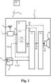
- Fig. 1 is a block diagram of an exemplary hearing device 2 according to the disclosure.
- the hearing device 2 comprises an antenna 4 for converting a first wireless input signal 5 from an external device 30 to an antenna output signal.
- the hearing device 2 comprises a radio transceiver 7 coupled to the antenna 4 for converting the antenna output signal to a transceiver input signal 10.
- the transceiver input signal 10 may be seen as a streamed speech sound signal from a spouse microphone device.
- the hearing device 2 comprises an input module 6 comprising a first microphone 8.
- the input module 6 may comprise a set of microphones.
- the set of microphones comprises a first microphone 8 for provision of a first input signal 9 and/or a second microphone for provision of a second input signal.
- the first input signal 9 may be seen as an acoustic sound signal.
- the hearing device 2 comprises a processor 16 for processing input signals.
- the processor 16 provides a processor output signal 17 based on the input signals to the processor 16.
- the processor 16 is configured to compensate for a hearing loss of a user and to provide a processor output signal 17 based on input signals.
- the hearing device comprises a receiver 18 for converting the processor output signal 17 to an audio output signal.
- the receiver 18 converts the processor output signal 17 to an audio output signal to be directed towards an eardrum of the hearing device user.
- the hearing device comprises a pre-processor 14.
- the pre-processor 14 is operatively connected to the input module 6 and to the radio transceiver 7.
- the pre-processor 14 is configured to provide a pre-processor output signal 15 based on the first input signal 9 and the transceiver input signal 10.
- the hearing device comprises a controller 12.
- the controller 12 is operatively connected to radio transceiver 7.
- the controller 12 may be operatively connected to the input unit 6, to the pre-processor 14, and/or to the processor 16.
- the controller 12 is configured to estimate the speech intelligibility indicator indicative of speech intelligibility based on the transceiver input signal 10 and a first controller input signal 20.
- the first controller input signal 20 may be the first input signal 9.
- the first controller input signal 20 may be the pre-processor output signal 15.
- the first controller input signal 20 is the processor output signal 17.
- the controller 12 comprises a speech intelligibility estimator 12a for estimating a speech intelligibility indicator indicative of speech intelligibility based on the transceiver input signal 10.
- the controller 12 is configured to provide a controller output signal 13 based on the speech intelligibility indicator estimated by the speech intelligibility estimator 12a.
- the controller 12 is configured to control the pre-processor 14 based on the controller output signal 13.
- the speech intelligibility estimator 12a is configured to estimate the speech intelligibility indicator by comparing the transceiver input signal 10 and the first controller input signal 20.
- the speech intelligibility estimator 12a may comprises a comparator module 12ab.
- the transceiver input signal 10 serves as the clean reference signal (as it originates from the first wireless input signal) while the first controller input signal 20 may serve as the noisy speech signal.
- the speech intelligibility estimator 12a is configured to compare the transceiver input signal 10 and the first controller input signal 20 based on a modulation of the transceiver input signal 10 and a modulation of the first controller input signal 20.
- the speech intelligibility estimator 12a may be configured to compare the transceiver input signal 10 and the first controller input signal 20 based on a correlation between one or more spectral and/or temporal representations of the transceiver input signal 10 and one or more spectral and/or temporal representations of the first controller input signal 20.
- the speech intelligibility estimator 12a may be configured to estimate the speech intelligibility indicator using a short-time objective intelligibility estimator 12ac.
- the short-time objective intelligibility estimator 12ac is configured to compare the transceiver input signal 10 and the first controller input signal 20 in one or more short time segments, such as by deriving a correlation coefficient between temporal envelops of the transceiver input signal 10 and the first controller input signal 20 in short-time overlapping segments.
- the controller 12 is configured to determine the pre-processing scheme based on the speech intelligibility indicator. According to the invention, the controller is configured to determine the pre-processing scheme based on the speech intelligibility indicator by determining one or more first gain parameters of the pre-processing scheme and one or more second gain parameter of the pre-processing scheme. It may be envisaged that the controller output signal 13 reflects the pre-processing scheme, such as parameters of the pre-processing scheme. For example, the controller output signal 13 may comprise the one or more first gain parameters and/or the one or more second gain parameters.
- the pre-processor 14 is configured to apply, based on the controller output signal 13, a pre-processing scheme to the first input signal 9 and the transceiver input signal 10.
- the pre-processor 14 is configured to apply the one or more first gain parameters to the first input signal 9 and the one or more second gain parameters to the transceiver input signal 10.
- the one or more first gain parameters may comprise a broadband first gain and the one or more second gain parameters comprise a broadband second gain.
- the one or more first gain parameters may comprise a first set of filter coefficients and the one or more second gain parameters may comprise a second set of filter coefficients.
- the controller output signal 13 may comprise a broadband first gain and/or a broadband second gain.
- the controller output signal 13 may comprise a first set of filter coefficients and/or a second set of filter coefficients.
- the controller 12 is configured to determine the one or more first gain parameters and the one or more second gain parameters by measuring a speech intelligibility indicator in each frequency band, and generating one or more first frequency dependent gain parameters and one or more second frequency dependent gain parameters based on the speech intelligibility indicator measured in each frequency band.
- the set of microphones comprises a second microphone for provision of a second input signal.
- Fig. 2 is a block diagram of an exemplary hearing device 2A, which is not according to the invention, wherein the first controller input signal 20 is a first input signal 9, 20.
- the hearing device 2A comprises a controller 12.
- the controller 12 is operatively connected to radio transceiver 7 and to the input unit 6.
- the controller 12 is configured to estimate the speech intelligibility indicator indicative of speech intelligibility based on the transceiver input signal 10 (e.g. a streamed sound signal from the external device) and a first input signal 9, 20 (e.g. an acoustic signal from the microphone).
- the controller 12 comprises a speech intelligibility estimator 12a for estimating a speech intelligibility indicator based on the transceiver input signal 10 and the first input signal 9, 20.
- the speech intelligibility estimator 12a is configured to estimate the speech intelligibility indicator by comparing the transceiver input signal 10 and the first input signal 9, 20.
- the transceiver input signal 10 serves as the clean reference signal (as it originates from the first wireless input signal) while the first input signal 9, 20 serves as the noisy speech signal.
- the speech intelligibility estimator 12a may be configured to compare the transceiver input signal 10 and the first input signal 9, 20 based on a modulation of the transceiver input signal 10 and a modulation of the first input signal 9, 20.
- the speech intelligibility estimator 12a may be configured to compare the transceiver input signal 10 and the first input signal 9, 20 based on a correlation between one or more spectral and/or temporal representations of the transceiver input signal 10 and one or more spectral and/or temporal representations of the first input signal 9, 20.
- the speech intelligibility estimator 12a may be configured to estimate the speech intelligibility indicator using a short-time objective intelligibility estimator 12ac.
- the short-time objective intelligibility estimator 12ac is configured to compare the transceiver input signal 10 and the first input signal 9, 20 in one or more short time segments, such as by deriving a correlation coefficient between temporal envelops of the transceiver input signal 10 and of the first input signal 9, 20 in short-time overlapping segments.
- the controller 12 is configured to provide a controller output signal 13 based on the speech intelligibility indicator estimated by the speech intelligibility estimator 12a.
- the pre-processor 14 is configured to apply, based on the controller output signal 13, a pre-processing scheme to the first input signal 9 and the transceiver input signal 10.
- Fig. 3 is a block diagram of an exemplary hearing device 2B, which is not according to the invention, wherein the first controller input signal 20 is a pre-processor output signal 15, 20.
- the hearing device 2B comprises a controller 12.
- the controller 12 is operatively connected to radio transceiver 7 and to the pre-processor 14.
- the controller 12 is configured to estimate the speech intelligibility indicator indicative of speech intelligibility based on the transceiver input signal 10 and a pre-processor output signal 15, 20.
- the controller 12 comprises a speech intelligibility estimator 12a for estimating a speech intelligibility indicator based on the transceiver input signal 10 and the pre-processor output signal 15, 20.
- the speech intelligibility estimator 12a is configured to estimate the speech intelligibility indicator by comparing the transceiver input signal 10 and the pre-processor output signal 15, 20.
- the transceiver input signal 10 serves as the clean reference signal (as it originates from the first wireless input signal) while the pre-processor output signal 15, 20 serves as the noisy speech signal.
- the speech intelligibility indicator is estimated based on the transceiver signal (e.g. the streamed sound signal from the external device) and the mixed signal outputted by the pre-processor (i.e.
- the speech intelligibility estimator 12a may be configured to compare the transceiver input signal 10 and the pre-processor output signal 15, 20 based on a modulation of the transceiver input signal 10 and a modulation of the pre-processor output signal 15, 20.
- the speech intelligibility estimator 12a may be configured to compare the transceiver input signal 10 and the pre-processor output signal 15, 20 based on a correlation between one or more spectral and/or temporal representations of the transceiver input signal 10 and one or more spectral and/or temporal representations of the pre-processor output signal 15, 20.
- the speech intelligibility estimator 12a may be configured to estimate the speech intelligibility indicator using a short-time objective intelligibility estimator 12ac.
- the short-time objective intelligibility estimator 12ac is configured to compare the transceiver input signal 10 and the pre-processor output signal 15, 20 in one or more short time segments, such as by deriving a correlation coefficient between temporal envelops of the transceiver input signal 10 and of the pre-processor output signal 15, 20 in short-time overlapping segments.
- the controller 12 is configured to provide a controller output signal 13 based on the speech intelligibility indicator estimated by the speech intelligibility estimator.
- the pre-processor 14 is configured to apply, based on the controller output signal 13, a pre-processing scheme to the first input signal 9 and the transceiver input signal 10. Estimating the speech intelligibility based the transceiver input signal 10 and the pre-processor output signal 15, 20 results in an increased reliability and precision in estimating the speech intelligibility.
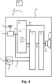
- Fig. 4 is a block diagram of an exemplary hearing device 2C according to the disclosure, wherein the first controller input signal 20 is a processor output signal 17, 20.
- the hearing device 2C comprises a controller 12.
- the controller 12 is operatively connected to radio transceiver 7 and to the pre-processor 14.
- the controller 12 is configured to estimate the speech intelligibility indicator indicative of speech intelligibility based on the transceiver input signal 10 and a processor output signal 17, 20.
- the controller 12 comprises a speech intelligibility estimator 12a for estimating a speech intelligibility indicator based on the transceiver input signal 10 and the processor output signal 17, 20.
- the speech intelligibility estimator 12a is configured to estimate the speech intelligibility indicator by comparing the transceiver input signal 10 and the processor output signal 17, 20.
- the transceiver input signal 10 serves as the clean reference signal (as it originates from the first wireless input signal) while the processor output signal 17, 20 serves as the noisy speech signal.
- the speech intelligibility estimator 12a is configured to compare the transceiver input signal 10 and the processor output signal 17, 20 based on a modulation of the transceiver input signal 10 and a modulation of the processor output signal 17, 20.
- the speech intelligibility estimator 12a may be configured to compare the transceiver input signal 10 and the processor output signal 17, 20 based on a correlation between one or more spectral and/or temporal representations of the transceiver input signal 10 and one or more spectral and/or temporal representations of the processor output signal 17, 20.
- the speech intelligibility estimator 12a may be configured to estimate the speech intelligibility indicator using a short-time objective intelligibility estimator 12ac.
- the short-time objective intelligibility estimator 12ac is configured to compare the transceiver input signal 10 and the processor output signal 17, 20 in one or more short time segments, such as by deriving a correlation coefficient between temporal envelops of the transceiver input signal 10 and of the processor output signal 17, 20 in short-time overlapping segments.
- the controller 12 is configured to provide a controller output signal 13 based on the speech intelligibility indicator estimated by the speech intelligibility estimator.
- the pre-processor 14 is configured to apply, based on the controller output signal 13, a pre-processing scheme to the first input signal 9 and the transceiver input signal 10.
- Fig. 5 is a block diagram illustrating an exemplary pre-processor 14' according to the disclosure, wherein the pre-processor 14' comprises a first gain control module 14a and a second gain control module 14b.
- the pre-processor 14' is configured to pre-process at least one of the first input signal 9 and the transceiver input signal 10.
- the pre-processor 14' is configured to receive a controller output signal 13 comprising one or more first gain parameters and one or more second gain parameters.
- the pre-processor 14's is configured to apply, based on the controller output signal 13, a pre-processing scheme to the first input signal 9 and the transceiver input signal 10. In other words, the pre-processor 14' controls the gain of the first input signal 9 and of the transceiver input signal 10 based on the controller output signal 13.
- the controller output signal 13 comprises a first broadband gain ⁇ and a second broadband gain ⁇ .
- the broadband gain ⁇ and the second broadband gain ⁇ are derived in the controller by measuring the speech intelligibility.
- the pre-processor 14' is configured to apply the first gain parameter ⁇ to the first input signal 9 and the second gain parameter ⁇ to the transceiver input signal 10.
- the pre-processor 14' comprises a first gain control module 14a and a second gain control module 14b.
- the pre-processor 14's is configured to apply the first broadband gain ⁇ to the first input signal 9 using the first gain control module 14a.
- the pre-processor 14' comprises a mixer module 14c that is configured to mix the signal provided by the first gain control module 14a and the signal provided by the second gain control module 14b for provision of the pre-processor output signal 15.
- Fig. 6 is a block diagram illustrating an exemplary pre-processor 14" according to the disclosure, wherein the pre-processor 14" comprises a first filter 14d and a second filter 14e.
- the pre-processor 14" is configured to pre-process at least one of the first input signal 9 and the transceiver input signal 10.
- the pre-processor 14' is configured to receive a controller output signal 13 comprising one or more first gain parameters and one or more second gain parameters.
- the pre-processor 14's is configured to apply, based on the controller output signal 13, a pre-processing scheme to the first input signal 9 and the transceiver input signal 10.
- the controller output signal 13 is indicative of the pre-processing scheme.
- the pre-processor 14" comprises a first filter 14d for filtering the first input signal 9 and a second filter 14e for filtering the transceiver input signal 10.
- the first filter 14d and/or the second filter 14e may be adaptive filters.
- the one or more first gain parameters of the controller output signal 13 comprise a first set of filter coefficients.
- the one or more second gain parameters of the controller output signal 13 comprise a second set of filter coefficients.
- the pre-processor 14" is configured to apply a pre-processing scheme by applying the first set of filter coefficients in the first filter 14d.
- the pre-processor 14" is configured to apply a pre-processing scheme by applying the second set of filter coefficients in the second filter 14e.
- the pre-processor 14" comprises a mixer module 14f that is configured to mix the signal provided by the first filter 14d and the signal provided by the second filter 14e for provision of the pre-processor output signal 15.
- An exemplary hearing device comprising the pre-processor 14" is capable of frequency shaping the first input signal and the transceiver input signal to optimize the intelligibility of the mixture of the first input signal and the transceiver input signal. Simply put, this makes it possible to frequency shape the acoustic sound signal captured by the microphone and the streamed sound signal from the external device to optimize the intelligibility of the mixture.
- Fig. 7 is a flow diagram of an exemplary method 100 of operating a hearing device according to the disclosure.
- the method 100 of operating a hearing device may be performed in a hearing device or in a hearing system according to this disclosure.
- the method 100 comprises receiving 102, e.g. at an antenna of the hearing device, a first wireless input signal from an external device and converting, e.g. at a radio transceiver of the hearing device, the first wireless input signal to a transceiver input signal.
- the method 100 comprises receiving 104, e.g. at an input module of the hearing device, an audio signal and converting the audio signal to one or more input signals including a first input signal.
- the method comprises estimating 106 a speech intelligibility indicator indicative of speech intelligibility based on the transceiver input signal and a first controller input signal.
- Estimating 106 a speech intelligibility indicator may be performed at a speech intelligibility estimator of the hearing device and/or at a controller of the hearing device.
- the first controller input signal is the first input signal.
- estimating 106 the speech intelligibility indicator may be performed based on the transceiver input signal and the first input signal.
- the first controller input signal is the pre-processor output signal.
- estimating 106 the speech intelligibility indicator may be performed based on the transceiver input signal and the pre-processor output signal.
- the first controller input signal is the processor output signal.
- estimating 106 the speech intelligibility indicator is performed based on the transceiver input signal and the processor output signal.
- the method comprises providing 108 a controller output signal based on the speech intelligibility indicator, such as providing 108 controller output signal from a controller of the hearing device to a pre-processor of the hearing device.
- the method comprises applying 110, based on the controller output signal, a pre-processing scheme to at least one of the first input signal and the transceiver input signal. Applying 110 the pre-processing scheme to at least one of the first input signal and the transceiver input signal may be performed at a pre-processor of the hearing device. In one or more exemplary methods, applying 110, based on the controller output signal, the pre-processing scheme to at least one of the first input signal and the transceiver input signal comprises applying 110a, based on the controller output signal, the pre-processing scheme to the first input signal and the transceiver input signal.
- estimating 106 the speech intelligibility indicator comprises comparing 106a the transceiver input signal and the first controller input signal, wherein comparing 106a the transceiver input signal and the first controller input signal may be performed based on a modulation 106b of the transceiver input signal and a modulation of the first controller input signal.
- comparing 106a the transceiver input signal and the first controller input signal may comprise determining 106c a correlation between one or more spectral and/or temporal representations of the transceiver input signal and one or more spectral and/or temporal representations of the first controller input signal.
- comparing 106a the transceiver input signal and the first controller input signal is performed using 106d a short-time objective intelligibility estimator, wherein the short-time objective intelligibility estimator is configured to compare the transceiver input signal and the first controller input signal in one or more short time segments.
- comparing 106d the transceiver input signal and the first controller input signal in one or more short time segments may comprise deriving a correlation coefficient between temporal envelops of the transceiver input signal and of the first controller input signal in short-time overlapping segments.
- the method 100 comprises determining 107 the pre-processing scheme based on the speech intelligibility indicator. Determining 107 the pre-processing scheme based on the speech intelligibility indicator may be performed at the controller module of the hearing device. According to the invention, determining 107 the pre-processing scheme based on the speech intelligibility indicator comprises determining 107a one or more first gain parameters of the pre-processing scheme and one or more second gain parameter of the pre-processing scheme. The controller output signal may comprise the one or more first gain parameters of the pre-processing scheme and the one or more second gain parameter of the pre-processing scheme. The controller output signal is indicative of the pre-processing scheme selected. For example, the one or more first gain parameters may comprise a broadband first gain and the one or more second gain parameters may comprise a broadband second gain.
- applying 110, based on the controller output signal, a pre-processing scheme to the first input signal and the transceiver input signal comprises 110b: applying the one or more first gain parameters to the first input signal and applying the one or more second gain parameters to the transceiver input signal.
- applying 110, based on the controller output signal, a pre-processing scheme to the first input signal and the transceiver input signal comprises 110c: filtering the first input signal and filtering the transceiver input signal.
- filtering the first input signal may be performed at a first filter and filtering the transceiver input signal may be performed at a second filter over vice versa.
- the one or more first gain parameters comprise a first set of filter coefficients and the one or more second gain parameters comprise a second set of filter coefficients.
- the controller output signal may comprise the first set of filter coefficients and/or the second set of filter coefficients.
- the hearing devices, and methods discloses herein allow to obtain an estimation of the speech intelligibility indicator and adaptation of the pre-processing applied to the input signals and to the transceiver input signals according to the estimated speech intelligibility indicator.
- This provides the advantage of adapting the processing of the transceiver input signal (e.g. signal from the one or more external/spouse microphone devices) with the input signal from the one or more microphones.
- the present disclosure advantageously enables the hearing device to attenuate the input signals at an optimal level. It is an advantage of this disclosure to prevent the hearing device user to be disconnected from the audio environment while still being able to understand the speech received via the transceiver input signal from the external device.
- first, second, third and fourth does not imply any particular order, but are included to identify individual elements.
- first, second, etc. does not denote any order or importance, but rather the terms first, second, etc. are used to distinguish one element from another.
- first and second are used here and elsewhere for labelling purposes only and are not intended to denote any specific spatial or temporal ordering.
- labelling of a first element does not imply the presence of a second element and vice versa.
Landscapes
- Engineering & Computer Science (AREA)
- Physics & Mathematics (AREA)
- Acoustics & Sound (AREA)
- Signal Processing (AREA)
- Health & Medical Sciences (AREA)
- General Health & Medical Sciences (AREA)
- Neurosurgery (AREA)
- Otolaryngology (AREA)
- Computer Networks & Wireless Communication (AREA)
- Circuit For Audible Band Transducer (AREA)
Priority Applications (5)
| Application Number | Priority Date | Filing Date | Title |
|---|---|---|---|
| EP24209322.7A EP4478745A3 (en) | 2017-05-09 | 2017-05-09 | Speech intelligibility-based hearing devices and associated methods |
| EP17170175.8A EP3402217B1 (en) | 2017-05-09 | 2017-05-09 | Speech intelligibility-based hearing devices and associated methods |
| JP2018089447A JP7023173B2 (ja) | 2017-05-09 | 2018-05-07 | 音声明瞭度に基づく聴覚機器とそれに関連した方法 |
| US15/974,028 US10993048B2 (en) | 2017-05-09 | 2018-05-08 | Speech intelligibility-based hearing devices and associated methods |
| CN201810437256.7A CN108882110B (zh) | 2017-05-09 | 2018-05-09 | 基于语音清晰度的听力设备及相关方法 |
Applications Claiming Priority (1)
| Application Number | Priority Date | Filing Date | Title |
|---|---|---|---|
| EP17170175.8A EP3402217B1 (en) | 2017-05-09 | 2017-05-09 | Speech intelligibility-based hearing devices and associated methods |
Related Child Applications (2)
| Application Number | Title | Priority Date | Filing Date |
|---|---|---|---|
| EP24209322.7A Division EP4478745A3 (en) | 2017-05-09 | 2017-05-09 | Speech intelligibility-based hearing devices and associated methods |
| EP24209322.7A Division-Into EP4478745A3 (en) | 2017-05-09 | 2017-05-09 | Speech intelligibility-based hearing devices and associated methods |
Publications (3)
| Publication Number | Publication Date |
|---|---|
| EP3402217A1 EP3402217A1 (en) | 2018-11-14 |
| EP3402217C0 EP3402217C0 (en) | 2025-01-08 |
| EP3402217B1 true EP3402217B1 (en) | 2025-01-08 |
Family
ID=58699011
Family Applications (2)
| Application Number | Title | Priority Date | Filing Date |
|---|---|---|---|
| EP17170175.8A Active EP3402217B1 (en) | 2017-05-09 | 2017-05-09 | Speech intelligibility-based hearing devices and associated methods |
| EP24209322.7A Pending EP4478745A3 (en) | 2017-05-09 | 2017-05-09 | Speech intelligibility-based hearing devices and associated methods |
Family Applications After (1)
| Application Number | Title | Priority Date | Filing Date |
|---|---|---|---|
| EP24209322.7A Pending EP4478745A3 (en) | 2017-05-09 | 2017-05-09 | Speech intelligibility-based hearing devices and associated methods |
Country Status (4)
| Country | Link |
|---|---|
| US (1) | US10993048B2 (https=) |
| EP (2) | EP3402217B1 (https=) |
| JP (1) | JP7023173B2 (https=) |
| CN (1) | CN108882110B (https=) |
Families Citing this family (5)
| Publication number | Priority date | Publication date | Assignee | Title |
|---|---|---|---|---|
| EP3576088A1 (en) * | 2018-05-30 | 2019-12-04 | Fraunhofer Gesellschaft zur Förderung der Angewand | Audio similarity evaluator, audio encoder, methods and computer program |
| GB201819422D0 (en) | 2018-11-29 | 2019-01-16 | Sonova Ag | Methods and systems for hearing device signal enhancement using a remote microphone |
| CN113823302A (zh) * | 2020-06-19 | 2021-12-21 | 北京新能源汽车股份有限公司 | 一种语言清晰度的优化方法及装置 |
| EP4106349A1 (en) * | 2021-06-15 | 2022-12-21 | Oticon A/s | A hearing device comprising a speech intelligibility estimator |
| US20240242704A1 (en) * | 2023-01-17 | 2024-07-18 | Sonova Ag | Systems and Methods for Optimizing Voice Notifications Provided by Way of a Hearing Device |
Family Cites Families (17)
| Publication number | Priority date | Publication date | Assignee | Title |
|---|---|---|---|---|
| US6694034B2 (en) * | 2000-01-07 | 2004-02-17 | Etymotic Research, Inc. | Transmission detection and switch system for hearing improvement applications |
| US6944474B2 (en) * | 2001-09-20 | 2005-09-13 | Sound Id | Sound enhancement for mobile phones and other products producing personalized audio for users |
| EP1609134A1 (en) * | 2003-01-31 | 2005-12-28 | Oticon A/S | Sound system improving speech intelligibility |
| EP1754307A4 (en) * | 2004-03-05 | 2010-02-17 | Etymotic Res Inc | COMPANION MICROPHONE SYSTEM AND METHOD |
| DE102008052176B4 (de) * | 2008-10-17 | 2013-11-14 | Siemens Medical Instruments Pte. Ltd. | Verfahren und Hörgerät zur Parameteradaption durch Ermittlung einer Sprachverständlichkeitsschwelle |
| US8433568B2 (en) * | 2009-03-29 | 2013-04-30 | Cochlear Limited | Systems and methods for measuring speech intelligibility |
| EP2372700A1 (en) * | 2010-03-11 | 2011-10-05 | Oticon A/S | A speech intelligibility predictor and applications thereof |
| US9167359B2 (en) * | 2010-07-23 | 2015-10-20 | Sonova Ag | Hearing system and method for operating a hearing system |
| JP5626366B2 (ja) | 2011-01-04 | 2014-11-19 | 富士通株式会社 | 音声制御装置、音声制御方法及び音声制御プログラム |
| EP2936834A1 (en) * | 2012-12-20 | 2015-10-28 | Widex A/S | Hearing aid and a method for improving speech intelligibility of an audio signal |
| WO2014198332A1 (en) * | 2013-06-14 | 2014-12-18 | Widex A/S | Method of signal processing in a hearing aid system and a hearing aid system |
| US9031838B1 (en) * | 2013-07-15 | 2015-05-12 | Vail Systems, Inc. | Method and apparatus for voice clarity and speech intelligibility detection and correction |
| EP2840807A1 (en) | 2013-08-19 | 2015-02-25 | Oticon A/s | External microphone array and hearing aid using it |
| CN103813252B (zh) | 2014-03-03 | 2017-05-31 | 深圳市微纳集成电路与系统应用研究院 | 用于助听器的放大倍数确定方法及系统 |
| US9875754B2 (en) * | 2014-05-08 | 2018-01-23 | Starkey Laboratories, Inc. | Method and apparatus for pre-processing speech to maintain speech intelligibility |
| EP3057335B1 (en) * | 2015-02-11 | 2017-10-11 | Oticon A/s | A hearing system comprising a binaural speech intelligibility predictor |
| DK3214620T3 (da) * | 2016-03-01 | 2019-11-25 | Oticon As | Monaural forstyrrende taleforståelighedsforudsigelsesenhed, et høreapparat og et binauralt høreapparatsystem |
-
2017
- 2017-05-09 EP EP17170175.8A patent/EP3402217B1/en active Active
- 2017-05-09 EP EP24209322.7A patent/EP4478745A3/en active Pending
-
2018
- 2018-05-07 JP JP2018089447A patent/JP7023173B2/ja active Active
- 2018-05-08 US US15/974,028 patent/US10993048B2/en active Active
- 2018-05-09 CN CN201810437256.7A patent/CN108882110B/zh active Active
Also Published As
| Publication number | Publication date |
|---|---|
| US10993048B2 (en) | 2021-04-27 |
| US20190132688A1 (en) | 2019-05-02 |
| EP4478745A3 (en) | 2025-03-12 |
| EP3402217C0 (en) | 2025-01-08 |
| CN108882110B (zh) | 2022-03-18 |
| JP7023173B2 (ja) | 2022-02-21 |
| EP4478745A2 (en) | 2024-12-18 |
| EP3402217A1 (en) | 2018-11-14 |
| JP2018207480A (ja) | 2018-12-27 |
| CN108882110A (zh) | 2018-11-23 |
Similar Documents
| Publication | Publication Date | Title |
|---|---|---|
| US11553287B2 (en) | Hearing device with neural network-based microphone signal processing | |
| EP3122072B1 (en) | Audio processing device, system, use and method | |
| US8204263B2 (en) | Method of estimating weighting function of audio signals in a hearing aid | |
| EP3402217B1 (en) | Speech intelligibility-based hearing devices and associated methods | |
| CN106878905B (zh) | 确定含噪语音信号的客观感知量的方法 | |
| US10536785B2 (en) | Hearing device and method with intelligent steering | |
| US11653153B2 (en) | Binaural hearing system comprising bilateral compression | |
| US10966032B2 (en) | Hearing apparatus with a facility for reducing a microphone noise and method for reducing microphone noise | |
| US20140064496A1 (en) | Binaural enhancement of tone language for hearing assistance devices | |
| CN103546849B (zh) | 具有频率无掩蔽的双耳助听器 | |
| US10511917B2 (en) | Adaptive level estimator, a hearing device, a method and a binaural hearing system | |
| EP3837861B1 (en) | Method of operating a hearing aid system and a hearing aid system | |
| US12212927B2 (en) | Method for operating a hearing device, and hearing device | |
| US20190174236A1 (en) | Hearing device and method with flexible control of beamforming |
Legal Events
| Date | Code | Title | Description |
|---|---|---|---|
| PUAI | Public reference made under article 153(3) epc to a published international application that has entered the european phase |
Free format text: ORIGINAL CODE: 0009012 |
|
| STAA | Information on the status of an ep patent application or granted ep patent |
Free format text: STATUS: THE APPLICATION HAS BEEN PUBLISHED |
|
| AK | Designated contracting states |
Kind code of ref document: A1 Designated state(s): AL AT BE BG CH CY CZ DE DK EE ES FI FR GB GR HR HU IE IS IT LI LT LU LV MC MK MT NL NO PL PT RO RS SE SI SK SM TR |
|
| AX | Request for extension of the european patent |
Extension state: BA ME |
|
| STAA | Information on the status of an ep patent application or granted ep patent |
Free format text: STATUS: REQUEST FOR EXAMINATION WAS MADE |
|
| 17P | Request for examination filed |
Effective date: 20190514 |
|
| RBV | Designated contracting states (corrected) |
Designated state(s): AL AT BE BG CH CY CZ DE DK EE ES FI FR GB GR HR HU IE IS IT LI LT LU LV MC MK MT NL NO PL PT RO RS SE SI SK SM TR |
|
| STAA | Information on the status of an ep patent application or granted ep patent |
Free format text: STATUS: EXAMINATION IS IN PROGRESS |
|
| 17Q | First examination report despatched |
Effective date: 20190626 |
|
| GRAP | Despatch of communication of intention to grant a patent |
Free format text: ORIGINAL CODE: EPIDOSNIGR1 |
|
| STAA | Information on the status of an ep patent application or granted ep patent |
Free format text: STATUS: GRANT OF PATENT IS INTENDED |
|
| INTG | Intention to grant announced |
Effective date: 20240424 |
|
| GRAL | Information related to payment of fee for publishing/printing deleted |
Free format text: ORIGINAL CODE: EPIDOSDIGR3 |
|
| GRAS | Grant fee paid |
Free format text: ORIGINAL CODE: EPIDOSNIGR3 |
|
| GRAA | (expected) grant |
Free format text: ORIGINAL CODE: 0009210 |
|
| STAA | Information on the status of an ep patent application or granted ep patent |
Free format text: STATUS: THE PATENT HAS BEEN GRANTED |
|
| AK | Designated contracting states |
Kind code of ref document: B1 Designated state(s): AL AT BE BG CH CY CZ DE DK EE ES FI FR GB GR HR HU IE IS IT LI LT LU LV MC MK MT NL NO PL PT RO RS SE SI SK SM TR |
|
| REG | Reference to a national code |
Ref country code: GB Ref legal event code: FG4D |
|
| REG | Reference to a national code |
Ref country code: CH Ref legal event code: EP |
|
| REG | Reference to a national code |
Ref country code: DE Ref legal event code: R096 Ref document number: 602017087209 Country of ref document: DE |
|
| REG | Reference to a national code |
Ref country code: IE Ref legal event code: FG4D |
|
| U01 | Request for unitary effect filed |
Effective date: 20250203 |
|
| U07 | Unitary effect registered |
Designated state(s): AT BE BG DE DK EE FI FR IT LT LU LV MT NL PT RO SE SI Effective date: 20250212 |
|
| U20 | Renewal fee for the european patent with unitary effect paid |
Year of fee payment: 9 Effective date: 20250516 |
|
| PG25 | Lapsed in a contracting state [announced via postgrant information from national office to epo] |
Ref country code: RS Free format text: LAPSE BECAUSE OF FAILURE TO SUBMIT A TRANSLATION OF THE DESCRIPTION OR TO PAY THE FEE WITHIN THE PRESCRIBED TIME-LIMIT Effective date: 20250408 |
|
| PG25 | Lapsed in a contracting state [announced via postgrant information from national office to epo] |
Ref country code: PL Free format text: LAPSE BECAUSE OF FAILURE TO SUBMIT A TRANSLATION OF THE DESCRIPTION OR TO PAY THE FEE WITHIN THE PRESCRIBED TIME-LIMIT Effective date: 20250108 |
|
| PG25 | Lapsed in a contracting state [announced via postgrant information from national office to epo] |
Ref country code: ES Free format text: LAPSE BECAUSE OF FAILURE TO SUBMIT A TRANSLATION OF THE DESCRIPTION OR TO PAY THE FEE WITHIN THE PRESCRIBED TIME-LIMIT Effective date: 20250108 |
|
| PG25 | Lapsed in a contracting state [announced via postgrant information from national office to epo] |
Ref country code: NO Free format text: LAPSE BECAUSE OF FAILURE TO SUBMIT A TRANSLATION OF THE DESCRIPTION OR TO PAY THE FEE WITHIN THE PRESCRIBED TIME-LIMIT Effective date: 20250408 Ref country code: IS Free format text: LAPSE BECAUSE OF FAILURE TO SUBMIT A TRANSLATION OF THE DESCRIPTION OR TO PAY THE FEE WITHIN THE PRESCRIBED TIME-LIMIT Effective date: 20250508 |
|
| PG25 | Lapsed in a contracting state [announced via postgrant information from national office to epo] |
Ref country code: HR Free format text: LAPSE BECAUSE OF FAILURE TO SUBMIT A TRANSLATION OF THE DESCRIPTION OR TO PAY THE FEE WITHIN THE PRESCRIBED TIME-LIMIT Effective date: 20250108 |
|
| PG25 | Lapsed in a contracting state [announced via postgrant information from national office to epo] |
Ref country code: GR Free format text: LAPSE BECAUSE OF FAILURE TO SUBMIT A TRANSLATION OF THE DESCRIPTION OR TO PAY THE FEE WITHIN THE PRESCRIBED TIME-LIMIT Effective date: 20250409 |
|
| PGFP | Annual fee paid to national office [announced via postgrant information from national office to epo] |
Ref country code: CH Payment date: 20250601 Year of fee payment: 9 |
|
| PG25 | Lapsed in a contracting state [announced via postgrant information from national office to epo] |
Ref country code: SM Free format text: LAPSE BECAUSE OF FAILURE TO SUBMIT A TRANSLATION OF THE DESCRIPTION OR TO PAY THE FEE WITHIN THE PRESCRIBED TIME-LIMIT Effective date: 20250108 |
|
| PG25 | Lapsed in a contracting state [announced via postgrant information from national office to epo] |
Ref country code: CZ Free format text: LAPSE BECAUSE OF FAILURE TO SUBMIT A TRANSLATION OF THE DESCRIPTION OR TO PAY THE FEE WITHIN THE PRESCRIBED TIME-LIMIT Effective date: 20250108 |
|
| PG25 | Lapsed in a contracting state [announced via postgrant information from national office to epo] |
Ref country code: SK Free format text: LAPSE BECAUSE OF FAILURE TO SUBMIT A TRANSLATION OF THE DESCRIPTION OR TO PAY THE FEE WITHIN THE PRESCRIBED TIME-LIMIT Effective date: 20250108 |
|
| PLBE | No opposition filed within time limit |
Free format text: ORIGINAL CODE: 0009261 |
|
| STAA | Information on the status of an ep patent application or granted ep patent |
Free format text: STATUS: NO OPPOSITION FILED WITHIN TIME LIMIT |
|
| 26N | No opposition filed |
Effective date: 20251009 |
|
| PG25 | Lapsed in a contracting state [announced via postgrant information from national office to epo] |
Ref country code: MC Free format text: LAPSE BECAUSE OF FAILURE TO SUBMIT A TRANSLATION OF THE DESCRIPTION OR TO PAY THE FEE WITHIN THE PRESCRIBED TIME-LIMIT Effective date: 20250108 |
|
| PGFP | Annual fee paid to national office [announced via postgrant information from national office to epo] |
Ref country code: GB Payment date: 20260317 Year of fee payment: 10 |
|
| PG25 | Lapsed in a contracting state [announced via postgrant information from national office to epo] |
Ref country code: IE Free format text: LAPSE BECAUSE OF NON-PAYMENT OF DUE FEES Effective date: 20250509 |