EP3402019A1 - Arc flash resistant enclosure with segregated cooling - Google Patents
Arc flash resistant enclosure with segregated cooling Download PDFInfo
- Publication number
- EP3402019A1 EP3402019A1 EP18171181.3A EP18171181A EP3402019A1 EP 3402019 A1 EP3402019 A1 EP 3402019A1 EP 18171181 A EP18171181 A EP 18171181A EP 3402019 A1 EP3402019 A1 EP 3402019A1
- Authority
- EP
- European Patent Office
- Prior art keywords
- compartment
- enclosure
- blower
- arc flash
- intake vent
- Prior art date
- Legal status (The legal status is an assumption and is not a legal conclusion. Google has not performed a legal analysis and makes no representation as to the accuracy of the status listed.)
- Granted
Links
Images


Classifications
-
- H—ELECTRICITY
- H01—ELECTRIC ELEMENTS
- H01H—ELECTRIC SWITCHES; RELAYS; SELECTORS; EMERGENCY PROTECTIVE DEVICES
- H01H33/00—High-tension or heavy-current switches with arc-extinguishing or arc-preventing means
- H01H33/02—Details
- H01H33/04—Means for extinguishing or preventing arc between current-carrying parts
- H01H33/08—Stationary parts for restricting or subdividing the arc, e.g. barrier plate
-
- H—ELECTRICITY
- H05—ELECTRIC TECHNIQUES NOT OTHERWISE PROVIDED FOR
- H05K—PRINTED CIRCUITS; CASINGS OR CONSTRUCTIONAL DETAILS OF ELECTRIC APPARATUS; MANUFACTURE OF ASSEMBLAGES OF ELECTRICAL COMPONENTS
- H05K7/00—Constructional details common to different types of electric apparatus
- H05K7/20—Modifications to facilitate cooling, ventilating, or heating
- H05K7/20536—Modifications to facilitate cooling, ventilating, or heating for racks or cabinets of standardised dimensions, e.g. electronic racks for aircraft or telecommunication equipment
- H05K7/20554—Forced ventilation of a gaseous coolant
-
- H—ELECTRICITY
- H02—GENERATION; CONVERSION OR DISTRIBUTION OF ELECTRIC POWER
- H02B—BOARDS, SUBSTATIONS OR SWITCHING ARRANGEMENTS FOR THE SUPPLY OR DISTRIBUTION OF ELECTRIC POWER
- H02B1/00—Frameworks, boards, panels, desks, casings; Details of substations or switching arrangements
- H02B1/56—Cooling; Ventilation
- H02B1/565—Cooling; Ventilation for cabinets
-
- H—ELECTRICITY
- H02—GENERATION; CONVERSION OR DISTRIBUTION OF ELECTRIC POWER
- H02B—BOARDS, SUBSTATIONS OR SWITCHING ARRANGEMENTS FOR THE SUPPLY OR DISTRIBUTION OF ELECTRIC POWER
- H02B13/00—Arrangement of switchgear in which switches are enclosed in, or structurally associated with, a casing, e.g. cubicle
- H02B13/02—Arrangement of switchgear in which switches are enclosed in, or structurally associated with, a casing, e.g. cubicle with metal casing
- H02B13/025—Safety arrangements, e.g. in case of excessive pressure or fire due to electrical defect
-
- H—ELECTRICITY
- H02—GENERATION; CONVERSION OR DISTRIBUTION OF ELECTRIC POWER
- H02H—EMERGENCY PROTECTIVE CIRCUIT ARRANGEMENTS
- H02H3/00—Emergency protective circuit arrangements for automatic disconnection directly responsive to an undesired change from normal electric working condition with or without subsequent reconnection ; integrated protection
- H02H3/16—Emergency protective circuit arrangements for automatic disconnection directly responsive to an undesired change from normal electric working condition with or without subsequent reconnection ; integrated protection responsive to fault current to earth, frame or mass
-
- H—ELECTRICITY
- H05—ELECTRIC TECHNIQUES NOT OTHERWISE PROVIDED FOR
- H05K—PRINTED CIRCUITS; CASINGS OR CONSTRUCTIONAL DETAILS OF ELECTRIC APPARATUS; MANUFACTURE OF ASSEMBLAGES OF ELECTRICAL COMPONENTS
- H05K7/00—Constructional details common to different types of electric apparatus
- H05K7/20—Modifications to facilitate cooling, ventilating, or heating
- H05K7/20009—Modifications to facilitate cooling, ventilating, or heating using a gaseous coolant in electronic enclosures
- H05K7/20136—Forced ventilation, e.g. by fans
- H05K7/20145—Means for directing air flow, e.g. ducts, deflectors, plenum or guides
Definitions
- Electrical enclosures and cabinets can be used in a wide range of industrial and automation applications.
- electrical enclosures typically include a shell or box made of a heavy gauge sheet metal.
- the enclosures are configured to support electrical circuitry and electrical components therein, and to receive and send electrical power and data signals.
- the enclosures may include both small and large individual units, such as for housing components, such as contactors and other switches.
- larger enclosures can be employed to house various power electronics equipment, control circuits, motor drives, and so forth. For example, in industry it is common to find large enclosures divided into bays or segments for single and three-phase switches, motor controllers, programmable logic controllers, data and power network interfaces, and so forth.
- One challenge in the design and operation of electrical components in enclosures relates to designing the enclosures to withstand the mechanical and thermal effects of an internal arcing fault (also called an arc, arc fault, arc flash, arcing flash, etc.).
- an internal arcing fault also called an arc, arc fault, arc flash, arcing flash, etc.
- certain types of electrical faults can produce arcs that can heat and even vaporize neighboring components and cause sudden pressure increases and localized overheating.
- development of protective circuitry has focused on interrupting such faults extremely quickly, even a few cycles of alternating current can suffice to vaporize wires, insulation, and even component housings.
- Such faults can result in volumes of hot gas that expand and must be channeled and/or vented within or from the enclosure. Further, the faults can produce high temperatures and pressure increases that cause mechanical and thermal stresses on the electrical enclosures.
- Arcing faults can cause damage to equipment and facilities and increase costs due to lost production. They can also present a hazard to personnel in the vicinity due to the location of operator controls on the front door of some enclosures. Accordingly, industrial standards and guides have been developed as a way for manufacturers to demonstrate that the electrical enclosures can withstand the mechanical and thermal effects of an internal arcing fault.
- Air cooled enclosures generally have one or more filtered or unfiltered intake vents and one or more exhaust vents configured as part of a flow path for ambient air to be drawn into the enclosure.
- the ambient air drawn into the enclosure absorbs heat from the internal components and is then exhausted back to the ambient environment.
- the intake and exhaust vents while necessary for air cooling, present challenges with respect to the potential for arc plasma to escape therefrom in the event of an arc fault.
- Disclosed examples include enclosures with segregated or divided cooling paths and improved arc flash resistance.
- a TYPE 12, 50C RATED ambient common bus power conversion enclosure design provides enhanced arc flash protection and segregated cooling for high reliability of imbedded electronics with a degree of protection against circulating dust, falling dirt and dripping noncorrosive liquids.
- Example enclosures and systems can be used in association with AC/DC converters for electroplating or painting systems with modular anode control (MAC) systems to implement an anodic DC electroplating for workpieces and other end use applications.
- MAC modular anode control
- Other example enclosures and systems find wide use in a variety of applications.
- an enclosure comprises a first compartment to operate at a first controlled temperature range, the first compartment including a variable frequency drive, a second compartment to operate at a second controlled temperature range higher than the first controlled temperature range, the second compartment including magnetics and higher temperature rated components, a first intake vent to receive ambient air into the first compartment, a second intake vent to receive ambient air into the second compartment, and a blower to direct air from both the first and second compartments out of the enclosure.
- the ambient air drawn into the first compartment flows along a first cooling path extending from the first intake vent to the blower
- the ambient air drawn into the second compartment flows along a second cooling path extending from the second intake vent to the blower
- a terminal portion of the first flow path joins the second flow path prior to the blower.
- the enclosure can further include a partition at least partially separating the first compartment from the second compartment, and at least one opening in the partition through which the first flow path extends from the first compartment into the second compartment.
- the at least one opening can be at an upper portion of the partition adjacent a top panel of the enclosure.
- At least one door can be provided for accessing the first compartment.
- the at least one door can include the first intake vent, wherein the first intake vent is the only pathway to the ambient environment through the door.
- the blower can be a TYPE 12, 50 degree C enclosure with 2-speed control, or any other suitable blower (e.g., continuously variable speed).
- a first arc flash path of the first compartment can extend between the first intake vent and the blower (exhaust outlet), the arc flash path making at least two 90 degree turns prior to the blower.
- a second arc flash path of the second compartment can extend between the second intake vent and the blower (exhaust outlet), the first arc flash path and the second arc flash path being coextensive within at least a portion of the second compartment. Both the first arc flash path and the second arc flash path can exit the enclosure through a top side of the enclosure (e.g., via the exhaust outlet of the blower).
- the arc flash paths of the present exemplary disclosure dissipate arc energy by increasing the length the arc must travel before exiting the enclosure, and forcing the arc to undergo at least two directional changes prior to exiting the enclosure. Accordingly, in some instances an arc emanating from a lower portion of either of the compartments may be diminished by 75% or more prior to exiting the enclosure.
- an enclosure for electrical equipment comprises a low temperature compartment to operate at a first controlled temperature range, the low temperature compartment configured to house a first set of associated electrical components, a high temperature compartment to operate at a second controlled temperature range higher than the first controlled temperature range, the high temperature compartment configured to house a second set of associated electrical/electronic components, a first intake vent to receive ambient air into the low temperature compartment, a second intake vent to receive ambient air into the high temperature compartment, and a blower to direct air from both the low temperature compartment and the high temperature compartment out of the enclosure.
- Ambient air entering the low temperature compartment flows along a first cooling path extending from the first intake vent to the blower, ambient air entering the high temperature compartment flows along a second cooling path extending from the second intake vent to the blower, and a terminal portion of the first flow path joins the second flow path prior to the blower.
- the enclosure can further comprise a partition at least partially separating the low temperature compartment from the high temperature compartment within the enclosure, and at least one opening in the partition through which the first flow path extends from the low temperature compartment into the high temperature compartment.
- the at least one opening can be at an upper portion of the partition adjacent a top panel of the enclosure.
- At least one door for accessing the first compartment can be provided.
- the at least one door can include the first intake vent, wherein the first intake vent is the only pathway to the ambient environment through the door.
- the blower can be a TYPE 12, 50 degree C 2-speed blower (or continuously variable speed).
- a first arc flash path of the low temperature compartment can extend between the first intake vent and the blower, the arc flash path making at least two 90 degree turns prior to the blower.
- a second arc flash path of the high temperature compartment can extend between the second intake vent and the blower, the first arc flash path and the second arc flash path being coextensive within at least a portion of the second compartment. Both the first arc flash path and the second arc flash path can exit the enclosure through a top side of the enclosure.
- the exemplary enclosure 10 provides segregated cooling (e.g., low temperature/high temperature) within one enclosure, as well as an arc flash resistant design.
- segregated cooling e.g., low temperature/high temperature
- an arc flash resistant design e.g., an arc flash resistant design.
- certain examples provide a 50 degree C TYPE 12 thermal packaging cooling system that segregates electronics into a cool side air compartment, power components and magnetics along with higher temp rated parts in a hot side air compartment, all within one cabinet enclosure.
- Certain examples also provide components in the enclosure (e.g., VFD, DC caps, etc.) to have no more than 5C rise above ambient in the cool side air compartment.
- the enclosure 10 generally comprises a housing H.
- the housing H defines an internal chamber C, which in the illustrated embodiment is divided by a partition P into two compartments - a low temperature compartment LTC (a first compartment) and a high temperature compartment HTC (e.g., a second compartment). It should be appreciated that the internal chamber C can be divided into additional compartments if desired or necessary.
- the low temperature compartment LTC includes a variable frequency drive VFD, and other components configured to operate within the low temperature compartment LTC.
- the low temperature compartment LTC is configured to have no more than a 5 degree C temperature rise over ambient air during operation of the system.
- the high temperature compartment HTC includes magnetics and associated high power components. In some cases, portions of the same component may reside in both the low temperature compartment LTC and the high temperature compartment HTC (e.g., the VFD as seen in FIG. 2 ).
- Segregating the low temperature compartment LTC from the high temperature compartment HTC is desirable considering the Arrhenius Thermal Degradation Law relationship that component life, in general, decreases 1 ⁇ 2 for every 10 degree C rise in temperature.
- a low temperature compartment with sensitive electronics if limited to a 5C rise, may see a 25% reduction in expected life.
- the same electronics in a high temperature compartment with magnetics and high power dissipating devices may be subjected to a typical 20 degree C rise, considered as an optimal cost effective magnetic design.
- the electronics would suffer a 75% reduction in expected life.
- the enclosure 10 includes a first intake vent V1 (three louvered openings shown in later drawings) to receive ambient air into the low temperature compartment LTC, second intake vents V2 (one vent on front and one vent on rear shown in later drawings) to receive ambient air into the high temperature compartment HTC, and a blower B to direct air from both the low temperature compartment LTC and the high temperature compartment HTC out of the enclosure 10.
- First and second cooling flow paths CP1 and CP2 extend between the vents V1 and V2, respectively, and an exhaust outlet of the blower B. It will be appreciated that any suitable number of intake vents V1 and V2 can be used without departing from the scope of the present disclosure.
- cooling flow path CP1 of the low temperature compartment LTC is in fluid communication with the high temperature cooling flow path CP2 via one or more openings O or passageways extending across the partition P.
- the opening O allows air to exit the low temperature compartment LTC and enter the high temperature compartment at a location adjacent to the blower B, in an upper region of the high temperature compartment HTC.
- the blower B is configured to direct exhaust air from each of the low temperature compartment LTC and the high temperature compartment HTC out the top of the enclosure 10.
- the enclosure 10 directs any arc plasma from the low temperature compartment LTC into the high temperature compartment HTC and/or out of the top of enclosure 10 via the blower 10.
- the low temperature compartment LTC is generally closed to the ambient except via the opening O and blower B.
- the single blower B directs air from both the low temperature compartment and the high temperature compartment LTC and HTC out of the enclosure 10, and provides an improved exit location for potential arc flashes.
- the housing H of the enclosure 10 is generally comprised of a plurality of panels (e.g., side panels SP, top panel TP, bottom panel BP) mounted to an internal frame structure F (side panel SP removed in FIGS. 4 and 5 ).
- the enclosure 10 further includes front and rear doors FD and RD (or panels) for permitting access to the interior compartments.
- the only openings in the front and rear doors FD and RD are the vents V1 and V2 for admitting cooling air into the respective low temperature compartment LTC and high temperature compartment HTC.
- the example enclosure 10 includes a large powerful TYPE 12 hot side blower B to pull air from the low temperature compartment LTC and the high temperature compartment HTC, and reduces costs by eliminating door venting and/or door mounted fans (e.g., the doors do not have an exhaust vent).
- Disclosed examples also facilitate meeting a less than 5 degree C rise for the VFD, electronics, low voltage power supply sensors (e.g., associated feedback voltage and current sensors), etc. inside the low temperature (cool) compartment LTC for high reliability and long life (since every 10C cuts life in half).
- the enclosure 10 of the present exemplary embodiment provides, in addition to the segregated cooling paths, improved arc flash resistance.
- the side panels SP and front and rear doors FD and RD have been removed from the enclosure 10 shown in FIGS. 6 and 7 so that the arc flash paths of both the low temperature compartment LTC and high temperature compartment HTC can be illustrated.
- Arc flash incidents may possibly occur as a result of electrical components failing short across the incoming ac power line, limited only by the power source short circuit current interrupt rating. While circuit protection is opening as fast as possible within a few power line cycles, the arc created and expanding gas reaches extreme high temperatures and pressures and will find immediate available openings to exhaust.
- One objective of the exemplary cabinet design is to provide improved arc flash personnel protection as to re-direct the most likely arc path upwards and away from nearby personnel, where it can be dissipated safely as the expanding high temperature gases find the path of least resistance through the powerful roof mounted blower B.
- the cool side arc flash path CFP1 is shown.
- the enclosure 10 is configured such that an arc fault emanating from near vent V1 will travel upwardly through the low temperature compartment LTC, through the one or more openings O in partition P into the high temperature compartment HTC, and upward and out to the ambient environment through the blower B.
- the cool side arc flash path CFP1 makes at least two 90 degree turns prior to entering the blower B.
- the blower B in this embodiment has a louvered vent LV facing towards the front/rear of the enclosure 10.
- the hot side arc flash path CFP2 is shown.
- the enclosure is configured such that an arc fault emanating from near the bottom of the enclosure 10 will travel upwardly in the high temperature compartment HTC and out the blower B via louvered vent LV.
- terminal portions of both the cool side arc flash path CFP1 and the hot side arc flash path CFP2 extend in common from the upper portion of the high temperature compartment HTC out to ambient through the blower B.
- the top panel TP of the enclosure 10 in one example includes an entry/exit gasketed removable gland plate.
- FIGS. 6 and 7 also illustrate a removable fan assembly 40 at the bottom of the enclosure 10 which blows input air through the sinewave filter inductors and the output isolation transformer for the 18 pulse diode rectifier which generates the variable dc voltage for electroplating. Further details of exemplary electric/electronics components that can be supported in the exemplary enclosures of the present disclosure are set forth in U.S. Patent Application Serial No. 15/465,110, filed March 21, 2017 .
- FIGS. 8 and 9 illustrate another exemplary enclosure 10' in accordance with the present disclosure wherein components previously described in connection with FIGS 1-7 are indicated with the same reference numerals denoted by a single "prime.”
- the louvered vent LV' of the blower B' is arranged to exhaust to the sides of the enclosure 10' instead of on the front and back (e.g., as illustrated in the embodiment shown in FIGS. 4-7 ).
- FIG. 10 illustrates another exemplary enclosure 10" in accordance with the present disclosure wherein components previously described in connection with FIGS 1-7 are indicated with the same reference numerals denoted by a double "prime.”
- a double "prime” For the sake of brevity, only features of the enclosure 10" that differ from the enclosure 10 will be described.
- the side panels and doors of the enclosure 10" are not illustrated in FIG. 9 so that the internal components of the enclosure can be seen.
- the enclosure 10 is supported on a cable chamber CC".
- arc deflectors D e.g., arc resistant baffles
- the arc deflectors D" are configured to deflect any arc plasma that would otherwise travel out of vents V1 and/or V2 in the case of an arc fault.
- An exemplary arc resistant baffle is set forth in commonly-assigned U.S. Patent No. 7,778,013 issued on August 17, 2010 , the contents of which is incorporated herein by reference in its entirety.
- thermostats can be mounted within or adjacent to one or both of the high temperature compartment and the low temperature compartment (see FIG. 2 ).
- the thermostats can provide a signal to a controller CT that is configured to activate the blower at one or more speeds based at least in part on the signal received from one or both of the thermostats.
- the controller CT can be integral with the blower, or can be a standalone unit, or can be part of another system. It should be appreciated that, in some embodiments, the controller CT is optional, and that it is possible to directly control the blower with the thermostats.
- the blower can be operated at a first speed when both of the thermostats are below their respective set-points. When at least one of the thermostats exceeds its set-point, the blower can then be operated at a second speed.
- the first speed is a low speed and the second speed is a high speed.
- a shutdown timer can be provided for running the blower for a certain time period after shutdown of the electrical/electronic components.
- the low temperature compartment LTC will likely rise above the set-point temperature before the high temperature compartment.
- bearing life can be increased while blower noise is reduced.
Landscapes
- Engineering & Computer Science (AREA)
- Power Engineering (AREA)
- Microelectronics & Electronic Packaging (AREA)
- Physics & Mathematics (AREA)
- Thermal Sciences (AREA)
- Aviation & Aerospace Engineering (AREA)
- Cooling Or The Like Of Electrical Apparatus (AREA)
Abstract
Description
- This application claims priority to and the benefit of the filing date of
U.S. Provisional Patent Application Serial No. 62/503,246, filed May 8, 2017 - Electrical enclosures and cabinets can be used in a wide range of industrial and automation applications. In general, electrical enclosures typically include a shell or box made of a heavy gauge sheet metal. The enclosures are configured to support electrical circuitry and electrical components therein, and to receive and send electrical power and data signals. The enclosures may include both small and large individual units, such as for housing components, such as contactors and other switches. Further, larger enclosures can be employed to house various power electronics equipment, control circuits, motor drives, and so forth. For example, in industry it is common to find large enclosures divided into bays or segments for single and three-phase switches, motor controllers, programmable logic controllers, data and power network interfaces, and so forth.
- One challenge in the design and operation of electrical components in enclosures relates to designing the enclosures to withstand the mechanical and thermal effects of an internal arcing fault (also called an arc, arc fault, arc flash, arcing flash, etc.). For example, certain types of electrical faults can produce arcs that can heat and even vaporize neighboring components and cause sudden pressure increases and localized overheating. While development of protective circuitry has focused on interrupting such faults extremely quickly, even a few cycles of alternating current can suffice to vaporize wires, insulation, and even component housings. Such faults can result in volumes of hot gas that expand and must be channeled and/or vented within or from the enclosure. Further, the faults can produce high temperatures and pressure increases that cause mechanical and thermal stresses on the electrical enclosures. Arcing faults can cause damage to equipment and facilities and increase costs due to lost production. They can also present a hazard to personnel in the vicinity due to the location of operator controls on the front door of some enclosures. Accordingly, industrial standards and guides have been developed as a way for manufacturers to demonstrate that the electrical enclosures can withstand the mechanical and thermal effects of an internal arcing fault.
- Another challenge in the design and operation of electrical components in enclosures relates to cooling of the electrical components within the enclosure and providing a degree of environmental protection against dust and moisture in the external ambient environment. Air cooled enclosures generally have one or more filtered or unfiltered intake vents and one or more exhaust vents configured as part of a flow path for ambient air to be drawn into the enclosure. The ambient air drawn into the enclosure absorbs heat from the internal components and is then exhausted back to the ambient environment. The intake and exhaust vents, while necessary for air cooling, present challenges with respect to the potential for arc plasma to escape therefrom in the event of an arc fault.
- Disclosed examples include enclosures with segregated or divided cooling paths and improved arc flash resistance. In one example, a TYPE 12, 50C RATED ambient common bus power conversion enclosure design provides enhanced arc flash protection and segregated cooling for high reliability of imbedded electronics with a degree of protection against circulating dust, falling dirt and dripping noncorrosive liquids. Example enclosures and systems can be used in association with AC/DC converters for electroplating or painting systems with modular anode control (MAC) systems to implement an anodic DC electroplating for workpieces and other end use applications. Other example enclosures and systems find wide use in a variety of applications.
- In accordance with one aspect of the present disclosure, an enclosure comprises a first compartment to operate at a first controlled temperature range, the first compartment including a variable frequency drive, a second compartment to operate at a second controlled temperature range higher than the first controlled temperature range, the second compartment including magnetics and higher temperature rated components, a first intake vent to receive ambient air into the first compartment, a second intake vent to receive ambient air into the second compartment, and a blower to direct air from both the first and second compartments out of the enclosure. The ambient air drawn into the first compartment flows along a first cooling path extending from the first intake vent to the blower, the ambient air drawn into the second compartment flows along a second cooling path extending from the second intake vent to the blower, and a terminal portion of the first flow path joins the second flow path prior to the blower.
- The enclosure can further include a partition at least partially separating the first compartment from the second compartment, and at least one opening in the partition through which the first flow path extends from the first compartment into the second compartment. The at least one opening can be at an upper portion of the partition adjacent a top panel of the enclosure. At least one door can be provided for accessing the first compartment. The at least one door can include the first intake vent, wherein the first intake vent is the only pathway to the ambient environment through the door. The blower can be a TYPE 12, 50 degree C enclosure with 2-speed control, or any other suitable blower (e.g., continuously variable speed). A first arc flash path of the first compartment can extend between the first intake vent and the blower (exhaust outlet), the arc flash path making at least two 90 degree turns prior to the blower. A second arc flash path of the second compartment can extend between the second intake vent and the blower (exhaust outlet), the first arc flash path and the second arc flash path being coextensive within at least a portion of the second compartment. Both the first arc flash path and the second arc flash path can exit the enclosure through a top side of the enclosure (e.g., via the exhaust outlet of the blower).
- The arc flash paths of the present exemplary disclosure dissipate arc energy by increasing the length the arc must travel before exiting the enclosure, and forcing the arc to undergo at least two directional changes prior to exiting the enclosure. Accordingly, in some instances an arc emanating from a lower portion of either of the compartments may be diminished by 75% or more prior to exiting the enclosure.
- In accordance with another aspect, an enclosure for electrical equipment comprises a low temperature compartment to operate at a first controlled temperature range, the low temperature compartment configured to house a first set of associated electrical components, a high temperature compartment to operate at a second controlled temperature range higher than the first controlled temperature range, the high temperature compartment configured to house a second set of associated electrical/electronic components, a first intake vent to receive ambient air into the low temperature compartment, a second intake vent to receive ambient air into the high temperature compartment, and a blower to direct air from both the low temperature compartment and the high temperature compartment out of the enclosure. Ambient air entering the low temperature compartment flows along a first cooling path extending from the first intake vent to the blower, ambient air entering the high temperature compartment flows along a second cooling path extending from the second intake vent to the blower, and a terminal portion of the first flow path joins the second flow path prior to the blower.
- The enclosure can further comprise a partition at least partially separating the low temperature compartment from the high temperature compartment within the enclosure, and at least one opening in the partition through which the first flow path extends from the low temperature compartment into the high temperature compartment. The at least one opening can be at an upper portion of the partition adjacent a top panel of the enclosure. At least one door for accessing the first compartment can be provided. The at least one door can include the first intake vent, wherein the first intake vent is the only pathway to the ambient environment through the door. The blower can be a TYPE 12, 50 degree C 2-speed blower (or continuously variable speed). A first arc flash path of the low temperature compartment can extend between the first intake vent and the blower, the arc flash path making at least two 90 degree turns prior to the blower. A second arc flash path of the high temperature compartment can extend between the second intake vent and the blower, the first arc flash path and the second arc flash path being coextensive within at least a portion of the second compartment. Both the first arc flash path and the second arc flash path can exit the enclosure through a top side of the enclosure.
-
-
FIG. 1 is a front view of an exemplary enclosure in accordance with the present disclosure; -
FIG. 2 is a side view of the exemplary enclosure; -
FIG. 3 is a back view of the exemplary enclosure; -
FIG. 4 is a perspective front view of an exemplary enclosure in accordance with the present disclosure; -
FIG. 5 is a perspective back view of the exemplary enclosure ofFIG. 4 ; -
FIG. 6 is a perspective front view of the enclosure with the housing removed to illustrate a first arc flash path discharging out a top of the enclosure to a front/rear of the enclosure; -
FIG. 7 is a perspective rear view of the enclosure with the housing removed to illustrate a second arc flash path discharging out a top of the enclosure to a front/rear of the enclosure; -
FIG. 8 is a perspective front view of another exemplary enclosure in accordance with the present disclosure with the housing removed to illustrate a first arc path discharging out a top of the enclosure to a side of the enclosure; -
FIG. 9 is a perspective rear view of the enclosure with the housing removed to illustrate a second arc flash path discharging out a top of the enclosure to a side of the enclosure; -
FIG. 10 is a perspective front view of another exemplary enclosure in accordance with the present disclosure with the housing removed to illustrate certain internal features; and -
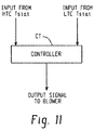
FIG. 11 is a schematic illustration of an exemplary controller for controlling a blower in accordance with the present disclosure. - With reference to
FIGS. 1-11 , and initially toFIGS. 1-3 anexemplary enclosure 10 in accordance with the present disclosure is schematically illustrated. Theexemplary enclosure 10 provides segregated cooling (e.g., low temperature/high temperature) within one enclosure, as well as an arc flash resistant design. As will be described in detail below, certain examples provide a 50 degree C TYPE 12 thermal packaging cooling system that segregates electronics into a cool side air compartment, power components and magnetics along with higher temp rated parts in a hot side air compartment, all within one cabinet enclosure. Certain examples also provide components in the enclosure (e.g., VFD, DC caps, etc.) to have no more than 5C rise above ambient in the cool side air compartment. - The
enclosure 10 generally comprises a housing H. The housing H defines an internal chamber C, which in the illustrated embodiment is divided by a partition P into two compartments - a low temperature compartment LTC (a first compartment) and a high temperature compartment HTC (e.g., a second compartment). It should be appreciated that the internal chamber C can be divided into additional compartments if desired or necessary. - The low temperature compartment LTC includes a variable frequency drive VFD, and other components configured to operate within the low temperature compartment LTC. In one example, the low temperature compartment LTC is configured to have no more than a 5 degree C temperature rise over ambient air during operation of the system. The high temperature compartment HTC includes magnetics and associated high power components. In some cases, portions of the same component may reside in both the low temperature compartment LTC and the high temperature compartment HTC (e.g., the VFD as seen in
FIG. 2 ). - Segregating the low temperature compartment LTC from the high temperature compartment HTC is desirable considering the Arrhenius Thermal Degradation Law relationship that component life, in general, decreases ½ for every 10 degree C rise in temperature. Thus, a low temperature compartment with sensitive electronics, if limited to a 5C rise, may see a 25% reduction in expected life. However, the same electronics in a high temperature compartment with magnetics and high power dissipating devices, may be subjected to a typical 20 degree C rise, considered as an optimal cost effective magnetic design. Thus, without thermal cooling segregation, the electronics would suffer a 75% reduction in expected life.
- As best seen in
FIG. 2 , theenclosure 10 includes a first intake vent V1 (three louvered openings shown in later drawings) to receive ambient air into the low temperature compartment LTC, second intake vents V2 (one vent on front and one vent on rear shown in later drawings) to receive ambient air into the high temperature compartment HTC, and a blower B to direct air from both the low temperature compartment LTC and the high temperature compartment HTC out of theenclosure 10. First and second cooling flow paths CP1 and CP2 extend between the vents V1 and V2, respectively, and an exhaust outlet of the blower B. It will be appreciated that any suitable number of intake vents V1 and V2 can be used without departing from the scope of the present disclosure. - In accordance with the present disclosure, cooling flow path CP1 of the low temperature compartment LTC is in fluid communication with the high temperature cooling flow path CP2 via one or more openings O or passageways extending across the partition P. The opening O allows air to exit the low temperature compartment LTC and enter the high temperature compartment at a location adjacent to the blower B, in an upper region of the high temperature compartment HTC. The blower B is configured to direct exhaust air from each of the low temperature compartment LTC and the high temperature compartment HTC out the top of the
enclosure 10. - As compared to other enclosure configurations, such as existing enclosures using a fan to blow air from the low temperature compartment LTC out the front (e.g., front door) or sides of the enclosure, or otherwise having upper vents on the sides of the enclosure where arc plasma can discharge in the event of an arc fault, the
enclosure 10 directs any arc plasma from the low temperature compartment LTC into the high temperature compartment HTC and/or out of the top ofenclosure 10 via theblower 10. - Other than vent VI, the low temperature compartment LTC is generally closed to the ambient except via the opening O and blower B. As such the single blower B directs air from both the low temperature compartment and the high temperature compartment LTC and HTC out of the
enclosure 10, and provides an improved exit location for potential arc flashes. - For example, as shown in
FIGS. 4 and5 , it will be appreciated that the housing H of theenclosure 10 is generally comprised of a plurality of panels (e.g., side panels SP, top panel TP, bottom panel BP) mounted to an internal frame structure F (side panel SP removed inFIGS. 4 and5 ). Theenclosure 10 further includes front and rear doors FD and RD (or panels) for permitting access to the interior compartments. As can be seen, the only openings in the front and rear doors FD and RD are the vents V1 and V2 for admitting cooling air into the respective low temperature compartment LTC and high temperature compartment HTC. - The
example enclosure 10 includes a large powerful TYPE 12 hot side blower B to pull air from the low temperature compartment LTC and the high temperature compartment HTC, and reduces costs by eliminating door venting and/or door mounted fans (e.g., the doors do not have an exhaust vent). Disclosed examples also facilitate meeting a less than 5 degree C rise for the VFD, electronics, low voltage power supply sensors (e.g., associated feedback voltage and current sensors), etc. inside the low temperature (cool) compartment LTC for high reliability and long life (since every 10C cuts life in half). - With additional reference to
FIGS. 6 and7 , theenclosure 10 of the present exemplary embodiment provides, in addition to the segregated cooling paths, improved arc flash resistance. It will be appreciated that the side panels SP and front and rear doors FD and RD have been removed from theenclosure 10 shown inFIGS. 6 and7 so that the arc flash paths of both the low temperature compartment LTC and high temperature compartment HTC can be illustrated. Arc flash incidents may possibly occur as a result of electrical components failing short across the incoming ac power line, limited only by the power source short circuit current interrupt rating. While circuit protection is opening as fast as possible within a few power line cycles, the arc created and expanding gas reaches extreme high temperatures and pressures and will find immediate available openings to exhaust. One objective of the exemplary cabinet design is to provide improved arc flash personnel protection as to re-direct the most likely arc path upwards and away from nearby personnel, where it can be dissipated safely as the expanding high temperature gases find the path of least resistance through the powerful roof mounted blower B. - In
FIG. 6 , the cool side arc flash path CFP1 is shown. Theenclosure 10 is configured such that an arc fault emanating from near vent V1 will travel upwardly through the low temperature compartment LTC, through the one or more openings O in partition P into the high temperature compartment HTC, and upward and out to the ambient environment through the blower B. As such, the cool side arc flash path CFP1 makes at least two 90 degree turns prior to entering the blower B. The blower B in this embodiment has a louvered vent LV facing towards the front/rear of theenclosure 10. - In
FIG. 7 , the hot side arc flash path CFP2 is shown. The enclosure is configured such that an arc fault emanating from near the bottom of theenclosure 10 will travel upwardly in the high temperature compartment HTC and out the blower B via louvered vent LV. It should be appreciated that terminal portions of both the cool side arc flash path CFP1 and the hot side arc flash path CFP2 extend in common from the upper portion of the high temperature compartment HTC out to ambient through the blower B.
Also shown inFIGS. 6 and7 , the top panel TP of theenclosure 10 in one example includes an entry/exit gasketed removable gland plate. An 18 pulse output isolation transformer and the VFD output sinewave filter inductors are also shown illustrated along with the 18 pulse diode rectifier and DC OUTPUT anode blocking diodes, as well as an AC input line reactor and the 18 pulse output isolation transformer.FIGS. 6 and7 also illustrate aremovable fan assembly 40 at the bottom of theenclosure 10 which blows input air through the sinewave filter inductors and the output isolation transformer for the 18 pulse diode rectifier which generates the variable dc voltage for electroplating. Further details of exemplary electric/electronics components that can be supported in the exemplary enclosures of the present disclosure are set forth inU.S. Patent Application Serial No. 15/465,110, filed March 21, 2017 -
FIGS. 8 and9 illustrate anotherexemplary enclosure 10' in accordance with the present disclosure wherein components previously described in connection withFIGS 1-7 are indicated with the same reference numerals denoted by a single "prime." For the sake of brevity, only features of theenclosure 10' that differ from theenclosure 10 will be described. In this alternative embodiment, the louvered vent LV' of the blower B' is arranged to exhaust to the sides of theenclosure 10' instead of on the front and back (e.g., as illustrated in the embodiment shown inFIGS. 4-7 ). -
FIG. 10 illustrates anotherexemplary enclosure 10" in accordance with the present disclosure wherein components previously described in connection withFIGS 1-7 are indicated with the same reference numerals denoted by a double "prime." For the sake of brevity, only features of theenclosure 10" that differ from theenclosure 10 will be described. The side panels and doors of theenclosure 10" are not illustrated inFIG. 9 so that the internal components of the enclosure can be seen. In this embodiment, theenclosure 10 is supported on a cable chamber CC". In addition, arc deflectors D" (e.g., arc resistant baffles) are installed behind each of the vents V1 and V2. The arc deflectors D" are configured to deflect any arc plasma that would otherwise travel out of vents V1 and/or V2 in the case of an arc fault. An exemplary arc resistant baffle is set forth in commonly-assignedU.S. Patent No. 7,778,013 issued on August 17, 2010 , the contents of which is incorporated herein by reference in its entirety. - Turning to
FIG. 11 , it should be understood that the blower of any of the above-described embodiments can be controlled to operate with a desired profile. To this end, thermostats can be mounted within or adjacent to one or both of the high temperature compartment and the low temperature compartment (seeFIG. 2 ). The thermostats can provide a signal to a controller CT that is configured to activate the blower at one or more speeds based at least in part on the signal received from one or both of the thermostats. The controller CT can be integral with the blower, or can be a standalone unit, or can be part of another system. It should be appreciated that, in some embodiments, the controller CT is optional, and that it is possible to directly control the blower with the thermostats. - In one configuration, the blower can be operated at a first speed when both of the thermostats are below their respective set-points. When at least one of the thermostats exceeds its set-point, the blower can then be operated at a second speed. In one example, the first speed is a low speed and the second speed is a high speed. A shutdown timer can be provided for running the blower for a certain time period after shutdown of the electrical/electronic components.
- In operation, the low temperature compartment LTC will likely rise above the set-point temperature before the high temperature compartment. However, by running the blower at a lower speed during at least a portion of the time, bearing life can be increased while blower noise is reduced.
- It will now be appreciated that the present disclosure sets forth an enclosure that limits exposure of personnel to arc flash hazards by redirecting any arc flash out the top of the enclosure, upward and away from personnel in the vicinity.
- In the preceding specification, various embodiments have been described with reference to the accompanying drawings. It will, however, be evident that various modifications and changes may be made thereto, and additional embodiments may be implemented, without departing from the broader scope of the invention as set forth in the claims that follow. The specification and drawings are accordingly to be regarded in an illustrative rather than restrictive sense.
-
-
Embodiment 1. An enclosure, comprising:- a first compartment to operate at a first controlled temperature range, the first compartment including a variable frequency drive;
- a second compartment to operate at a second controlled temperature range higher than the first controlled temperature range, the second compartment including magnetics and higher temperature rated components,
- a first intake vent to receive ambient air into the first compartment;
- a second intake vent to receive ambient air into the second compartment; and
- a blower to direct air from both the first and second compartments out of the enclosure;
- wherein ambient air received in the first compartment flows along a first cooling path extending from the first intake vent to the blower;
- wherein ambient air received in the second compartment flows along a second cooling path extending from the second intake vent to the blower; and
- wherein a terminal portion of the first flow path joins the second flow path prior to the blower.
- Embodiment 2. The enclosure of
embodiment 1, further comprising a partition at least partially separating the first compartment from the second compartment, and at least one opening in the partition through which the first flow path extends from the first compartment into the second compartment. - Embodiment 3. The enclosure of embodiment 2, wherein the at least one opening is at an upper portion of the partition adjacent a top panel of the enclosure.
- Embodiment 4. The enclosure of
embodiment 1, further comprising at least one door for accessing the first compartment. - Embodiment 5. The enclosure of
embodiment 1, wherein the at least one door includes the first intake vent, wherein the first intake vent is the only pathway to the ambient environment through the door. - Embodiment 6. The enclosure of
embodiment 1, wherein the blower is a TYPE 12, 50 degree C 2-speed blower. - Embodiment 7. The enclosure of
embodiment 1, wherein a first arc flash path of the first compartment extends between the first intake vent and the blower, the arc flash path making at least two 90 degree turns prior to the blower. - Embodiment 8. The enclosure of embodiment 7, wherein a second arc flash path of the second compartment extends between the second intake vent and the blower, the first arc flash path and the second arc flash path being coextensive within at least a portion of the second compartment.
- Embodiment 9. The enclosure of embodiment 8, wherein both the first arc flash path and the second arc flash path exit the enclosure through a top panel of the enclosure.
-
Embodiment 10. An enclosure for electrical equipment comprising:- a low temperature compartment to operate at a first controlled temperature range, the low temperature compartment configured to house a first set of associated electrical components;
- a high temperature compartment to operate at a second controlled temperature range higher than the first controlled temperature range, the high temperature compartment configured to house a second set of associated electrical components;
- a first intake vent to receive ambient air into the low temperature compartment;
- a second intake vent to receive ambient air into the high temperature compartment; and
- a blower to direct air from both the low temperature compartment and the high temperature compartment out of the enclosure;
- wherein ambient air entering the low temperature compartment flows along a first cooling path extending from the first intake vent to the blower;
- wherein ambient air entering the high temperature compartment flows along a second cooling path extending from the second intake vent to the blower; and
- wherein a terminal portion of the first flow path joins the second flow path prior to the blower.
- Embodiment 11. The enclosure of
embodiment 10, further comprising a partition at least partially separating the low temperature compartment from the high temperature compartment within the enclosure, and at least one opening in the partition through which the first flow path extends from the low temperature compartment into the high temperature compartment. - Embodiment 12. The enclosure of embodiment 11, wherein the at least one opening is at an upper portion of the partition adjacent a top panel of the enclosure.
- Embodiment 13. The enclosure of
embodiment 10, further comprising at least one door for accessing the first compartment. - Embodiment 14. The enclosure of embodiment 13, wherein the at least one door includes the first intake vent, wherein the first intake vent is the only pathway to the ambient environment through the door.
- Embodiment 15. The enclosure of
embodiment 10, wherein the blower is a TYPE 12, 50 degree C 2-speed blower. - Embodiment 16. The enclosure of
embodiment 10, wherein a first arc flash path of the low temperature compartment extends between the first intake vent and the blower, the arc flash path making at least two 90 degree turns prior to the blower. - Embodiment 17. The enclosure of embodiment 16, wherein a second arc flash path of the high temperature compartment extends between the second intake vent and the blower, the first arc flash path and the second arc flash path being coextensive within at least a portion of the second compartment.
- Embodiment 18. The enclosure of embodiment 18, wherein both the first arc flash path and the second arc flash path exit the enclosure through a top panel of the enclosure.
Claims (15)
- An enclosure, comprising:a first compartment to operate at a first controlled temperature range, the first compartment including a variable frequency drive;a second compartment to operate at a second controlled temperature range higher than the first controlled temperature range, the second compartment including magnetics and higher temperature rated components,a first intake vent to receive ambient air into the first compartment;a second intake vent to receive ambient air into the second compartment; anda blower to direct air from both the first and second compartments out of the enclosure;wherein ambient air received in the first compartment flows along a first cooling path extending from the first intake vent to the blower;wherein ambient air received in the second compartment flows along a second cooling path extending from the second intake vent to the blower; andwherein a terminal portion of the first flow path joins the second flow path prior to the blower.
- The enclosure of claim 1, further comprising a partition at least partially separating the first compartment from the second compartment, and at least one opening in the partition through which the first flow path extends from the first compartment into the second compartment.
- The enclosure of claim 2, wherein the at least one opening is at an upper portion of the partition adjacent a top panel of the enclosure.
- The enclosure of one of claims 1 to 3, further comprising at least one door for accessing the first compartment.
- The enclosure of one of claims 1 to 4, wherein the at least one door includes the first intake vent, wherein the first intake vent is the only pathway to the ambient environment through the door.
- The enclosure of one of claims 1 to 5, wherein the blower is a TYPE 12, 50 degree C 2-speed blower.
- The enclosure of one of claims 1 to 6, wherein a first arc flash path of the first compartment extends between the first intake vent and the blower, the arc flash path making at least two 90 degree turns prior to the blower.
- The enclosure of claim 7, wherein a second arc flash path of the second compartment extends between the second intake vent and the blower, the first arc flash path and the second arc flash path being coextensive within at least a portion of the second compartment; and/or
wherein both the first arc flash path and the second arc flash path exit the enclosure through a top panel of the enclosure. - An enclosure for electrical equipment comprising:a low temperature compartment to operate at a first controlled temperature range, the low temperature compartment configured to house a first set of associated electrical components;a high temperature compartment to operate at a second controlled temperature range higher than the first controlled temperature range, the high temperature compartment configured to house a second set of associated electrical components;a first intake vent to receive ambient air into the low temperature compartment;a second intake vent to receive ambient air into the high temperature compartment; anda blower to direct air from both the low temperature compartment and the high temperature compartment out of the enclosure;wherein ambient air entering the low temperature compartment flows along a first cooling path extending from the first intake vent to the blower;wherein ambient air entering the high temperature compartment flows along a second cooling path extending from the second intake vent to the blower; andwherein a terminal portion of the first flow path joins the second flow path prior to the blower.
- The enclosure of claim 9, further comprising a partition at least partially separating the low temperature compartment from the high temperature compartment within the enclosure, and at least one opening in the partition through which the first flow path extends from the low temperature compartment into the high temperature compartment; and/or
wherein the at least one opening is at an upper portion of the partition adjacent a top panel of the enclosure. - The enclosure of claim 9 or 10, further comprising at least one door for accessing the first compartment; and/or
wherein the at least one door includes the first intake vent, wherein the first intake vent is the only pathway to the ambient environment through the door. - The enclosure of one of claims 9 to 11, wherein the blower is a TYPE 12, 50 degree C 2-speed blower.
- The enclosure of one of claims 9 to 12, wherein a first arc flash path of the low temperature compartment extends between the first intake vent and the blower, the arc flash path making at least two 90 degree turns prior to the blower.
- The enclosure of claim 13, wherein a second arc flash path of the high temperature compartment extends between the second intake vent and the blower, the first arc flash path and the second arc flash path being coextensive within at least a portion of the second compartment.
- The enclosure of one of claims 9 to 14, wherein both the first arc flash path and the second arc flash path exit the enclosure through a top panel of the enclosure.
Applications Claiming Priority (2)
| Application Number | Priority Date | Filing Date | Title |
|---|---|---|---|
| US201762503246P | 2017-05-08 | 2017-05-08 | |
| US15/720,285 US10629396B2 (en) | 2017-05-08 | 2017-09-29 | Arc flash resistant enclosure with segregated cooling |
Publications (2)
| Publication Number | Publication Date |
|---|---|
| EP3402019A1 true EP3402019A1 (en) | 2018-11-14 |
| EP3402019B1 EP3402019B1 (en) | 2021-03-17 |
Family
ID=62152347
Family Applications (1)
| Application Number | Title | Priority Date | Filing Date |
|---|---|---|---|
| EP18171181.3A Active EP3402019B1 (en) | 2017-05-08 | 2018-05-08 | Arc flash resistant enclosure with segregated cooling |
Country Status (3)
| Country | Link |
|---|---|
| US (1) | US10629396B2 (en) |
| EP (1) | EP3402019B1 (en) |
| CN (1) | CN108882618B (en) |
Families Citing this family (12)
| Publication number | Priority date | Publication date | Assignee | Title |
|---|---|---|---|---|
| US10617043B2 (en) * | 2018-02-02 | 2020-04-07 | Siemens Aktiengesellschaft | Integrated air cooling and arc resistant system for medium voltage drive |
| US11245259B2 (en) * | 2018-08-30 | 2022-02-08 | Delta Electronics, Inc. | Power supply system |
| US10644484B2 (en) * | 2018-09-06 | 2020-05-05 | Toshiba International Corporation | Arc resistant exhaust and intake for drives and switchgear |
| JP6809715B2 (en) * | 2018-11-15 | 2021-01-06 | Necプラットフォームズ株式会社 | Electronics |
| US20210117592A1 (en) * | 2019-10-18 | 2021-04-22 | Technologies Dual-Ade Inc. | Method of designing a switchgear with arc-flash simulation and energy transmission thereof |
| CN112751473B (en) | 2019-10-31 | 2021-11-05 | 台达电子企业管理(上海)有限公司 | Power module |
| CN112750607A (en) | 2019-10-31 | 2021-05-04 | 台达电子企业管理(上海)有限公司 | Transformer and power module with same |
| CN112821722B (en) * | 2019-10-31 | 2022-07-19 | 台达电子企业管理(上海)有限公司 | Power conversion system |
| US11469575B2 (en) * | 2020-01-23 | 2022-10-11 | Vertiv Corporation | Airflow channel power distribution equipment cabinet |
| US10784660B1 (en) * | 2020-03-11 | 2020-09-22 | Siemens Industry, Inc. | Enhancing an auxiliary compartment of a modular bucket assembly in an arc resistant switchgear |
| CN111509570B (en) * | 2020-04-20 | 2021-08-03 | 山东上品电气工程有限公司 | Dustproof electric power cabinet |
| US11967845B2 (en) * | 2021-08-11 | 2024-04-23 | Benchmark Craftsman Inc. | Secured cabinet for charging portable batteries |
Citations (5)
| Publication number | Priority date | Publication date | Assignee | Title |
|---|---|---|---|---|
| US20050276017A1 (en) * | 2004-06-10 | 2005-12-15 | Farid Aziz | Common plenum and air intake airflow management for telecom equipment |
| US20100159816A1 (en) * | 2008-12-23 | 2010-06-24 | International Business Machines Corporation | Converging segments cooling |
| US7778013B2 (en) | 2005-10-28 | 2010-08-17 | Rockwell Automation Technologies, Inc. | Arc resistant baffle for reducing arc-flash energy in an electrical enclosure |
| US20120014063A1 (en) * | 2010-07-16 | 2012-01-19 | Rockwell Automation Technologies, Inc. | Heat sink cooling arrangement for multiple power electronic circuits |
| US20140260397A1 (en) * | 2013-03-12 | 2014-09-18 | Schneider Electric Industries Sas | Electrical cabinet with improved heat dissipation |
Family Cites Families (45)
| Publication number | Priority date | Publication date | Assignee | Title |
|---|---|---|---|---|
| US4602200A (en) | 1985-02-26 | 1986-07-22 | General Electric Company | Alternating current motor drive having current filter |
| US5623191A (en) | 1995-04-12 | 1997-04-22 | Allen-Bradley Company, Inc. | Circuit board architecture for a motor controller |
| JP3613010B2 (en) * | 1998-06-23 | 2005-01-26 | セイコーエプソン株式会社 | Projection display |
| US6094346A (en) * | 1998-12-29 | 2000-07-25 | Intel Corporation | Processor assembly cooling cell |
| US6208537B1 (en) | 1999-09-28 | 2001-03-27 | Rockwell Technologies, Llc | Series resonant sinewave output filter and design methodology |
| US6440567B1 (en) * | 2000-03-31 | 2002-08-27 | Isola Laminate Systems Corp. | Halogen free flame retardant adhesive resin coated composite |
| US6335872B1 (en) | 2000-07-14 | 2002-01-01 | Rockwell Automation Technologies, Inc. | Nine-phase transformer |
| US6198647B1 (en) | 2000-07-28 | 2001-03-06 | Rockwell Technologies, Llc | Twelve-phase transformer configuration |
| US6400567B1 (en) * | 2000-10-19 | 2002-06-04 | Fujitsu Network Communications, Inc. | Equipment enclosure having separate compartments cooled by separate cooling airflows |
| US6549434B2 (en) | 2001-09-20 | 2003-04-15 | Rockwell Automation Technologies, Inc. | Harmonic mitigating method and apparatus |
| JP2003339164A (en) | 2002-05-22 | 2003-11-28 | Hitachi Industrial Equipment Systems Co Ltd | Switching power circuit and inverter device |
| JP3957206B2 (en) | 2003-06-26 | 2007-08-15 | イーエムシー株式会社 | Noise filter for safety ground wire and electronic device equipped with the same |
| US6940735B2 (en) | 2003-11-14 | 2005-09-06 | Ballard Power Systems Corporation | Power converter system |
| US7375490B2 (en) | 2004-09-14 | 2008-05-20 | Siemens Energy & Automation, Inc. | Methods for managing electrical power |
| US7626836B2 (en) | 2005-10-26 | 2009-12-01 | Rockwell Automation Technologies, Inc. | Method and apparatus for adjustable voltage/adjustable frequency inverter control |
| US7633759B2 (en) | 2006-03-10 | 2009-12-15 | Eaton Power Quality Corporation | Power module connection assemblies and universal power supplies and methods including the same |
| US7535738B2 (en) | 2006-08-23 | 2009-05-19 | Rockwell Automation Technologies, Inc. | Method and apparatus including multi-drive configurations for medium voltage loads |
| FI121613B (en) | 2006-12-21 | 2011-01-31 | Abb Oy | Method and system in connection with a motor fed by a voltage converter |
| US7825621B2 (en) | 2007-08-28 | 2010-11-02 | Rockwell Automation Technologies, Inc. | Junction temperature reduction for three phase inverters modules |
| US7826985B2 (en) | 2008-05-02 | 2010-11-02 | Rockwell Automation Technologies, Inc. | Power module life estimation fatigue function |
| US8125304B2 (en) | 2008-09-30 | 2012-02-28 | Rockwell Automation Technologies, Inc. | Power electronic module with an improved choke and methods of making same |
| US8148929B2 (en) | 2008-09-30 | 2012-04-03 | Rockwell Automation Technologies, Inc. | Power electronic module IGBT protection method and system |
| US7830036B2 (en) | 2008-09-30 | 2010-11-09 | Rockwell Automation Technologies, Inc. | Power electronic module pre-charge system and method |
| US8299732B2 (en) | 2009-01-15 | 2012-10-30 | Rockwell Automation Technologies, Inc. | Power conversion system and method |
| US8508181B2 (en) | 2009-06-30 | 2013-08-13 | Eaton Corporation | Adjustable frequency drive and system |
| US8130501B2 (en) | 2009-06-30 | 2012-03-06 | Teco-Westinghouse Motor Company | Pluggable power cell for an inverter |
| US8243481B2 (en) | 2009-11-04 | 2012-08-14 | Rockwell Automation Technologies, Inc. | Power transformer and power converter incorporating same |
| US8339820B2 (en) | 2009-11-04 | 2012-12-25 | Rockwell Automation Technologies, Inc. | Thirty-six pulse power transformer and power converter incorporating same |
| US8188693B2 (en) | 2009-11-04 | 2012-05-29 | Rockwell Automation Technologies, Inc. | DC bus boost method and system for regenerative brake |
| US8433528B2 (en) | 2009-12-18 | 2013-04-30 | Rockwell Automation Technologies, Inc. | Ground fault detection system and method |
| US8471516B2 (en) | 2010-05-24 | 2013-06-25 | Rockwell Automation Technologies, Inc. | Adjustable speed drive lifetime improvement method |
| US8432052B2 (en) | 2010-05-27 | 2013-04-30 | Rockwell Automation Technologies, Inc. | Wind power converter system with grid side reactive power control |
| US8736091B2 (en) | 2010-06-18 | 2014-05-27 | Rockwell Automation Technologies, Inc. | Converter lifetime improvement method for doubly fed induction generator |
| US8456807B2 (en) | 2010-07-16 | 2013-06-04 | Rockwell Automation Technologies, Inc. | Common mode magnetic device for bus structure |
| JP5510750B2 (en) | 2011-04-18 | 2014-06-04 | 株式会社安川電機 | Power converter and reactor |
| KR20130039612A (en) | 2011-10-12 | 2013-04-22 | 엘에스산전 주식회사 | Regenerative medium voltage inverter |
| US8816625B2 (en) | 2011-10-27 | 2014-08-26 | Rockwell Automation Technologies, Inc. | Integrated regenerative AC drive with solid state precharging |
| US8816631B2 (en) | 2012-03-13 | 2014-08-26 | Rockwell Automation Technologies, Inc. | Apparatus and method for energy efficient motor drive standby operation |
| US9054599B2 (en) | 2012-03-15 | 2015-06-09 | Rockwell Automation Technologies, Inc. | Power converter and integrated DC choke therefor |
| US9237663B2 (en) | 2012-04-06 | 2016-01-12 | Rockwell Automation Technologies, Inc. | Methods and apparatus for mitigating arc flash incident energy in motor control devices |
| FR2992117B1 (en) | 2012-06-19 | 2014-06-13 | Converteam Technology Ltd | CHARGE SUPPLY SYSTEM COMPRISING A CONVERTER CONNECTED TO A NETWORK AND A TRANSFORMER CONNECTED IN PARALLEL OF THE CONVERTER TO LIMIT HOMOPOLAR CURRENT, AND DRIVE CHAIN COMPRISING SUCH A SYSTEM |
| CN202856646U (en) | 2012-08-23 | 2013-04-03 | 天津瑞能电气有限公司 | Inverter cabinet with great heat exchanging capability |
| CN105580502B (en) | 2012-11-06 | 2018-12-21 | 西门子公司 | For mitigating the arc fault access of the arc fault in outer casing of power supply |
| US9654021B2 (en) | 2013-10-09 | 2017-05-16 | Rockwell Automation Technologies, Inc. | Multifunction power converter with option for integrated magnetics |
| JP6627438B2 (en) * | 2015-11-10 | 2020-01-08 | 富士通株式会社 | Cooling device and information processing device |
-
2017
- 2017-09-29 US US15/720,285 patent/US10629396B2/en active Active
-
2018
- 2018-05-02 CN CN201810410165.4A patent/CN108882618B/en active Active
- 2018-05-08 EP EP18171181.3A patent/EP3402019B1/en active Active
Patent Citations (5)
| Publication number | Priority date | Publication date | Assignee | Title |
|---|---|---|---|---|
| US20050276017A1 (en) * | 2004-06-10 | 2005-12-15 | Farid Aziz | Common plenum and air intake airflow management for telecom equipment |
| US7778013B2 (en) | 2005-10-28 | 2010-08-17 | Rockwell Automation Technologies, Inc. | Arc resistant baffle for reducing arc-flash energy in an electrical enclosure |
| US20100159816A1 (en) * | 2008-12-23 | 2010-06-24 | International Business Machines Corporation | Converging segments cooling |
| US20120014063A1 (en) * | 2010-07-16 | 2012-01-19 | Rockwell Automation Technologies, Inc. | Heat sink cooling arrangement for multiple power electronic circuits |
| US20140260397A1 (en) * | 2013-03-12 | 2014-09-18 | Schneider Electric Industries Sas | Electrical cabinet with improved heat dissipation |
Also Published As
| Publication number | Publication date |
|---|---|
| US20180323022A1 (en) | 2018-11-08 |
| US10629396B2 (en) | 2020-04-21 |
| EP3402019B1 (en) | 2021-03-17 |
| CN108882618B (en) | 2020-05-12 |
| CN108882618A (en) | 2018-11-23 |
Similar Documents
| Publication | Publication Date | Title |
|---|---|---|
| EP3402019B1 (en) | Arc flash resistant enclosure with segregated cooling | |
| EP2603068B1 (en) | Device and method using induction to improve natural convection cooling | |
| US20070097604A1 (en) | Arc resistant baffle for reducing arc-flash energy in an electrical enclosure | |
| JP4979767B2 (en) | Metal closed switchgear | |
| US8325478B2 (en) | Cooling duct attachment and sealing for a motor drive | |
| KR101907718B1 (en) | Elevator shaft closure having an elevator control assembly | |
| US20140260397A1 (en) | Electrical cabinet with improved heat dissipation | |
| EP3493388B1 (en) | Power conversion device | |
| EP3483994A1 (en) | Isolation and exhaust system for an electrical enclosure | |
| JP2007507090A (en) | Equipment and network cabinet cooling system, and equipment and network cabinet cooling method | |
| CN111670613B (en) | Integrated air cooling and arc resistant system for medium voltage drives | |
| US20140138068A1 (en) | Cooling System | |
| EP2879475A1 (en) | Solar inverter | |
| US9271421B2 (en) | Adapter for arc resistant motor control center | |
| JPWO2015186208A1 (en) | Power equipment | |
| KR20150038477A (en) | Switchgear | |
| JP7002675B2 (en) | Gas insulation switchgear | |
| EP3474398B1 (en) | Electrical unit for a motor control center with improved ventilation protection | |
| JP5883774B2 (en) | Control device and control device cooling method | |
| US11304330B2 (en) | Low-voltage switching device having a defined cooling arrangement | |
| BR102018009114A2 (en) | OFFICE, AND OFFICE FOR ELECTRICAL EQUIPMENT | |
| KR20180009922A (en) | Explosion proof type inverter apparatus | |
| CN215222711U (en) | Mining industry is with heat dissipation electronic box | |
| CN210982645U (en) | Electrical cabinet fault monitoring device capable of being positioned quickly | |
| CN209913297U (en) | Safe type power cabinet |
Legal Events
| Date | Code | Title | Description |
|---|---|---|---|
| PUAI | Public reference made under article 153(3) epc to a published international application that has entered the european phase |
Free format text: ORIGINAL CODE: 0009012 |
|
| STAA | Information on the status of an ep patent application or granted ep patent |
Free format text: STATUS: THE APPLICATION HAS BEEN PUBLISHED |
|
| AK | Designated contracting states |
Kind code of ref document: A1 Designated state(s): AL AT BE BG CH CY CZ DE DK EE ES FI FR GB GR HR HU IE IS IT LI LT LU LV MC MK MT NL NO PL PT RO RS SE SI SK SM TR |
|
| AX | Request for extension of the european patent |
Extension state: BA ME |
|
| STAA | Information on the status of an ep patent application or granted ep patent |
Free format text: STATUS: REQUEST FOR EXAMINATION WAS MADE |
|
| 17P | Request for examination filed |
Effective date: 20190502 |
|
| RBV | Designated contracting states (corrected) |
Designated state(s): AL AT BE BG CH CY CZ DE DK EE ES FI FR GB GR HR HU IE IS IT LI LT LU LV MC MK MT NL NO PL PT RO RS SE SI SK SM TR |
|
| GRAP | Despatch of communication of intention to grant a patent |
Free format text: ORIGINAL CODE: EPIDOSNIGR1 |
|
| STAA | Information on the status of an ep patent application or granted ep patent |
Free format text: STATUS: GRANT OF PATENT IS INTENDED |
|
| INTG | Intention to grant announced |
Effective date: 20201008 |
|
| GRAS | Grant fee paid |
Free format text: ORIGINAL CODE: EPIDOSNIGR3 |
|
| GRAA | (expected) grant |
Free format text: ORIGINAL CODE: 0009210 |
|
| STAA | Information on the status of an ep patent application or granted ep patent |
Free format text: STATUS: THE PATENT HAS BEEN GRANTED |
|
| AK | Designated contracting states |
Kind code of ref document: B1 Designated state(s): AL AT BE BG CH CY CZ DE DK EE ES FI FR GB GR HR HU IE IS IT LI LT LU LV MC MK MT NL NO PL PT RO RS SE SI SK SM TR |
|
| REG | Reference to a national code |
Ref country code: GB Ref legal event code: FG4D |
|
| REG | Reference to a national code |
Ref country code: CH Ref legal event code: EP |
|
| REG | Reference to a national code |
Ref country code: DE Ref legal event code: R096 Ref document number: 602018013920 Country of ref document: DE |
|
| REG | Reference to a national code |
Ref country code: IE Ref legal event code: FG4D |
|
| REG | Reference to a national code |
Ref country code: AT Ref legal event code: REF Ref document number: 1373125 Country of ref document: AT Kind code of ref document: T Effective date: 20210415 |
|
| REG | Reference to a national code |
Ref country code: LT Ref legal event code: MG9D |
|
| PG25 | Lapsed in a contracting state [announced via postgrant information from national office to epo] |
Ref country code: NO Free format text: LAPSE BECAUSE OF FAILURE TO SUBMIT A TRANSLATION OF THE DESCRIPTION OR TO PAY THE FEE WITHIN THE PRESCRIBED TIME-LIMIT Effective date: 20210617 Ref country code: HR Free format text: LAPSE BECAUSE OF FAILURE TO SUBMIT A TRANSLATION OF THE DESCRIPTION OR TO PAY THE FEE WITHIN THE PRESCRIBED TIME-LIMIT Effective date: 20210317 Ref country code: FI Free format text: LAPSE BECAUSE OF FAILURE TO SUBMIT A TRANSLATION OF THE DESCRIPTION OR TO PAY THE FEE WITHIN THE PRESCRIBED TIME-LIMIT Effective date: 20210317 Ref country code: GR Free format text: LAPSE BECAUSE OF FAILURE TO SUBMIT A TRANSLATION OF THE DESCRIPTION OR TO PAY THE FEE WITHIN THE PRESCRIBED TIME-LIMIT Effective date: 20210618 Ref country code: BG Free format text: LAPSE BECAUSE OF FAILURE TO SUBMIT A TRANSLATION OF THE DESCRIPTION OR TO PAY THE FEE WITHIN THE PRESCRIBED TIME-LIMIT Effective date: 20210617 |
|
| REG | Reference to a national code |
Ref country code: AT Ref legal event code: MK05 Ref document number: 1373125 Country of ref document: AT Kind code of ref document: T Effective date: 20210317 |
|
| REG | Reference to a national code |
Ref country code: NL Ref legal event code: MP Effective date: 20210317 |
|
| PG25 | Lapsed in a contracting state [announced via postgrant information from national office to epo] |
Ref country code: LV Free format text: LAPSE BECAUSE OF FAILURE TO SUBMIT A TRANSLATION OF THE DESCRIPTION OR TO PAY THE FEE WITHIN THE PRESCRIBED TIME-LIMIT Effective date: 20210317 Ref country code: RS Free format text: LAPSE BECAUSE OF FAILURE TO SUBMIT A TRANSLATION OF THE DESCRIPTION OR TO PAY THE FEE WITHIN THE PRESCRIBED TIME-LIMIT Effective date: 20210317 Ref country code: SE Free format text: LAPSE BECAUSE OF FAILURE TO SUBMIT A TRANSLATION OF THE DESCRIPTION OR TO PAY THE FEE WITHIN THE PRESCRIBED TIME-LIMIT Effective date: 20210317 |
|
| PG25 | Lapsed in a contracting state [announced via postgrant information from national office to epo] |
Ref country code: NL Free format text: LAPSE BECAUSE OF FAILURE TO SUBMIT A TRANSLATION OF THE DESCRIPTION OR TO PAY THE FEE WITHIN THE PRESCRIBED TIME-LIMIT Effective date: 20210317 |
|
| PG25 | Lapsed in a contracting state [announced via postgrant information from national office to epo] |
Ref country code: SM Free format text: LAPSE BECAUSE OF FAILURE TO SUBMIT A TRANSLATION OF THE DESCRIPTION OR TO PAY THE FEE WITHIN THE PRESCRIBED TIME-LIMIT Effective date: 20210317 Ref country code: AT Free format text: LAPSE BECAUSE OF FAILURE TO SUBMIT A TRANSLATION OF THE DESCRIPTION OR TO PAY THE FEE WITHIN THE PRESCRIBED TIME-LIMIT Effective date: 20210317 Ref country code: EE Free format text: LAPSE BECAUSE OF FAILURE TO SUBMIT A TRANSLATION OF THE DESCRIPTION OR TO PAY THE FEE WITHIN THE PRESCRIBED TIME-LIMIT Effective date: 20210317 Ref country code: CZ Free format text: LAPSE BECAUSE OF FAILURE TO SUBMIT A TRANSLATION OF THE DESCRIPTION OR TO PAY THE FEE WITHIN THE PRESCRIBED TIME-LIMIT Effective date: 20210317 Ref country code: LT Free format text: LAPSE BECAUSE OF FAILURE TO SUBMIT A TRANSLATION OF THE DESCRIPTION OR TO PAY THE FEE WITHIN THE PRESCRIBED TIME-LIMIT Effective date: 20210317 |
|
| PG25 | Lapsed in a contracting state [announced via postgrant information from national office to epo] |
Ref country code: IS Free format text: LAPSE BECAUSE OF FAILURE TO SUBMIT A TRANSLATION OF THE DESCRIPTION OR TO PAY THE FEE WITHIN THE PRESCRIBED TIME-LIMIT Effective date: 20210717 Ref country code: PT Free format text: LAPSE BECAUSE OF FAILURE TO SUBMIT A TRANSLATION OF THE DESCRIPTION OR TO PAY THE FEE WITHIN THE PRESCRIBED TIME-LIMIT Effective date: 20210719 Ref country code: PL Free format text: LAPSE BECAUSE OF FAILURE TO SUBMIT A TRANSLATION OF THE DESCRIPTION OR TO PAY THE FEE WITHIN THE PRESCRIBED TIME-LIMIT Effective date: 20210317 Ref country code: RO Free format text: LAPSE BECAUSE OF FAILURE TO SUBMIT A TRANSLATION OF THE DESCRIPTION OR TO PAY THE FEE WITHIN THE PRESCRIBED TIME-LIMIT Effective date: 20210317 Ref country code: SK Free format text: LAPSE BECAUSE OF FAILURE TO SUBMIT A TRANSLATION OF THE DESCRIPTION OR TO PAY THE FEE WITHIN THE PRESCRIBED TIME-LIMIT Effective date: 20210317 |
|
| REG | Reference to a national code |
Ref country code: DE Ref legal event code: R097 Ref document number: 602018013920 Country of ref document: DE |
|
| REG | Reference to a national code |
Ref country code: CH Ref legal event code: PL |
|
| PLBE | No opposition filed within time limit |
Free format text: ORIGINAL CODE: 0009261 |
|
| STAA | Information on the status of an ep patent application or granted ep patent |
Free format text: STATUS: NO OPPOSITION FILED WITHIN TIME LIMIT |
|
| PG25 | Lapsed in a contracting state [announced via postgrant information from national office to epo] |
Ref country code: LI Free format text: LAPSE BECAUSE OF NON-PAYMENT OF DUE FEES Effective date: 20210531 Ref country code: MC Free format text: LAPSE BECAUSE OF FAILURE TO SUBMIT A TRANSLATION OF THE DESCRIPTION OR TO PAY THE FEE WITHIN THE PRESCRIBED TIME-LIMIT Effective date: 20210317 Ref country code: LU Free format text: LAPSE BECAUSE OF NON-PAYMENT OF DUE FEES Effective date: 20210508 Ref country code: CH Free format text: LAPSE BECAUSE OF NON-PAYMENT OF DUE FEES Effective date: 20210531 Ref country code: DK Free format text: LAPSE BECAUSE OF FAILURE TO SUBMIT A TRANSLATION OF THE DESCRIPTION OR TO PAY THE FEE WITHIN THE PRESCRIBED TIME-LIMIT Effective date: 20210317 Ref country code: AL Free format text: LAPSE BECAUSE OF FAILURE TO SUBMIT A TRANSLATION OF THE DESCRIPTION OR TO PAY THE FEE WITHIN THE PRESCRIBED TIME-LIMIT Effective date: 20210317 Ref country code: ES Free format text: LAPSE BECAUSE OF FAILURE TO SUBMIT A TRANSLATION OF THE DESCRIPTION OR TO PAY THE FEE WITHIN THE PRESCRIBED TIME-LIMIT Effective date: 20210317 |
|
| REG | Reference to a national code |
Ref country code: BE Ref legal event code: MM Effective date: 20210531 |
|
| 26N | No opposition filed |
Effective date: 20211220 |
|
| PG25 | Lapsed in a contracting state [announced via postgrant information from national office to epo] |
Ref country code: SI Free format text: LAPSE BECAUSE OF FAILURE TO SUBMIT A TRANSLATION OF THE DESCRIPTION OR TO PAY THE FEE WITHIN THE PRESCRIBED TIME-LIMIT Effective date: 20210317 |
|
| PG25 | Lapsed in a contracting state [announced via postgrant information from national office to epo] |
Ref country code: IT Free format text: LAPSE BECAUSE OF FAILURE TO SUBMIT A TRANSLATION OF THE DESCRIPTION OR TO PAY THE FEE WITHIN THE PRESCRIBED TIME-LIMIT Effective date: 20210317 Ref country code: IE Free format text: LAPSE BECAUSE OF NON-PAYMENT OF DUE FEES Effective date: 20210508 |
|
| PG25 | Lapsed in a contracting state [announced via postgrant information from national office to epo] |
Ref country code: IS Free format text: LAPSE BECAUSE OF FAILURE TO SUBMIT A TRANSLATION OF THE DESCRIPTION OR TO PAY THE FEE WITHIN THE PRESCRIBED TIME-LIMIT Effective date: 20210717 |
|
| PG25 | Lapsed in a contracting state [announced via postgrant information from national office to epo] |
Ref country code: BE Free format text: LAPSE BECAUSE OF NON-PAYMENT OF DUE FEES Effective date: 20210531 |
|
| P01 | Opt-out of the competence of the unified patent court (upc) registered |
Effective date: 20230404 |
|
| PG25 | Lapsed in a contracting state [announced via postgrant information from national office to epo] |
Ref country code: CY Free format text: LAPSE BECAUSE OF FAILURE TO SUBMIT A TRANSLATION OF THE DESCRIPTION OR TO PAY THE FEE WITHIN THE PRESCRIBED TIME-LIMIT Effective date: 20210317 |
|
| PG25 | Lapsed in a contracting state [announced via postgrant information from national office to epo] |
Ref country code: HU Free format text: LAPSE BECAUSE OF FAILURE TO SUBMIT A TRANSLATION OF THE DESCRIPTION OR TO PAY THE FEE WITHIN THE PRESCRIBED TIME-LIMIT; INVALID AB INITIO Effective date: 20180508 |
|
| PGFP | Annual fee paid to national office [announced via postgrant information from national office to epo] |
Ref country code: FR Payment date: 20230420 Year of fee payment: 6 Ref country code: DE Payment date: 20230419 Year of fee payment: 6 |
|
| PGFP | Annual fee paid to national office [announced via postgrant information from national office to epo] |
Ref country code: GB Payment date: 20230420 Year of fee payment: 6 |