EP3401978A1 - Method for producing an electrode assembly for a battery cell and battery cell - Google Patents
Method for producing an electrode assembly for a battery cell and battery cell Download PDFInfo
- Publication number
- EP3401978A1 EP3401978A1 EP17170039.6A EP17170039A EP3401978A1 EP 3401978 A1 EP3401978 A1 EP 3401978A1 EP 17170039 A EP17170039 A EP 17170039A EP 3401978 A1 EP3401978 A1 EP 3401978A1
- Authority
- EP
- European Patent Office
- Prior art keywords
- foil
- anode
- separator
- whereat
- laser beam
- Prior art date
- Legal status (The legal status is an assumption and is not a legal conclusion. Google has not performed a legal analysis and makes no representation as to the accuracy of the status listed.)
- Granted
Links
Images



Classifications
-
- H—ELECTRICITY
- H01—ELECTRIC ELEMENTS
- H01M—PROCESSES OR MEANS, e.g. BATTERIES, FOR THE DIRECT CONVERSION OF CHEMICAL ENERGY INTO ELECTRICAL ENERGY
- H01M50/00—Constructional details or processes of manufacture of the non-active parts of electrochemical cells other than fuel cells, e.g. hybrid cells
- H01M50/40—Separators; Membranes; Diaphragms; Spacing elements inside cells
- H01M50/46—Separators, membranes or diaphragms characterised by their combination with electrodes
-
- H—ELECTRICITY
- H01—ELECTRIC ELEMENTS
- H01M—PROCESSES OR MEANS, e.g. BATTERIES, FOR THE DIRECT CONVERSION OF CHEMICAL ENERGY INTO ELECTRICAL ENERGY
- H01M50/00—Constructional details or processes of manufacture of the non-active parts of electrochemical cells other than fuel cells, e.g. hybrid cells
- H01M50/40—Separators; Membranes; Diaphragms; Spacing elements inside cells
- H01M50/409—Separators, membranes or diaphragms characterised by the material
- H01M50/449—Separators, membranes or diaphragms characterised by the material having a layered structure
- H01M50/451—Separators, membranes or diaphragms characterised by the material having a layered structure comprising layers of only organic material and layers containing inorganic material
-
- H—ELECTRICITY
- H01—ELECTRIC ELEMENTS
- H01M—PROCESSES OR MEANS, e.g. BATTERIES, FOR THE DIRECT CONVERSION OF CHEMICAL ENERGY INTO ELECTRICAL ENERGY
- H01M10/00—Secondary cells; Manufacture thereof
- H01M10/05—Accumulators with non-aqueous electrolyte
- H01M10/058—Construction or manufacture
- H01M10/0585—Construction or manufacture of accumulators having only flat construction elements, i.e. flat positive electrodes, flat negative electrodes and flat separators
-
- H—ELECTRICITY
- H01—ELECTRIC ELEMENTS
- H01M—PROCESSES OR MEANS, e.g. BATTERIES, FOR THE DIRECT CONVERSION OF CHEMICAL ENERGY INTO ELECTRICAL ENERGY
- H01M4/00—Electrodes
- H01M4/02—Electrodes composed of, or comprising, active material
- H01M4/13—Electrodes for accumulators with non-aqueous electrolyte, e.g. for lithium-accumulators; Processes of manufacture thereof
- H01M4/133—Electrodes based on carbonaceous material, e.g. graphite-intercalation compounds or CFx
-
- H—ELECTRICITY
- H01—ELECTRIC ELEMENTS
- H01M—PROCESSES OR MEANS, e.g. BATTERIES, FOR THE DIRECT CONVERSION OF CHEMICAL ENERGY INTO ELECTRICAL ENERGY
- H01M50/00—Constructional details or processes of manufacture of the non-active parts of electrochemical cells other than fuel cells, e.g. hybrid cells
- H01M50/40—Separators; Membranes; Diaphragms; Spacing elements inside cells
- H01M50/403—Manufacturing processes of separators, membranes or diaphragms
-
- H—ELECTRICITY
- H01—ELECTRIC ELEMENTS
- H01M—PROCESSES OR MEANS, e.g. BATTERIES, FOR THE DIRECT CONVERSION OF CHEMICAL ENERGY INTO ELECTRICAL ENERGY
- H01M10/00—Secondary cells; Manufacture thereof
- H01M10/05—Accumulators with non-aqueous electrolyte
- H01M10/052—Li-accumulators
- H01M10/0525—Rocking-chair batteries, i.e. batteries with lithium insertion or intercalation in both electrodes; Lithium-ion batteries
-
- H—ELECTRICITY
- H01—ELECTRIC ELEMENTS
- H01M—PROCESSES OR MEANS, e.g. BATTERIES, FOR THE DIRECT CONVERSION OF CHEMICAL ENERGY INTO ELECTRICAL ENERGY
- H01M2220/00—Batteries for particular applications
- H01M2220/20—Batteries in motive systems, e.g. vehicle, ship, plane
-
- Y—GENERAL TAGGING OF NEW TECHNOLOGICAL DEVELOPMENTS; GENERAL TAGGING OF CROSS-SECTIONAL TECHNOLOGIES SPANNING OVER SEVERAL SECTIONS OF THE IPC; TECHNICAL SUBJECTS COVERED BY FORMER USPC CROSS-REFERENCE ART COLLECTIONS [XRACs] AND DIGESTS
- Y02—TECHNOLOGIES OR APPLICATIONS FOR MITIGATION OR ADAPTATION AGAINST CLIMATE CHANGE
- Y02E—REDUCTION OF GREENHOUSE GAS [GHG] EMISSIONS, RELATED TO ENERGY GENERATION, TRANSMISSION OR DISTRIBUTION
- Y02E60/00—Enabling technologies; Technologies with a potential or indirect contribution to GHG emissions mitigation
- Y02E60/10—Energy storage using batteries
-
- Y—GENERAL TAGGING OF NEW TECHNOLOGICAL DEVELOPMENTS; GENERAL TAGGING OF CROSS-SECTIONAL TECHNOLOGIES SPANNING OVER SEVERAL SECTIONS OF THE IPC; TECHNICAL SUBJECTS COVERED BY FORMER USPC CROSS-REFERENCE ART COLLECTIONS [XRACs] AND DIGESTS
- Y02—TECHNOLOGIES OR APPLICATIONS FOR MITIGATION OR ADAPTATION AGAINST CLIMATE CHANGE
- Y02P—CLIMATE CHANGE MITIGATION TECHNOLOGIES IN THE PRODUCTION OR PROCESSING OF GOODS
- Y02P70/00—Climate change mitigation technologies in the production process for final industrial or consumer products
- Y02P70/50—Manufacturing or production processes characterised by the final manufactured product
Definitions
- the invention relates to a method for producing an electrode assembly for a battery cell, in particular for a lithium ion battery cell, comprising an anode foil, a first separator foil, a cathode foil and a second separator foil.
- the invention also relates to a battery cell that comprises at least one electrode assembly according to the invention.
- Batteries change chemical energy into electrical energy.
- rechargeable batteries are known that can be charged and discharged several times.
- Batteries or battery modules comprise several battery cells that are connected electrically in series or in parallel.
- lithium ion battery cells are used in rechargeable batteries or battery systems.
- Lithium ion battery cells have a relatively high energy density.
- Lithium ion battery cells are used for instance in motor vehicles, in particular in electric vehicles (EV), in hybrid electric vehicles (HEV) and in plug-in hybrid vehicles (PHEV).
- Lithium ion battery cells may comprise one or more electrode assemblies.
- Electrode assemblies have a positive electrode called cathode and a negative electrode called anode.
- the anode and the cathode are separated from one another by means of a separator.
- the electrodes of the battery cell can be formed like foils and wound with interposition of the separator to form an electrode roll, also referred to as jelly-roll.
- the electrodes can be layered with interposition of the separator to form an electrode stack.
- the foils of the anode, the cathode and the separator are joined for example by lamination techniques using rolling.
- the electrodes and the separator are impregnated by an electrolyte that is normally in liquid state, gel state or in solid state.
- the electrodes of the electrode assemblies are connected to the terminals of the battery cell.
- the battery cell can be charged and discharged via the terminals.
- Both, the cathode and the anode comprise a current collector on which a composite material containing an active material, a binder and/or a conductive agent, e.g. carbon black, is applied.
- the current collector of the cathode is typically made of aluminium and the current collector of the anode is typically made of copper.
- the cathode composite material contains, for example, a metal oxide as active material.
- the anode composite material contains, for example, graphite or silicon as active material. In the active material of the anode lithium ions are intercalated.
- lithium ions are migrating from the cathode to the anode through the separator while simultaneously electrons flow in an external circuit from the cathode to the anode.
- the lithium ions move within the battery cell from the anode to the cathode and electrons flow in the external circuit from the anode to the cathode.
- Document DE 10 2009 022 678 A1 discloses an electrode assembly with a separator.
- the separator is formed as a composite material containing ceramic and polymer materials.
- the separator comprises a base layer formed of an organic material coated with an inorganic material.
- the electrode assembly is shaped as a jelly roll.
- Document US 2014/248541 A1 discloses a solid electrolyte for a lithium battery comprising at least one zone made of lithiated glass-ceramic material. Thereat, a part of a lithiated ceramic material is irradiated by a laser beam in order to achieve melting of the lithiated ceramic material and to obtain a vitreous phase after solidification.
- a method for producing an electrode assembly for a battery cell is proposed. Thereat, an anode foil is provided and a first separator foil is placed on the anode foil. The first separator foil then is welded to the anode foil by dint of a laser beam. A cathode foil is placed on the first separator foil and a second separator foil is placed on the cathode foil.
- the anode foil comprises an anode current collector that is sandwiched between two anode layers which contain an anode composite material.
- the anode current collector is electrically conductive and is made of a metal, in particular of copper.
- the cathode foil comprises a cathode current collector that is sandwiched between two cathode layers which contain a cathode composite material.
- the cathode current collector is electrically conductive and is made of a metal, in particular of aluminium.
- the laser beam is directed onto the first separator foil such that energy of the laser beam largely penetrates the first separator foil and such that the anode composite material of the anode foil largely absorbs the energy of the laser beam.
- the temperature of the anode composite material is rising.
- the anode composite material contains graphite as anode active material.
- the anode composite material may contain further materials, for example a conductive agent and a binder.
- the first separator foil contains a polymer layer that is placed facing the anode foil.
- the polymer layer of the first separator foil is placed adjacent to and in direct contact with the anode composite material.
- the energy of the laser beam is applied such that the anode composite material is heated to a temperature below a melting point or below a decomposition temperature of the anode composite material and above or near to a melting point or a softening point of the polymer layer of the first separator foil.
- the anode composite material is heated to a temperature below a melting point or below a decomposition temperature of the anode active material.
- the polymer layer of the first separator foil is melting or softening partly and material of the polymer layer is flowing into or adapted or to micro pores of the anode composite material.
- the material of the polymer layer is solidified and hence, the first separator foil is joined to the anode foil by welding.
- the first separator foil contains a ceramic layer that is placed averted from the anode foil. Hence, the ceramic layer of the first separator foil is placed facing the cathode foil.
- the first separator foil is pressed against the anode foil while the first separator foil is welded to the anode foil by dint of the laser beam.
- the first separator foil is pressed against the anode foil by dint of a glass pane that is transparent for the laser beam.
- the laser beam also penetrates said glass pane while welding the first separator foil to the anode foil.
- the first separator foil is pressed against the anode foil by dint of a tubular member that is made of a transparent material.
- said material of the tubular member is transparent for the laser beam.
- the tubular member is rotationally symmetric to a central axis.
- At least one laser source that emits the laser beam is placed inside the tubular member.
- the tubular member rotates about the central axis to which the tubular member is rotationally symmetric.
- the second separator foil is joined to the cathode foil and/or to the first separator foil, in particular, after the first separator foil has been welded to the first anode foil.
- the second separator foil is preferably designed like the first separator foil and hence contains a polymer layer and a ceramic layer. Thereat, the second separator foil is arranged such that the ceramic layer of the second separator foil is facing the cathode composite material of the cathode foil.
- the second separator foil is joined to the cathode foil and/or to the first separator foil by dint of an adhesive compound.
- the adhesive compound can be glue or any possible other material able to form a join via two ceramic coated separators. But any other joining techniques are also feasible.
- the anode foil, the first separator foil, the cathode foil and the second separator foil are merged as to form an electrode tape. Thereat, said the electrode tape is cut to electrode sub-stacks.
- a plurality of electrode sub-stacks are placed on top of each other as to form an electrode assembly shaped as an electrode stack. Furthermore, anode taps protruding from the anode current collectors are connected electrically and cathode taps protruding from the cathode current collectors are connected electrically.
- a battery cell that comprises at least one electrode assembly which is produced using the method according to the invention.
- a battery cell according to the invention is usable advantageously in particular in an electric vehicle (EV), in a hybrid electric vehicle (HEV), in a plug-in hybrid vehicle (PH EV), in a stationary battery or in a battery in a marine application. But also other applications are feasible.
- EV electric vehicle
- HEV hybrid electric vehicle
- PH EV plug-in hybrid vehicle
- the method for producing an electrode assembly according to the invention allows joining the anode foil to the separator foil easily and quickly without adding additional material.
- lithium ion diffusion rate is raised compared to electrode assemblies in which an anode foil is fixed, for example by gluing, needling, sewing or welding to a separator foil. Dissolution of additional glue material into the electrolyte may impact onto long-term cycling performance of the battery cell.
- mechanically fixed electrode sub-stacks are produced that can be stacked to form an electrode assembly as an electrode stack. In particular, upside down alignment and transportation of the electrode sub-stacks is possible. It is sufficient to weld the separator foil to the anode foil in edge areas of the later electrode sub-stacks.
- the method according to the invention can be executed continuously and quickly.
- FIG. 1 shows a schematic view at a battery cell 2.
- the battery cell 2 contains a housing 3 which is for example of pouch type and which has a prismatic shape.
- the battery cell 2 further contains an electrode assembly 10, which is arranged within the housing 3.
- the housing 3 is a bag or a pouch made of a soft material that surrounds the electrode assembly 10.
- the battery cell 2 contains a negative terminal 15 and a positive terminal 16.
- the terminals 15, 16 serve for charging and discharging the battery cell 2.
- the terminals 15, 16 protrude from the housing 3.
- the electrode assembly 10 contains an anode 11, a cathode 12 and a separator 18 that is arranged between the anode 11 and the cathode 12.
- the electrode assembly 10 is shaped as an electrode stack. That means the anode 11 and the cathode 12 of the electrode assembly 10 consist of several flat sheets that are stacked alternately to form a pile or a stack.
- the separator 18 also consists of several flat sheets that are stacked between the sheets of the anode 11 and the sheets of the cathode 12.
- the anode 11 contains an anode composite material 21 and an anode current collector 23.
- the anode composite material 21 and the anode current collector 23 are attached to one another.
- the anode current collector 23 is electrically conductive and is made of a metal, in particular of copper.
- the anode current collector 23 is electrically connected to the negative terminal 15 of the battery cell 2.
- the anode composite material 21 presently contains graphite as active material.
- the cathode 12 contains a cathode composite material 22 and a cathode current collector 24.
- the cathode composite material 22 and the cathode current collector 24 are attached to one another.
- the cathode current collector 24 is electrically conductive and is made of a metal, in particular of aluminium.
- the cathode current collector 24 is electrically connected to the positive terminal 16 of the battery cell 2.
- the cathode composite material 22 presently contains metal oxide as active material.
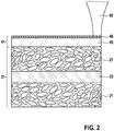
- Figure 2 shows a sectional view at an anode foil 31 and a first separator foil 41 while welding by dint of a laser beam 80.
- a laser source 82 that is not shown here emits the laser beam 80. Thereat, the laser beam 80 is directed to the first separator foil 41.
- the wavelength of the laser beam 80 is about 0,5 - 2 ⁇ m, in particular 0,9 - 1,07 ⁇ m.
- the power of the laser beam 80 is about 1 - 20000 W, in particular 10 - 4000 W, especially 100 - 500 W.
- the anode foil 31 comprises an anode current collector 23 that is sandwiched between two anode layers which contain the anode composite material 21.
- the anode current collector 23 is electrically conductive and is made of copper.
- the thickness of the anode current collector 23 is about 9 - 12 ⁇ m.
- the anode composite material 21 is porous and contains graphite particles as anode active material, a conductive agent and a binder.
- the thickness of the anode foil 31 is about 20 - 1000 ⁇ m, in particular 50 - 300 ⁇ m.
- the first separator foil 41 contains a polymer layer 45 that is placed facing the anode foil 31. Thereat, the polymer layer 45 is placed adjacent to and in direct contact with the anode composite material 21. The thickness of the polymer layer 45 is about 9 - 16 ⁇ m.
- the first separator foil 41 also contains a ceramic layer 46 that is placed averted from the anode foil 31. The thickness of the ceramic layer 46 is about 1 - 5 ⁇ m.
- Figure 3 shows an augmented view from figure 2 .
- the laser beam 80 propagates into a propagation direction z which is oriented orthogonal to the surface of the first separator foil 41.
- the laser beam 80 is directed onto the first separator foil 41 such that energy of the laser beam 80 largely penetrates the first separator foil 41 and that the anode composite material 21 of the anode foil 31 largely absorbs the energy of the laser beam 80.
- the polymer layer 45 and the ceramic layer 46 are transparent for the laser beam 80.
- a direction orthogonal to the propagation direction z is called radial direction r.
- the laser beam 80 has a varying diameter d.
- the diameter d of the laser beam 80 is about 1 to 3000 ⁇ m, in particular 300 - 600 ⁇ m.
- an isophote l1 is shown.
- the extension b1 in radial direction r of said isophote l1 is smaller than the diameter d of the laser beam 80.
- the isophote l1 shown here holds, for example, an energy content of about 63% of the energy of the laser beam 80. Also, welding by using the process window within other isophotes is possible, for example with an energy content of 87% of the Gaussian laser beam intensity distribution.
- the temperature of the anode composite material 21 is rising.
- the energy of the laser beam 80 is applied such that the anode composite material 21 is heated to a temperature below a melting point or below a decomposition temperature of the anode composite material 21 and above or near to a melting point or a softening point of the polymer layer 45 of the first separator foil 41. Thereat, heat is transferred from the anode composite material 21 towards the polymer layer 45 of the first separator foil 41.
- the polymer layer 45 of the first separator foil 41 is melting or softening partly and material of the polymer layer 45 is flowing into or adapted to micro pores of the anode composite material 21.
- the material of the polymer layer 45 is solidified.
- the first separator foil 41 is welded to the anode foil 31.
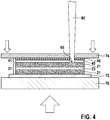
- FIG 4 shows a schematic view at a welding process according to a first embodiment.
- the anode foil 31 is placed on a steel plate 72 which is placed on a table 70, for example a lifting table. Other plate materials are also possible.
- a glass pane 74 is pressed onto the first separator foil 41 and towards the table 70 as indicated by arrows.
- the glass pane 74 is transparent for the laser beam 80.
- the first separator foil 41 is pressed against the anode foil 31 by dint of the glass pane 74 while the first separator foil 41 is welded to the anode foil 31.
- the laser beam 80 penetrates the first separator foil 41 and the glass pane 74.
- the energy of the laser beam 80 generates a welding area 65 in a border zone of the anode composite material 21.
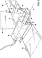
- FIG. 5 shows a schematic view at a welding process according to a second embodiment.
- the first separator foil 41 is fed as a long tape.
- the anode foil 31 is pre-cut into single anode elements 35 that are placed on a transport belt 98.
- the first separator foil 41 is placed on the anode elements 35 by dint of a roller 96.
- Anode taps 25 protrude from the anode current collectors 23 of the anode elements 35.
- the first separator foil 41 is pressed against the anode elements 35 by dint of a tubular member 90.
- the tubular member 90 is transparent for the laser beam 80 and rotationally symmetric to a central axis 94. During welding operation, the tubular member 90 rotates about the central axis 94.
- a laser source 82 that emits the laser beam 80 is placed inside the tubular member 90.
- the laser source 82 is arranged such that the laser beam 80 is directed to an edge area of the first separator foil 41.
- Another laser source 82, that is not visible here, is arranged inside the tubular member 90 such that the laser beam 80 emitted by said laser source 82 is directed to an opposite edge area of the first separator foil 41. Both laser beams 80 generate welding areas 65 on opposite edge areas of the first separator foil 41.
- FIG. 6 shows a sectional view at an electrode tape 50.
- the electrode tape 50 comprises the first separator foil 41 which is welded to the anode foil 31 as described above.
- the electrode tape 50 further comprises a cathode foil 32 which comprises a cathode current collector 24 that is sandwiched between two cathode layers which contain a cathode composite material 22.
- the cathode current collector 24 is electrically conductive and is made of aluminium.
- the electrode tape 50 also comprises a second separator foil 42 that contains a polymer layer 45 and a ceramic layer 46.
- the cathode foil 32 is placed on the first separator foil 41.
- An adhesive compound 60 is applied on edge areas of the first separator foil 41.
- the second separator foil 42 is then placed on the cathode foil 32.
- the second separator foil 42 is joined to the first separator foil 41 by dint of said adhesive compound 60.
- the adhesive compound 60 can be glue or any other material having adhesive properties. Alternatively, also any other joining technique can be used.
- the second separator foil 42 is placed such that the ceramic layer 46 faces the cathode foil 32.
- the first separator foil 41 is placed such that the ceramic layer 46 faces the cathode foil 32.
- the cathode composite material 22 is in direct contact with the ceramic layers 46 of the separator foils 41, 42.
- the width of the welding areas 65 is about 500 ⁇ m.
- the electrode tape 50 is then cut to electrode sub-stacks 52.
- a semi transparent view at an electrode sub-stack 52 is given in figure 7 .
- An anode tap 25 protrudes from the anode current collector 23.
- a cathode tap 26 protrudes from the cathode current collector 24.
- the anode tap 25 and the cathode tap 26 protrude into the same direction.
- a plurality of electrode sub-stacks 52 are placed on top of each other as to form an electrode assembly 10 shaped as an electrode stack.
- the anode taps 25 protruding from the anode current collectors 23 are connected electrically with each other.
- the cathode taps 26 protruding from the cathode current collectors 24 are also connected electrically with each other.
Landscapes
- Chemical & Material Sciences (AREA)
- Chemical Kinetics & Catalysis (AREA)
- Electrochemistry (AREA)
- General Chemical & Material Sciences (AREA)
- Engineering & Computer Science (AREA)
- Materials Engineering (AREA)
- Manufacturing & Machinery (AREA)
- Inorganic Chemistry (AREA)
- Secondary Cells (AREA)
- Battery Electrode And Active Subsutance (AREA)
- Cell Separators (AREA)
Abstract
Description
- The invention relates to a method for producing an electrode assembly for a battery cell, in particular for a lithium ion battery cell, comprising an anode foil, a first separator foil, a cathode foil and a second separator foil. The invention also relates to a battery cell that comprises at least one electrode assembly according to the invention.
- Electrical energy can be stored by means of batteries. Batteries change chemical energy into electrical energy. Particularly, rechargeable batteries are known that can be charged and discharged several times. Batteries or battery modules comprise several battery cells that are connected electrically in series or in parallel.
- Especially, lithium ion battery cells are used in rechargeable batteries or battery systems. Lithium ion battery cells have a relatively high energy density. Lithium ion battery cells are used for instance in motor vehicles, in particular in electric vehicles (EV), in hybrid electric vehicles (HEV) and in plug-in hybrid vehicles (PHEV). Lithium ion battery cells may comprise one or more electrode assemblies.
- Electrode assemblies have a positive electrode called cathode and a negative electrode called anode. The anode and the cathode are separated from one another by means of a separator. The electrodes of the battery cell can be formed like foils and wound with interposition of the separator to form an electrode roll, also referred to as jelly-roll. Alternatively, the electrodes can be layered with interposition of the separator to form an electrode stack. The foils of the anode, the cathode and the separator are joined for example by lamination techniques using rolling.
- The electrodes and the separator are impregnated by an electrolyte that is normally in liquid state, gel state or in solid state. The electrodes of the electrode assemblies are connected to the terminals of the battery cell. The battery cell can be charged and discharged via the terminals.
- Both, the cathode and the anode, comprise a current collector on which a composite material containing an active material, a binder and/or a conductive agent, e.g. carbon black, is applied. The current collector of the cathode is typically made of aluminium and the current collector of the anode is typically made of copper. The cathode composite material contains, for example, a metal oxide as active material. The anode composite material contains, for example, graphite or silicon as active material. In the active material of the anode lithium ions are intercalated.
- In a charging process of the battery cell, lithium ions are migrating from the cathode to the anode through the separator while simultaneously electrons flow in an external circuit from the cathode to the anode. In a discharge process, the lithium ions move within the battery cell from the anode to the cathode and electrons flow in the external circuit from the anode to the cathode.
-
Document DE 10 2009 022 678 A1 discloses an electrode assembly with a separator. The separator is formed as a composite material containing ceramic and polymer materials. In particular, the separator comprises a base layer formed of an organic material coated with an inorganic material. The electrode assembly is shaped as a jelly roll. - Document
US 2014/248541 A1 discloses a solid electrolyte for a lithium battery comprising at least one zone made of lithiated glass-ceramic material. Thereat, a part of a lithiated ceramic material is irradiated by a laser beam in order to achieve melting of the lithiated ceramic material and to obtain a vitreous phase after solidification. - A method for producing an electrode assembly for a battery cell is proposed. Thereat, an anode foil is provided and a first separator foil is placed on the anode foil. The first separator foil then is welded to the anode foil by dint of a laser beam. A cathode foil is placed on the first separator foil and a second separator foil is placed on the cathode foil.
- Thereat, the anode foil comprises an anode current collector that is sandwiched between two anode layers which contain an anode composite material. The anode current collector is electrically conductive and is made of a metal, in particular of copper. The cathode foil comprises a cathode current collector that is sandwiched between two cathode layers which contain a cathode composite material. The cathode current collector is electrically conductive and is made of a metal, in particular of aluminium.
- According to an advantageous embodiment of the invention, the laser beam is directed onto the first separator foil such that energy of the laser beam largely penetrates the first separator foil and such that the anode composite material of the anode foil largely absorbs the energy of the laser beam. By absorbing said energy of the laser beam, the temperature of the anode composite material is rising.
- Preferably, the anode composite material contains graphite as anode active material. Thereat, the anode composite material may contain further materials, for example a conductive agent and a binder.
- According to an advantageous development of the invention, the first separator foil contains a polymer layer that is placed facing the anode foil. Hence, the polymer layer of the first separator foil is placed adjacent to and in direct contact with the anode composite material.
- According to a preferred embodiment of the invention, the energy of the laser beam is applied such that the anode composite material is heated to a temperature below a melting point or below a decomposition temperature of the anode composite material and above or near to a melting point or a softening point of the polymer layer of the first separator foil. In particular, the anode composite material is heated to a temperature below a melting point or below a decomposition temperature of the anode active material.
- Hence, heat is transferred from the anode composite material towards the polymer layer of the first separator foil. Thereupon, the polymer layer of the first separator foil is melting or softening partly and material of the polymer layer is flowing into or adapted or to micro pores of the anode composite material. When the anode composite material and the polymer layer are cooling down, the material of the polymer layer is solidified and hence, the first separator foil is joined to the anode foil by welding.
- Advantageously, the first separator foil contains a ceramic layer that is placed averted from the anode foil. Hence, the ceramic layer of the first separator foil is placed facing the cathode foil.
- According to an advantageous embodiment of the invention, the first separator foil is pressed against the anode foil while the first separator foil is welded to the anode foil by dint of the laser beam. In particular, the first separator foil is pressed against the anode foil by dint of a glass pane that is transparent for the laser beam. Hence, the laser beam also penetrates said glass pane while welding the first separator foil to the anode foil.
- According to a preferred development of the invention, the first separator foil is pressed against the anode foil by dint of a tubular member that is made of a transparent material. In particular, said material of the tubular member is transparent for the laser beam. Preferably, the tubular member is rotationally symmetric to a central axis.
- Preferable, at least one laser source that emits the laser beam is placed inside the tubular member.
- Further preferably, the tubular member rotates about the central axis to which the tubular member is rotationally symmetric.
- According to a preferred development of the invention, the second separator foil is joined to the cathode foil and/or to the first separator foil, in particular, after the first separator foil has been welded to the first anode foil. The second separator foil is preferably designed like the first separator foil and hence contains a polymer layer and a ceramic layer. Thereat, the second separator foil is arranged such that the ceramic layer of the second separator foil is facing the cathode composite material of the cathode foil.
- Preferably, the second separator foil is joined to the cathode foil and/or to the first separator foil by dint of an adhesive compound. The adhesive compound can be glue or any possible other material able to form a join via two ceramic coated separators. But any other joining techniques are also feasible.
- Advantageously, the anode foil, the first separator foil, the cathode foil and the second separator foil are merged as to form an electrode tape. Thereat, said the electrode tape is cut to electrode sub-stacks.
- Afterwards, a plurality of electrode sub-stacks are placed on top of each other as to form an electrode assembly shaped as an electrode stack. Furthermore, anode taps protruding from the anode current collectors are connected electrically and cathode taps protruding from the cathode current collectors are connected electrically.
- Also, a battery cell is proposed that comprises at least one electrode assembly which is produced using the method according to the invention.
- A battery cell according to the invention is usable advantageously in particular in an electric vehicle (EV), in a hybrid electric vehicle (HEV), in a plug-in hybrid vehicle (PH EV), in a stationary battery or in a battery in a marine application. But also other applications are feasible.
- The method for producing an electrode assembly according to the invention allows joining the anode foil to the separator foil easily and quickly without adding additional material. Hence, lithium ion diffusion rate is raised compared to electrode assemblies in which an anode foil is fixed, for example by gluing, needling, sewing or welding to a separator foil. Dissolution of additional glue material into the electrolyte may impact onto long-term cycling performance of the battery cell. Furthermore, mechanically fixed electrode sub-stacks are produced that can be stacked to form an electrode assembly as an electrode stack. In particular, upside down alignment and transportation of the electrode sub-stacks is possible. It is sufficient to weld the separator foil to the anode foil in edge areas of the later electrode sub-stacks. It is not necessary to weld the separator foil to the anode foil large-scaled over their whole surface. In particular, when using a tubular member rotating about a central axis for pressing the separator foil against the anode foil, the method according to the invention can be executed continuously and quickly.
- For a better understanding of the aforementioned embodiments of the invention as well as additional embodiments thereof, reference should be made to the description of embodiments below, in conjunction with the appended drawings showing:
- Figure 1
- a schematic view at a battery cell,
- Figure 2
- a sectional view at a an anode foil and a separator foil while welding,
- Figure 3
- an augmented view from
figure 2 , - Figure 4
- a schematic view at a welding process according to a first embodiment,
- Figure 5
- a schematic view at a welding process according to a second embodiment,
- Figure 6
- a sectional view at a an electrode tape and
- Figure 7
- a semi transparent view at an electrode sub-stack.
- Hereinafter, preferred embodiments of the present invention will be described with reference to the drawings. The drawings only provide schematic views of the invention. Like reference numerals refer to corresponding parts, elements or components throughout the figures, unless indicated otherwise.
-
Figure 1 shows a schematic view at a battery cell 2. The battery cell 2 contains ahousing 3 which is for example of pouch type and which has a prismatic shape. The battery cell 2 further contains anelectrode assembly 10, which is arranged within thehousing 3. Thehousing 3 is a bag or a pouch made of a soft material that surrounds theelectrode assembly 10. - Furthermore, the battery cell 2 contains a
negative terminal 15 and apositive terminal 16. Theterminals terminals housing 3. - The
electrode assembly 10 contains ananode 11, acathode 12 and aseparator 18 that is arranged between theanode 11 and thecathode 12. Presently, theelectrode assembly 10 is shaped as an electrode stack. That means theanode 11 and thecathode 12 of theelectrode assembly 10 consist of several flat sheets that are stacked alternately to form a pile or a stack. Theseparator 18 also consists of several flat sheets that are stacked between the sheets of theanode 11 and the sheets of thecathode 12. - The
anode 11 contains ananode composite material 21 and an anodecurrent collector 23. Theanode composite material 21 and the anodecurrent collector 23 are attached to one another. The anodecurrent collector 23 is electrically conductive and is made of a metal, in particular of copper. The anodecurrent collector 23 is electrically connected to thenegative terminal 15 of the battery cell 2. Theanode composite material 21 presently contains graphite as active material. - The
cathode 12 contains acathode composite material 22 and a cathodecurrent collector 24. Thecathode composite material 22 and the cathodecurrent collector 24 are attached to one another. The cathodecurrent collector 24 is electrically conductive and is made of a metal, in particular of aluminium. The cathodecurrent collector 24 is electrically connected to thepositive terminal 16 of the battery cell 2. Thecathode composite material 22 presently contains metal oxide as active material. -
Figure 2 shows a sectional view at ananode foil 31 and afirst separator foil 41 while welding by dint of alaser beam 80. Alaser source 82 that is not shown here emits thelaser beam 80. Thereat, thelaser beam 80 is directed to thefirst separator foil 41. The wavelength of thelaser beam 80 is about 0,5 - 2 µm, in particular 0,9 - 1,07 µm. The power of thelaser beam 80 is about 1 - 20000 W, in particular 10 - 4000 W, especially 100 - 500 W. - The
anode foil 31 comprises an anodecurrent collector 23 that is sandwiched between two anode layers which contain theanode composite material 21. The anodecurrent collector 23 is electrically conductive and is made of copper. The thickness of the anodecurrent collector 23 is about 9 - 12 µm. Theanode composite material 21 is porous and contains graphite particles as anode active material, a conductive agent and a binder. The thickness of theanode foil 31 is about 20 - 1000 µm, in particular 50 - 300 µm. - The
first separator foil 41 contains apolymer layer 45 that is placed facing theanode foil 31. Thereat, thepolymer layer 45 is placed adjacent to and in direct contact with theanode composite material 21. The thickness of thepolymer layer 45 is about 9 - 16 µm. Thefirst separator foil 41 also contains aceramic layer 46 that is placed averted from theanode foil 31. The thickness of theceramic layer 46 is about 1 - 5 µm. -
Figure 3 shows an augmented view fromfigure 2 . Thelaser beam 80 propagates into a propagation direction z which is oriented orthogonal to the surface of thefirst separator foil 41. Thelaser beam 80 is directed onto thefirst separator foil 41 such that energy of thelaser beam 80 largely penetrates thefirst separator foil 41 and that theanode composite material 21 of theanode foil 31 largely absorbs the energy of thelaser beam 80. Thepolymer layer 45 and theceramic layer 46 are transparent for thelaser beam 80. - A direction orthogonal to the propagation direction z is called radial direction r. In said radial direction r, the
laser beam 80 has a varying diameter d. Close to the surface of thefirst separator foil 41 the diameter d of thelaser beam 80 is about 1 to 3000 µm, in particular 300 - 600 µm. - In
figure 3 , an isophote l1 is shown. The extension b1 in radial direction r of said isophote l1 is smaller than the diameter d of thelaser beam 80. The isophote l1 shown here holds, for example, an energy content of about 63% of the energy of thelaser beam 80. Also, welding by using the process window within other isophotes is possible, for example with an energy content of 87% of the Gaussian laser beam intensity distribution. - By absorbing the energy of the
laser beam 80, the temperature of theanode composite material 21 is rising. The energy of thelaser beam 80 is applied such that theanode composite material 21 is heated to a temperature below a melting point or below a decomposition temperature of theanode composite material 21 and above or near to a melting point or a softening point of thepolymer layer 45 of thefirst separator foil 41. Thereat, heat is transferred from theanode composite material 21 towards thepolymer layer 45 of thefirst separator foil 41. - Thereupon, the
polymer layer 45 of thefirst separator foil 41 is melting or softening partly and material of thepolymer layer 45 is flowing into or adapted to micro pores of theanode composite material 21. When theanode composite material 21 and thepolymer layer 45 are cooled down, the material of thepolymer layer 45 is solidified. Hence, thefirst separator foil 41 is welded to theanode foil 31. -
Figure 4 shows a schematic view at a welding process according to a first embodiment. Theanode foil 31 is placed on asteel plate 72 which is placed on a table 70, for example a lifting table. Other plate materials are also possible. Aglass pane 74 is pressed onto thefirst separator foil 41 and towards the table 70 as indicated by arrows. Theglass pane 74 is transparent for thelaser beam 80. - Hence, the
first separator foil 41 is pressed against theanode foil 31 by dint of theglass pane 74 while thefirst separator foil 41 is welded to theanode foil 31. Thereat, thelaser beam 80 penetrates thefirst separator foil 41 and theglass pane 74. The energy of thelaser beam 80 generates awelding area 65 in a border zone of theanode composite material 21. -
Figure 5 shows a schematic view at a welding process according to a second embodiment. Thefirst separator foil 41 is fed as a long tape. Theanode foil 31 is pre-cut intosingle anode elements 35 that are placed on atransport belt 98. Thefirst separator foil 41 is placed on theanode elements 35 by dint of aroller 96. Anode taps 25 protrude from the anodecurrent collectors 23 of theanode elements 35. - The
first separator foil 41 is pressed against theanode elements 35 by dint of atubular member 90. Thetubular member 90 is transparent for thelaser beam 80 and rotationally symmetric to acentral axis 94. During welding operation, thetubular member 90 rotates about thecentral axis 94. - A
laser source 82 that emits thelaser beam 80 is placed inside thetubular member 90. Thelaser source 82 is arranged such that thelaser beam 80 is directed to an edge area of thefirst separator foil 41. Anotherlaser source 82, that is not visible here, is arranged inside thetubular member 90 such that thelaser beam 80 emitted by saidlaser source 82 is directed to an opposite edge area of thefirst separator foil 41. Bothlaser beams 80 generatewelding areas 65 on opposite edge areas of thefirst separator foil 41. -
Figure 6 shows a sectional view at anelectrode tape 50. Theelectrode tape 50 comprises thefirst separator foil 41 which is welded to theanode foil 31 as described above. Theelectrode tape 50 further comprises acathode foil 32 which comprises a cathodecurrent collector 24 that is sandwiched between two cathode layers which contain acathode composite material 22. The cathodecurrent collector 24 is electrically conductive and is made of aluminium. Theelectrode tape 50 also comprises asecond separator foil 42 that contains apolymer layer 45 and aceramic layer 46. - After the
first separator foil 41 is welded to theanode foil 31 by dint of thelaser beam 80, thecathode foil 32 is placed on thefirst separator foil 41. Anadhesive compound 60 is applied on edge areas of thefirst separator foil 41. Thesecond separator foil 42 is then placed on thecathode foil 32. Hence, thesecond separator foil 42 is joined to thefirst separator foil 41 by dint of saidadhesive compound 60. Thus, thecathode foil 32 is fastened between the separator foils 41, 42. Theadhesive compound 60 can be glue or any other material having adhesive properties. Alternatively, also any other joining technique can be used. - The
second separator foil 42 is placed such that theceramic layer 46 faces thecathode foil 32. Also thefirst separator foil 41 is placed such that theceramic layer 46 faces thecathode foil 32. Hence, thecathode composite material 22 is in direct contact with theceramic layers 46 of the separator foils 41, 42. The width of thewelding areas 65 is about 500 µm. - The
electrode tape 50 is then cut toelectrode sub-stacks 52. A semi transparent view at anelectrode sub-stack 52 is given infigure 7 . Ananode tap 25 protrudes from the anodecurrent collector 23. Acathode tap 26 protrudes from the cathodecurrent collector 24. Theanode tap 25 and thecathode tap 26 protrude into the same direction. - Afterwards, a plurality of
electrode sub-stacks 52 are placed on top of each other as to form anelectrode assembly 10 shaped as an electrode stack. The anode taps 25 protruding from the anodecurrent collectors 23 are connected electrically with each other. The cathode taps 26 protruding from the cathodecurrent collectors 24 are also connected electrically with each other. When theelectrode assembly 10 is inserted into the battery cell 2, the anode taps 25 are connected to thenegative terminal 15 and the cathode taps 26 are connected to thepositive terminal 16. - The foregoing description, for purpose of explanation, has been described with reference to specific embodiments. However, the illustrative discussions above are not intended to be exhaustive or to limit the invention to the precise forms disclosed. Many modifications and variations are possible in view of the above teachings and those encompassed by the attached claims. The embodiments were chosen and described in order to explain the principles of the invention and its practical applications, to thereby enable others skilled in the art to utilize the invention and various embodiments with various modifications as are suited to the particular use contemplated.
Claims (15)
- Method for producing an electrode assembly (10) for a battery cell (2), whereat an anode foil (31) is provided,
a first separator foil (41) is placed on the anode foil (31),
the first separator foil (41) is welded to the anode foil (31) by dint of a laser beam (80),
a cathode foil (32) is placed on the first separator foil (41) and
a second separator foil (42) is placed on the cathode foil (32). - Method according to claim 1, whereat
the laser beam (80) is directed onto the first separator foil (41)
such that energy of the laser beam (80) largely penetrates the first separator foil (41) and
such that an anode composite material (21) of the anode foil (31) largely absorbs the energy of the laser beam (80). - Method according to claim 2, whereat
the anode composite material (21) contains graphite. - Method according to one of claims 2 to 3, whereat
the first separator foil (41) contains a polymer layer (45) that is placed facing the anode foil (31). - Method according to claim 4, whereat
the energy of the laser beam (80) is applied such that
the anode composite material (21) is heated to a temperature below a melting point or below a decomposition temperature of the anode composite material (21) and
above or near to a melting point or a softening point of the polymer layer (45). - Method according to one of the preceding claims, whereat
the first separator foil (41) contains a ceramic layer (46) that is placed averted from the anode foil (31). - Method according to one of the preceding claims, whereat
the first separator foil (41) is pressed against the anode foil (31) while
the first separator foil (41) is welded to the anode foil (31) by dint of the laser beam (80). - Method according to claim 7, whereat
the first separator foil (41) is pressed against the anode foil (31) by dint of a tubular member (90) that is made of a transparent material. - Method according to claim 8, whereat
at least one laser source (82) that emits the laser beam (80) is placed inside the tubular member (90). - Method according to one of claims 8 to 9, whereat tubular member (90) rotates about a central axis (94).
- Method according to one of the preceding claims, whereat
the second separator foil (42) is joined to the cathode foil (32) and/or to
the first separator foil (41). - Method according to one of the preceding claims, whereat
the anode foil (31), the first separator foil (41), the cathode foil (32) and
the second separator foil (42) are merged as to form an electrode tape (50) and whereat
the electrode tape (50) is cut to electrode sub-stacks (52). - Method according to claim 12, whereat
a plurality of electrode sub-stacks (52) are placed on top of each other as to form an electrode assembly (10) as an electrode stack. - Battery cell (2), comprising at least one electrode assembly (10) produced using the method according to one of the preceding claims.
- Usage of a battery cell (2) according to claim 14 in an electric vehicle (EV), in a hybrid electric vehicle (HEV), in a plug-in hybrid vehicle (PHEV), in a stationary battery or in a battery in a marine application.
Priority Applications (5)
| Application Number | Priority Date | Filing Date | Title |
|---|---|---|---|
| EP17170039.6A EP3401978B1 (en) | 2017-05-09 | 2017-05-09 | Method for producing an electrode assembly for a battery cell |
| JP2019561973A JP2020520058A (en) | 2017-05-09 | 2018-03-16 | Method of manufacturing electrode assembly for battery cell and battery cell |
| CN201880030407.5A CN110679006B (en) | 2017-05-09 | 2018-03-16 | Method and battery cell for manufacturing electrode assembly for battery cell |
| KR1020197033188A KR20200004811A (en) | 2017-05-09 | 2018-03-16 | Manufacturing method of electrode assembly for battery cell and battery cell |
| PCT/EP2018/056677 WO2018206186A1 (en) | 2017-05-09 | 2018-03-16 | Method for producing an electrode assembly for a battery cell and battery cell |
Applications Claiming Priority (1)
| Application Number | Priority Date | Filing Date | Title |
|---|---|---|---|
| EP17170039.6A EP3401978B1 (en) | 2017-05-09 | 2017-05-09 | Method for producing an electrode assembly for a battery cell |
Publications (2)
| Publication Number | Publication Date |
|---|---|
| EP3401978A1 true EP3401978A1 (en) | 2018-11-14 |
| EP3401978B1 EP3401978B1 (en) | 2022-06-08 |
Family
ID=58692426
Family Applications (1)
| Application Number | Title | Priority Date | Filing Date |
|---|---|---|---|
| EP17170039.6A Active EP3401978B1 (en) | 2017-05-09 | 2017-05-09 | Method for producing an electrode assembly for a battery cell |
Country Status (5)
| Country | Link |
|---|---|
| EP (1) | EP3401978B1 (en) |
| JP (1) | JP2020520058A (en) |
| KR (1) | KR20200004811A (en) |
| CN (1) | CN110679006B (en) |
| WO (1) | WO2018206186A1 (en) |
Cited By (1)
| Publication number | Priority date | Publication date | Assignee | Title |
|---|---|---|---|---|
| GB2639035A (en) * | 2024-03-08 | 2025-09-10 | Mercedes Benz Group Ag | A battery cell for an electrical storage device of an at least in part electrically operated motor vehicle, as well as a method for producing a battery cell |
Families Citing this family (1)
| Publication number | Priority date | Publication date | Assignee | Title |
|---|---|---|---|---|
| CN112968221A (en) * | 2021-01-16 | 2021-06-15 | 珠海冠宇电池股份有限公司 | High-safety lithium ion battery cell, battery and manufacturing method of battery cell |
Citations (7)
| Publication number | Priority date | Publication date | Assignee | Title |
|---|---|---|---|---|
| DE102009022678A1 (en) | 2009-05-26 | 2010-12-02 | Li-Tec Battery Gmbh | electrode winding |
| JP2013178951A (en) * | 2012-02-28 | 2013-09-09 | Nagano Automation Kk | Device for holding polar plate with separator |
| WO2013160932A1 (en) * | 2012-04-23 | 2013-10-31 | オー・エム・シー株式会社 | Method for joining collector of electronic component and device for same |
| US20140248541A1 (en) | 2011-06-16 | 2014-09-04 | Commissariat A L'energie Atomique Et Aux Energies Alternatives | Solid electrolyte for lithium battery, comprising at least one zone of lithium-containing glass ceramic material and method of production |
| WO2015022226A1 (en) * | 2013-08-15 | 2015-02-19 | Robert Bosch Gmbh | Thermal fixing of stacked or folded electrochemical energy storage means |
| JP2016038995A (en) * | 2014-08-06 | 2016-03-22 | 株式会社豊田自動織機 | Power storage device and method for manufacturing power storage device |
| WO2016136550A1 (en) * | 2015-02-26 | 2016-09-01 | 株式会社豊田自動織機 | Electrode unit and method for producing electrode unit |
Family Cites Families (7)
| Publication number | Priority date | Publication date | Assignee | Title |
|---|---|---|---|---|
| JP3355948B2 (en) * | 1996-08-12 | 2002-12-09 | 新神戸電機株式会社 | Prismatic secondary battery and method of manufacturing the same |
| DE102010055402A1 (en) * | 2010-12-21 | 2012-06-21 | Li-Tec Battery Gmbh | Method and system for producing electrical cells for electrochemical energy storage devices |
| CN203503727U (en) * | 2013-05-31 | 2014-03-26 | 深圳市格瑞普电池有限公司 | Positive electrode separator bag and laminated lithium ion battery with the positive electrode separator bag |
| CN103490089A (en) * | 2013-06-17 | 2014-01-01 | 中国科学院物理研究所 | Electrode subassembly, preparation method thereof and lithium secondary battery |
| CN104900905A (en) * | 2015-06-03 | 2015-09-09 | 深圳市迪凯特电池科技有限公司 | Laminated lithium ion battery and production process thereof |
| CN105789678B (en) * | 2016-04-22 | 2018-04-27 | 广东亿鑫丰智能装备股份有限公司 | Cell winding lamination machine is with going up piece device |
| CN105870489B (en) * | 2016-06-07 | 2019-03-01 | 程建聪 | Monomer-polymer lithium ion battery manufacturing method and its assemble method |
-
2017
- 2017-05-09 EP EP17170039.6A patent/EP3401978B1/en active Active
-
2018
- 2018-03-16 WO PCT/EP2018/056677 patent/WO2018206186A1/en not_active Ceased
- 2018-03-16 JP JP2019561973A patent/JP2020520058A/en active Pending
- 2018-03-16 KR KR1020197033188A patent/KR20200004811A/en not_active Withdrawn
- 2018-03-16 CN CN201880030407.5A patent/CN110679006B/en not_active Expired - Fee Related
Patent Citations (7)
| Publication number | Priority date | Publication date | Assignee | Title |
|---|---|---|---|---|
| DE102009022678A1 (en) | 2009-05-26 | 2010-12-02 | Li-Tec Battery Gmbh | electrode winding |
| US20140248541A1 (en) | 2011-06-16 | 2014-09-04 | Commissariat A L'energie Atomique Et Aux Energies Alternatives | Solid electrolyte for lithium battery, comprising at least one zone of lithium-containing glass ceramic material and method of production |
| JP2013178951A (en) * | 2012-02-28 | 2013-09-09 | Nagano Automation Kk | Device for holding polar plate with separator |
| WO2013160932A1 (en) * | 2012-04-23 | 2013-10-31 | オー・エム・シー株式会社 | Method for joining collector of electronic component and device for same |
| WO2015022226A1 (en) * | 2013-08-15 | 2015-02-19 | Robert Bosch Gmbh | Thermal fixing of stacked or folded electrochemical energy storage means |
| JP2016038995A (en) * | 2014-08-06 | 2016-03-22 | 株式会社豊田自動織機 | Power storage device and method for manufacturing power storage device |
| WO2016136550A1 (en) * | 2015-02-26 | 2016-09-01 | 株式会社豊田自動織機 | Electrode unit and method for producing electrode unit |
Non-Patent Citations (1)
| Title |
|---|
| SEIJI KATAYAMA: "Laser joining of metal and plastic - Industrial Laser Solutions", 11 January 2010 (2010-01-11), XP055389422, Retrieved from the Internet <URL:http://www.industrial-lasers.com/articles/print/volume-250/issue-6/features/laser-joining-of-metal-and-plastic.html> [retrieved on 20170710] * |
Cited By (1)
| Publication number | Priority date | Publication date | Assignee | Title |
|---|---|---|---|---|
| GB2639035A (en) * | 2024-03-08 | 2025-09-10 | Mercedes Benz Group Ag | A battery cell for an electrical storage device of an at least in part electrically operated motor vehicle, as well as a method for producing a battery cell |
Also Published As
| Publication number | Publication date |
|---|---|
| KR20200004811A (en) | 2020-01-14 |
| JP2020520058A (en) | 2020-07-02 |
| WO2018206186A1 (en) | 2018-11-15 |
| CN110679006B (en) | 2022-08-12 |
| CN110679006A (en) | 2020-01-10 |
| EP3401978B1 (en) | 2022-06-08 |
Similar Documents
| Publication | Publication Date | Title |
|---|---|---|
| KR101609424B1 (en) | Method of manufacturing electrode assembly | |
| KR101510518B1 (en) | Fabricating method of electrode assembly | |
| KR101543065B1 (en) | Electrode assembly and electrochemical cell containing the same | |
| KR101528027B1 (en) | Fabricating method of electrode assembly | |
| JP6788107B2 (en) | Manufacturing method of electrode unit for battery cell and electrode unit | |
| US9077027B2 (en) | Electrode assembly and secondary battery using the same | |
| KR101523427B1 (en) | Fabricating method of electrode assembly | |
| JP2005276486A (en) | Multilayer battery, battery pack and vehicle | |
| US8703342B2 (en) | Electrode assembly, rechargeable battery including the same, and method of manufacturing an electrode thereof | |
| KR20140012601A (en) | Secondary battery and electrochemical cell having the same | |
| KR101154883B1 (en) | Method for Production of Electrode Assembly with Improved Electrolyte Wetting Property | |
| KR20140022531A (en) | Electrode assembly and fabricating method of electrochemical cell containing the electrode assembly, electrochemical cell | |
| JPH0982305A (en) | Secondary battery and manufacturing method thereof | |
| EP3401978B1 (en) | Method for producing an electrode assembly for a battery cell | |
| US8574756B1 (en) | Prismatic secondary battery | |
| EP4258453A1 (en) | Secondary battery | |
| WO2023210482A1 (en) | Method for producing electrode | |
| KR20120006730A (en) | Secondary Battery Manufacturing Method Using Polymer Electrolyte | |
| KR20090076278A (en) | Secondary Battery with Excellent Sealability | |
| US20250329880A1 (en) | Electrode Assembly And Manufacturing Method Thereof | |
| KR101543076B1 (en) | Electrode assembly and electrochemical cell containing the same | |
| KR102069512B1 (en) | Electrode Assembly Comprising Two-typed Separators | |
| KR102197360B1 (en) | Electrode Assembly Comprising One-sided Coating Electrode of Improved Mechanical Strength | |
| CN114335750A (en) | Non-aqueous electrolyte secondary battery | |
| KR102154014B1 (en) | An electrode for an electrochemical device and an electrochemical device comprising the same |
Legal Events
| Date | Code | Title | Description |
|---|---|---|---|
| PUAI | Public reference made under article 153(3) epc to a published international application that has entered the european phase |
Free format text: ORIGINAL CODE: 0009012 |
|
| STAA | Information on the status of an ep patent application or granted ep patent |
Free format text: STATUS: THE APPLICATION HAS BEEN PUBLISHED |
|
| AK | Designated contracting states |
Kind code of ref document: A1 Designated state(s): AL AT BE BG CH CY CZ DE DK EE ES FI FR GB GR HR HU IE IS IT LI LT LU LV MC MK MT NL NO PL PT RO RS SE SI SK SM TR |
|
| AX | Request for extension of the european patent |
Extension state: BA ME |
|
| STAA | Information on the status of an ep patent application or granted ep patent |
Free format text: STATUS: REQUEST FOR EXAMINATION WAS MADE |
|
| 17P | Request for examination filed |
Effective date: 20190514 |
|
| RBV | Designated contracting states (corrected) |
Designated state(s): AL AT BE BG CH CY CZ DE DK EE ES FI FR GB GR HR HU IE IS IT LI LT LU LV MC MK MT NL NO PL PT RO RS SE SI SK SM TR |
|
| RAP1 | Party data changed (applicant data changed or rights of an application transferred) |
Owner name: GS YUASA INTERNATIONAL LTD. Owner name: ROBERT BOSCH GMBH |
|
| RAP1 | Party data changed (applicant data changed or rights of an application transferred) |
Owner name: ROBERT BOSCH GMBH Owner name: GS YUASA INTERNATIONAL LTD. |
|
| STAA | Information on the status of an ep patent application or granted ep patent |
Free format text: STATUS: EXAMINATION IS IN PROGRESS |
|
| 17Q | First examination report despatched |
Effective date: 20200805 |
|
| RIC1 | Information provided on ipc code assigned before grant |
Ipc: H01M 10/0525 20100101ALN20211025BHEP Ipc: H01M 4/133 20100101ALI20211025BHEP Ipc: H01M 50/46 20210101ALI20211025BHEP Ipc: H01M 50/449 20210101AFI20211025BHEP |
|
| REG | Reference to a national code |
Ref country code: DE Ref legal event code: R079 Ref document number: 602017058224 Country of ref document: DE Free format text: PREVIOUS MAIN CLASS: H01M0002160000 Ipc: H01M0050449000 |
|
| GRAP | Despatch of communication of intention to grant a patent |
Free format text: ORIGINAL CODE: EPIDOSNIGR1 |
|
| STAA | Information on the status of an ep patent application or granted ep patent |
Free format text: STATUS: GRANT OF PATENT IS INTENDED |
|
| RIC1 | Information provided on ipc code assigned before grant |
Ipc: H01M 10/0525 20100101ALN20211216BHEP Ipc: H01M 4/133 20100101ALI20211216BHEP Ipc: H01M 50/46 20210101ALI20211216BHEP Ipc: H01M 50/449 20210101AFI20211216BHEP |
|
| INTG | Intention to grant announced |
Effective date: 20220110 |
|
| GRAS | Grant fee paid |
Free format text: ORIGINAL CODE: EPIDOSNIGR3 |
|
| GRAA | (expected) grant |
Free format text: ORIGINAL CODE: 0009210 |
|
| STAA | Information on the status of an ep patent application or granted ep patent |
Free format text: STATUS: THE PATENT HAS BEEN GRANTED |
|
| AK | Designated contracting states |
Kind code of ref document: B1 Designated state(s): AL AT BE BG CH CY CZ DE DK EE ES FI FR GB GR HR HU IE IS IT LI LT LU LV MC MK MT NL NO PL PT RO RS SE SI SK SM TR |
|
| REG | Reference to a national code |
Ref country code: AT Ref legal event code: REF Ref document number: 1497550 Country of ref document: AT Kind code of ref document: T Effective date: 20220615 Ref country code: CH Ref legal event code: EP |
|
| REG | Reference to a national code |
Ref country code: DE Ref legal event code: R096 Ref document number: 602017058224 Country of ref document: DE |
|
| REG | Reference to a national code |
Ref country code: IE Ref legal event code: FG4D |
|
| REG | Reference to a national code |
Ref country code: LT Ref legal event code: MG9D |
|
| REG | Reference to a national code |
Ref country code: NL Ref legal event code: MP Effective date: 20220608 |
|
| PG25 | Lapsed in a contracting state [announced via postgrant information from national office to epo] |
Ref country code: SE Free format text: LAPSE BECAUSE OF FAILURE TO SUBMIT A TRANSLATION OF THE DESCRIPTION OR TO PAY THE FEE WITHIN THE PRESCRIBED TIME-LIMIT Effective date: 20220608 Ref country code: NO Free format text: LAPSE BECAUSE OF FAILURE TO SUBMIT A TRANSLATION OF THE DESCRIPTION OR TO PAY THE FEE WITHIN THE PRESCRIBED TIME-LIMIT Effective date: 20220908 Ref country code: LT Free format text: LAPSE BECAUSE OF FAILURE TO SUBMIT A TRANSLATION OF THE DESCRIPTION OR TO PAY THE FEE WITHIN THE PRESCRIBED TIME-LIMIT Effective date: 20220608 Ref country code: HR Free format text: LAPSE BECAUSE OF FAILURE TO SUBMIT A TRANSLATION OF THE DESCRIPTION OR TO PAY THE FEE WITHIN THE PRESCRIBED TIME-LIMIT Effective date: 20220608 Ref country code: GR Free format text: LAPSE BECAUSE OF FAILURE TO SUBMIT A TRANSLATION OF THE DESCRIPTION OR TO PAY THE FEE WITHIN THE PRESCRIBED TIME-LIMIT Effective date: 20220909 Ref country code: FI Free format text: LAPSE BECAUSE OF FAILURE TO SUBMIT A TRANSLATION OF THE DESCRIPTION OR TO PAY THE FEE WITHIN THE PRESCRIBED TIME-LIMIT Effective date: 20220608 Ref country code: ES Free format text: LAPSE BECAUSE OF FAILURE TO SUBMIT A TRANSLATION OF THE DESCRIPTION OR TO PAY THE FEE WITHIN THE PRESCRIBED TIME-LIMIT Effective date: 20220608 Ref country code: BG Free format text: LAPSE BECAUSE OF FAILURE TO SUBMIT A TRANSLATION OF THE DESCRIPTION OR TO PAY THE FEE WITHIN THE PRESCRIBED TIME-LIMIT Effective date: 20220908 |
|
| REG | Reference to a national code |
Ref country code: AT Ref legal event code: MK05 Ref document number: 1497550 Country of ref document: AT Kind code of ref document: T Effective date: 20220608 |
|
| PG25 | Lapsed in a contracting state [announced via postgrant information from national office to epo] |
Ref country code: RS Free format text: LAPSE BECAUSE OF FAILURE TO SUBMIT A TRANSLATION OF THE DESCRIPTION OR TO PAY THE FEE WITHIN THE PRESCRIBED TIME-LIMIT Effective date: 20220608 Ref country code: LV Free format text: LAPSE BECAUSE OF FAILURE TO SUBMIT A TRANSLATION OF THE DESCRIPTION OR TO PAY THE FEE WITHIN THE PRESCRIBED TIME-LIMIT Effective date: 20220608 |
|
| PG25 | Lapsed in a contracting state [announced via postgrant information from national office to epo] |
Ref country code: NL Free format text: LAPSE BECAUSE OF FAILURE TO SUBMIT A TRANSLATION OF THE DESCRIPTION OR TO PAY THE FEE WITHIN THE PRESCRIBED TIME-LIMIT Effective date: 20220608 |
|
| PG25 | Lapsed in a contracting state [announced via postgrant information from national office to epo] |
Ref country code: SM Free format text: LAPSE BECAUSE OF FAILURE TO SUBMIT A TRANSLATION OF THE DESCRIPTION OR TO PAY THE FEE WITHIN THE PRESCRIBED TIME-LIMIT Effective date: 20220608 Ref country code: SK Free format text: LAPSE BECAUSE OF FAILURE TO SUBMIT A TRANSLATION OF THE DESCRIPTION OR TO PAY THE FEE WITHIN THE PRESCRIBED TIME-LIMIT Effective date: 20220608 Ref country code: RO Free format text: LAPSE BECAUSE OF FAILURE TO SUBMIT A TRANSLATION OF THE DESCRIPTION OR TO PAY THE FEE WITHIN THE PRESCRIBED TIME-LIMIT Effective date: 20220608 Ref country code: PT Free format text: LAPSE BECAUSE OF FAILURE TO SUBMIT A TRANSLATION OF THE DESCRIPTION OR TO PAY THE FEE WITHIN THE PRESCRIBED TIME-LIMIT Effective date: 20221010 Ref country code: EE Free format text: LAPSE BECAUSE OF FAILURE TO SUBMIT A TRANSLATION OF THE DESCRIPTION OR TO PAY THE FEE WITHIN THE PRESCRIBED TIME-LIMIT Effective date: 20220608 Ref country code: CZ Free format text: LAPSE BECAUSE OF FAILURE TO SUBMIT A TRANSLATION OF THE DESCRIPTION OR TO PAY THE FEE WITHIN THE PRESCRIBED TIME-LIMIT Effective date: 20220608 Ref country code: AT Free format text: LAPSE BECAUSE OF FAILURE TO SUBMIT A TRANSLATION OF THE DESCRIPTION OR TO PAY THE FEE WITHIN THE PRESCRIBED TIME-LIMIT Effective date: 20220608 |
|
| PG25 | Lapsed in a contracting state [announced via postgrant information from national office to epo] |
Ref country code: PL Free format text: LAPSE BECAUSE OF FAILURE TO SUBMIT A TRANSLATION OF THE DESCRIPTION OR TO PAY THE FEE WITHIN THE PRESCRIBED TIME-LIMIT Effective date: 20220608 Ref country code: IS Free format text: LAPSE BECAUSE OF FAILURE TO SUBMIT A TRANSLATION OF THE DESCRIPTION OR TO PAY THE FEE WITHIN THE PRESCRIBED TIME-LIMIT Effective date: 20221008 |
|
| REG | Reference to a national code |
Ref country code: DE Ref legal event code: R097 Ref document number: 602017058224 Country of ref document: DE |
|
| PG25 | Lapsed in a contracting state [announced via postgrant information from national office to epo] |
Ref country code: AL Free format text: LAPSE BECAUSE OF FAILURE TO SUBMIT A TRANSLATION OF THE DESCRIPTION OR TO PAY THE FEE WITHIN THE PRESCRIBED TIME-LIMIT Effective date: 20220608 |
|
| PLBE | No opposition filed within time limit |
Free format text: ORIGINAL CODE: 0009261 |
|
| STAA | Information on the status of an ep patent application or granted ep patent |
Free format text: STATUS: NO OPPOSITION FILED WITHIN TIME LIMIT |
|
| PG25 | Lapsed in a contracting state [announced via postgrant information from national office to epo] |
Ref country code: DK Free format text: LAPSE BECAUSE OF FAILURE TO SUBMIT A TRANSLATION OF THE DESCRIPTION OR TO PAY THE FEE WITHIN THE PRESCRIBED TIME-LIMIT Effective date: 20220608 |
|
| 26N | No opposition filed |
Effective date: 20230310 |
|
| PG25 | Lapsed in a contracting state [announced via postgrant information from national office to epo] |
Ref country code: SI Free format text: LAPSE BECAUSE OF FAILURE TO SUBMIT A TRANSLATION OF THE DESCRIPTION OR TO PAY THE FEE WITHIN THE PRESCRIBED TIME-LIMIT Effective date: 20220608 |
|
| PGFP | Annual fee paid to national office [announced via postgrant information from national office to epo] |
Ref country code: IT Payment date: 20230526 Year of fee payment: 7 Ref country code: FR Payment date: 20230526 Year of fee payment: 7 Ref country code: DE Payment date: 20230531 Year of fee payment: 7 |
|
| REG | Reference to a national code |
Ref country code: CH Ref legal event code: PL |
|
| PG25 | Lapsed in a contracting state [announced via postgrant information from national office to epo] |
Ref country code: MC Free format text: LAPSE BECAUSE OF FAILURE TO SUBMIT A TRANSLATION OF THE DESCRIPTION OR TO PAY THE FEE WITHIN THE PRESCRIBED TIME-LIMIT Effective date: 20220608 |
|
| GBPC | Gb: european patent ceased through non-payment of renewal fee |
Effective date: 20230509 |
|
| REG | Reference to a national code |
Ref country code: BE Ref legal event code: MM Effective date: 20230531 |
|
| PG25 | Lapsed in a contracting state [announced via postgrant information from national office to epo] |
Ref country code: MC Free format text: LAPSE BECAUSE OF FAILURE TO SUBMIT A TRANSLATION OF THE DESCRIPTION OR TO PAY THE FEE WITHIN THE PRESCRIBED TIME-LIMIT Effective date: 20220608 Ref country code: LU Free format text: LAPSE BECAUSE OF NON-PAYMENT OF DUE FEES Effective date: 20230509 Ref country code: LI Free format text: LAPSE BECAUSE OF NON-PAYMENT OF DUE FEES Effective date: 20230531 Ref country code: CH Free format text: LAPSE BECAUSE OF NON-PAYMENT OF DUE FEES Effective date: 20230531 |
|
| REG | Reference to a national code |
Ref country code: IE Ref legal event code: MM4A |
|
| PG25 | Lapsed in a contracting state [announced via postgrant information from national office to epo] |
Ref country code: IE Free format text: LAPSE BECAUSE OF NON-PAYMENT OF DUE FEES Effective date: 20230509 |
|
| PG25 | Lapsed in a contracting state [announced via postgrant information from national office to epo] |
Ref country code: IE Free format text: LAPSE BECAUSE OF NON-PAYMENT OF DUE FEES Effective date: 20230509 Ref country code: GB Free format text: LAPSE BECAUSE OF NON-PAYMENT OF DUE FEES Effective date: 20230509 |
|
| PG25 | Lapsed in a contracting state [announced via postgrant information from national office to epo] |
Ref country code: BE Free format text: LAPSE BECAUSE OF NON-PAYMENT OF DUE FEES Effective date: 20230531 |
|
| PG25 | Lapsed in a contracting state [announced via postgrant information from national office to epo] |
Ref country code: BG Free format text: LAPSE BECAUSE OF FAILURE TO SUBMIT A TRANSLATION OF THE DESCRIPTION OR TO PAY THE FEE WITHIN THE PRESCRIBED TIME-LIMIT Effective date: 20220608 |
|
| PG25 | Lapsed in a contracting state [announced via postgrant information from national office to epo] |
Ref country code: BG Free format text: LAPSE BECAUSE OF FAILURE TO SUBMIT A TRANSLATION OF THE DESCRIPTION OR TO PAY THE FEE WITHIN THE PRESCRIBED TIME-LIMIT Effective date: 20220608 |
|
| REG | Reference to a national code |
Ref country code: DE Ref legal event code: R119 Ref document number: 602017058224 Country of ref document: DE |
|
| PG25 | Lapsed in a contracting state [announced via postgrant information from national office to epo] |
Ref country code: DE Free format text: LAPSE BECAUSE OF NON-PAYMENT OF DUE FEES Effective date: 20241203 |
|
| PG25 | Lapsed in a contracting state [announced via postgrant information from national office to epo] |
Ref country code: FR Free format text: LAPSE BECAUSE OF NON-PAYMENT OF DUE FEES Effective date: 20240531 |
|
| PG25 | Lapsed in a contracting state [announced via postgrant information from national office to epo] |
Ref country code: IT Free format text: LAPSE BECAUSE OF NON-PAYMENT OF DUE FEES Effective date: 20240509 |
|
| PG25 | Lapsed in a contracting state [announced via postgrant information from national office to epo] |
Ref country code: CY Free format text: LAPSE BECAUSE OF FAILURE TO SUBMIT A TRANSLATION OF THE DESCRIPTION OR TO PAY THE FEE WITHIN THE PRESCRIBED TIME-LIMIT; INVALID AB INITIO Effective date: 20170509 |
|
| PG25 | Lapsed in a contracting state [announced via postgrant information from national office to epo] |
Ref country code: HU Free format text: LAPSE BECAUSE OF FAILURE TO SUBMIT A TRANSLATION OF THE DESCRIPTION OR TO PAY THE FEE WITHIN THE PRESCRIBED TIME-LIMIT; INVALID AB INITIO Effective date: 20170509 |
|
| PG25 | Lapsed in a contracting state [announced via postgrant information from national office to epo] |
Ref country code: TR Free format text: LAPSE BECAUSE OF FAILURE TO SUBMIT A TRANSLATION OF THE DESCRIPTION OR TO PAY THE FEE WITHIN THE PRESCRIBED TIME-LIMIT Effective date: 20220608 |