EP3401534A1 - Valve having a throttle flap arranged in a throttle flap connector - Google Patents
Valve having a throttle flap arranged in a throttle flap connector Download PDFInfo
- Publication number
- EP3401534A1 EP3401534A1 EP17465521.7A EP17465521A EP3401534A1 EP 3401534 A1 EP3401534 A1 EP 3401534A1 EP 17465521 A EP17465521 A EP 17465521A EP 3401534 A1 EP3401534 A1 EP 3401534A1
- Authority
- EP
- European Patent Office
- Prior art keywords
- throttle flap
- valve
- permanent magnet
- connector
- magnetic
- Prior art date
- Legal status (The legal status is an assumption and is not a legal conclusion. Google has not performed a legal analysis and makes no representation as to the accuracy of the status listed.)
- Granted
Links
Images
Classifications
-
- F—MECHANICAL ENGINEERING; LIGHTING; HEATING; WEAPONS; BLASTING
- F02—COMBUSTION ENGINES; HOT-GAS OR COMBUSTION-PRODUCT ENGINE PLANTS
- F02D—CONTROLLING COMBUSTION ENGINES
- F02D9/00—Controlling engines by throttling air or fuel-and-air induction conduits or exhaust conduits
- F02D9/08—Throttle valves specially adapted therefor; Arrangements of such valves in conduits
- F02D9/10—Throttle valves specially adapted therefor; Arrangements of such valves in conduits having pivotally-mounted flaps
- F02D9/1065—Mechanical control linkage between an actuator and the flap, e.g. including levers, gears, springs, clutches, limit stops of the like
-
- F—MECHANICAL ENGINEERING; LIGHTING; HEATING; WEAPONS; BLASTING
- F02—COMBUSTION ENGINES; HOT-GAS OR COMBUSTION-PRODUCT ENGINE PLANTS
- F02D—CONTROLLING COMBUSTION ENGINES
- F02D11/00—Arrangements for, or adaptations to, non-automatic engine control initiation means, e.g. operator initiated
- F02D11/04—Arrangements for, or adaptations to, non-automatic engine control initiation means, e.g. operator initiated characterised by mechanical control linkages
-
- F—MECHANICAL ENGINEERING; LIGHTING; HEATING; WEAPONS; BLASTING
- F02—COMBUSTION ENGINES; HOT-GAS OR COMBUSTION-PRODUCT ENGINE PLANTS
- F02D—CONTROLLING COMBUSTION ENGINES
- F02D11/00—Arrangements for, or adaptations to, non-automatic engine control initiation means, e.g. operator initiated
- F02D11/06—Arrangements for, or adaptations to, non-automatic engine control initiation means, e.g. operator initiated characterised by non-mechanical control linkages, e.g. fluid control linkages or by control linkages with power drive or assistance
- F02D11/10—Arrangements for, or adaptations to, non-automatic engine control initiation means, e.g. operator initiated characterised by non-mechanical control linkages, e.g. fluid control linkages or by control linkages with power drive or assistance of the electric type
- F02D11/107—Safety-related aspects
-
- F—MECHANICAL ENGINEERING; LIGHTING; HEATING; WEAPONS; BLASTING
- F02—COMBUSTION ENGINES; HOT-GAS OR COMBUSTION-PRODUCT ENGINE PLANTS
- F02D—CONTROLLING COMBUSTION ENGINES
- F02D9/00—Controlling engines by throttling air or fuel-and-air induction conduits or exhaust conduits
- F02D9/02—Controlling engines by throttling air or fuel-and-air induction conduits or exhaust conduits concerning induction conduits
- F02D2009/0201—Arrangements; Control features; Details thereof
- F02D2009/0298—Throttle control device with holding devices, i.e. to hold throttle in a predetermined position
Definitions
- the invention relates to a valve for regulating a flow cross section in a throttle flap connector, having a throttle flap which is mounted in the throttle flap connector so as to be rotatable about an axis of rotation, wherein the throttle flap is rotatable about the axis of rotation, by means of an actuator which acts on the throttle flap, counter to a force generated by a mechanical spring.
- Throttle flaps are used for example in the intake tract of internal combustion engines for the purposes of regulating the air quantity to be supplied to the combustion chamber. Through the use of a throttle flap, it is possible in particular for the supplied air quantity to be adapted to the supplied fuel quantity, and/or for an air-fuel mixture suitable for the respective load state of the internal combustion engine to be generated.
- Throttle flaps in throttle flap connectors are known.
- DE 195 12 729 A1 describes a throttle flap connector with a tubular housing in which a throttle flap is fastened to a throttle flap shaft which, at its free ends led through recesses in the housing wall, is mounted so as to be rotatable transversely with respect to the longitudinal axis of the tubular housing.
- Throttle flaps can be rotated in their throttle flap connector by means of an actuator, such as for example an electric motor. As a result of the rotation of the throttle flap relative to the throttle flap connector, the flow cross section of the throttle flap connector can be increased and decreased in size.
- throttle flaps are designed so as to be held open by a mechanical spring when not acted on by the actuator.
- the actuator is used to close the throttle flap, through the application of a force, counter to the spring force acting on said throttle flap.
- a disadvantage of devices in the prior art is in particular that the closed position of the throttle flap can be maintained only if the actuator remains energized and thus exerts on the throttle flap a force which counteracts the force imparted by the mechanical spring.
- the problem addressed by the present invention is that of creating a throttle flap arranged in a throttle flap connector, which throttle flap can be held in a defined position even in the presence of a reduced action of the actuator or in the absence of action of the actuator.
- An exemplary embodiment of the invention relates to a valve for regulating a flow cross section in a throttle flap connector, having a throttle flap which is mounted in the throttle flap connector so as to be rotatable about an axis of rotation, wherein the throttle flap is rotatable about the axis of rotation, by means of an actuator which acts on the throttle flap, counter to a force generated by a mechanical spring, wherein the throttle flap, in at least a first position, is fixable in said first position by means of a magnet device, wherein the magnet device is formed by a permanent magnet and a magnetic counterpart, wherein the permanent magnet is arranged in the housing of the throttle flap connector and the magnetic counterpart is arranged on an element which is rotatable with the throttle flap.
- the valve is formed by a tubular throttle flap connector in which a throttle flap is rotatably mounted.
- the cross section, through which flow can pass, of the throttle flap connector can be increased or decreased in size.
- the throttle flap completely respectively closes the flow cross section of the throttle flap connector or opens up the flow cross section of the throttle flap connector by being rotated so as to be oriented parallel to the main throughflow direction.
- the throttle flap is acted on by a mechanical spring with a force which rotates the throttle flap either toward the open position or toward the closed position.
- an actuator for example an electric motor, is provided, which can exert on the throttle flap a force directed counter to the mechanical spring.
- the throttle flap can be either open or closed by means of the mechanical spring, wherein the actuator acts in each case in the opposite direction.
- a magnet device is provided.
- Said first position is particularly preferably characterized by the fully closed position of the throttle flap or by the fully open position.
- a permanent magnet is particularly advantageously arranged on the throttle flap connector, which permanent magnet magnetically interacts with a magnetic counterpart which is mounted on the throttle flap itself.
- the permanent magnet is surrounded by means for directing the magnetic field, which means increase the magnetic force of the permanent magnet in at least one direction.
- Said means are advantageous for directing and focusing the magnetic field generated by the respective permanent magnet, in order to thereby achieve the same action with a smaller permanent magnet or to transmit the magnetic force over a greater distance.
- the means for directing the magnetic field are formed by metal plates which are arranged between the permanent magnet and the housing of the throttle flap connector.
- Metal plates can, if produced from a magnetic metal, be utilized for directing and focusing the field lines originating from the permanent magnet. This is based on the magnetic characteristics of the metal.
- the means for directing the magnetic field are formed by steel elements.
- Steel is particularly advantageous because it can be procured cheaply in an extremely wide range of variants and is furthermore easy to machine. In this way, the magnetic field can be influenced in a particularly simple manner.
- a preferred exemplary embodiment is characterized in that the magnetic counterpart is movable on a circular path formed around the axis of rotation, wherein the spacing between the permanent magnet and the magnetic counterpart in a circumferential direction along the circular path is defined by the angle of rotation of the throttle flap.
- the arrangement of the permanent magnet and of the magnetic counterpart on a common circular path is advantageous for ensuring that the two elements can be moved toward one another or away from one another in a defined manner as a result of the rotation of the throttle flap.
- the circular path advantageously runs around the axis of rotation of the throttle flap.
- the housing of the throttle flap connector has a cutout which is open at least on one side and into which the permanent magnet and the means for directing the magnetic field are inserted.
- An arrangement of the permanent magnet on the housing of the throttle flap connector is advantageous because the permanent magnet is thus positionally fixed and is in particular not adversely affected by the inertia of the throttle flap.
- the magnetic counterpart is part of the toothed ring by means of which the movement of the actuator can be transmitted to the throttle flap.
- the toothed ring that is generally used for transmitting the movement of the actuator to the throttle flap moves in the same direction as, and in a manner directly dependent on, the throttle flap.
- the throttle flap is rotatable between two maximum positions, wherein, in the first maximum position, the throttle flap closes the flow cross section of the throttle flap connector, and in the second maximum position, the throttle flap opens up the flow cross section of the throttle flap connector.
- the throttle flap in the first position in which it is fixable by means of the magnet device, completely closes the flow cross section of the throttle flap connector.
- the throttle flap is constructed such that the mechanical spring opens the throttle flap and the actuator closes the throttle flap.
- the throttle flap can be fixed in the closed position even when the actuator exerts no force, or only a reduced force, on the throttle flap.
- the force generated by the magnet device for holding the throttle flap in the first position is at least equal to or greater than the force generated by the mechanical spring. This applies in particular if the magnetic device exerts a force which is directed counter to the force of the mechanical spring.
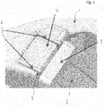
- Figure 1 shows a detail view of the housing 1 of the throttle flap connector and of the toothed ring 2, which transmits the movement of the actuator (not shown) to the throttle flap (likewise not shown).
- the housing 1 has a cutout 3 which forms a receptacle for the permanent magnet 4.
- a magnetic counterpart 5 On the toothed ring 2, at the end region facing toward the cutout 3, there is arranged a magnetic counterpart 5 which can be moved toward the permanent magnet as a result of the rotation of the throttle flap about the axis of rotation.
- the magnetic counterpart 5 is in particular manufactured from a magnetic material on which the magnetic force of the permanent magnet 4 can act when said magnetic counterpart enters the area of action of the magnetic field.
- the permanent magnet 4 is encompassed laterally by plates 6 which serve for directing and focusing the magnetic field.
- the magnetic field of the permanent magnet 4 can be directed so as to be oriented in the direction of the magnetic counterpart 5. This has the effect that the magnetic field extends over a greater distance than in the case of a permanent magnet without the plates. It is thus possible for the magnetic counterpart 5 to enter the area of action of the permanent magnets 4 at an earlier point in time, whereby the action is intensified.
- the magnetic counterpart 5 can be attracted, whereby the throttle flap connected to the magnetic counterpart 5 by means of the toothed ring 3 is also attracted, or is rotated further about its axis of rotation.
- the permanent magnet 4 or the cutout 3 thus act as a stop for the throttle flap.
- an end position for the throttle flap may for example completely close the flow cross section, completely open up said flow cross section, or assume a defined intermediate position.
- figure 1 is in particular not of a restrictive nature, and serves for illustrating the concept of the invention.
Landscapes
- Engineering & Computer Science (AREA)
- Chemical & Material Sciences (AREA)
- Combustion & Propulsion (AREA)
- Mechanical Engineering (AREA)
- General Engineering & Computer Science (AREA)
- Control Of Throttle Valves Provided In The Intake System Or In The Exhaust System (AREA)
Abstract
Description
- The invention relates to a valve for regulating a flow cross section in a throttle flap connector, having a throttle flap which is mounted in the throttle flap connector so as to be rotatable about an axis of rotation, wherein the throttle flap is rotatable about the axis of rotation, by means of an actuator which acts on the throttle flap, counter to a force generated by a mechanical spring.
- Throttle flaps are used for example in the intake tract of internal combustion engines for the purposes of regulating the air quantity to be supplied to the combustion chamber. Through the use of a throttle flap, it is possible in particular for the supplied air quantity to be adapted to the supplied fuel quantity, and/or for an air-fuel mixture suitable for the respective load state of the internal combustion engine to be generated.
- Throttle flaps in throttle flap connectors are known.
DE 195 12 729 A1 describes a throttle flap connector with a tubular housing in which a throttle flap is fastened to a throttle flap shaft which, at its free ends led through recesses in the housing wall, is mounted so as to be rotatable transversely with respect to the longitudinal axis of the tubular housing. - Throttle flaps can be rotated in their throttle flap connector by means of an actuator, such as for example an electric motor. As a result of the rotation of the throttle flap relative to the throttle flap connector, the flow cross section of the throttle flap connector can be increased and decreased in size. Often, throttle flaps are designed so as to be held open by a mechanical spring when not acted on by the actuator. Here, the actuator is used to close the throttle flap, through the application of a force, counter to the spring force acting on said throttle flap.
- A disadvantage of devices in the prior art is in particular that the closed position of the throttle flap can be maintained only if the actuator remains energized and thus exerts on the throttle flap a force which counteracts the force imparted by the mechanical spring.
- Presentation of the invention, problem, solution, advantages
- Therefore, the problem addressed by the present invention is that of creating a throttle flap arranged in a throttle flap connector, which throttle flap can be held in a defined position even in the presence of a reduced action of the actuator or in the absence of action of the actuator.
- The problem is solved, with regard to the valve, by means of a valve having the features of claim 1.
- An exemplary embodiment of the invention relates to a valve for regulating a flow cross section in a throttle flap connector, having a throttle flap which is mounted in the throttle flap connector so as to be rotatable about an axis of rotation, wherein the throttle flap is rotatable about the axis of rotation, by means of an actuator which acts on the throttle flap, counter to a force generated by a mechanical spring, wherein the throttle flap, in at least a first position, is fixable in said first position by means of a magnet device, wherein the magnet device is formed by a permanent magnet and a magnetic counterpart, wherein the permanent magnet is arranged in the housing of the throttle flap connector and the magnetic counterpart is arranged on an element which is rotatable with the throttle flap.
- The valve is formed by a tubular throttle flap connector in which a throttle flap is rotatably mounted. As a result of the rotation of the throttle flap, the cross section, through which flow can pass, of the throttle flap connector can be increased or decreased in size. In the two maximum positions, the throttle flap completely respectively closes the flow cross section of the throttle flap connector or opens up the flow cross section of the throttle flap connector by being rotated so as to be oriented parallel to the main throughflow direction.
- The throttle flap is acted on by a mechanical spring with a force which rotates the throttle flap either toward the open position or toward the closed position. Furthermore, an actuator, for example an electric motor, is provided, which can exert on the throttle flap a force directed counter to the mechanical spring. Depending on the arrangement of the mechanical spring and of the actuator, the throttle flap can be either open or closed by means of the mechanical spring, wherein the actuator acts in each case in the opposite direction.
- To be able to advantageously fix the throttle flap in a defined position, a magnet device is provided. Said first position is particularly preferably characterized by the fully closed position of the throttle flap or by the fully open position.
- A permanent magnet is particularly advantageously arranged on the throttle flap connector, which permanent magnet magnetically interacts with a magnetic counterpart which is mounted on the throttle flap itself.
- It is particularly advantageous if the permanent magnet is surrounded by means for directing the magnetic field, which means increase the magnetic force of the permanent magnet in at least one direction. Said means are advantageous for directing and focusing the magnetic field generated by the respective permanent magnet, in order to thereby achieve the same action with a smaller permanent magnet or to transmit the magnetic force over a greater distance.
- It is also advantageous if the means for directing the magnetic field are formed by metal plates which are arranged between the permanent magnet and the housing of the throttle flap connector. Metal plates can, if produced from a magnetic metal, be utilized for directing and focusing the field lines originating from the permanent magnet. This is based on the magnetic characteristics of the metal.
- It is furthermore advantageous if the means for directing the magnetic field are formed by steel elements. Steel is particularly advantageous because it can be procured cheaply in an extremely wide range of variants and is furthermore easy to machine. In this way, the magnetic field can be influenced in a particularly simple manner.
- A preferred exemplary embodiment is characterized in that the magnetic counterpart is movable on a circular path formed around the axis of rotation, wherein the spacing between the permanent magnet and the magnetic counterpart in a circumferential direction along the circular path is defined by the angle of rotation of the throttle flap. The arrangement of the permanent magnet and of the magnetic counterpart on a common circular path is advantageous for ensuring that the two elements can be moved toward one another or away from one another in a defined manner as a result of the rotation of the throttle flap. The circular path advantageously runs around the axis of rotation of the throttle flap.
- It is also preferable if the housing of the throttle flap connector has a cutout which is open at least on one side and into which the permanent magnet and the means for directing the magnetic field are inserted. An arrangement of the permanent magnet on the housing of the throttle flap connector is advantageous because the permanent magnet is thus positionally fixed and is in particular not adversely affected by the inertia of the throttle flap.
- It is furthermore advantageous if that side of the cutout which is open on one side is at least partially covered, in at least one position of the throttle flap, by the magnetic counterpart. The cutout is advantageously located such that the opening through which the permanent magnet is inserted can be partially or entirely covered by the magnetic counterpart. This is necessary in order to impart the best possible action on the magnetic counterpart, because the magnetic field lines can propagate unhindered through the opening.
- It is also expedient if the magnetic counterpart is part of the toothed ring by means of which the movement of the actuator can be transmitted to the throttle flap. This is particularly advantageous because the toothed ring that is generally used for transmitting the movement of the actuator to the throttle flap moves in the same direction as, and in a manner directly dependent on, the throttle flap.
- It is furthermore advantageous if the throttle flap is rotatable between two maximum positions, wherein, in the first maximum position, the throttle flap closes the flow cross section of the throttle flap connector, and in the second maximum position, the throttle flap opens up the flow cross section of the throttle flap connector.
- It is furthermore expedient if the throttle flap, in the first position in which it is fixable by means of the magnet device, completely closes the flow cross section of the throttle flap connector. This is particularly advantageous if the throttle flap is constructed such that the mechanical spring opens the throttle flap and the actuator closes the throttle flap. Here, by means of the magnet device, the throttle flap can be fixed in the closed position even when the actuator exerts no force, or only a reduced force, on the throttle flap.
- It is also advantageous if the force generated by the magnet device for holding the throttle flap in the first position is at least equal to or greater than the force generated by the mechanical spring. This applies in particular if the magnetic device exerts a force which is directed counter to the force of the mechanical spring.
- Advantageous refinements of the present invention are described in the subclaims and in the following description of the figures.
- Below, the invention will be discussed in detail on the basis of an exemplary embodiment and with reference to the drawing, in which:
- figure 1
- shows a perspective view of the cutout into which the permanent magnet is inserted and the magnetic counterpart on the throttle flap, wherein the permanent magnet is encompassed by means for directing the magnetic field.
-
Figure 1 shows a detail view of the housing 1 of the throttle flap connector and of thetoothed ring 2, which transmits the movement of the actuator (not shown) to the throttle flap (likewise not shown). - The housing 1 has a
cutout 3 which forms a receptacle for thepermanent magnet 4. On thetoothed ring 2, at the end region facing toward thecutout 3, there is arranged amagnetic counterpart 5 which can be moved toward the permanent magnet as a result of the rotation of the throttle flap about the axis of rotation. - The
magnetic counterpart 5 is in particular manufactured from a magnetic material on which the magnetic force of thepermanent magnet 4 can act when said magnetic counterpart enters the area of action of the magnetic field. - The
permanent magnet 4 is encompassed laterally by plates 6 which serve for directing and focusing the magnetic field. By means of the plates 6, the magnetic field of thepermanent magnet 4 can be directed so as to be oriented in the direction of themagnetic counterpart 5. This has the effect that the magnetic field extends over a greater distance than in the case of a permanent magnet without the plates. It is thus possible for themagnetic counterpart 5 to enter the area of action of thepermanent magnets 4 at an earlier point in time, whereby the action is intensified. - By means of the
permanent magnet 4, themagnetic counterpart 5 can be attracted, whereby the throttle flap connected to themagnetic counterpart 5 by means of thetoothed ring 3 is also attracted, or is rotated further about its axis of rotation. When themagnetic counterpart 5 comes into contact with thepermanent magnet 4 or with thecutout 3, the movement of the throttle flap is delimited. Thepermanent magnet 4 or thecutout 3 thus act as a stop for the throttle flap. Depending on the positioning of thepermanent magnet 4 or of thestop 3 relative to the position of the throttle flap or of the angle of rotation thereof, it is thus possible for an end position for the throttle flap to be defined. Here, in the end position thus defined, the throttle flap may for example completely close the flow cross section, completely open up said flow cross section, or assume a defined intermediate position. - The exemplary embodiment of
figure 1 is in particular not of a restrictive nature, and serves for illustrating the concept of the invention.
Claims (10)
- A valve for regulating a flow cross section in a throttle flap connector, having a throttle flap which is mounted in the throttle flap connector so as to be rotatable about an axis of rotation, wherein the throttle flap is rotatable about the axis of rotation, by means of an actuator which acts on the throttle flap, counter to a force generated by a mechanical spring, characterized in that the throttle flap, in at least a first position, is fixable in said first position by means of a magnet device (4, 5), wherein the magnet device (4, 5) is formed by a permanent magnet (4) and a magnetic counterpart (5), wherein the permanent magnet (4) is arranged in the housing (1) of the throttle flap connector and the magnetic counterpart (5) is arranged on an element (2) which is rotatable with the throttle flap.
- The valve as claimed in claim 1, characterized in that the permanent magnet (4) is surrounded by means (6) for directing the magnetic field, which means increase the magnetic force of the permanent magnet (4) in at least one direction.
- The valve as claimed in one of the preceding claims, characterized in that the means (6) for directing the magnetic field are formed by metal plates (6) which are arranged between the permanent magnet (4) and the housing (1) of the throttle flap connector.
- The valve as claimed in one of the preceding claims, characterized in that the magnetic counterpart (5) is movable on a circular path formed around the axis of rotation, wherein the spacing between the permanent magnet (4) and the magnetic counterpart (5) in a circumferential direction along the circular path is defined by the angle of rotation of the throttle flap.
- The valve as claimed in one of the preceding claims, characterized in that the housing (1) of the throttle flap connector has a cutout (3) which is open at least on one side and into which the permanent magnet (4) and the means (6) for directing the magnetic field are inserted.
- The valve as claimed in one of the preceding claims, characterized in that that side of the cutout (3) which is open on one side is at least partially covered, in at least one position of the throttle flap, by the magnetic counterpart (5).
- The valve as claimed in one of the preceding claims, characterized in that the means (6) for directing the magnetic field are formed by steel elements (6).
- The valve as claimed in one of the preceding claims, characterized in that the magnetic counterpart (5) is part of the toothed ring (2) by means of which the movement of the actuator can be transmitted to the throttle flap.
- The valve as claimed in one of the preceding claims, characterized in that the throttle flap, in the first position in which it is fixable by means of the magnet device (4, 5), completely closes the flow cross section of the throttle flap connector.
- The valve as claimed in one of the preceding claims, characterized in that the force generated by the magnet device (4, 5) for holding the throttle flap in the first position is at least equal to or greater than the force generated by the mechanical spring.
Priority Applications (2)
| Application Number | Priority Date | Filing Date | Title |
|---|---|---|---|
| EP17465521.7A EP3401534B1 (en) | 2017-05-10 | 2017-05-10 | Valve having a throttle flap arranged in a throttle flap connector |
| PCT/EP2018/062086 WO2018206687A1 (en) | 2017-05-10 | 2018-05-09 | Valve having a throttle flap arranged in a throttle flap connector |
Applications Claiming Priority (1)
| Application Number | Priority Date | Filing Date | Title |
|---|---|---|---|
| EP17465521.7A EP3401534B1 (en) | 2017-05-10 | 2017-05-10 | Valve having a throttle flap arranged in a throttle flap connector |
Publications (2)
| Publication Number | Publication Date |
|---|---|
| EP3401534A1 true EP3401534A1 (en) | 2018-11-14 |
| EP3401534B1 EP3401534B1 (en) | 2020-07-08 |
Family
ID=58779055
Family Applications (1)
| Application Number | Title | Priority Date | Filing Date |
|---|---|---|---|
| EP17465521.7A Active EP3401534B1 (en) | 2017-05-10 | 2017-05-10 | Valve having a throttle flap arranged in a throttle flap connector |
Country Status (2)
| Country | Link |
|---|---|
| EP (1) | EP3401534B1 (en) |
| WO (1) | WO2018206687A1 (en) |
Cited By (1)
| Publication number | Priority date | Publication date | Assignee | Title |
|---|---|---|---|---|
| EP3633248A1 (en) * | 2018-10-02 | 2020-04-08 | Continental Automotive GmbH | Valve for controlling exhaust gas or fresh air in a drive unit |
Citations (6)
| Publication number | Priority date | Publication date | Assignee | Title |
|---|---|---|---|---|
| GB2232274A (en) * | 1989-06-01 | 1990-12-05 | Pei Qui Mao | Valve |
| US5092296A (en) * | 1989-08-22 | 1992-03-03 | Robert Bosch Gmbh | Apparatus with a throttle device determining the output of a prime mover |
| DE19512729A1 (en) | 1995-04-05 | 1996-10-10 | Vdo Schindling | Butterfly valve giving good fitting in pipe when closed |
| JPH10160027A (en) * | 1996-11-26 | 1998-06-16 | Nissan Motor Co Ltd | Magnetic spring device |
| DE10143835A1 (en) * | 2001-09-07 | 2003-03-27 | Pierburg Gmbh | Valve adjuster, e.g. for choke flap valves, exhaust gas feedback valves, has magnetic adjustment element whose movement increases force between restoring device magnetic elements |
| US6779775B2 (en) * | 2002-07-31 | 2004-08-24 | Ab Elektronik Gmbh | Air flap system with a magnetic positioning spring |
-
2017
- 2017-05-10 EP EP17465521.7A patent/EP3401534B1/en active Active
-
2018
- 2018-05-09 WO PCT/EP2018/062086 patent/WO2018206687A1/en not_active Ceased
Patent Citations (6)
| Publication number | Priority date | Publication date | Assignee | Title |
|---|---|---|---|---|
| GB2232274A (en) * | 1989-06-01 | 1990-12-05 | Pei Qui Mao | Valve |
| US5092296A (en) * | 1989-08-22 | 1992-03-03 | Robert Bosch Gmbh | Apparatus with a throttle device determining the output of a prime mover |
| DE19512729A1 (en) | 1995-04-05 | 1996-10-10 | Vdo Schindling | Butterfly valve giving good fitting in pipe when closed |
| JPH10160027A (en) * | 1996-11-26 | 1998-06-16 | Nissan Motor Co Ltd | Magnetic spring device |
| DE10143835A1 (en) * | 2001-09-07 | 2003-03-27 | Pierburg Gmbh | Valve adjuster, e.g. for choke flap valves, exhaust gas feedback valves, has magnetic adjustment element whose movement increases force between restoring device magnetic elements |
| US6779775B2 (en) * | 2002-07-31 | 2004-08-24 | Ab Elektronik Gmbh | Air flap system with a magnetic positioning spring |
Cited By (1)
| Publication number | Priority date | Publication date | Assignee | Title |
|---|---|---|---|---|
| EP3633248A1 (en) * | 2018-10-02 | 2020-04-08 | Continental Automotive GmbH | Valve for controlling exhaust gas or fresh air in a drive unit |
Also Published As
| Publication number | Publication date |
|---|---|
| WO2018206687A1 (en) | 2018-11-15 |
| EP3401534B1 (en) | 2020-07-08 |
Similar Documents
| Publication | Publication Date | Title |
|---|---|---|
| US7503309B2 (en) | Throttle control apparatus | |
| CN107849984B (en) | Torsion spring | |
| US9784225B2 (en) | Intake air control apparatus of engine | |
| JP5971276B2 (en) | Actuator and assembly method thereof | |
| US20030196638A1 (en) | Throttle system for general-purpose engine | |
| EP3401534B1 (en) | Valve having a throttle flap arranged in a throttle flap connector | |
| US11306665B2 (en) | Throttle device | |
| JP2010116796A (en) | Intake air-flow control device for internal combustion engine | |
| EP3346114B1 (en) | Throttle valve control device | |
| CN104271932B (en) | Mixing valve of an internal combustion engine | |
| EP3401533B1 (en) | Valve having a throttle flap arranged in a throttle flap connector | |
| US4321571A (en) | Rotary actuator with selectable response characteristics | |
| JP2012041887A (en) | Electronic throttle | |
| EP3904662B1 (en) | Throttle device | |
| US6779775B2 (en) | Air flap system with a magnetic positioning spring | |
| JP6472742B2 (en) | Throttle device | |
| EP3401532B1 (en) | Valve having a throttle flap arranged in a throttle flap connector | |
| WO2017057080A1 (en) | Torsion spring | |
| JP2019138290A (en) | Permanent magnet, opening detection device, and throttle device | |
| JP6700913B2 (en) | Intake control device | |
| JP2020020321A (en) | Intake device of internal combustion engine | |
| US10557420B2 (en) | Fresh air supply device for an internal combustion engine of a motor vehicle | |
| JP2024064137A (en) | Throttle device and intake system | |
| JP2025102552A (en) | Throttle device and intake system of internal combustion engine | |
| CN112639269A (en) | Throttle device of general engine |
Legal Events
| Date | Code | Title | Description |
|---|---|---|---|
| PUAI | Public reference made under article 153(3) epc to a published international application that has entered the european phase |
Free format text: ORIGINAL CODE: 0009012 |
|
| STAA | Information on the status of an ep patent application or granted ep patent |
Free format text: STATUS: THE APPLICATION HAS BEEN PUBLISHED |
|
| AK | Designated contracting states |
Kind code of ref document: A1 Designated state(s): AL AT BE BG CH CY CZ DE DK EE ES FI FR GB GR HR HU IE IS IT LI LT LU LV MC MK MT NL NO PL PT RO RS SE SI SK SM TR |
|
| AX | Request for extension of the european patent |
Extension state: BA ME |
|
| STAA | Information on the status of an ep patent application or granted ep patent |
Free format text: STATUS: REQUEST FOR EXAMINATION WAS MADE |
|
| 17P | Request for examination filed |
Effective date: 20190514 |
|
| RBV | Designated contracting states (corrected) |
Designated state(s): AL AT BE BG CH CY CZ DE DK EE ES FI FR GB GR HR HU IE IS IT LI LT LU LV MC MK MT NL NO PL PT RO RS SE SI SK SM TR |
|
| GRAP | Despatch of communication of intention to grant a patent |
Free format text: ORIGINAL CODE: EPIDOSNIGR1 |
|
| STAA | Information on the status of an ep patent application or granted ep patent |
Free format text: STATUS: GRANT OF PATENT IS INTENDED |
|
| INTG | Intention to grant announced |
Effective date: 20191218 |
|
| GRAS | Grant fee paid |
Free format text: ORIGINAL CODE: EPIDOSNIGR3 |
|
| RAP1 | Party data changed (applicant data changed or rights of an application transferred) |
Owner name: VITESCO TECHNOLOGIES GMBH |
|
| GRAA | (expected) grant |
Free format text: ORIGINAL CODE: 0009210 |
|
| STAA | Information on the status of an ep patent application or granted ep patent |
Free format text: STATUS: THE PATENT HAS BEEN GRANTED |
|
| AK | Designated contracting states |
Kind code of ref document: B1 Designated state(s): AL AT BE BG CH CY CZ DE DK EE ES FI FR GB GR HR HU IE IS IT LI LT LU LV MC MK MT NL NO PL PT RO RS SE SI SK SM TR |
|
| REG | Reference to a national code |
Ref country code: CH Ref legal event code: EP Ref country code: AT Ref legal event code: REF Ref document number: 1288706 Country of ref document: AT Kind code of ref document: T Effective date: 20200715 |
|
| REG | Reference to a national code |
Ref country code: DE Ref legal event code: R096 Ref document number: 602017019328 Country of ref document: DE |
|
| REG | Reference to a national code |
Ref country code: IE Ref legal event code: FG4D |
|
| REG | Reference to a national code |
Ref country code: LT Ref legal event code: MG4D |
|
| REG | Reference to a national code |
Ref country code: AT Ref legal event code: MK05 Ref document number: 1288706 Country of ref document: AT Kind code of ref document: T Effective date: 20200708 |
|
| REG | Reference to a national code |
Ref country code: NL Ref legal event code: MP Effective date: 20200708 |
|
| PG25 | Lapsed in a contracting state [announced via postgrant information from national office to epo] |
Ref country code: FI Free format text: LAPSE BECAUSE OF FAILURE TO SUBMIT A TRANSLATION OF THE DESCRIPTION OR TO PAY THE FEE WITHIN THE PRESCRIBED TIME-LIMIT Effective date: 20200708 Ref country code: LT Free format text: LAPSE BECAUSE OF FAILURE TO SUBMIT A TRANSLATION OF THE DESCRIPTION OR TO PAY THE FEE WITHIN THE PRESCRIBED TIME-LIMIT Effective date: 20200708 Ref country code: HR Free format text: LAPSE BECAUSE OF FAILURE TO SUBMIT A TRANSLATION OF THE DESCRIPTION OR TO PAY THE FEE WITHIN THE PRESCRIBED TIME-LIMIT Effective date: 20200708 Ref country code: SE Free format text: LAPSE BECAUSE OF FAILURE TO SUBMIT A TRANSLATION OF THE DESCRIPTION OR TO PAY THE FEE WITHIN THE PRESCRIBED TIME-LIMIT Effective date: 20200708 Ref country code: ES Free format text: LAPSE BECAUSE OF FAILURE TO SUBMIT A TRANSLATION OF THE DESCRIPTION OR TO PAY THE FEE WITHIN THE PRESCRIBED TIME-LIMIT Effective date: 20200708 Ref country code: NO Free format text: LAPSE BECAUSE OF FAILURE TO SUBMIT A TRANSLATION OF THE DESCRIPTION OR TO PAY THE FEE WITHIN THE PRESCRIBED TIME-LIMIT Effective date: 20201008 Ref country code: GR Free format text: LAPSE BECAUSE OF FAILURE TO SUBMIT A TRANSLATION OF THE DESCRIPTION OR TO PAY THE FEE WITHIN THE PRESCRIBED TIME-LIMIT Effective date: 20201009 Ref country code: AT Free format text: LAPSE BECAUSE OF FAILURE TO SUBMIT A TRANSLATION OF THE DESCRIPTION OR TO PAY THE FEE WITHIN THE PRESCRIBED TIME-LIMIT Effective date: 20200708 Ref country code: PT Free format text: LAPSE BECAUSE OF FAILURE TO SUBMIT A TRANSLATION OF THE DESCRIPTION OR TO PAY THE FEE WITHIN THE PRESCRIBED TIME-LIMIT Effective date: 20201109 Ref country code: BG Free format text: LAPSE BECAUSE OF FAILURE TO SUBMIT A TRANSLATION OF THE DESCRIPTION OR TO PAY THE FEE WITHIN THE PRESCRIBED TIME-LIMIT Effective date: 20201008 |
|
| PG25 | Lapsed in a contracting state [announced via postgrant information from national office to epo] |
Ref country code: RS Free format text: LAPSE BECAUSE OF FAILURE TO SUBMIT A TRANSLATION OF THE DESCRIPTION OR TO PAY THE FEE WITHIN THE PRESCRIBED TIME-LIMIT Effective date: 20200708 Ref country code: PL Free format text: LAPSE BECAUSE OF FAILURE TO SUBMIT A TRANSLATION OF THE DESCRIPTION OR TO PAY THE FEE WITHIN THE PRESCRIBED TIME-LIMIT Effective date: 20200708 Ref country code: LV Free format text: LAPSE BECAUSE OF FAILURE TO SUBMIT A TRANSLATION OF THE DESCRIPTION OR TO PAY THE FEE WITHIN THE PRESCRIBED TIME-LIMIT Effective date: 20200708 Ref country code: IS Free format text: LAPSE BECAUSE OF FAILURE TO SUBMIT A TRANSLATION OF THE DESCRIPTION OR TO PAY THE FEE WITHIN THE PRESCRIBED TIME-LIMIT Effective date: 20201108 |
|
| PG25 | Lapsed in a contracting state [announced via postgrant information from national office to epo] |
Ref country code: NL Free format text: LAPSE BECAUSE OF FAILURE TO SUBMIT A TRANSLATION OF THE DESCRIPTION OR TO PAY THE FEE WITHIN THE PRESCRIBED TIME-LIMIT Effective date: 20200708 |
|
| REG | Reference to a national code |
Ref country code: DE Ref legal event code: R097 Ref document number: 602017019328 Country of ref document: DE |
|
| PG25 | Lapsed in a contracting state [announced via postgrant information from national office to epo] |
Ref country code: IT Free format text: LAPSE BECAUSE OF FAILURE TO SUBMIT A TRANSLATION OF THE DESCRIPTION OR TO PAY THE FEE WITHIN THE PRESCRIBED TIME-LIMIT Effective date: 20200708 Ref country code: EE Free format text: LAPSE BECAUSE OF FAILURE TO SUBMIT A TRANSLATION OF THE DESCRIPTION OR TO PAY THE FEE WITHIN THE PRESCRIBED TIME-LIMIT Effective date: 20200708 Ref country code: SM Free format text: LAPSE BECAUSE OF FAILURE TO SUBMIT A TRANSLATION OF THE DESCRIPTION OR TO PAY THE FEE WITHIN THE PRESCRIBED TIME-LIMIT Effective date: 20200708 Ref country code: RO Free format text: LAPSE BECAUSE OF FAILURE TO SUBMIT A TRANSLATION OF THE DESCRIPTION OR TO PAY THE FEE WITHIN THE PRESCRIBED TIME-LIMIT Effective date: 20200708 Ref country code: DK Free format text: LAPSE BECAUSE OF FAILURE TO SUBMIT A TRANSLATION OF THE DESCRIPTION OR TO PAY THE FEE WITHIN THE PRESCRIBED TIME-LIMIT Effective date: 20200708 Ref country code: CZ Free format text: LAPSE BECAUSE OF FAILURE TO SUBMIT A TRANSLATION OF THE DESCRIPTION OR TO PAY THE FEE WITHIN THE PRESCRIBED TIME-LIMIT Effective date: 20200708 |
|
| PLBE | No opposition filed within time limit |
Free format text: ORIGINAL CODE: 0009261 |
|
| STAA | Information on the status of an ep patent application or granted ep patent |
Free format text: STATUS: NO OPPOSITION FILED WITHIN TIME LIMIT |
|
| PG25 | Lapsed in a contracting state [announced via postgrant information from national office to epo] |
Ref country code: AL Free format text: LAPSE BECAUSE OF FAILURE TO SUBMIT A TRANSLATION OF THE DESCRIPTION OR TO PAY THE FEE WITHIN THE PRESCRIBED TIME-LIMIT Effective date: 20200708 |
|
| 26N | No opposition filed |
Effective date: 20210409 |
|
| PG25 | Lapsed in a contracting state [announced via postgrant information from national office to epo] |
Ref country code: SK Free format text: LAPSE BECAUSE OF FAILURE TO SUBMIT A TRANSLATION OF THE DESCRIPTION OR TO PAY THE FEE WITHIN THE PRESCRIBED TIME-LIMIT Effective date: 20200708 |
|
| PG25 | Lapsed in a contracting state [announced via postgrant information from national office to epo] |
Ref country code: SI Free format text: LAPSE BECAUSE OF FAILURE TO SUBMIT A TRANSLATION OF THE DESCRIPTION OR TO PAY THE FEE WITHIN THE PRESCRIBED TIME-LIMIT Effective date: 20200708 |
|
| REG | Reference to a national code |
Ref country code: CH Ref legal event code: PL |
|
| REG | Reference to a national code |
Ref country code: DE Ref legal event code: R081 Ref document number: 602017019328 Country of ref document: DE Owner name: SCHAEFFLER TECHNOLOGIES AG & CO. KG, DE Free format text: FORMER OWNER: VITESCO TECHNOLOGIES GMBH, 30165 HANNOVER, DE Ref country code: DE Ref legal event code: R081 Ref document number: 602017019328 Country of ref document: DE Owner name: VITESCO TECHNOLOGIES GMBH, DE Free format text: FORMER OWNER: VITESCO TECHNOLOGIES GMBH, 30165 HANNOVER, DE |
|
| GBPC | Gb: european patent ceased through non-payment of renewal fee |
Effective date: 20210510 |
|
| PG25 | Lapsed in a contracting state [announced via postgrant information from national office to epo] |
Ref country code: CH Free format text: LAPSE BECAUSE OF NON-PAYMENT OF DUE FEES Effective date: 20210531 Ref country code: LI Free format text: LAPSE BECAUSE OF NON-PAYMENT OF DUE FEES Effective date: 20210531 Ref country code: MC Free format text: LAPSE BECAUSE OF FAILURE TO SUBMIT A TRANSLATION OF THE DESCRIPTION OR TO PAY THE FEE WITHIN THE PRESCRIBED TIME-LIMIT Effective date: 20200708 Ref country code: LU Free format text: LAPSE BECAUSE OF NON-PAYMENT OF DUE FEES Effective date: 20210510 |
|
| REG | Reference to a national code |
Ref country code: BE Ref legal event code: MM Effective date: 20210531 |
|
| PG25 | Lapsed in a contracting state [announced via postgrant information from national office to epo] |
Ref country code: IE Free format text: LAPSE BECAUSE OF NON-PAYMENT OF DUE FEES Effective date: 20210510 Ref country code: GB Free format text: LAPSE BECAUSE OF NON-PAYMENT OF DUE FEES Effective date: 20210510 |
|
| PG25 | Lapsed in a contracting state [announced via postgrant information from national office to epo] |
Ref country code: BE Free format text: LAPSE BECAUSE OF NON-PAYMENT OF DUE FEES Effective date: 20210531 |
|
| PG25 | Lapsed in a contracting state [announced via postgrant information from national office to epo] |
Ref country code: CY Free format text: LAPSE BECAUSE OF FAILURE TO SUBMIT A TRANSLATION OF THE DESCRIPTION OR TO PAY THE FEE WITHIN THE PRESCRIBED TIME-LIMIT Effective date: 20200708 |
|
| P01 | Opt-out of the competence of the unified patent court (upc) registered |
Effective date: 20230530 |
|
| PG25 | Lapsed in a contracting state [announced via postgrant information from national office to epo] |
Ref country code: HU Free format text: LAPSE BECAUSE OF FAILURE TO SUBMIT A TRANSLATION OF THE DESCRIPTION OR TO PAY THE FEE WITHIN THE PRESCRIBED TIME-LIMIT; INVALID AB INITIO Effective date: 20170510 |
|
| PG25 | Lapsed in a contracting state [announced via postgrant information from national office to epo] |
Ref country code: MK Free format text: LAPSE BECAUSE OF FAILURE TO SUBMIT A TRANSLATION OF THE DESCRIPTION OR TO PAY THE FEE WITHIN THE PRESCRIBED TIME-LIMIT Effective date: 20200708 |
|
| PG25 | Lapsed in a contracting state [announced via postgrant information from national office to epo] |
Ref country code: TR Free format text: LAPSE BECAUSE OF FAILURE TO SUBMIT A TRANSLATION OF THE DESCRIPTION OR TO PAY THE FEE WITHIN THE PRESCRIBED TIME-LIMIT Effective date: 20200708 |
|
| PG25 | Lapsed in a contracting state [announced via postgrant information from national office to epo] |
Ref country code: MT Free format text: LAPSE BECAUSE OF FAILURE TO SUBMIT A TRANSLATION OF THE DESCRIPTION OR TO PAY THE FEE WITHIN THE PRESCRIBED TIME-LIMIT Effective date: 20200708 |
|
| REG | Reference to a national code |
Ref country code: DE Ref legal event code: R081 Ref document number: 602017019328 Country of ref document: DE Owner name: SCHAEFFLER TECHNOLOGIES AG & CO. KG, DE Free format text: FORMER OWNER: VITESCO TECHNOLOGIES GMBH, 93055 REGENSBURG, DE |
|
| PGFP | Annual fee paid to national office [announced via postgrant information from national office to epo] |
Ref country code: DE Payment date: 20250531 Year of fee payment: 9 |
|
| PGFP | Annual fee paid to national office [announced via postgrant information from national office to epo] |
Ref country code: FR Payment date: 20250528 Year of fee payment: 9 |