EP3401170A1 - Braking device - Google Patents
Braking device Download PDFInfo
- Publication number
- EP3401170A1 EP3401170A1 EP18171889.1A EP18171889A EP3401170A1 EP 3401170 A1 EP3401170 A1 EP 3401170A1 EP 18171889 A EP18171889 A EP 18171889A EP 3401170 A1 EP3401170 A1 EP 3401170A1
- Authority
- EP
- European Patent Office
- Prior art keywords
- command means
- command
- braking
- result
- rotation
- Prior art date
- Legal status (The legal status is an assumption and is not a legal conclusion. Google has not performed a legal analysis and makes no representation as to the accuracy of the status listed.)
- Granted
Links
Images




Classifications
-
- B—PERFORMING OPERATIONS; TRANSPORTING
- B60—VEHICLES IN GENERAL
- B60T—VEHICLE BRAKE CONTROL SYSTEMS OR PARTS THEREOF; BRAKE CONTROL SYSTEMS OR PARTS THEREOF, IN GENERAL; ARRANGEMENT OF BRAKING ELEMENTS ON VEHICLES IN GENERAL; PORTABLE DEVICES FOR PREVENTING UNWANTED MOVEMENT OF VEHICLES; VEHICLE MODIFICATIONS TO FACILITATE COOLING OF BRAKES
- B60T7/00—Brake-action initiating means
- B60T7/02—Brake-action initiating means for personal initiation
- B60T7/08—Brake-action initiating means for personal initiation hand actuated
- B60T7/10—Disposition of hand control
- B60T7/102—Disposition of hand control by means of a tilting lever
-
- B—PERFORMING OPERATIONS; TRANSPORTING
- B60—VEHICLES IN GENERAL
- B60T—VEHICLE BRAKE CONTROL SYSTEMS OR PARTS THEREOF; BRAKE CONTROL SYSTEMS OR PARTS THEREOF, IN GENERAL; ARRANGEMENT OF BRAKING ELEMENTS ON VEHICLES IN GENERAL; PORTABLE DEVICES FOR PREVENTING UNWANTED MOVEMENT OF VEHICLES; VEHICLE MODIFICATIONS TO FACILITATE COOLING OF BRAKES
- B60T11/00—Transmitting braking action from initiating means to ultimate brake actuator without power assistance or drive or where such assistance or drive is irrelevant
- B60T11/10—Transmitting braking action from initiating means to ultimate brake actuator without power assistance or drive or where such assistance or drive is irrelevant transmitting by fluid means, e.g. hydraulic
- B60T11/108—Transmitting braking action from initiating means to ultimate brake actuator without power assistance or drive or where such assistance or drive is irrelevant transmitting by fluid means, e.g. hydraulic to a trailer fluid system
-
- B—PERFORMING OPERATIONS; TRANSPORTING
- B60—VEHICLES IN GENERAL
- B60T—VEHICLE BRAKE CONTROL SYSTEMS OR PARTS THEREOF; BRAKE CONTROL SYSTEMS OR PARTS THEREOF, IN GENERAL; ARRANGEMENT OF BRAKING ELEMENTS ON VEHICLES IN GENERAL; PORTABLE DEVICES FOR PREVENTING UNWANTED MOVEMENT OF VEHICLES; VEHICLE MODIFICATIONS TO FACILITATE COOLING OF BRAKES
- B60T7/00—Brake-action initiating means
- B60T7/12—Brake-action initiating means for automatic initiation; for initiation not subject to will of driver or passenger
- B60T7/20—Brake-action initiating means for automatic initiation; for initiation not subject to will of driver or passenger specially for trailers, e.g. in case of uncoupling of or overrunning by trailer
Definitions
- the present invention relates to a braking device.
- a number of recently introduced regulations require that between a towing vehicle and the relative trailer a brake-trailer valve must be interposed provided with a pair of female couplings connectable to a pair of relative male couplings, where such female couplings are connectable to a control line which is adapted to supply the braking system of the trailer, and to an additional line which is adapted to deactivate the automatic and/or parking brake of the trailer respectively.
- the braking phases of a vehicle are generally three in number, i.e. the service braking, which occurs in normal operating conditions of the vehicle, the parking braking, i.e. when the vehicle is stationary in the same position, and the emergency braking.
- Document WO2016185327 describes a braking device according to the preamble of claim 1 of the present invention, which provides for a supporting body associable with the chassis of a towing vehicle, a command lever provided with a first portion, hinged to the supporting body and connected to first command means of the parking brake of the towing vehicle, and a second portion, hinged to the first portion and connected to second command means connected to the brake-trailer valve and activatable to send fluid under pressure along the relative control line.
- the first portion is also lifted, in such a way that during the emergency braking of the towing vehicle the trailer brakes gradually.
- This device also provides for third command means of the electrical type which are adapted to interact with the additional line of the brake-trailer valve to activate or deactivate the automatic and/or parking brake of the trailer.
- the third command means comprise two electric switches, one of which is adapted to interact with the first portion and is deactivated after the first portion is lifted, while the other can be activated by means of a button activatable manually by the operator and arranged on the second portion of the above-mentioned lever. This way, when the first and second portions are lifted (by operating the above-mentioned manual button) to activate the parking brake of the towing vehicle and the service brake of the trailer, the automatic and/or parking brake of the trailer remains inactive because one of the two electrical switches is activated.
- This braking device of known type does however have its drawbacks, inasmuch as because of the longitudinal extension of the lever itself, considerable force must be exerted to transmit the command to the corresponding switch, so that it is rather difficult to operate the third command means using the button located at the extremity of the second portion of the command lever.
- this solenoid valve can therefore be a limit to the use of this type of device, inasmuch as an electrical malfunction may cause the failure to activate of the automatic and/or parking brake of the trailer.
- the main aim of the present invention is to provide a single braking device which allows commanding the automatic and/or parking brake of the trailer safely and easily.
- one object of the present invention is to avoid that the activation of the automatic and/or parking brake of the trailer requires a great effort by the operator.
- one object of the present invention is to allow commanding the automatic and/or parking brake of the trailer without resorting to the aid of electrical components.
- Another object of the present invention is to facilitate, with respect to known devices, the management of the command of the parking brake F of the towing vehicle and of the service and parking braking of the trailer.
- Yet another object is to reduce the longitudinal dimensions of the command lever and to simplify the maneuvering action by the operator.
- the last object of the present invention is to provide a braking device which allows to overcome the mentioned drawbacks of the prior art within the ambit of a simple, rational, easy, effective to use and affordable solution.
- reference numeral 1 globally indicates a braking device.
- the device 1 comprises a base body 2, associable with the chassis of a towing vehicle, and at least one control apparatus 10 of the braking of a trailer which is adapted to adjust the pressure of a work fluid along a control line 7 connectable to the braking system of the trailer and along an additional line 11 operatively connected to the automatic and/or parking brake (not shown in the illustrations) of the trailer.
- the additional line 11 is under pressure the automatic and/or parking brake of the trailer is deactivated, whereas when the pressure along the same drops to zero the automatic and/or parking brake is activated.
- the device 1 then comprises first command means 3 associable with the parking brake of a towing vehicle (not shown in the illustrations) and actuatable for the operation of the same and second command means 5 connectable to the control apparatus 10 and adapted to adjust the pressure along the control line 7. More in detail, the second command means 5 are actuatable to send the work fluid under pressure along the control line 7, through the control apparatus 10, and thus operate the service braking of the trailer.
- the device 1 also comprises a lever 12 which has at least a first portion 12a hinged to the body 2, associated with the first command means 3 and movable between a home position, wherein the first command means 3 are deactivated, and at least a braking position, wherein it is rotated with respect to the home position and the first command means 3 are activated.
- the first portion 12a has a plurality of braking positions among which it moves continuously, by applying a gradually increasing force on the first command means 3.
- blocking means 13 of the first portion 12a are also provided in the braking position. More particularly, the blocking means 13 are adapted to maintain the first portion 12a in the braking position achieved from time to time and are removable by means of a suitable command 14 to enable the return of the first portion itself to the home position.
- the blocking means 13 are of the type of a ratchet lever and the command 14 is of the type of a button 14a which counteracts the elastic means 15, e.g. of the type of a spring, for lifting the lever and disengaging it from the teeth of the ratchet.
- the first command means 3 are of the mechanical type.
- the first command means 3 comprise at least a first flexible and inextensible cable, associated with the first portion 12a, which is adapted to pull the first cable itself as a result of its rotation from the home position towards the braking position.
- the lever 12 also comprises at least a second portion 12b, graspable by an operator, hinged to the first portion 12a, which is associated with the second command means 5 and movable between a home position, wherein the second command means 5 are deactivated, and at least a braking position, wherein it is rotated with respect to the home position and the second command means 5 are activated so as to operate the service braking of the trailer.
- the first portion 12a is hinged to the body 2 around an axis X of rotation and the second portion 12b is in turn hinged to the first portion 12a around the same axis X of rotation. Therefore, both the first and the second portions 12a and 12b rotate around the same axis X of rotation.
- the second portion 12b is fitted above the first portion 12a.
- the first portion 12a is arranged inside the second portion 12b.
- interconnection means 4 are provided, which are connected to the second portion 12b, which are adapted to interact with the first portion 12a as a result of the operation of the second portion 12b, to displace it to the relevant braking position.
- both the second portion 12b i.e. its lifting from the home position
- both the second portion itself and the first portion 12a move to a corresponding braking position by rotating around the axis X.
- the rotation of the second portion 12b around the axis X does in fact involve the exercising of a force on the first portion 12a through the interconnection means 4, which causes the rotation thereof around the axis X.
- This operating condition corresponds to an emergency condition, as a result of which both the parking brake of the towing vehicle and the service braking of the trailer are activated, as shown in Figure 4 .
- This operating condition corresponds to the parking condition, shown in Figure 6 , wherein the parking brake of the towing vehicle is activated and the service braking of the trailer is deactivated.
- the second command means 5 are of the mechanical type and comprise at least a second flexible and inextensible cable 18 associated with the second portion 12b, which is adapted to pull the second cable 18 as a result of its rotation towards the braking position.
- the pulling force applied on the second cable 18 increases.
- the interconnection means 4 comprise at least a first abutment element 4a associated with the second cable 18, e.g. of the type of a sheath which covers the second cable itself, and adapted to interact with the first portion 12a as a result of the achievement of a first predefined angle of rotation of the second portion 12b with respect to the first portion 12a.
- this rotates around the axis X with respect to the first portion 12a which, on the other hand, remains in the relative home position.
- the first abutment element 4a contacts the first portion itself, so that the further lifting of the second portion 12b also causes the first portion 12a to displace towards the relative braking position.
- the interconnection means 4 also comprise at least a second abutment element 4b associated with the second portion 12b and adapted to interact with the first portion 12a as a result of the achievement of a second predefined angle of rotation of the second portion itself with respect to the first portion 12a, wherein this second angle of rotation has greater width than the first above mentioned angle.
- This operating condition is shown in Figure 5 .
- the second abutment element 4b operates in case of an emergency, for example in the case wherein the second cable 18 breaks out, so as to activate the parking braking of the towing vehicle.
- the device 1 further comprises third command means 20 operatively connected to the control apparatus 10 and which are adapted to control the work fluid pressure along the additional line 11 to manage the state of the automatic and/or parking brake of the trailer.
- the third command means 20 can be operated between a normal operating position, in which they maintain the work fluid under pressure along the additional line 11 to maintain the automatic and/or parking brake of the trailer deactivated, and a parking position, in which they reset the work fluid pressure along the additional line 11 so as to activate the automatic and/or parking brake itself.
- the device 1 then comprises activation means 8 of the third command means 20 operatively connected to the lever 12 and susceptible to displacing from a first work position, in which they maintain the third command means 20 in the normal operating position, to a second work position, in which they move the third command means 20 to the parking position, as a result of the movement of the first portion 12a to the braking position and of the second portion 12b to the home position.
- the activation means 8 comprise at least one command lever 22 hinged around a fulcrum 24, one supporting element 23 of the fulcrum 24, the supporting element 23 being locked together with the first portion 12a, where the command lever 22 is connected, on opposite sides to the fulcrum 24, to the second portion 12b and to the third command means 20.
- command lever 22 is connected to the second portion 12b by means of a slot 30 having an elongated shape inside which a pin 31 locked together with the second portion is inserted sliding.
- the command lever 22 rotates in a first way 32 (counterclockwise in the attached illustrations) with respect to the supporting element 23 so as to maintain the third command means 20 in the normal operating position.
- the pin 31 slides inside the relative slot 30 and the portion connected to the third command means 20 displaces downwards.
- the command lever 22 instead rotates around the fulcrum 24 along a second way 33, opposite to the first way 32, as a result of the return of the second portion 12b to the home position with the first portion 12a in the relative braking position due to the blocking means 13, so as to bring the third command means 20 to the parking position.
- the third command means 20 are of the mechanical type.
- the third command means 20 comprise an inextensible cable 21 associated with the command lever 22 on the opposite side of the second portion 12b with respect to the fulcrum 24.
- the command lever 22 is adapted not to pull the third cable 21 as a result of its rotation in the first way 32 and to pull it as a result of its rotation in the second way 33.
- the command lever 22 is also adapted to pull the third cable 21, to bring this from the normal operating position to the parking position, as a result of the rotation of the first and of the second portion 12a and 12b with respect to the body 2, around the axis X, by a third angle of predefined width.
- This operating condition corresponds in practice to the operating condition in which the level of the emergency braking of the towing vehicle exceeds a predefined value, thereby causing the automatic or parking braking of the trailer to be activated.
- the third command means 20 are of the electric type.
- the third command means 20 comprise at least an electrical circuit 6, for example connected to a supply source, operatively connected to the control apparatus 10, which is adapted to enable and prevent the flow of the work fluid along the additional line 11 as a result of the current flow and cutoff along the electrical circuit 6, respectively.
- the electric circuit 6 is connected to a solenoid 16 in turn operatively connected to the control apparatus 10.
- the solenoid 16 activates allowing the passage of the work fluid along the additional line 11, while when the current passage is interrupted the solenoid 16 goes into the inactive state and the control apparatus 10 placed the additional line 11 in communication with the exhaust thus causing the activation of the automatic and/or parking brake of the trailer.
- the supply source may consist, e.g., of the supply battery of the towing vehicle.
- the activation means 8 also comprise at least one activation element 34 electrically connected to the third command means 20, which is movable between a first and a second work position to bring the third command means themselves to the normal operating position and to the parking position respectively, and is operatively connected to the command lever 22.
- the command lever 22 is adapted to bring the activation element 34 to the first work position as a result of its rotation along the first way 32 and to bring it to the second work position as a result of its rotation along the second way 33.
- the activation element 34 comprises a switch 34a, which in normal operating conditions is in the open position, elastic means 35 being provided to push the switch 34a towards the relative second work position, and a lever command 34b kinematically connected to the command lever 22 and adapted to interact with the switch 34a.
- the lever command 34b is then moved by the command lever 22 during its rotation along the first way 32 so as to push the switch 34a towards the closed position, while it is lifted due to the rotation of the command lever 22 along the second way 33, thus allowing the switch 34a to return to the open position.
- This mechanism also makes it possible to command, both electrically and mechanically, depending on the option considered most suitable for the specific case, the automatic and/or parking brake of the trailer.
- the fact that the first portion of the lever is hinged to the fixed body of the device around which the second portion of the lever is hinged to the first portion itself makes it considerably easier, with respect to known devices, to manage the command of the parking brake of the towing vehicle and of the service and parking braking of the trailer.
- the conformation of the lever of the device in question makes it possible to reduce the effort and maneuvering space required by the operator to activate the parking braking of the towing vehicle and the service braking of the trailer.
Landscapes
- Engineering & Computer Science (AREA)
- Transportation (AREA)
- Mechanical Engineering (AREA)
- Regulating Braking Force (AREA)
Abstract
Description
- The present invention relates to a braking device.
- A number of recently introduced regulations require that between a towing vehicle and the relative trailer a brake-trailer valve must be interposed provided with a pair of female couplings connectable to a pair of relative male couplings, where such female couplings are connectable to a control line which is adapted to supply the braking system of the trailer, and to an additional line which is adapted to deactivate the automatic and/or parking brake of the trailer respectively.
- As the person skilled in the art knows, the braking phases of a vehicle are generally three in number, i.e. the service braking, which occurs in normal operating conditions of the vehicle, the parking braking, i.e. when the vehicle is stationary in the same position, and the emergency braking.
- These regulations also require that for agricultural tractors with hydraulic braking of the trailer, during the emergency braking of the towing vehicle, the service braking of the trailer is also activated, so as to have a gradual braking of the same.
- Document
WO2016185327 describes a braking device according to the preamble of claim 1 of the present invention, which provides for a supporting body associable with the chassis of a towing vehicle, a command lever provided with a first portion, hinged to the supporting body and connected to first command means of the parking brake of the towing vehicle, and a second portion, hinged to the first portion and connected to second command means connected to the brake-trailer valve and activatable to send fluid under pressure along the relative control line. As a result of the lifting of the second portion, by effect of the hinge interposed between them, the first portion is also lifted, in such a way that during the emergency braking of the towing vehicle the trailer brakes gradually. This device also provides for third command means of the electrical type which are adapted to interact with the additional line of the brake-trailer valve to activate or deactivate the automatic and/or parking brake of the trailer. In particular, the third command means comprise two electric switches, one of which is adapted to interact with the first portion and is deactivated after the first portion is lifted, while the other can be activated by means of a button activatable manually by the operator and arranged on the second portion of the above-mentioned lever. This way, when the first and second portions are lifted (by operating the above-mentioned manual button) to activate the parking brake of the towing vehicle and the service brake of the trailer, the automatic and/or parking brake of the trailer remains inactive because one of the two electrical switches is activated. On the other hand, when the second portion is lowered (by releasing the manual button) to deactivate the service braking of the trailer while the first portion remains lifted, this being a condition which corresponds to the parking condition, the two electrical switches are both deactivated and the parking brake of the trailer therefore operates. - This braking device of known type does however have its drawbacks, inasmuch as because of the longitudinal extension of the lever itself, considerable force must be exerted to transmit the command to the corresponding switch, so that it is rather difficult to operate the third command means using the button located at the extremity of the second portion of the command lever.
- Another drawback consists in the fact that the devices of known type necessarily require the use of a solenoid valve operatively connected to the brake-trailer valve and adapted to receive the signals from the electrical switches which are activated and deactivated from time to time As a result of the displacement of the first and of the second portions of the command lever.
- The use of this solenoid valve can therefore be a limit to the use of this type of device, inasmuch as an electrical malfunction may cause the failure to activate of the automatic and/or parking brake of the trailer.
- Yet another drawback of these devices of known type consists in the fact that the simultaneous management of the emergency braking of the towing vehicle and service braking of the trailer is difficult. In fact, the hinge interposed between the two portions of the command lever requires reaching a certain inclination of the second portion in order to cause the lifting also of the first portion, which requires ample movements by the operator.
- Last but not least of the drawbacks of the known device described above relates to the high longitudinal dimensions of the command lever.
- Not the least disadvantage of the known device described above relates to the high longitudinal bulk of the control lever.
- The main aim of the present invention is to provide a single braking device which allows commanding the automatic and/or parking brake of the trailer safely and easily.
- In particular, one object of the present invention is to avoid that the activation of the automatic and/or parking brake of the trailer requires a great effort by the operator.
- Within this aim, one object of the present invention is to allow commanding the automatic and/or parking brake of the trailer without resorting to the aid of electrical components.
- Another object of the present invention is to facilitate, with respect to known devices, the management of the command of the parking brake F of the towing vehicle and of the service and parking braking of the trailer.
- Yet another object is to reduce the longitudinal dimensions of the command lever and to simplify the maneuvering action by the operator.
- Not the last object of the present invention is to provide a braking device which allows to overcome the mentioned drawbacks of the prior art within the ambit of a simple, rational, easy, effective to use and affordable solution.
- The above mentioned objects are achieved by the present braking device according to claim 1.
- Other characteristics and advantages of the present invention will become better evident from the description of a preferred, but not exclusive, embodiment of a braking device, illustrated by way of an indicative, but non-limiting, example in the accompanying drawings, wherein:
-
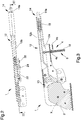
Figure 1 is a side elevation view of a braking device according to the invention, in a first embodiment, with the first and second portion in the home position; -
Figure 2 is a top plan view of the device ofFigure 1 ; -
Figure 3 is a sectional view of the device ofFigure 2 along the track plane III-III; -
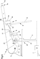
Figures 4 to 6 are side elevation views of the device ofFigure 1 in different operating conditions; -
Figure 7 is a side elevation view of a braking device according to the invention, in a second embodiment. - With particular reference to such illustrations, reference numeral 1 globally indicates a braking device.
- The device 1 comprises a
base body 2, associable with the chassis of a towing vehicle, and at least onecontrol apparatus 10 of the braking of a trailer which is adapted to adjust the pressure of a work fluid along acontrol line 7 connectable to the braking system of the trailer and along anadditional line 11 operatively connected to the automatic and/or parking brake (not shown in the illustrations) of the trailer. In particular, until theadditional line 11 is under pressure the automatic and/or parking brake of the trailer is deactivated, whereas when the pressure along the same drops to zero the automatic and/or parking brake is activated. - The device 1 then comprises first command means 3 associable with the parking brake of a towing vehicle (not shown in the illustrations) and actuatable for the operation of the same and second command means 5 connectable to the
control apparatus 10 and adapted to adjust the pressure along thecontrol line 7. More in detail, the second command means 5 are actuatable to send the work fluid under pressure along thecontrol line 7, through thecontrol apparatus 10, and thus operate the service braking of the trailer. - The device 1 also comprises a
lever 12 which has at least afirst portion 12a hinged to thebody 2, associated with the first command means 3 and movable between a home position, wherein the first command means 3 are deactivated, and at least a braking position, wherein it is rotated with respect to the home position and the first command means 3 are activated. - Conveniently, the
first portion 12a has a plurality of braking positions among which it moves continuously, by applying a gradually increasing force on the first command means 3. - Furthermore, blocking means 13 of the
first portion 12a are also provided in the braking position. More particularly, the blocking means 13 are adapted to maintain thefirst portion 12a in the braking position achieved from time to time and are removable by means of asuitable command 14 to enable the return of the first portion itself to the home position. In the embodiments shown in the illustrations, the blocking means 13 are of the type of a ratchet lever and thecommand 14 is of the type of abutton 14a which counteracts theelastic means 15, e.g. of the type of a spring, for lifting the lever and disengaging it from the teeth of the ratchet. - Advantageously, the first command means 3 are of the mechanical type.
- More in detail, the first command means 3 comprise at least a first flexible and inextensible cable, associated with the
first portion 12a, which is adapted to pull the first cable itself as a result of its rotation from the home position towards the braking position. - As the
first portion 12a rotates away from the braking position, the intensity of the traction force applied on thecable 3 increases. - The
lever 12 also comprises at least asecond portion 12b, graspable by an operator, hinged to thefirst portion 12a, which is associated with the second command means 5 and movable between a home position, wherein the second command means 5 are deactivated, and at least a braking position, wherein it is rotated with respect to the home position and the second command means 5 are activated so as to operate the service braking of the trailer. - Advantageously, the
first portion 12a is hinged to thebody 2 around an axis X of rotation and thesecond portion 12b is in turn hinged to thefirst portion 12a around the same axis X of rotation. Therefore, both the first and thesecond portions - In the embodiment shown in the illustrations, the
second portion 12b is fitted above thefirst portion 12a. In other words, thefirst portion 12a is arranged inside thesecond portion 12b. - Suitably, interconnection means 4 are provided, which are connected to the
second portion 12b, which are adapted to interact with thefirst portion 12a as a result of the operation of thesecond portion 12b, to displace it to the relevant braking position. - As a result of the operation of the
second portion 12b, i.e. its lifting from the home position, both the second portion itself and thefirst portion 12a move to a corresponding braking position by rotating around the axis X. The rotation of thesecond portion 12b around the axis X does in fact involve the exercising of a force on thefirst portion 12a through the interconnection means 4, which causes the rotation thereof around the axis X. This operating condition corresponds to an emergency condition, as a result of which both the parking brake of the towing vehicle and the service braking of the trailer are activated, as shown inFigure 4 . - As a result of the release of the
second portion 12b, the latter returns to the home position, while thefirst portion 12a remains in the braking position taken due to the blocking means 13. This operating condition corresponds to the parking condition, shown inFigure 6 , wherein the parking brake of the towing vehicle is activated and the service braking of the trailer is deactivated. - In the embodiment shown in the illustrations, the second command means 5 are of the mechanical type and comprise at least a second flexible and
inextensible cable 18 associated with thesecond portion 12b, which is adapted to pull thesecond cable 18 as a result of its rotation towards the braking position. In this case too, as thesecond portion 12b rotates around the axis X away from the home position, the pulling force applied on thesecond cable 18 increases. - Advantageously, the interconnection means 4 comprise at least a
first abutment element 4a associated with thesecond cable 18, e.g. of the type of a sheath which covers the second cable itself, and adapted to interact with thefirst portion 12a as a result of the achievement of a first predefined angle of rotation of thesecond portion 12b with respect to thefirst portion 12a. In other words, as a result of the lifting of thesecond portion 12b from the home position, this rotates around the axis X with respect to thefirst portion 12a which, on the other hand, remains in the relative home position. As soon as thesecond portion 12b reaches the above-mentioned first angle of rotation with respect to thefirst portion 12a, thefirst abutment element 4a contacts the first portion itself, so that the further lifting of thesecond portion 12b also causes thefirst portion 12a to displace towards the relative braking position. - Preferably, the interconnection means 4 also comprise at least a
second abutment element 4b associated with thesecond portion 12b and adapted to interact with thefirst portion 12a as a result of the achievement of a second predefined angle of rotation of the second portion itself with respect to thefirst portion 12a, wherein this second angle of rotation has greater width than the first above mentioned angle. This operating condition is shown inFigure 5 . - More in detail, the
second abutment element 4b operates in case of an emergency, for example in the case wherein thesecond cable 18 breaks out, so as to activate the parking braking of the towing vehicle. - The device 1 further comprises third command means 20 operatively connected to the
control apparatus 10 and which are adapted to control the work fluid pressure along theadditional line 11 to manage the state of the automatic and/or parking brake of the trailer. - The third command means 20 can be operated between a normal operating position, in which they maintain the work fluid under pressure along the
additional line 11 to maintain the automatic and/or parking brake of the trailer deactivated, and a parking position, in which they reset the work fluid pressure along theadditional line 11 so as to activate the automatic and/or parking brake itself. - The device 1 then comprises activation means 8 of the third command means 20 operatively connected to the
lever 12 and susceptible to displacing from a first work position, in which they maintain the third command means 20 in the normal operating position, to a second work position, in which they move the third command means 20 to the parking position, as a result of the movement of thefirst portion 12a to the braking position and of thesecond portion 12b to the home position. - According to the invention, the activation means 8 comprise at least one
command lever 22 hinged around afulcrum 24, one supportingelement 23 of the fulcrum 24, the supportingelement 23 being locked together with thefirst portion 12a, where thecommand lever 22 is connected, on opposite sides to thefulcrum 24, to thesecond portion 12b and to the third command means 20. - More in detail, the
command lever 22 is connected to thesecond portion 12b by means of aslot 30 having an elongated shape inside which apin 31 locked together with the second portion is inserted sliding. - Therefore, as a result of the rotation of the
second portion 12b with respect to thefirst portion 12a during its displacement towards the relative braking position, thecommand lever 22 rotates in a first way 32 (counterclockwise in the attached illustrations) with respect to the supportingelement 23 so as to maintain the third command means 20 in the normal operating position. In other words, as a result of the rotation of thecommand lever 22 along thefirst way 32, thepin 31 slides inside therelative slot 30 and the portion connected to the third command means 20 displaces downwards. Thecommand lever 22 instead rotates around thefulcrum 24 along asecond way 33, opposite to thefirst way 32, as a result of the return of thesecond portion 12b to the home position with thefirst portion 12a in the relative braking position due to the blocking means 13, so as to bring the third command means 20 to the parking position. - Advantageously, the third command means 20 are of the mechanical type.
- In particular, in the embodiment shown in the illustrations 1 to 6, the third command means 20 comprise an
inextensible cable 21 associated with thecommand lever 22 on the opposite side of thesecond portion 12b with respect to thefulcrum 24. Thecommand lever 22 is adapted not to pull thethird cable 21 as a result of its rotation in thefirst way 32 and to pull it as a result of its rotation in thesecond way 33. - It follows, therefore, that when the
second portion 12b is moved towards the braking position, as to apply the emergency braking or to keep the towing vehicle stopped to start off on a gradient, thesecond portion 12b moves away from thefirst portion 12a to complete the aforementioned first angle of rotation, as a result of which thefirst abutment element 4a contacts thefirst portion 12a, thecommand lever 22 rotates in thefirst way 32 loosening thethird cable 21. In this operating condition, which corresponds to an emergency condition, the parking brake of the trailer remains inactive. - When the first and
second portions second portion 12b is lowered to return to the home position, the relative movement it makes with respect to thefirst portion 12a causes thecommand lever 22 to rotate in thesecond way 33, so that the portion of thecommand lever 22 with which thethird cable 21 is associated lifts, pulling the third cable itself and activating the parking braking of the trailer. This operating condition corresponds to the parking condition, in which the parking brake of the towing vehicle is activated and the service brake of the trailer is deactivated. - The
command lever 22 is also adapted to pull thethird cable 21, to bring this from the normal operating position to the parking position, as a result of the rotation of the first and of thesecond portion body 2, around the axis X, by a third angle of predefined width. This operating condition, not shown in the illustrations, corresponds in practice to the operating condition in which the level of the emergency braking of the towing vehicle exceeds a predefined value, thereby causing the automatic or parking braking of the trailer to be activated. - In an alternative embodiment, shown in
Figures 7 and 8, the third command means 20 are of the electric type. - Advantageously, the third command means 20 comprise at least an electrical circuit 6, for example connected to a supply source, operatively connected to the
control apparatus 10, which is adapted to enable and prevent the flow of the work fluid along theadditional line 11 as a result of the current flow and cutoff along the electrical circuit 6, respectively. - More in detail, the electric circuit 6 is connected to a solenoid 16 in turn operatively connected to the
control apparatus 10. As a result of the passage of the current along the electric circuit 6 the solenoid 16 activates allowing the passage of the work fluid along theadditional line 11, while when the current passage is interrupted the solenoid 16 goes into the inactive state and thecontrol apparatus 10 placed theadditional line 11 in communication with the exhaust thus causing the activation of the automatic and/or parking brake of the trailer. - The supply source may consist, e.g., of the supply battery of the towing vehicle. In the embodiment of
Figure 7 , the activation means 8 also comprise at least oneactivation element 34 electrically connected to the third command means 20, which is movable between a first and a second work position to bring the third command means themselves to the normal operating position and to the parking position respectively, and is operatively connected to thecommand lever 22. In particular, thecommand lever 22 is adapted to bring theactivation element 34 to the first work position as a result of its rotation along thefirst way 32 and to bring it to the second work position as a result of its rotation along thesecond way 33. - Preferably, the
activation element 34 comprises aswitch 34a, which in normal operating conditions is in the open position, elastic means 35 being provided to push theswitch 34a towards the relative second work position, and alever command 34b kinematically connected to thecommand lever 22 and adapted to interact with theswitch 34a. Thelever command 34b is then moved by thecommand lever 22 during its rotation along thefirst way 32 so as to push theswitch 34a towards the closed position, while it is lifted due to the rotation of thecommand lever 22 along thesecond way 33, thus allowing theswitch 34a to return to the open position. - It has in practice been ascertained that the described invention achieves the intended objects and, in particular, the fact is underlined that the use of mechanical means, such as the command lever described above and claimed, capable of rotating around the relative fulcrum in both ways, makes it possible to easily and practically command the operation of the automatic and/or parking brake of the trailer.
- This mechanism also makes it possible to command, both electrically and mechanically, depending on the option considered most suitable for the specific case, the automatic and/or parking brake of the trailer.
- Furthermore, the fact that the first portion of the lever is hinged to the fixed body of the device around which the second portion of the lever is hinged to the first portion itself makes it considerably easier, with respect to known devices, to manage the command of the parking brake of the towing vehicle and of the service and parking braking of the trailer.
- In particular, the conformation of the lever of the device in question makes it possible to reduce the effort and maneuvering space required by the operator to activate the parking braking of the towing vehicle and the service braking of the trailer.
Claims (12)
- Braking device (1), comprising:- a base body (2) associable with the frame of a towing vehicle;- at least one control apparatus (10) of the braking of a trailer adapted to adjust the pressure of a work fluid along a control line (7) connectable to the braking system of the trailer and along an additional line (11) operatively connectable to the automatic and/or parking brake of the trailer itself;- first command means (3) associable at least with the parking brake of the towing vehicle and actuatable for the operation of the same;- second command means (5) operatively connected to said control apparatus (10) and actuatable to send a work fluid under pressure along said control line (7) and operate the braking of the trailer;- third command means (20) operatively connected to said control apparatus (10) and operable between a normal operating position, in which they maintain the work fluid under pressure along said additional line (11) in order to maintain the automatic and/or parking brake deactivated, and a parking position, in which they reset the pressure of the work fluid along said additional line (11) so as to activate the automatic and/or parking brake;- a lever (12) comprising at least a first portion (12a) hinged to said body (2), associated with said first command means (3) and movable between a home position and at least a braking position in which the first command means themselves are deactivated and activated respectively, there being provided removable blocking means (13) of said first portion (12a) in said braking position, and at least a second portion (12b), graspable by an operator, hinged to said first portion (12a), which is associated with said second command means (5) and movable between a home position and at least a braking position in which said second command means (5) are deactivated and activated, respectively;- activation means (8) of said third command means (20) operatively connected to said lever (12) and adapted to displace from a first work position, in which they maintain said third command means (20) in the normal operating position, to a second work position, in which they bring said third command means (20) to the parking position, as a result of the displacement of said first and of said second portion (12a, 12b) to the relevant braking position and home position respectively;characterized by the fact that said activation means (8) comprise at least one command lever (22) hinged around a fulcrum (24), at least one supporting element (23) of said fulcrum (24) locked together with said first portion (12a), wherein said command lever (22) is connected, on opposite sides of the fulcrum itself, to said second portion (12b) and to said third command means (20) respectively, said command lever (22) rotating in a first way (32) as a result of the relative rotation of said second portion (12b) with respect to said first portion (12a) during the displacement of the second portion itself towards the relative braking position, so as to maintain said third command means (20) in the normal operating position, and rotating in a second way (33) opposite to the previous one, as a result of the return of said second portion (12b) to the home position and with said first portion (12a) in the braking position, so as to bring said third command means (20) to the parking position.
- Device (1) according to claim 1, characterized by the fact that said first portion (12a) is hinged to said body (2) around an axis (X) of rotation and that said second portion (12b) is hinged to said first portion (12a) around said same axis (X) of rotation, there being provided interconnection means (4) which are connected to said second portion (12b) and adapted to interact with said first portion (12a), as a result of the operation of said second portion (12b), to displace it to the relevant braking position, said first and second portion (12a, 12b) rotating around said axis (X), while as a result of the release of said second portion (12b) the latter returns to its home position and said first portion (12a) remains still in the braking position due to said blocking means (13).
- Device (1) according to claim 2, characterized by the fact that said second portion (12b) is fitted above said first portion (12a).
- Device (1) according to one or more of the preceding claims, characterized by the fact that said interconnection means (4) comprise at least a first abutment element (4a) associated with said second cable (18) and adapted to interact with said first portion (12a) as a result of the achievement of a first predefined angle of rotation of said second portion (12b) around said axis (X) with respect to said first portion (12a).
- Device (1) according to claim 4, characterized by the fact that said interconnection means (4) comprise at least a second abutment element (4b) associated with said second portion (12b) and adapted to interact with said first portion (12a) as a result of the achievement of a second predefined angle of rotation around said axis (X) of said second portion (12b) with respect to said first portion (12a), wherein said second angle of rotation has greater width than said first angle of rotation.
- Device (1) according to one or more of the preceding claims, characterized by the fact that said first command means (3) are of the mechanical type and comprise at least a first inextensible cable associated with said first portion (12a), the latter being adapted to pull said first cable as a result of its rotation towards said braking position.
- Device (1) according to one or more of the preceding claims, characterized by the fact that said second command means (5) are of the mechanical type and comprise a second inextensible cable (18) associated with said second portion (12b), the latter being adapted to pull said second cable (18) as a result of its rotation towards said braking position.
- Device (1) according to one or more of the preceding claims, characterized by the fact that said third command means (20) are of the mechanical type and comprise a third inextensible cable (21), said command lever (22) being associated with said third cable (21) and being adapted not to pull and to pull the third cable itself as a result of the rotation along said first way (32) and along said second way (33), respectively.
- Device (1) according to claim 8, characterized by the fact that said command lever (22) is adapted to pull said third cable (21), to bring it from the normal operating position to the parking position, as a result of the rotation of said first and second portion (12a, 12b) around said axis (X) with respect to said body (2) by a third predefined angle of rotation.
- Device (1) according to one or more of claims 1 to 7, characterized by the fact that said third command means (20) are of the electric type.
- Device (1) according to claim 10, characterized by the fact that said activation means (8) comprise at least one activation element (34) electrically connected to said third command means (20) and movable between a first and a second work position in which it brings the third command means themselves in the normal operating position and in the parking position respectively, said command lever (22) being operatively connected to said activation element (34) to bring it to the first work position as a result of the rotation along said first way (32) and to bring it to the second work position as a result of the rotation along said second way (33).
- Device (1) according to claim 11, characterized by the fact that said third command means (20) comprise at least an electrical circuit (6) operatively connected to said control apparatus (10), the latter permitting and preventing the flow of the work fluid along said additional line (11) as a result of the current flow and cutoff along said electrical circuit (6), respectively, and by the fact that said activation element (34) is adapted to close and open said electrical circuit (6) in the first and second work position, respectively.
Applications Claiming Priority (1)
| Application Number | Priority Date | Filing Date | Title |
|---|---|---|---|
| IT102017000051988A IT201700051988A1 (en) | 2017-05-12 | 2017-05-12 | BRAKING DEVICE |
Publications (2)
| Publication Number | Publication Date |
|---|---|
| EP3401170A1 true EP3401170A1 (en) | 2018-11-14 |
| EP3401170B1 EP3401170B1 (en) | 2019-12-11 |
Family
ID=60020344
Family Applications (1)
| Application Number | Title | Priority Date | Filing Date |
|---|---|---|---|
| EP18171889.1A Active EP3401170B1 (en) | 2017-05-12 | 2018-05-11 | Braking device |
Country Status (2)
| Country | Link |
|---|---|
| EP (1) | EP3401170B1 (en) |
| IT (1) | IT201700051988A1 (en) |
Citations (4)
| Publication number | Priority date | Publication date | Assignee | Title |
|---|---|---|---|---|
| FR2075876A1 (en) * | 1969-11-27 | 1971-10-15 | Schroter Hans | |
| FR2401811A1 (en) * | 1977-09-01 | 1979-03-30 | Automotive Prod Co Ltd | Servo control for trailer brakes - has direct operation from master cylinder with control pressure inversely proportional to servo pressure to allow fine control |
| EP2962912A2 (en) * | 2014-07-02 | 2016-01-06 | Safim S.p.A. | Braking device |
| WO2016185327A1 (en) * | 2015-05-15 | 2016-11-24 | Safim S.P.A. | Braking device |
-
2017
- 2017-05-12 IT IT102017000051988A patent/IT201700051988A1/en unknown
-
2018
- 2018-05-11 EP EP18171889.1A patent/EP3401170B1/en active Active
Patent Citations (4)
| Publication number | Priority date | Publication date | Assignee | Title |
|---|---|---|---|---|
| FR2075876A1 (en) * | 1969-11-27 | 1971-10-15 | Schroter Hans | |
| FR2401811A1 (en) * | 1977-09-01 | 1979-03-30 | Automotive Prod Co Ltd | Servo control for trailer brakes - has direct operation from master cylinder with control pressure inversely proportional to servo pressure to allow fine control |
| EP2962912A2 (en) * | 2014-07-02 | 2016-01-06 | Safim S.p.A. | Braking device |
| WO2016185327A1 (en) * | 2015-05-15 | 2016-11-24 | Safim S.P.A. | Braking device |
Also Published As
| Publication number | Publication date |
|---|---|
| IT201700051988A1 (en) | 2018-11-12 |
| EP3401170B1 (en) | 2019-12-11 |
Similar Documents
| Publication | Publication Date | Title |
|---|---|---|
| CN110606067B (en) | Emergency braking method for an aircraft | |
| EP2310239B1 (en) | Brake assembly for a vehicle | |
| MXPA01009330A (en) | Control apparatus for the application and release of the hand brake of a railway vehicle. | |
| AU2020201936B2 (en) | Locomotive parking brake | |
| EP3294596B1 (en) | Braking device | |
| BRPI1009172B1 (en) | automatic release manual brake control system | |
| EP1914136B1 (en) | Parking brake, particularly for a farm tractor, with a safety device | |
| EP2962912B1 (en) | Braking device | |
| EP3401170B1 (en) | Braking device | |
| EP3148851B1 (en) | Actuator device for a combined rear-front brake system of a motor vehicle, combined rear-front brake system of a motor vehicle and motor vehicle thereof | |
| EP3000631A1 (en) | Device for the towing vehicle-trailer connection | |
| EP1922233B1 (en) | Braking system | |
| EP3225473A1 (en) | Device for the control of the braking of a trailer | |
| GB2290366A (en) | Apparatus for jointly actuating a pair of valves | |
| EP3299229B1 (en) | An automatic parking brake | |
| CN106133373B (en) | clutch operating device | |
| US4265492A (en) | Braking apparatus for vehicles | |
| EP2952398B1 (en) | Valve assembly | |
| CN210391100U (en) | Parking control mechanism and system and electric vehicle thereof | |
| EP2921357B1 (en) | Parking brake system and method for operating a parking brake system | |
| EP3085589B1 (en) | Valve assembly | |
| JPS625822B2 (en) | ||
| EP3722166A1 (en) | Braking circuit for the braking of a vehicle | |
| EP4574596A1 (en) | Device for controlling the braking of a trailer | |
| EP3669623B1 (en) | Towing device for an agricultural or industrial vehicle |
Legal Events
| Date | Code | Title | Description |
|---|---|---|---|
| PUAI | Public reference made under article 153(3) epc to a published international application that has entered the european phase |
Free format text: ORIGINAL CODE: 0009012 |
|
| STAA | Information on the status of an ep patent application or granted ep patent |
Free format text: STATUS: THE APPLICATION HAS BEEN PUBLISHED |
|
| AK | Designated contracting states |
Kind code of ref document: A1 Designated state(s): AL AT BE BG CH CY CZ DE DK EE ES FI FR GB GR HR HU IE IS IT LI LT LU LV MC MK MT NL NO PL PT RO RS SE SI SK SM TR |
|
| AX | Request for extension of the european patent |
Extension state: BA ME |
|
| STAA | Information on the status of an ep patent application or granted ep patent |
Free format text: STATUS: REQUEST FOR EXAMINATION WAS MADE |
|
| 17P | Request for examination filed |
Effective date: 20190513 |
|
| RBV | Designated contracting states (corrected) |
Designated state(s): AL AT BE BG CH CY CZ DE DK EE ES FI FR GB GR HR HU IE IS IT LI LT LU LV MC MK MT NL NO PL PT RO RS SE SI SK SM TR |
|
| GRAP | Despatch of communication of intention to grant a patent |
Free format text: ORIGINAL CODE: EPIDOSNIGR1 |
|
| STAA | Information on the status of an ep patent application or granted ep patent |
Free format text: STATUS: GRANT OF PATENT IS INTENDED |
|
| RIC1 | Information provided on ipc code assigned before grant |
Ipc: B60T 7/10 20060101AFI20190607BHEP |
|
| INTG | Intention to grant announced |
Effective date: 20190703 |
|
| GRAS | Grant fee paid |
Free format text: ORIGINAL CODE: EPIDOSNIGR3 |
|
| GRAA | (expected) grant |
Free format text: ORIGINAL CODE: 0009210 |
|
| STAA | Information on the status of an ep patent application or granted ep patent |
Free format text: STATUS: THE PATENT HAS BEEN GRANTED |
|
| AK | Designated contracting states |
Kind code of ref document: B1 Designated state(s): AL AT BE BG CH CY CZ DE DK EE ES FI FR GB GR HR HU IE IS IT LI LT LU LV MC MK MT NL NO PL PT RO RS SE SI SK SM TR |
|
| REG | Reference to a national code |
Ref country code: GB Ref legal event code: FG4D |
|
| REG | Reference to a national code |
Ref country code: CH Ref legal event code: EP |
|
| REG | Reference to a national code |
Ref country code: AT Ref legal event code: REF Ref document number: 1211890 Country of ref document: AT Kind code of ref document: T Effective date: 20191215 |
|
| REG | Reference to a national code |
Ref country code: DE Ref legal event code: R096 Ref document number: 602018001549 Country of ref document: DE |
|
| REG | Reference to a national code |
Ref country code: IE Ref legal event code: FG4D |
|
| REG | Reference to a national code |
Ref country code: NL Ref legal event code: MP Effective date: 20191211 |
|
| REG | Reference to a national code |
Ref country code: LT Ref legal event code: MG4D |
|
| PG25 | Lapsed in a contracting state [announced via postgrant information from national office to epo] |
Ref country code: BG Free format text: LAPSE BECAUSE OF FAILURE TO SUBMIT A TRANSLATION OF THE DESCRIPTION OR TO PAY THE FEE WITHIN THE PRESCRIBED TIME-LIMIT Effective date: 20200311 Ref country code: FI Free format text: LAPSE BECAUSE OF FAILURE TO SUBMIT A TRANSLATION OF THE DESCRIPTION OR TO PAY THE FEE WITHIN THE PRESCRIBED TIME-LIMIT Effective date: 20191211 Ref country code: NO Free format text: LAPSE BECAUSE OF FAILURE TO SUBMIT A TRANSLATION OF THE DESCRIPTION OR TO PAY THE FEE WITHIN THE PRESCRIBED TIME-LIMIT Effective date: 20200311 Ref country code: GR Free format text: LAPSE BECAUSE OF FAILURE TO SUBMIT A TRANSLATION OF THE DESCRIPTION OR TO PAY THE FEE WITHIN THE PRESCRIBED TIME-LIMIT Effective date: 20200312 Ref country code: SE Free format text: LAPSE BECAUSE OF FAILURE TO SUBMIT A TRANSLATION OF THE DESCRIPTION OR TO PAY THE FEE WITHIN THE PRESCRIBED TIME-LIMIT Effective date: 20191211 Ref country code: LV Free format text: LAPSE BECAUSE OF FAILURE TO SUBMIT A TRANSLATION OF THE DESCRIPTION OR TO PAY THE FEE WITHIN THE PRESCRIBED TIME-LIMIT Effective date: 20191211 Ref country code: LT Free format text: LAPSE BECAUSE OF FAILURE TO SUBMIT A TRANSLATION OF THE DESCRIPTION OR TO PAY THE FEE WITHIN THE PRESCRIBED TIME-LIMIT Effective date: 20191211 |
|
| PG25 | Lapsed in a contracting state [announced via postgrant information from national office to epo] |
Ref country code: HR Free format text: LAPSE BECAUSE OF FAILURE TO SUBMIT A TRANSLATION OF THE DESCRIPTION OR TO PAY THE FEE WITHIN THE PRESCRIBED TIME-LIMIT Effective date: 20191211 Ref country code: RS Free format text: LAPSE BECAUSE OF FAILURE TO SUBMIT A TRANSLATION OF THE DESCRIPTION OR TO PAY THE FEE WITHIN THE PRESCRIBED TIME-LIMIT Effective date: 20191211 |
|
| PG25 | Lapsed in a contracting state [announced via postgrant information from national office to epo] |
Ref country code: AL Free format text: LAPSE BECAUSE OF FAILURE TO SUBMIT A TRANSLATION OF THE DESCRIPTION OR TO PAY THE FEE WITHIN THE PRESCRIBED TIME-LIMIT Effective date: 20191211 |
|
| PG25 | Lapsed in a contracting state [announced via postgrant information from national office to epo] |
Ref country code: ES Free format text: LAPSE BECAUSE OF FAILURE TO SUBMIT A TRANSLATION OF THE DESCRIPTION OR TO PAY THE FEE WITHIN THE PRESCRIBED TIME-LIMIT Effective date: 20191211 Ref country code: EE Free format text: LAPSE BECAUSE OF FAILURE TO SUBMIT A TRANSLATION OF THE DESCRIPTION OR TO PAY THE FEE WITHIN THE PRESCRIBED TIME-LIMIT Effective date: 20191211 Ref country code: NL Free format text: LAPSE BECAUSE OF FAILURE TO SUBMIT A TRANSLATION OF THE DESCRIPTION OR TO PAY THE FEE WITHIN THE PRESCRIBED TIME-LIMIT Effective date: 20191211 Ref country code: CZ Free format text: LAPSE BECAUSE OF FAILURE TO SUBMIT A TRANSLATION OF THE DESCRIPTION OR TO PAY THE FEE WITHIN THE PRESCRIBED TIME-LIMIT Effective date: 20191211 Ref country code: RO Free format text: LAPSE BECAUSE OF FAILURE TO SUBMIT A TRANSLATION OF THE DESCRIPTION OR TO PAY THE FEE WITHIN THE PRESCRIBED TIME-LIMIT Effective date: 20191211 Ref country code: PT Free format text: LAPSE BECAUSE OF FAILURE TO SUBMIT A TRANSLATION OF THE DESCRIPTION OR TO PAY THE FEE WITHIN THE PRESCRIBED TIME-LIMIT Effective date: 20200506 |
|
| PG25 | Lapsed in a contracting state [announced via postgrant information from national office to epo] |
Ref country code: SM Free format text: LAPSE BECAUSE OF FAILURE TO SUBMIT A TRANSLATION OF THE DESCRIPTION OR TO PAY THE FEE WITHIN THE PRESCRIBED TIME-LIMIT Effective date: 20191211 Ref country code: SK Free format text: LAPSE BECAUSE OF FAILURE TO SUBMIT A TRANSLATION OF THE DESCRIPTION OR TO PAY THE FEE WITHIN THE PRESCRIBED TIME-LIMIT Effective date: 20191211 Ref country code: IS Free format text: LAPSE BECAUSE OF FAILURE TO SUBMIT A TRANSLATION OF THE DESCRIPTION OR TO PAY THE FEE WITHIN THE PRESCRIBED TIME-LIMIT Effective date: 20200411 |
|
| REG | Reference to a national code |
Ref country code: DE Ref legal event code: R097 Ref document number: 602018001549 Country of ref document: DE |
|
| REG | Reference to a national code |
Ref country code: AT Ref legal event code: MK05 Ref document number: 1211890 Country of ref document: AT Kind code of ref document: T Effective date: 20191211 |
|
| PLBE | No opposition filed within time limit |
Free format text: ORIGINAL CODE: 0009261 |
|
| STAA | Information on the status of an ep patent application or granted ep patent |
Free format text: STATUS: NO OPPOSITION FILED WITHIN TIME LIMIT |
|
| PG25 | Lapsed in a contracting state [announced via postgrant information from national office to epo] |
Ref country code: DK Free format text: LAPSE BECAUSE OF FAILURE TO SUBMIT A TRANSLATION OF THE DESCRIPTION OR TO PAY THE FEE WITHIN THE PRESCRIBED TIME-LIMIT Effective date: 20191211 |
|
| 26N | No opposition filed |
Effective date: 20200914 |
|
| PG25 | Lapsed in a contracting state [announced via postgrant information from national office to epo] |
Ref country code: AT Free format text: LAPSE BECAUSE OF FAILURE TO SUBMIT A TRANSLATION OF THE DESCRIPTION OR TO PAY THE FEE WITHIN THE PRESCRIBED TIME-LIMIT Effective date: 20191211 Ref country code: SI Free format text: LAPSE BECAUSE OF FAILURE TO SUBMIT A TRANSLATION OF THE DESCRIPTION OR TO PAY THE FEE WITHIN THE PRESCRIBED TIME-LIMIT Effective date: 20191211 |
|
| REG | Reference to a national code |
Ref country code: DE Ref legal event code: R119 Ref document number: 602018001549 Country of ref document: DE |
|
| PG25 | Lapsed in a contracting state [announced via postgrant information from national office to epo] |
Ref country code: MC Free format text: LAPSE BECAUSE OF FAILURE TO SUBMIT A TRANSLATION OF THE DESCRIPTION OR TO PAY THE FEE WITHIN THE PRESCRIBED TIME-LIMIT Effective date: 20191211 |
|
| PG25 | Lapsed in a contracting state [announced via postgrant information from national office to epo] |
Ref country code: PL Free format text: LAPSE BECAUSE OF FAILURE TO SUBMIT A TRANSLATION OF THE DESCRIPTION OR TO PAY THE FEE WITHIN THE PRESCRIBED TIME-LIMIT Effective date: 20191211 |
|
| REG | Reference to a national code |
Ref country code: BE Ref legal event code: MM Effective date: 20200531 |
|
| PG25 | Lapsed in a contracting state [announced via postgrant information from national office to epo] |
Ref country code: LU Free format text: LAPSE BECAUSE OF NON-PAYMENT OF DUE FEES Effective date: 20200511 |
|
| PG25 | Lapsed in a contracting state [announced via postgrant information from national office to epo] |
Ref country code: FR Free format text: LAPSE BECAUSE OF NON-PAYMENT OF DUE FEES Effective date: 20200531 Ref country code: IE Free format text: LAPSE BECAUSE OF NON-PAYMENT OF DUE FEES Effective date: 20200511 |
|
| PG25 | Lapsed in a contracting state [announced via postgrant information from national office to epo] |
Ref country code: DE Free format text: LAPSE BECAUSE OF NON-PAYMENT OF DUE FEES Effective date: 20201201 Ref country code: BE Free format text: LAPSE BECAUSE OF NON-PAYMENT OF DUE FEES Effective date: 20200531 |
|
| REG | Reference to a national code |
Ref country code: CH Ref legal event code: PL |
|
| PG25 | Lapsed in a contracting state [announced via postgrant information from national office to epo] |
Ref country code: CH Free format text: LAPSE BECAUSE OF NON-PAYMENT OF DUE FEES Effective date: 20210531 Ref country code: LI Free format text: LAPSE BECAUSE OF NON-PAYMENT OF DUE FEES Effective date: 20210531 |
|
| PG25 | Lapsed in a contracting state [announced via postgrant information from national office to epo] |
Ref country code: TR Free format text: LAPSE BECAUSE OF FAILURE TO SUBMIT A TRANSLATION OF THE DESCRIPTION OR TO PAY THE FEE WITHIN THE PRESCRIBED TIME-LIMIT Effective date: 20191211 Ref country code: MT Free format text: LAPSE BECAUSE OF FAILURE TO SUBMIT A TRANSLATION OF THE DESCRIPTION OR TO PAY THE FEE WITHIN THE PRESCRIBED TIME-LIMIT Effective date: 20191211 Ref country code: CY Free format text: LAPSE BECAUSE OF FAILURE TO SUBMIT A TRANSLATION OF THE DESCRIPTION OR TO PAY THE FEE WITHIN THE PRESCRIBED TIME-LIMIT Effective date: 20191211 |
|
| PG25 | Lapsed in a contracting state [announced via postgrant information from national office to epo] |
Ref country code: MK Free format text: LAPSE BECAUSE OF FAILURE TO SUBMIT A TRANSLATION OF THE DESCRIPTION OR TO PAY THE FEE WITHIN THE PRESCRIBED TIME-LIMIT Effective date: 20191211 |
|
| GBPC | Gb: european patent ceased through non-payment of renewal fee |
Effective date: 20220511 |
|
| PG25 | Lapsed in a contracting state [announced via postgrant information from national office to epo] |
Ref country code: GB Free format text: LAPSE BECAUSE OF NON-PAYMENT OF DUE FEES Effective date: 20220511 |
|
| P01 | Opt-out of the competence of the unified patent court (upc) registered |
Effective date: 20230527 |
|
| PGFP | Annual fee paid to national office [announced via postgrant information from national office to epo] |
Ref country code: IT Payment date: 20250520 Year of fee payment: 8 |