EP3401125A1 - Run strip profile of a vehicle tyre - Google Patents
Run strip profile of a vehicle tyre Download PDFInfo
- Publication number
- EP3401125A1 EP3401125A1 EP18157339.5A EP18157339A EP3401125A1 EP 3401125 A1 EP3401125 A1 EP 3401125A1 EP 18157339 A EP18157339 A EP 18157339A EP 3401125 A1 EP3401125 A1 EP 3401125A1
- Authority
- EP
- European Patent Office
- Prior art keywords
- extension
- extension portion
- sipe
- circumferential
- sipes
- Prior art date
- Legal status (The legal status is an assumption and is not a legal conclusion. Google has not performed a legal analysis and makes no representation as to the accuracy of the status listed.)
- Granted
Links
- 230000002093 peripheral effect Effects 0.000 claims description 6
- 230000007704 transition Effects 0.000 claims description 6
- 239000004606 Fillers/Extenders Substances 0.000 claims 3
- 230000015572 biosynthetic process Effects 0.000 description 18
- 101100334009 Caenorhabditis elegans rib-2 gene Proteins 0.000 description 6
- 230000005540 biological transmission Effects 0.000 description 5
- XLYOFNOQVPJJNP-UHFFFAOYSA-N water Substances O XLYOFNOQVPJJNP-UHFFFAOYSA-N 0.000 description 4
- 230000005284 excitation Effects 0.000 description 2
- 238000005096 rolling process Methods 0.000 description 2
- 238000005299 abrasion Methods 0.000 description 1
- 238000006243 chemical reaction Methods 0.000 description 1
- 230000000694 effects Effects 0.000 description 1
- 238000003780 insertion Methods 0.000 description 1
- 230000037431 insertion Effects 0.000 description 1
- 238000004513 sizing Methods 0.000 description 1
Images

Classifications
-
- B—PERFORMING OPERATIONS; TRANSPORTING
- B60—VEHICLES IN GENERAL
- B60C—VEHICLE TYRES; TYRE INFLATION; TYRE CHANGING; CONNECTING VALVES TO INFLATABLE ELASTIC BODIES IN GENERAL; DEVICES OR ARRANGEMENTS RELATED TO TYRES
- B60C11/00—Tyre tread bands; Tread patterns; Anti-skid inserts
- B60C11/03—Tread patterns
- B60C11/12—Tread patterns characterised by the use of narrow slits or incisions, e.g. sipes
- B60C11/1236—Tread patterns characterised by the use of narrow slits or incisions, e.g. sipes with special arrangements in the tread pattern
- B60C11/125—Tread patterns characterised by the use of narrow slits or incisions, e.g. sipes with special arrangements in the tread pattern arranged at the groove bottom
-
- B—PERFORMING OPERATIONS; TRANSPORTING
- B60—VEHICLES IN GENERAL
- B60C—VEHICLE TYRES; TYRE INFLATION; TYRE CHANGING; CONNECTING VALVES TO INFLATABLE ELASTIC BODIES IN GENERAL; DEVICES OR ARRANGEMENTS RELATED TO TYRES
- B60C11/00—Tyre tread bands; Tread patterns; Anti-skid inserts
- B60C11/03—Tread patterns
- B60C11/0304—Asymmetric patterns
-
- B—PERFORMING OPERATIONS; TRANSPORTING
- B60—VEHICLES IN GENERAL
- B60C—VEHICLE TYRES; TYRE INFLATION; TYRE CHANGING; CONNECTING VALVES TO INFLATABLE ELASTIC BODIES IN GENERAL; DEVICES OR ARRANGEMENTS RELATED TO TYRES
- B60C11/00—Tyre tread bands; Tread patterns; Anti-skid inserts
- B60C11/03—Tread patterns
- B60C11/0306—Patterns comprising block rows or discontinuous ribs
- B60C11/0309—Patterns comprising block rows or discontinuous ribs further characterised by the groove cross-section
Definitions
- the invention relates to a tread pattern of a vehicle tire - in particular a car vehicle tire - with separate by circumferential grooves profile strips and formed in profile bands sipes, with a profile band, in which sipes with a first extension portion with the largest directional component of the extension in the circumferential direction U and a second Extension section with the largest directional component in the axial direction A, which opens into a circumferential groove are formed, wherein first sipes whose second extension section opens into a circumferential groove bounding the profile band, and second sipes are formed, the second extension section opens into another circumferential groove bounding the profile band ,
- tread ribs in the central region of a tread pattern of a passenger vehicle tire with fine incisions, which are usually aligned at an oblique angle of 45 degrees to the circumferential direction. This makes it possible to achieve a compromise in noise excitation, abrasion properties and shape complexity.
- such a design is at the expense of wet braking properties, since the sipes then hardly provide edges for transmitting the braking forces available.
- From the DE 10 2012 108 384 A1 is a tread pattern of a pneumatic vehicle tire with peripheral grooves separated by circumferential grooves known in which in a circumferential rib sipes with a first extension portion in which the sipe extends completely in the circumferential direction and with a second extension portion, in which the sipe is oriented obliquely to the circumferential groove and thereby has a larger directional component in the axial direction than in the circumferential direction.
- the substantially axial extension portion opens into the one circumferential groove and second sipes whose substantially axial extension portion opens into the other circumferential groove.
- the first and second sipes are arranged in the circumferential rib in succession so that their circumferentially extending first extension portions are each arranged in the same axial position in the circumferential rib and are thus arranged on a line extending over the circumference of the vehicle pneumatic tire behind the other.
- the training allows with their aligned in the pure circumferential direction first extension portions of the sipes a recording of the water and a derivative by the transverse second extension portions in the adjacent circumferential grooves and due to the pure circumferential orientation of the first extension portion and the oblique orientation of the second extension portion of each of the sipes a Reduction of noise.
- the handling is further improved and thereby favors by the extension portions of the sipes with substantially axial direction component wet brakes ,
- the invention has for its object to enable in such a vehicle tire with profiled strip and sipes reduced noise with good wet handling and wet braking properties.
- the object is achieved by the formation of a tread pattern of a vehicle tire - in particular a vehicle tire - separated by circumferential grooves profile bands and formed in profile bands fine incisions, with a profile band, in which sipes with a first extension portion with the largest directional component of the extension in the circumferential direction U and formed with a second extension portion with the largest directional component in the axial direction A, which opens into a circumferential groove, wherein first sipes whose second extension portion opens into a circumferential groove bounding the profile band, and second sipes are formed, the second extension portion in another the Profile band bounding circumferential groove opens, solved according to the features of claim 1, in which over the circumference of the profile strip away from each pair of axially juxtaposed first n and second sipes are formed, the first extension portion are aligned parallel to each other and positioned in their circumferential extent with overlap to each other, wherein the second extension portions of the two sipes axially spaced from each other are positioned, and in which
- This design makes it possible, in such a pneumatic vehicle tire in a profile band by the pairwise formation of sipes a high number of substantially circumferentially oriented sipe sections and thus an increased number of grip edges for the transmission of shear forces and thereby an increased number of extension sections of sipes with larger axial extension direction component to provide for transmission of circumferentially directed forces.
- a high number of grip edges can be provided in a simple manner for better wet grip as well as for achieving improved wet handling behavior.
- the pairwise arrangement of the sipes with axial spacing of their second extension sections relative to one another and with their first extension sections aligned in parallel makes it possible to ensure a stiff core region of the profile strip over the circumference of the tire, whereby good dry and wet handling properties can be further improved.
- the formation of the sipes with their large extension portions in the circumferential direction further promotes the achievement of a low noise level.
- the formation of one of the two sipes with a chamfer, which extends to the circumferential groove, thereby favors despite high grip edge number of the paired arrangement of sipes ensuring the formation of noise at a very low level.
- the paired arrangement and the chamfer also favor a reliable good drainage from the area of the profile band to the circumferential groove.
- a vehicle tire according to the features of claim 5, wherein the sipe has a kink in the course at which the first extension portion adjacent to the second extension portion, and wherein the chamfered region in a profile band from the circumferential groove on the second extension portion of the sipe, is extended over the kink point into the first extension portion of the sipe and - in particular at a distance from the direction away from the kink point extending end of the first extension portion - ends.
- the water drainage effect can be implemented by the bevel in the circumferential groove particularly effective.
- This allows for an optimal compromise for achieving additionally good dry handling properties. This is particularly effective when using axially outer profile bands of the vehicle tire.
- a vehicle tire according to the features of claim 7, wherein the second extension portion aligned in its extension course including an inclination angle ⁇ with 0 ° ⁇ 30 ° - in particular with 0 ° ⁇ 20 ° - to the axial direction A. is, and wherein in particular the first extension portion is aligned in its extension course, including an inclination angle ⁇ with 0 ° ⁇ 15 ° to the circumferential direction U.
- a vehicle tire according to the features of claim 8, wherein in a profile band, the two sipes of a pair in their extension direction, starting from the respective circumferential groove over the second extension portion and the first extension portion to the direction away from the second extension portion extension end of the first extension portion and thus of the fine incision are aligned with mutually opposite orientation of the circumferential extent.
- a vehicle tire according to the features of claim 9, wherein in a profile band, the two sipes of a pair in their extension direction, starting from the respective circumferential groove over the second extension portion and the first extension portion to the direction away from the second extension portion extension end of the first extension portion and thus of the sipe are aligned with the same orientation of the circumferential extent.
- a vehicle tire according to the features of claim 10, wherein the one fine incision of a pair with a measured in the circumferential direction U greater overall length L 1 than the other sipe is formed, each of which in the circumferential direction U, starting from the junction of the second extension portion of the respective sipe in the circumferential groove over the second extension portion and the first extension portion up to the second end portion pointing away extension end of the first extension portion and thus of the sipe indicated length, wherein in the longer sipe the total extension length L 1 and measured in the circumferential direction U extension length L 2 of the first extension portion are formed with 15mm ⁇ L 1 ⁇ 30mm and 0.6L 1 ⁇ L 2 ⁇ L 1 . This allows optimal implementation within the pitch lengths of conventional car tires.
- the shorter sipe of the pair is formed with a measured in the circumferential direction U total length of extension L 3, wherein in the shorter sipe, the total length of extension L 3 and measured in the peripheral direction U extending length L 4 of the first extension portion are formed with (1/3) L 1 ⁇ L 3 ⁇ L 1 and 0.6L 3 ⁇ L 4 ⁇ L 3 .
- This allows in a simple manner good conversions to achieve very good wet handling properties and wet braking properties with very low noise and good dry handling properties.
- a vehicle tire according to the features of claim 12 wherein the shorter sipe of the pair in the axial direction A respectively on the outside of the vehicle (OU) indicative side of the profile strip of the tire and the longer to the vehicle inner side (IN) indicative side of the profile strip of the tire is positioned.
- the side of the profiled strip which points to the vehicle outer side (OU) and which is important for dry handling properties is formed in a simple manner with increased transverse rigidity and thus with greater stability for dry handling, whereby the dry handling properties can be further improved.
- the circumferential rigidity of the profiled strip can be reduced in a simple manner, especially in the second section of the sipe which substantially influences the circumferential rigidity, which promotes low rolling resistance and wet-setting properties, such as wet brakes.
- a vehicle tire according to the features of claim 14 wherein the sipes of a pair with their first extension portion at a distance a with 2mm ⁇ a ⁇ 10mm - in particular with 5mm ⁇ a ⁇ 8mm - are formed to each other.
- the formation of the pairs to achieve good wet handling properties and wet braking properties can be implemented with very low noise in a particularly simple manner with sufficiently high stability of the profile band.
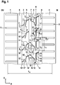
- Fig.1 shows a tread pattern of a pneumatic vehicle tire of a passenger car (passenger car), in which a plurality of circumferentially extending over the entire circumference of the pneumatic vehicle tire circumferential ribs 1, 2, 3 and 4 in the axial direction A of the pneumatic vehicle tire are arranged side by side.
- the circumferential ribs 1 and 2 are separated from each other in the axial direction A by a circumferential groove 6, which extends over the entire circumference of the vehicle pneumatic tire and is aligned in the circumferential direction U.
- the circumferential ribs 2 and 3 are separated from one another in the axial direction A of the pneumatic vehicle tire by a circumferential groove 7 which extends over the entire circumference of the vehicle pneumatic tire and is aligned in the circumferential direction U.
- the circumferential ribs 3 and 4 are separated from one another in the axial direction A by a circumferential groove 8 which extends over the entire circumference of the pneumatic vehicle tire and is aligned in the circumferential direction U.
- the circumferential ribs 1 and 4 are each formed as formed in a tire shoulder shoulder ribs. In this case, the circumferential rib 1 is formed in the shoulder facing the vehicle outside the vehicle OU and the circumferential rib 4 is formed in the shoulder facing the vehicle inside IN in the vehicle.
- the circumferential ribs 2 and 3 are formed between the shoulder ribs formed as circumferential ribs 1 and 4 as the central circumferential ribs. As in Fig.1 is illustrated, the ground contact width T A of the pneumatic vehicle tire extends from an axial extension region within the circumferential rib 1 to a position in the axial extension region of the circumferential rib 4.
- transverse grooves 5 of known type are formed, which, starting from the adjacent to the respective circumferential rib 1 and 4 circumferential groove 6 and 8 in the axial direction A to the axial extension area outside the ground contact width T A extends and ends there.
- profile block rows of known type are formed in the region of the tire shoulder.
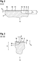
- the circumferential rib 3 As in the FIGS. 2 to 6 is illustrated by the circumferential rib 3, the circumferential ribs 1, 2, 3 and 4 in the radial direction R outwardly by a in the extension region of the ground contact width T A forming the ground contact surface, radially outer surface 19 is limited.
- sipes 10 and 11 are formed.
- the sipes 10 are formed from a second extension section 13 extending from the circumferential groove 7 to a kink 17 and from a first extension section 12 connected to the second extension section 13 in a kinked position 17.
- the fine incisions 11 are formed from a second extension section 15 extending from the circumferential groove 8 to a kink 16 and from a first extension section 14 connected to the second extension section 15 at the kinking point.
- the first extension section 14 of the sipe 11 extends between kink 16 to a direction away from the respective kink 16 extension end of the fine incision 11.
- the first extension portion 12 of the sipe 10 extends between kink 17 to a direction away from the respective kink 17 extension end of the sipe 10.
- the sipes 11 and 10 of a pair are in their respective first extension portion 14 and 12 of the sipe 10 each along its extension between kink 16 and 17 and the direction away from the respective kink 16 and 17 extension end including an inclination angle ⁇ 0 ° ⁇ 15 ° to the circumferential direction U aligned in a straight line parallel to each other.
- ⁇ 0 ° is selected.
- the sipe 11 Starting from the kink 16 of the sipe 11 is with its second extension portion 15, including a Inclination angle ⁇ to the axial direction A extending extends and extends to the circumferential groove 8, in which it opens.
- the sipe 10 is formed inclined starting from the kink 17 with its second extension portion 13 with the inclusion of an inclination angle ⁇ to the axial direction and extends to the circumferential groove 7, in which it opens.
- the sipe 11 along its entire extent, starting from the kinking point 16 pioneering extension end of the first extension portion 14 along its extension in the first extension portion 14, over the kink 16 and the second extension portion 15 away until its confluence with the circumferential groove. 8 formed with a constant circumferential orientation.
- the sipe 10 along its entire extension, starting from the extension of the first extension portion 12 pointing away from the kink point 17 along its extent in the first extension portion 12, over the kink 17 and the second extension portion 13 to its confluence with the circumferential groove 7 with the same permanent circumferential orientation formed.
- the circumferential orientation starting from the first extension section 12 via the second extension section 13 of the sipe 10 corresponds to the circumferential orientation of the sipe 11 starting from the first extension section 14 via the second extension section 15.
- the sipe 11 is with its first extension section 14 from the first extension section 12 of the sipe 10th positioned at a distance a from each other.
- the second extension portion 13 of the sipe 10 from the second extension portion 15 of the sipe 11 in the axial direction A are arranged without overlapping and spaced from each other.
- the fine incision 11 is measured from its junction in the circumferential groove 8 to its other extension end with a measured in the circumferential direction U of the vehicle pneumatic tire total length L 1 and with a kinked 16 and pointing away from the kink 16 extension end of the first extension portions 14 in the circumferential direction U Extension length L 2 of the first extension portion 14 is formed.
- the sipe 10 is measured with an extension length L 3 measured circumferentially from its junction in the circumferential groove 7 to its other extent end, and with a circumferential end U of the first extension portion 12 between kink 17 and the extension end 17 of the kink 17 Extension length L 4 of the first extension portion 12 is formed.
- the extension length L 1 of the sipe 11 is chosen to be greater than the extension length L 3 of the sipe 10.
- L 1 is formed with 15 mm ⁇ L 1 ⁇ 30 mm and L 2 with 0.6 L 1 ⁇ L 2 ⁇ L 1 .
- the extension lengths L 3 and L 4 are formed with (1/3) L 1 ⁇ L 3 ⁇ L 1 and (0.6 L 3 ) ⁇ L 4 ⁇ L 3 .
- L 3 is selected smaller than L 1 .
- the transition between the first extension section 14 and the second extension section 15 or between the first extension section 12 and the second extension section 13 is provided in each case rounded with a radius of curvature.
- the extension length L 4 or L 2 is measured in each case between the intersection of the rectilinear extension of the first extension portion 14 and 12 with the second extension portion 15 and 13 of the respective fine incision 10 or 11 and the extension end of the respective first extension section 14 or 12 of the corresponding sipe 10 or 11.
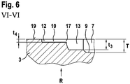
- the sipe 11 is formed along its extension between the circumferential groove 8 and kink 16 with a measured between the radially outer surface 19 and the sipe 11 radially inwardly delimiting Feininroughstress depth t 1 and along its extent in the first extension portion 14 between the Kink point 16 and the direction away from the kink point extension end of the first sipe 14 with a depth t 2 with t 2 ⁇ t 1 ⁇ T, where T indicates the depth of the circumferential groove 8.
- the sipe 10 is along its extension in the second extension portion 13 between the circumferential groove 7 and kink 17 with a depth t 3 and in its first extension portion 12 between kink 17 and the direction away from the kink point 17 extension end of the first extension portion 12 with a depth t 4 formed with t 4 ⁇ t 3 ⁇ T, where T indicates the depth of the circumferential grooves 7 and 8.
- the depths are 6mm ⁇ T ⁇ 8mm, 0.8T ⁇ t 1 ⁇ T, 0.1T ⁇ t 2 ⁇ 0.3T, 0.8T ⁇ t 3 ⁇ T and 0.1T ⁇ t 4 ⁇ 0.3T educated.
- T 7.5 mm
- t 1 6 mm
- t 2 1.5 mm
- t 3 6 mm
- t 4 1.5 mm.
- the sipes are formed with a reaching to the fine incision reason sizing width b with 0.4mm ⁇ b ⁇ 1mm.
- the sipe 10 of a pair of sipes 10 and 11 respectively extends with its first extension portion 12 within the circumferential extension portion of the first extension portion 14 of the sipe 11 of the pair.
- the sipe 10 extends with its entire circumferential extension length L 3 within the peripheral extension portion of Extension length L 2 of the first extension portion 14 of the sipe 11 of the pair.
- the fine incision 11 is bounded on either side of its sipe base each of a fine incision wall extending in the radial direction R, starting from the fine incision ground to the radially outer surface 19 of the circumferential rib 3.
- a chamfer 18 is formed in the transition of the sipe wall to the radially outer surface 19, which extends along the extension of the sipe 11 starting from the Circumferential groove 8 extends over the entire second extension portion 15 and over the kink 16 to the first extension portion 14 and ends there at a distance from its point away from the kink 16 extension end before reaching the extension end.
- the chamfer is formed in the first outgoing of the kink 16 extension region of the first extension portion 14 and in the subsequent, extending towards the end extension region is - as in FIG. 1 and 5 is shown - no bevel formed.
- the sipes 10 are formed free of chamfers along their entire extent.
- FIG. 1 shows a further embodiment of the circumferential rib 2, in which in an analogous manner pairs of sipes 10 'and 11' in the circumferential direction U are arranged one behind the other, which - as described above in connection with the sipes 10 and 11 - axially juxtaposed and each with a first extension portion 12 ', a kink 17' and a second extension portion 13 'or from a first extension portion 14', a kink 16 'and a second extension portion 15' are formed.
- FIG. 1 also shows the embodiment of the circumferential rib 2 an embodiment in which the orientation of the circumferential direction of the fine incision 11 'starting from the junction in the adjacent circumferential groove 7 along the extension of the first extension portion 15' via the kink 16 'and the subsequent second extension portion 14' opposite to the orientation of the circumferential extension direction of the adjacent sipe 10 'from its mouth into the adjacent circumferential groove 6 via the second extension portion 13', whose kink 17 'and its adjoining first extension portion 12' is aligned.
- FIG. 1 also shows on the basis of the embodiment in the circumferential rib 2, a further embodiment in which a chamfer 18 'only in the first extension portion 15' between the circumferential groove 7 and 16 'is formed and shortly before reaching the kink 16' ends.
- the first extension portion 14 ' is as well as the pointing to the shoulder outside fine sipe 10' of the circumferential rib 2 formed without chamfers.
- FIG. 1 also shows a further embodiment, in which the peripheral groove seen from the circumferential groove 7 to the vehicle inner side IN 3 - as described above or in the figures - with the pairs of sipes 10 and 11 and the circumferential groove 7 to the outside OU of the Vehicle arranged Circumferential rib 2 with - as described above or in the figures shown - formed pairs of sipes 10 'and 11' are formed.
Abstract
Laufstreifenprofil eines Fahrzeugreifens mit einem Profilband (3), in welchem Feineinschnitte (10,11) mit einem ersten Erstreckungsabschnitt (12,14) mit größter Richtungskomponente in Umfangsrichtung und mit einem zweiten Erstreckungsabschnitt (13,15) mit größter Erstreckungskomponente in axialer Richtung A, welcher in eine Umfangsrille (7,8) mündet, ausgebildet sind, wobei erste Feineinschnitte (10), deren zweiter Erstreckungsabschnitt (13) in eine das Profilband (3) begrenzende Umfangrille (7) mündet, und zweite Feineinschnitte (11) ausgebildet sind, deren zweiter Erstreckungsabschnitt (15) in eine andere das Profilband (3) begrenzende Umfangrille (8) mündet, dadurch gekennzeichnet, dass über den Umfang des Profilbandes (3) hinweg Paare von axial nebeneinander ausgebildeten ersten (10) und zweiten (11) Feineinschnitten ausgebildet sind, deren erster Erstreckungsabschnitt (12,14) parallel zueinander ausgerichtet und in ihrer Umfangserstreckung unter Überlappung zueinander positioniert sind, dass die zweiten Erstreckungsabschnitte (13,15) der beiden Feineinschnitte (10,11) axial beabstandet zueinander positioniert sind, und dass einer (11) der beiden (10,11) Feineinschnitte in einem Bereich seiner Erstreckung mit einer Fase (18) ausgebildet sind, wobei dieser Bereich bis zur Einmündung des zweiten Erstreckungsabschnitts (15) des Feineinschitts (11) in die Umfangsrille (8) erstreckt ist.

Description
Die Erfindung betrifft ein Laufstreifenprofil eines Fahrzeugreifens - insbesondere eines PKW-Fahrzeugreifens - mit durch Umfangsrillen voneinander getrennten Profilbändern und mit in Profilbändern ausgebildeten Feineinschnitten, mit einem Profilband, in welchem Feineinschnitte mit einem ersten Erstreckungsabschnitt mit größter Richtungskomponente der Erstreckung in Umfangsrichtung U und mit einem zweiten Erstreckungsabschnitt mit größter Richtungskomponente in axialer Richtung A, welcher in eine Umfangsrille mündet, ausgebildet sind, wobei erste Feineinschnitte, deren zweiter Erstreckungsabschnitt in eine das Profilband begrenzende Umfangrille mündet, und zweite Feineinschnitte ausgebildet sind, deren zweiter Erstreckungsabschnitt in eine andere das Profilband begrenzende Umfangrille mündet.The invention relates to a tread pattern of a vehicle tire - in particular a car vehicle tire - with separate by circumferential grooves profile strips and formed in profile bands sipes, with a profile band, in which sipes with a first extension portion with the largest directional component of the extension in the circumferential direction U and a second Extension section with the largest directional component in the axial direction A, which opens into a circumferential groove are formed, wherein first sipes whose second extension section opens into a circumferential groove bounding the profile band, and second sipes are formed, the second extension section opens into another circumferential groove bounding the profile band ,
Es ist bekannt, Profilrippen im mittleren Bereich eines Laufstreifenprofils eines PKW-Fahrzeugreifens mit Feineinschnitten auszubilden, die meist mit einem schrägen Winkel von 45 Grad zur Umfangsrichtung ausgerichtet sind. Dies ermöglicht die Erzielung eines Kompromisses hinsichtlich Geräuschanregung, Abriebeigenschaften und Formkomplexität auszubilden. Zur Erzielung guter Nasshandling-Eigenschaften wäre es dabei wünschenswert, die Feineinschnitte möglichst vollständig in Umfangsrichtung ausgerichtet auszubilden, da dann sehr lange Kantenlängen zur Übertragung von Querkräften zur Verfügung ständen. Eine derartige Ausbildung geht jedoch zu Lasten von Nassbremseigenschaften, da die Feineinschnitte dann kaum Kanten zur Übertragung der Bremskräfte zur Verfügung stellen. Zur Erzielung guter Nassgriffeigenschaften wäre es daher wünschenswert, die Feineinschnitte möglichst vollständig in axialer Richtung A auszurichten, um auf diese Weise möglichst optimale Griffkanten zur Übertragung der Bremskräfte zur Verfügung zu stellen. Hierdurch würden jedoch kaum Griffkanten zur Übertragung von Querkräften zur Verfügung stehen, wodurch die Nasshandlingeigenschaften deutlich reduziert würden. Darüber hinaus würde durch diese Ausbildung die Geräuschentstehung deutlich erhöht werden, da derartig rein in axialer Richtung gerichtete Feineinschnitte beim Abrollen des Fahrzeugreifens zu einem gleichzeitigen Aufschlagen der gesamten Griffkante und somit zur deutlichen Geräuschanregung beitragen würden. Die rein umfangsorientierten Feineinschnitte würden zwar keine zusätzliche Geräuschbildung erzeugen, allerdings würde die Wasserableitung aus der Umfangsrippe in die Umfangsrillen deutlich reduziert, wodurch Nassgriff- und Aquaplaning-Eigenschaften verschlechtert würden.It is known to form tread ribs in the central region of a tread pattern of a passenger vehicle tire with fine incisions, which are usually aligned at an oblique angle of 45 degrees to the circumferential direction. This makes it possible to achieve a compromise in noise excitation, abrasion properties and shape complexity. To achieve good wet handling properties, it would be desirable to form the sipes aligned as completely as possible in the circumferential direction, since then very long edge lengths would be available for the transmission of shear forces. However, such a design is at the expense of wet braking properties, since the sipes then hardly provide edges for transmitting the braking forces available. To achieve good wet grip properties, it would therefore be desirable to align the sipes as completely as possible in the axial direction A, in this way the best possible grip edges for the transmission of To provide braking forces. As a result, however, hardly any grip edges for the transmission of shear forces would be available, whereby the wet handling properties would be significantly reduced. In addition, the noise generation would be significantly increased by this training, since such purely in the axial direction directed fine incisions when rolling the vehicle tire would contribute to a simultaneous impact of the entire grip edge and thus to the significant noise excitation. Although the purely circumferentially oriented sipes would not generate additional noise, the drainage of water from the circumferential rib into the circumferential grooves would be significantly reduced, thereby worsening wet grip and aquaplaning properties.
Aus der
Dennoch sind auch bei dieser Ausbildung Nasshandling-Eigenschaften und NassbremsEigenschaften aufgrund der beschränkten Möglichkeit der Ausbildung von Griffkanten in Quer- und Umfangsrichtung noch stark eingeschränkt.Nevertheless, even with this training wet handling properties and wet braking properties due to the limited possibility of training grip edges in the transverse and circumferential direction are still severely limited.
Der Erfindung liegt die Aufgabe zugrunde, bei einem derartigen Fahrzeugreifen mit Profilband und Feineinschnitten eine reduzierte Geräuschbildung bei guten Nasshandling- und Nassbremseigenschaften zu ermöglichen.The invention has for its object to enable in such a vehicle tire with profiled strip and sipes reduced noise with good wet handling and wet braking properties.
Die Aufgabe wird erfindungsgemäß durch die Ausbildung eines Laufstreifenprofils eines Fahrzeugreifens - insbesondere eines PKW-Fahrzeugreifens - mit durch Umfangsrillen voneinander getrennten Profilbändern und mit in Profilbändern ausgebildeten Feineinschnitten, mit einem Profilband, in welchem Feineinschnitte mit einem ersten Erstreckungsabschnitt mit größter Richtungskomponente der Erstreckung in Umfangsrichtung U und mit einem zweiten Erstreckungsabschnitt mit größter Richtungskomponente in axialer Richtung A, welcher in eine Umfangsrille mündet, ausgebildet sind, wobei erste Feineinschnitte, deren zweiter Erstreckungsabschnitt in eine das Profilband begrenzende Umfangrille mündet, und zweite Feineinschnitte ausgebildet sind, deren zweiter Erstreckungsabschnitt in eine andere das Profilband begrenzende Umfangrille mündet, gemäß den Merkmalen von Anspruch 1 gelöst, bei dem über den Umfang des Profilbandes hinweg jeweils Paare von axial nebeneinander ausgebildeten ersten und zweiten Feineinschnitten ausgebildet sind, deren erster Erstreckungsabschnitt parallel zueinander ausgerichtet und in ihrer Umfangserstreckung unter Überlappung zueinander positioniert sind, bei dem die zweiten Erstreckungsabschnitte der beiden Feineinschnitte axial beabstandet zueinander positioniert sind, und bei dem einer der beiden Feineinschnitte in einem Bereich seiner Erstreckung im Übergang zu der das Profilband in radialer Richtung R nach außen hin begrenzenden Oberfläche mit einer Fase ausgebildet sind, wobei dieser Bereich bis zur Einmündung des zweiten Erstreckungsabschnitts des Feineinschitts in die Umfangsrille erstreckt ist.The object is achieved by the formation of a tread pattern of a vehicle tire - in particular a vehicle tire - separated by circumferential grooves profile bands and formed in profile bands fine incisions, with a profile band, in which sipes with a first extension portion with the largest directional component of the extension in the circumferential direction U and formed with a second extension portion with the largest directional component in the axial direction A, which opens into a circumferential groove, wherein first sipes whose second extension portion opens into a circumferential groove bounding the profile band, and second sipes are formed, the second extension portion in another the Profile band bounding circumferential groove opens, solved according to the features of
Diese Ausbildung ermöglicht es, bei einem derartigen Fahrzeugluftreifen in einem Profilband durch die paarweise Ausbildung der Feineinschnitte eine hohe Anzahl von im Wesentlichen in Umfangsrichtung ausgerichteten Feineinschnittsabschnitten und somit eine erhöhte Anzahl von Griffkanten zur Übertragung von Querkräften und dabei eine erhöhte Anzahl von Erstreckungsabschnitten von Feineinschnitten mit größerer axialer Erstreckungsrichtungskomponente zur Übertragung von in Umfangsrichtung gerichteten Kräften bereitzustellen. Hierdurch kann eine hohe Zahl von Griffkanten sowohl für besseres Nassgriff- als auch für die Erzielung eines verbesserten Nasshandlingverhaltens in einfacher Weise bereitgestellt werden. Die paarweise Anordnung der Feineinschnitte mit axialem Abstand ihrer zweiten Erstreckungsabschnitte zueinander und mit paralleler Anordnung ihrer ersten Erstreckungsabschnitte ermöglicht dabei die Sicherstellung eines steifen Kernbereichs des Profilbandes über den Umfang des Reifens hinweg, wodurch gute Trocken- und Nasshandlingeigenschaften weiter verbessert werden können. Die Ausbildung der Feineinschnitte mit ihren großen Erstreckungsabschnitten in Umfangsrichtung begünstigt weiterhin die Erzielung eines geringen Geräuschentwicklungsniveaus. Die Ausbildung eines der beiden Feineinschnitte mit einer Fase, welche sich bis zur Umfangsrille hin erstreckt, begünstigt dabei trotz hoher Griffkantenzahl der paarweisen Anordnung der Feineinschnitte die Sicherstellung der Geräuschbildung auf sehr geringem Niveau. Die paarweise Anordnung und die Fase begünstigen darüber hinaus eine zuverlässige gute Wasserableitung aus dem Bereich des Profilbandes bis zur Umfangsrille. Somit ermöglicht die Ausbildung die Erzielung besonders guter Nasshandlingeigenschaften und Nassbremseigenschaften bei sehr geringer Geräuschbildung.This design makes it possible, in such a pneumatic vehicle tire in a profile band by the pairwise formation of sipes a high number of substantially circumferentially oriented sipe sections and thus an increased number of grip edges for the transmission of shear forces and thereby an increased number of extension sections of sipes with larger axial extension direction component to provide for transmission of circumferentially directed forces. As a result, a high number of grip edges can be provided in a simple manner for better wet grip as well as for achieving improved wet handling behavior. The pairwise arrangement of the sipes with axial spacing of their second extension sections relative to one another and with their first extension sections aligned in parallel makes it possible to ensure a stiff core region of the profile strip over the circumference of the tire, whereby good dry and wet handling properties can be further improved. The formation of the sipes with their large extension portions in the circumferential direction further promotes the achievement of a low noise level. The formation of one of the two sipes with a chamfer, which extends to the circumferential groove, thereby favors despite high grip edge number of the paired arrangement of sipes ensuring the formation of noise at a very low level. The paired arrangement and the chamfer also favor a reliable good drainage from the area of the profile band to the circumferential groove. Thus, the training allows the achievement of particularly good wet handling properties and wet braking properties with very low noise.
Besonders vorteilhaft ist die Ausbildung eines Fahrzeugreifens gemäß den Merkmalen von Anspruch 2, wobei bei wenigstens einem Feineinschnitt des Paares der erste Erstreckungsabschnitts länger erstreckt ausgebildet ist als der zweite Erstreckungsabschnitt. Hierdurch können die Nasshandlingeigenschaften weiter verbessert werden.Particularly advantageous is the formation of a vehicle tire according to the features of
Besonders vorteilhaft ist die Ausbildung eines Fahrzeugreifens gemäß den Merkmalen von Anspruch 3, wobei bei diesem Feineinschnitt die Fase ausgebildet ist. Hierdurch kann das Wasser aus dem mit langem ersten Erstreckungsabschnitt gebildeten langen Aufnahmekanal des Feineinschnitt verbessert abgeleitet werden.Particularly advantageous is the formation of a vehicle tire according to the features of
Besonders vorteilhaft ist die Ausbildung eines Fahrzeugreifens gemäß den Merkmalen von Anspruch 4, wobei der andere Feineinschnitt fasenfrei ausgebildet ist. Hierdurch kann trotz guter Drainage über den anderen Feineinschnitt eine hohe Quersteifigkeit des Profilbandes umgesetzt und somit können gute Trockenhandlingeigenschaften weiter begünstigt werden.Particularly advantageous is the formation of a vehicle tire according to the features of claim 4, wherein the other sipe is formed chamfer-free. In this way, despite good drainage on the other fine incision, a high transverse stiffness of the profile band implemented and thus good Trockenhandlingeigenschaften can be further favored.
Besonders vorteilhaft ist die Ausbildung eines Fahrzeugreifens gemäß den Merkmalen von Anspruch 5, wobei der Feineinschnitt eine Knickstelle im Verlauf aufweist, an der der erste Erstreckungsabschnitt an den zweiten Erstreckungsabschnitt grenzt, und wobei der mit Fase ausgebildete Bereich in einem Profilband ausgehend von der Umfangsrille über den zweiten Erstreckungsabschnitt des Feineinschnitts, über die Knickstelle hinweg bis in den ersten Erstreckungsabschnitt des Feineinschnitts erstreckt ist und - insbesondere mit Abstand zu dem von der Knickstelle wegweisenden Erstreckungsende des ersten Erstreckungsabschnitts - endet. Hierdurch kann die Wasserableitungswirkung durch die Fase in die Umfangsrille besonders wirksam umgesetzt werden.Particularly advantageous is the formation of a vehicle tire according to the features of
Besonders vorteilhaft ist die Ausbildung eines Fahrzeugreifens gemäß den Merkmalen von Anspruch 6, wobei der mit Fase ausgebildete Bereich in einem Profilband ausgehend von der Umfangsrille im zweiten Erstreckungsabschnitt des Feineinschnitts ausgebildet ist und vor dem Übergang zum ersten Erstreckungsabschnitt endet. Dies ermöglicht einen optimalen Kompromiss für die Erzielung von zusätzlich besonders guten TrockenhandlingEigenschaften. Besonders wirksam ist dies beim Einsatz von axial äußeren Profilbändern des Fahrzeugreifens.Particularly advantageous is the formation of a vehicle tire according to the features of
Besonders vorteilhaft ist die Ausbildung eines Fahrzeugreifens gemäß den Merkmalen von Anspruch 7, wobei der zweite Erstreckungsabschnitt in seiner Erstreckungsverlauf unter Einschluss eines Neigungswinkels β mit 0°≤β≤30° - insbesondere mit 0°≤β≤20° - zur axialen Richtung A ausgerichtet ist, und wobei insbesondere der erste Erstreckungsabschnitt in seiner Erstreckungsverlauf unter Einschluss eines Neigungswinkels α mit 0°≤α≤15° zur Umfangsrichtung U ausgerichtet ist.Particularly advantageous is the formation of a vehicle tire according to the features of
Besonders vorteilhaft ist die Ausbildung eines Fahrzeugreifens gemäß den Merkmalen von Anspruch 8, wobei in einem Profilband die beiden Feineinschnitte eines Paares in ihrer Erstreckungsrichtung ausgehend von der jeweiligen Umfangsrille über den zweiten Erstreckungsabschnitt und den ersten Erstreckungsabschnitt bis zu dem vom zweiten Erstreckungsabschnitt wegweisenden Erstreckungsende des ersten Erstreckungsabschnitts und somit des Feineinschnitts mit zueinander entgegengesetzter Orientierung der Umfangserstreckung ausgerichtet sind. Diese Ausbildung ermöglicht in einfacher Weise die optimale Umsetzung unter Nutzung der Vorteile dieser Anordnung von Paaren von Feineinschnitten in beide Drehrichtungen des Fahrzeugreifens.Particularly advantageous is the formation of a vehicle tire according to the features of
Besonders vorteilhaft ist die Ausbildung eines Fahrzeugreifens gemäß den Merkmalen von Anspruch 9, wobei in einem Profilband die beiden Feineinschnitte eines Paares in ihrer Erstreckungsrichtung ausgehend von der jeweiligen Umfangsrille über den zweiten Erstreckungsabschnitt und den ersten Erstreckungsabschnitt bis zu dem vom zweiten Erstreckungsabschnitt wegweisenden Erstreckungsende des ersten Erstreckungsabschnitts und somit des Feineinschnitts mit gleicher Orientierung der Umfangserstreckung ausgerichtet sind. Diese Ausbildung ermöglicht in einfacher Weise eine optimale Umsetzung unter Nutzung der Vorteile dieser Anordnung von Paaren von Feineinschnitten in eine Drehrichtung des Fahrzeugreifens.Particularly advantageous is the formation of a vehicle tire according to the features of
Besonders vorteilhaft ist die Ausbildung eines Fahrzeugreifens gemäß den Merkmalen von Anspruch 10, wobei der eine Feineinschnitt eines Paares mit einer in Umfangsrichtung U gemessenen größeren Gesamterstreckungslänge L1 als der andere Feineinschnitt ausgebildet ist, welche jeweils die in Umfangsrichtung U ausgehend von der Einmündung des zweiten Erstreckungsabschnitt des jeweiligen Feineinschnitts in die Umfangsrille über den zweiten Erstreckungsabschnitt und den ersten Erstreckungsabschnitt bis zu dem vom zweiten Erstreckungsabschnitt wegweisenden Erstreckungsende des ersten Erstreckungsabschnitts und somit des Feineinschnitts gemessene Länge angibt, wobei bei dem längeren Feineinschnitt die Gesamterstreckungslänge L1 und die in Umfangsrichtung U gemessene Erstreckungslänge L2 des ersten Erstreckungsabschnittes mit 15mm≤ L1 ≤30mm und 0,6L1≤ L2 ≤ L1 ausgebildet sind. Dies ermöglicht eine optimale Umsetzung innerhalb der Pitchlängen von üblichen PKW-Reifen.Particularly advantageous is the formation of a vehicle tire according to the features of
Besonders vorteilhaft ist die Ausbildung eines Fahrzeugreifens gemäß den Merkmalen von Anspruch 11, wobei der kürzere Feineinschnitt des Paares mit einer in Umfangsrichtung U gemessenen Gesamterstreckungslänge L3 ausgebildet ist, wobei bei dem kürzeren Feineinschnitt die Gesamterstreckungslänge L3 und die in Umfangsrichtung U gemessene Erstreckungslänge L4 des ersten Erstreckungsabschnittes mit (1/3)L1≤ L3 <L1 und 0,6L3≤ L4 ≤ L3 ausgebildet sind. Dies ermöglicht in einfacher Weise gute Umsetzungen zur Erzielung besonders guter Nasshandlingeigenschaften und Nassbremseigenschaften bei sehr geringer Geräuschbildung und guter Trockenhandlingeigenschaften.Particularly advantageous is the design of a vehicle tire according to the features of
Besonders vorteilhaft ist die Ausbildung eines Fahrzeugreifens gemäß den Merkmalen von Anspruch 12, wobei der kürzere Feineinschnitt des Paares in axialer Richtung A jeweils auf der zur Fahrzeugaußenseite (OU) hinweisenden Seite des Profilbandes des Reifens und der längere zur Fahrzeuginnenseite (IN) hinweisenden Seite des Profilbandes des Reifens positioniert ist. Hierdurch wird gerade die für Trockenhandlingeigenschaften wichtige, zur Fahrzeugaußenseite (OU) hinweisende Seite des Profilbandes in einfacher Weise mit erhöhter Quersteifigkeit und somit mit höherer Stabilität für Trockenhandling ausgebildet, wodurch die Trockenhandlingeigenschaften weiter verbessert werden können.Particularly advantageous is the formation of a vehicle tire according to the features of
Besonders vorteilhaft ist die Ausbildung eines Fahrzeugreifens gemäß den Merkmalen von Anspruch 13, wobei die Feineinschnitte eines Paares zumindest längs ihres zweiten Erstreckungsabschnitt weitgehend mit einer größeren Tiefe t1 ausgebildet sind als im ersten Erstreckungsabschnitt. Hierdurch kann die Umfangsteifigkeit des Profilbandes gerade in dem die Umfangssteifigkeit wesentlich beeinflussenden zweiten Abschnitt des Feineinschnitts in einfacher Weise reduziert werden, wodurch geringer Rollwiderstand und Nässeeigenschaften - wie Nassbremsen - begünstigt werden.Particularly advantageous is the formation of a vehicle tire according to the features of
Besonders vorteilhaft ist die Ausbildung eines Fahrzeugreifens gemäß den Merkmalen von Anspruch 14, wobei die Feineinschnitte eines Paares mit ihrem ersten Erstreckungsabschnitt mit Abstand a mit 2mm≤a≤10mm - insbesondere mit 5mm≤a≤8mm - zueinander ausgebildet sind. Hierdurch kann die Ausbildung der Paare zur Erzielung guter Nasshandlingeigenschaften und Nassbremseigenschaften bei sehr geringer Geräuschbildung in besonders einfacher Weise unter ausreichend hoher Stabilität des Profilbandes umgesetzt werden.Particularly advantageous is the formation of a vehicle tire according to the features of
Die Erfindung wird im Folgenden an Hand der in den
- Fig. 1
- einen Umfangsabschnitt des Laufstreifenprofils eines Fahrzeugluftreifens eines Personenkraftwagens (Pkw) in Draufsicht
- Fig. 2
- Abschnitt des Laufstreifenprofils von
Fig. 1 in Schnittdarstellung gemäß Schnitt II-II vonFig. 1 - Fig. 3
- Abschnitt des Laufstreifenprofils von
Fig. 1 in Schnittdarstellung gemäß Schnitt III-III vonFig. 1 - Fig. 4
- Abschnitt des Laufstreifenprofils von
Fig. 1 in Schnittdarstellung gemäß Schnitt IV-IV vonFig. 1 - Fig. 5
- Abschnitt des Laufstreifenprofils von
Fig. 1 in Schnittdarstellung gemäß Schnitt V-V vonFig. 1 - Fig. 6
- Abschnitt des Laufstreifenprofils von
Fig. 1 in Schnittdarstellung gemäß Schnitt VI-VI vonFig. 1
- Fig. 1
- a peripheral portion of the tread pattern of a pneumatic vehicle tire of a passenger car (passenger car) in plan view
- Fig. 2
- Section of the tread pattern of
Fig. 1 in section according to section II-II ofFig. 1 - Fig. 3
- Section of the tread pattern of
Fig. 1 in section according to section III-III ofFig. 1 - Fig. 4
- Section of the tread pattern of
Fig. 1 in section according to section IV-IV ofFig. 1 - Fig. 5
- Section of the tread pattern of
Fig. 1 in section according to section VV ofFig. 1 - Fig. 6
- Section of the tread pattern of
Fig. 1 in section according to section VI-VI ofFig. 1
Die Umfangsrippen 2 und 3 sind zwischen den als Schulterrippen ausgebildeten Umfangsrippen 1 und 4 als zentrale Umfangsrippen ausbildet. Wie in
In den Umfangsrippen 1 und 4 sind jeweils über den Umfang des Fahrzeugluftreifens verteilt angeordnete Querrillen 5 bekannter Art ausgebildet, welche sich ausgehend von der an die jeweilige Umfangsrippe 1 bzw. 4 angrenzenden Umfangsrille 6 bzw. 8 in axialer Richtung A bis in den axialen Erstreckungsbereich außerhalb der Bodenaufstandsbreite TA erstreckt und dort endet. In anderer nicht dargestellter Ausführung sind im Bereich der Reifenschulter die anstelle der Umfangsrippen 1 bzw. 4 Profilblockreihen bekannter Art ausgebildet.In the
Wie in den
Wie in den
Wie in
Dabei ist, wie in
Der Abstand a ist mit 2 mm ≤ a ≤ 10 mm ausgebildet. Bei üblichen Pkw-Fahrzeugluftreifen ist der Abstand a mit 5 mm ≤ a ≤ 8 mm, beispielsweise mit a = 5 mm ausgebildet.The distance a is formed with 2 mm ≦ a ≦ 10 mm. In conventional passenger car pneumatic tires, the distance a is 5 mm ≦ a ≦ 8 mm, for example a = 5 mm.
Der Feineinschnitt 11 ist ausgehend von seiner Einmündung in die Umfangsrille 8 bis zu seinem anderen Erstreckungsende mit einer in Umfangsrichtung U des Fahrzeugluftreifens gemessenen Gesamterstreckungslänge L1 und mit einer zwischen Knickstelle 16 und dem von der Knickstelle 16 wegweisenden Erstreckungsende des ersten Erstreckungsabschnitte 14 in Umfangsrichtung U gemessenen Erstreckungslänge L2 des ersten Erstreckungsabschnittes 14 ausgebildet. In analoger Weise ist der Feineinschnitt 10 mit einer ausgehend von dessen Einmündung in die Umfangsrille 7 bis zu dessen anderem Erstreckungsende in Umfangsrichtung gemessenen Erstreckungslänge L3 und mit einer zwischen Knickstelle 17 und dem von der Knickstelle 17 wegweisenden Erstreckungsende des ersten Erstreckungsabschnitte 12 in Umfangsrichtung U gemessenen Erstreckungslänge L4 des ersten Erstreckungsabschnittes 12 ausgebildet.The
Die Erstreckungslänge L1 des Feineinschnittes 11 ist dabei größer gewählt als die Erstreckungslänge L3 des Feineinschnittes 10.The extension length L 1 of the
Dabei ist L1 mit 15 mm ≤ L1 ≤ 30 mm und L2 mit 0,6 L1 ≤ L2 ≤ L1 ausgebildet. Im dargestellten Ausführungsbeispiel ist beispielsweise L1 = 25 mm und L2 = 22 mm ausgebildet.In this case, L 1 is formed with 15 mm ≦ L 1 ≦ 30 mm and L 2 with 0.6 L 1 ≦ L 2 ≦ L 1 . In the illustrated embodiment, for example, L 1 = 25 mm and L 2 = 22 mm is formed.
Die Erstreckungslängen L3 und L4 sind mit (1/3) L1 ≤ L3 ≤ L1 und (0,6 L3) ≤ L4 ≤ L3 ausgebildet.The extension lengths L 3 and L 4 are formed with (1/3) L 1 ≦ L 3 ≦ L 1 and (0.6 L 3 ) ≦ L 4 ≦ L 3 .
Im dargestellten Ausführungsbeispiel ist L3 kleiner als L1 gewählt. Beispielsweise ist L3 = 15 mm und L4 = 10 mm gewählt.In the illustrated embodiment, L 3 is selected smaller than L 1 . For example, L 3 = 15 mm and L 4 = 10 mm is selected.
Im Bereich der Knickstelle 16 bzw. 17 ist der Übergang zwischen erstem Erstreckungsabschnitt 14 und zweitem Erstreckungsabschnitt 15 bzw. zwischen erstem Erstreckungsabschnitt 12 und zweitem Erstreckungsabschnitt 13 jeweils abgerundet mit einem Krümmungsradius versehen ausgebildet. Die Erstreckungslänge L4 bzw. L2 bemisst sich dabei jeweils zwischen dem Schnittpunkt der geradlinigen Verlängerung des ersten Erstreckungsabschnitts 14 bzw. 12 mit dem zweiten Erstreckungsabschnitt 15 bzw. 13 des jeweiligen Feineinschnitts 10 bzw. 11 und dem Erstreckungsende des jeweiligen ersten Erstreckungsabschnitts 14 bzw. 12 des entsprechenden Feineinschnitts 10 bzw. 11.In the region of the
Wie in den
Wie in
Die Tiefen sind dabei mit 6mm ≤ T ≤ 8mm, 0,8T ≤ t1 ≤ T, 0,1T ≤ t2 ≤ 0,3T, 0,8T ≤ t3 ≤ T und 0,1T ≤ t4 ≤ 0,3T ausgebildet. Beispielsweise ist T=7,5mm, t1 = 6mm, t2 =1,5mm, t3 =6mm und t4 = 1,5mm gewählt.The depths are 6mm ≤ T ≤ 8mm, 0.8T ≤ t 1 ≤ T, 0.1T ≤ t 2 ≤ 0.3T, 0.8T ≤ t 3 ≤ T and 0.1T ≤ t 4 ≤ 0.3T educated. For example, T = 7.5 mm, t 1 = 6 mm, t 2 = 1.5 mm, t 3 = 6 mm and t 4 = 1.5 mm.
Wie in den
Der Feineinschnitt 10 eines Paares von Feineinschnitten 10 und 11 erstreckt sich jeweils mit seinem ersten Erstreckungsabschnitt 12 innerhalb des Umfangserstreckungsabschnitts des ersten Erstreckungsabschnitts 14 des Feineinschnittes 11 des Paares. Im dargestellten Ausführungsbeispiel erstreckt sich der Feineinschnitt 10 mit seiner gesamten Umfangserstreckungslänge L3 innerhalb des Umfangserstreckungsabschnitts der Erstreckungslänge L2 des ersten Erstreckungsabschnitts 14 des Feineinschnitts 11 des Paares.The
Wie in
Wie in
Die Feineinschnitte 10 sind jeweils längs ihrer gesamten Erstreckung fasenfrei ausgebildet.The
- 11
- Umfangsrippecircumferential rib
- 22
- Umfangsrippecircumferential rib
- 33
- Umfangsrippecircumferential rib
- 44
- Umfangsrippecircumferential rib
- 55
- Querrilletransverse groove
- 66
- Umfangsrillecircumferential groove
- 77
- Umfangsrillecircumferential groove
- 88th
- Umfangsrillecircumferential groove
- 99
- Rillengrundgroove bottom
- 1010
- Feineinschnittsipe
- 1111
- Feineinschnittsipe
- 1212
- Erster ErstreckungsabschnittFirst extension section
- 1313
- Zweiter ErstreckungsabschnittSecond extension section
- 1414
- Erster ErstreckungsabschnittFirst extension section
- 1515
- Zweiter ErstreckungsabschnittSecond extension section
- 1616
- Knickstellekink
- 1717
- Knickstellekink
- 1818
- Fasechamfer
- 1919
- Radial äußere OberflächeRadially outer surface
Claims (14)
dadurch gekennzeichnet,
dass über den Umfang des Profilbandes (3) hinweg jeweils Paare von axial nebeneinander ausgebildeten ersten (10) und zweiten (11) Feineinschnitten ausgebildet sind, deren erster Erstreckungsabschnitt (12,14) parallel zueinander ausgerichtet und in ihrer Umfangserstreckung unter Überlappung zueinander positioniert sind,
dass die zweiten Erstreckungsabschnitte (13,15) der beiden Feineinschnitte (10,11) axial beabstandet zueinander positioniert sind, und
dass einer (11) der beiden (10,11) Feineinschnitte in einem Bereich seiner Erstreckung im Übergang zu der das Profilband (3) in radialer Richtung R nach außen hin begrenzenden Oberfläche (19) mit einer Fase (18) ausgebildet sind,
wobei dieser Bereich bis zur Einmündung des zweiten Erstreckungsabschnitts (15) des Feineinschitts (11) in die Umfangsrille (8) erstreckt ist.Tread pattern of a vehicle tire - in particular of a passenger vehicle vehicle tire - with profile bands (2, 3) separated from each other by circumferential grooves (6, 7, 8) and with sipes (10, 11) formed in profile bands (2, 3), with a profile band (3 ), in which fine incisions (10, 11) are provided with a first extension section (12, 14) with the greatest direction component of the extent in the circumferential direction U and with a second extension section (13, 15) with the largest direction component in the axial direction A, which is in a circumferential groove (FIG. 7,8), are formed, wherein first sipes (10) whose second extension portion (13) in a profile band (3) bounding circumferential groove (7) opens, and second sipes (11) are formed, the second extension portion (15 ) in another the profile band (3) limiting circumferential groove (8) opens,
characterized,
in that pairs of axially first (10) and second (11) fine incisions are formed over the circumference of the profiled strip (3), whose first extension section (12, 14) is aligned parallel to one another and positioned in overlapping relationship to each other in their circumferential extent,
that the second extension portions (13,15) of the two sipes (10,11) are positioned axially spaced from each other, and
in that one (11) of the two (10, 11) sipes are formed with a chamfer (18) in a region of its extent in the transition to the surface (19) bounding the profile strip (3) in the radial direction R,
said region extending into the circumferential groove (8) as far as the mouth of the second extension portion (15) of the sipe (11).
wobei bei wenigstens einem Feineinschnitt (11) des Paares der erste Erstreckungsabschnitts (14) länger erstreckt ausgebildet ist als der zweite Erstreckungsabschnitt (15).Tread pattern according to the features of claim 1,
wherein at least one sipe (11) of the pair of the first Extending portion (14) extends longer than the second extension portion (15).
wobei bei diesem Feineinschnitt (11) die Fase (18) ausgebildet ist.Tread pattern according to the features of claim 2,
wherein at this sipe (11) the chamfer (18) is formed.
wobei der andere Feineinschnitt (10) fasenfrei ausgebildet ist.Tread pattern according to the features of one of the preceding claims,
wherein the other sipe (10) is formed chamfer-free.
wobei der Feineinschnitt (10,11) jeweils eine Knickstelle (17,16) im Verlauf aufweist, an der der erste Erstreckungsabschnitt (12,14) an den zweiten Erstreckungsabschnitt (13,15) grenzt, und
wobei der mit Fase (18) ausgebildete Bereich in einem Profilband (3) ausgehend von der Umfangsrille (8) über den zweiten Erstreckungsabschnitt (15) des Feineinschnitts (11), über die Knickstelle (16) hinweg bis in den ersten Erstreckungsabschnitt (14) des Feineinschnitts (11) erstreckt ist und - insbesondere mit Abstand zu dem von der Knickstelle (16) wegweisenden Erstreckungsende des ersten Erstreckungsabschnitts (14) - endet.Tread pattern according to the features of one of the preceding claims,
wherein the sipe (10,11) each having a kink (17,16) in the course at which the first extension portion (12,14) adjacent to the second extension portion (13,15), and
wherein the chamfer (18) formed region in a profiled strip (3) from the circumferential groove (8) over the second extension portion (15) of the fine incision (11), over the kink (16) away into the first extension portion (14) of the fine incision (11) is extended and - in particular at a distance from the kink (16) facing away from the extension end of the first extension portion (14) - ends.
wobei der mit Fase (18') ausgebildete Bereich in einem Profilband (2) ausgehend von der Umfangsrille (7) im zweiten Erstreckungsabschnitt (15') des Feineinschnitts (11') ausgebildet ist und vor dem Übergang zum ersten Erstreckungsabschnitt (14') endet.Tread pattern according to the features of one of the preceding claims,
wherein the chamfered portion (18 ') is formed in a tread band (2) from the circumferential groove (7) in the second extension portion (15') of the sipe (11 ') and terminates prior to transition to the first extension portion (14') ,
wobei der zweite Erstreckungsabschnitt (15,15',13,13') in seiner Erstreckungsverlauf unter Einschluss eines Neigungswinkels β mit 0°≤β≤30° - insbesondere mit 0°≤β≤20° - zur axialen Richtung A ausgerichtet ist, und wobei insbesondere der erste Erstreckungsabschnitt (14,14',12,12') in seiner Erstreckungsverlauf unter Einschluss eines Neigungswinkels α mit 0°≤α≤15° zur Umfangsrichtung U ausgerichtet ist.Tread pattern according to the features of one of the preceding claims,
wherein the second extension portion (15,15 ', 13,13') in its extension course, including an inclination angle β with 0 ° ≤β≤30 ° - in particular with 0 ° ≤β≤20 ° - is aligned with the axial direction A, and wherein, in particular, the first extension section (14, 14 ', 12, 12') is aligned in its extension course, including an angle of inclination α, with 0 ° ≤α≤15 ° to the circumferential direction U.
wobei in einem Profilband (2) die beiden Feineinschnitte (10',11') eines Paares in ihrer Erstreckungsrichtung ausgehend von der jeweiligen Umfangsrille (6,7) über den zweiten Erstreckungsabschnitt (13',15') und den ersten Erstreckungsabschnitt (12',14') bis zu dem vom zweiten Erstreckungsabschnitt (13',15') wegweisenden Erstreckungsende des ersten Erstreckungsabschnitts (12',14') und somit des Feineinschnitts (10',11') mit zueinander entgegengesetzter Orientierung der Umfangserstreckung ausgerichtet sind.Tread pattern according to the features of one of the preceding claims,
wherein in a profile band (2) the two fine incisions (10 ', 11') of a pair in their direction of extension, starting from the respective circumferential groove (6,7) over the second extension portion (13 ', 15') and the first extension portion (12 '. , 14 ') are aligned up to the extension end of the first extension section (12', 14 ') pointing away from the second extension section (13', 15 ') and thus of the sipe (10', 11 ') with mutually opposite orientation of the circumferential extension.
wobei in einem Profilband (3) die beiden Feineinschnitte (10,11) eines Paares in ihrer Erstreckungsrichtung ausgehend von der jeweiligen Umfangsrille (7,8) über den zweiten Erstreckungsabschnitt (13,15) und den ersten Erstreckungsabschnitt (12,14) bis zu dem vom zweiten Erstreckungsabschnitt (13,15) wegweisenden Erstreckungsende des ersten Erstreckungsabschnitts (12,14) und somit des Feineinschnitts (10,11) mit gleicher Orientierung der Umfangserstreckung ausgerichtet sind.Tread pattern according to the features of one of the preceding claims,
wherein in a profile band (3), the two sipes (10,11) of a pair in their extension direction from the respective circumferential groove (7,8) over the second extension portion (13,15) and the first extension portion (12,14) up to the extension end of the first extension section (12, 14) and thus of the sipe (10, 11) facing away from the second extension section (13, 15) are aligned with the same orientation of the circumferential extension.
wobei der eine Feineinschnitt (11) eines Paares mit einer in Umfangsrichtung U gemessenen größeren Gesamterstreckungslänge L1 als der andere Feineinschnitt (10) ausgebildet ist, welche jeweils die in Umfangsrichtung U ausgehend von der Einmündung des zweiten Erstreckungsabschnitt (15,13) des jeweiligen Feineinschnitts (11,10) in die Umfangsrille (8,7) über den zweiten Erstreckungsabschnitt (15,13) und den ersten Erstreckungsabschnitt (14,12) bis zu dem vom zweiten Erstreckungsabschnitt (15,13) wegweisenden Erstreckungsende des ersten Erstreckungsabschnitts (14,12) und somit des Feineinschnitts (11,10) gemessene Länge angibt,
wobei bei dem längeren Feineinschnitt (11) die Gesamterstreckungslänge L1 und die in Umfangsrichtung U gemessene Erstreckungslänge L2 des ersten Erstreckungsabschnittes (14) mit 15mm≤ L1 ≤30mm und 0,6L1≤ L2 ≤ L1 ausgebildet sind.Tread pattern according to the features of one of the preceding claims,
wherein the one fine incision (11) of a pair with a measured in the circumferential direction U greater total extension length L 1 than the other sipe (10) is formed, each of which in the circumferential direction U, starting from the junction of the second extension portion (15,13) of the respective sipe (11,10) in the circumferential groove (8,7) over the second extension portion (15,13) and the length of the first extension portion (14,12) up to the extension end of the first extension portion (14,12) and thus of the sipe (11,10) facing away from the second extension portion (15,13),
wherein in the extended sipe (11) the total length of extension L 1 and measured in the peripheral direction U extending length L 2 of the first extension portion (14) having 15mm≤ L 1 ≤30mm and 0.6L 1 ≤ L 2 ≤ L are formed. 1
wobei der kürzere Feineinschnitt (10) des Paares mit einer in Umfangsrichtung U gemessenen Gesamterstreckungslänge L3 ausgebildet ist,
wobei bei dem kürzeren Feineinschnitt (10) die Gesamterstreckungslänge L3 und die in Umfangsrichtung U gemessene Erstreckungslänge L4 des ersten Erstreckungsabschnittes (12) mit (1/3)L1≤ L3 <L1 und 0,6L3≤ L4 ≤ L3 ausgebildet sind.Tread pattern according to the features of claim 10,
wherein the shorter sipe (10) of the pair is formed with a total extension length L 3 measured in the circumferential direction U,
wherein in the shorter sipe (10) the total extender length L 3 and the circumferentially U measured extender length L 4 of the first extender portion (12) are (1/3) L 1 ≤ L 3 <L 1 and 0.6L 3 ≤ L 4 ≤ L 3 are formed.
wobei der kürzere Feineinschnitt (10) des Paares in axialer Richtung A jeweils auf der zur Fahrzeugaußenseite (OU) hinweisenden Seite des Profilbandes (3) des Reifens und der längere (11) zur Fahrzeuginnenseite (IN) hinweisenden Seite des Profilbandes (3) des Reifens positioniert ist.Tread pattern according to the features of claim 10 or 11,
wherein the shorter sipe (10) of the pair in the axial direction A respectively on the vehicle outer side (OU) facing side of the profile strip (3) of the tire and the longer (11) to the vehicle inside (IN) indicative side of the profile strip (3) of the tire is positioned.
wobei die Feineinschnitte(10,11) eines Paares zumindest längs ihres zweiten Erstreckungsabschnitt (13,15) weitgehend mit einer größeren Tiefe t1 ausgebildet sind als im ersten Erstreckungsabschnitt (12,14).Tread pattern according to the features of one of the preceding claims,
wherein the sipes (10,11) of a pair at least along its second extension portion (13,15) formed largely with a greater depth t 1 are as in the first extension section (12,14).
wobei die Feineinschnitte (10,11) eines Paares mit ihrem ersten Erstreckungsabschnitt (12,13) mit Abstand a 2mm≤a≤10mm - insbesondere mit 5mm≤a≤8mm - zueinander ausgebildet sind.Tread pattern according to the features of one of the preceding claims,
wherein the sipes (10,11) of a pair with their first extension portion (12,13) at a distance a 2mm≤a≤10mm - in particular with 5mm≤a≤8mm - are formed to each other.
Applications Claiming Priority (1)
| Application Number | Priority Date | Filing Date | Title |
|---|---|---|---|
| DE102017207919.3A DE102017207919A1 (en) | 2017-05-10 | 2017-05-10 | Tread pattern of a vehicle tire |
Publications (2)
| Publication Number | Publication Date |
|---|---|
| EP3401125A1 true EP3401125A1 (en) | 2018-11-14 |
| EP3401125B1 EP3401125B1 (en) | 2020-01-29 |
Family
ID=61244440
Family Applications (1)
| Application Number | Title | Priority Date | Filing Date |
|---|---|---|---|
| EP18157339.5A Active EP3401125B1 (en) | 2017-05-10 | 2018-02-19 | Run strip profile of a vehicle tyre |
Country Status (2)
| Country | Link |
|---|---|
| EP (1) | EP3401125B1 (en) |
| DE (1) | DE102017207919A1 (en) |
Cited By (1)
| Publication number | Priority date | Publication date | Assignee | Title |
|---|---|---|---|---|
| JP2020183175A (en) * | 2019-05-08 | 2020-11-12 | 横浜ゴム株式会社 | Pneumatic tire |
Citations (2)
| Publication number | Priority date | Publication date | Assignee | Title |
|---|---|---|---|---|
| JP2011073471A (en) * | 2009-09-29 | 2011-04-14 | Bridgestone Corp | Pneumatic tire |
| DE102012108384A1 (en) | 2012-09-10 | 2014-03-13 | Continental Reifen Deutschland Gmbh | Vehicle tires |
-
2017
- 2017-05-10 DE DE102017207919.3A patent/DE102017207919A1/en not_active Withdrawn
-
2018
- 2018-02-19 EP EP18157339.5A patent/EP3401125B1/en active Active
Patent Citations (2)
| Publication number | Priority date | Publication date | Assignee | Title |
|---|---|---|---|---|
| JP2011073471A (en) * | 2009-09-29 | 2011-04-14 | Bridgestone Corp | Pneumatic tire |
| DE102012108384A1 (en) | 2012-09-10 | 2014-03-13 | Continental Reifen Deutschland Gmbh | Vehicle tires |
Cited By (3)
| Publication number | Priority date | Publication date | Assignee | Title |
|---|---|---|---|---|
| JP2020183175A (en) * | 2019-05-08 | 2020-11-12 | 横浜ゴム株式会社 | Pneumatic tire |
| WO2020226017A1 (en) * | 2019-05-08 | 2020-11-12 | 横浜ゴム株式会社 | Pneumatic tire |
| JP7167840B2 (en) | 2019-05-08 | 2022-11-09 | 横浜ゴム株式会社 | pneumatic tire |
Also Published As
| Publication number | Publication date |
|---|---|
| DE102017207919A1 (en) | 2018-11-15 |
| EP3401125B1 (en) | 2020-01-29 |
Similar Documents
| Publication | Publication Date | Title |
|---|---|---|
| DE19753819B4 (en) | Tread pattern of a winter tire | |
| EP2892736B1 (en) | Vehicle pneumatic tyre | |
| DE102007061148A1 (en) | Vehicle tires | |
| EP2636544B1 (en) | Pneumatic tyres for a vehicle | |
| DE102015224288A1 (en) | Vehicle tires | |
| EP3204243B1 (en) | Vehicle tires | |
| DE102019206654A1 (en) | Pneumatic vehicle tires | |
| DE102015224293A1 (en) | Vehicle tires | |
| EP3628511B1 (en) | Pneumatic tyre | |
| DE202007019375U1 (en) | Vehicle tires | |
| EP3100872B1 (en) | Pneumatic tyres for a vehicle | |
| EP3560735B1 (en) | Commercial vehicle tyres | |
| EP3401125B1 (en) | Run strip profile of a vehicle tyre | |
| EP3256335B1 (en) | Pneumatic tyre for a vehicle | |
| EP3441241A1 (en) | Pneumatic tyres for a vehicle | |
| EP3519208A1 (en) | Pneumatic vehicle tyres | |
| EP3160775B1 (en) | Pneumatic vehicle tire | |
| EP3538382B1 (en) | Pneumatic tire | |
| DE102020205836A1 (en) | Pneumatic vehicle tires | |
| DE102008029658A1 (en) | Vehicle tires | |
| DE102012110360A1 (en) | Vehicle tires | |
| DE102018216549A1 (en) | Pneumatic vehicle tires | |
| EP3643527B1 (en) | Pneumatic tyre | |
| DE102004060793B3 (en) | Tread pattern for pneumatic tire for road vehicle has symmetrical arrangement with central circumferential groove and two circumferential grooves one third of way to sides, cutting through blocks | |
| EP3890994B1 (en) | Tread profile of a vehicle tyre |
Legal Events
| Date | Code | Title | Description |
|---|---|---|---|
| PUAI | Public reference made under article 153(3) epc to a published international application that has entered the european phase |
Free format text: ORIGINAL CODE: 0009012 |
|
| STAA | Information on the status of an ep patent application or granted ep patent |
Free format text: STATUS: THE APPLICATION HAS BEEN PUBLISHED |
|
| AK | Designated contracting states |
Kind code of ref document: A1 Designated state(s): AL AT BE BG CH CY CZ DE DK EE ES FI FR GB GR HR HU IE IS IT LI LT LU LV MC MK MT NL NO PL PT RO RS SE SI SK SM TR |
|
| AX | Request for extension of the european patent |
Extension state: BA ME |
|
| STAA | Information on the status of an ep patent application or granted ep patent |
Free format text: STATUS: REQUEST FOR EXAMINATION WAS MADE |
|
| 17P | Request for examination filed |
Effective date: 20190514 |
|
| RBV | Designated contracting states (corrected) |
Designated state(s): AL AT BE BG CH CY CZ DE DK EE ES FI FR GB GR HR HU IE IS IT LI LT LU LV MC MK MT NL NO PL PT RO RS SE SI SK SM TR |
|
| GRAP | Despatch of communication of intention to grant a patent |
Free format text: ORIGINAL CODE: EPIDOSNIGR1 |
|
| STAA | Information on the status of an ep patent application or granted ep patent |
Free format text: STATUS: GRANT OF PATENT IS INTENDED |
|
| INTG | Intention to grant announced |
Effective date: 20190920 |
|
| GRAS | Grant fee paid |
Free format text: ORIGINAL CODE: EPIDOSNIGR3 |
|
| GRAA | (expected) grant |
Free format text: ORIGINAL CODE: 0009210 |
|
| STAA | Information on the status of an ep patent application or granted ep patent |
Free format text: STATUS: THE PATENT HAS BEEN GRANTED |
|
| AK | Designated contracting states |
Kind code of ref document: B1 Designated state(s): AL AT BE BG CH CY CZ DE DK EE ES FI FR GB GR HR HU IE IS IT LI LT LU LV MC MK MT NL NO PL PT RO RS SE SI SK SM TR |
|
| REG | Reference to a national code |
Ref country code: GB Ref legal event code: FG4D Free format text: NOT ENGLISH |
|
| REG | Reference to a national code |
Ref country code: CH Ref legal event code: EP |
|
| REG | Reference to a national code |
Ref country code: AT Ref legal event code: REF Ref document number: 1228238 Country of ref document: AT Kind code of ref document: T Effective date: 20200215 |
|
| REG | Reference to a national code |
Ref country code: IE Ref legal event code: FG4D Free format text: LANGUAGE OF EP DOCUMENT: GERMAN |
|
| REG | Reference to a national code |
Ref country code: DE Ref legal event code: R096 Ref document number: 502018000677 Country of ref document: DE |
|
| REG | Reference to a national code |
Ref country code: NL Ref legal event code: MP Effective date: 20200129 |
|
| PG25 | Lapsed in a contracting state [announced via postgrant information from national office to epo] |
Ref country code: NO Free format text: LAPSE BECAUSE OF FAILURE TO SUBMIT A TRANSLATION OF THE DESCRIPTION OR TO PAY THE FEE WITHIN THE PRESCRIBED TIME-LIMIT Effective date: 20200429 Ref country code: FI Free format text: LAPSE BECAUSE OF FAILURE TO SUBMIT A TRANSLATION OF THE DESCRIPTION OR TO PAY THE FEE WITHIN THE PRESCRIBED TIME-LIMIT Effective date: 20200129 Ref country code: PT Free format text: LAPSE BECAUSE OF FAILURE TO SUBMIT A TRANSLATION OF THE DESCRIPTION OR TO PAY THE FEE WITHIN THE PRESCRIBED TIME-LIMIT Effective date: 20200621 Ref country code: RS Free format text: LAPSE BECAUSE OF FAILURE TO SUBMIT A TRANSLATION OF THE DESCRIPTION OR TO PAY THE FEE WITHIN THE PRESCRIBED TIME-LIMIT Effective date: 20200129 |
|
| REG | Reference to a national code |
Ref country code: LT Ref legal event code: MG4D |
|
| PG25 | Lapsed in a contracting state [announced via postgrant information from national office to epo] |
Ref country code: HR Free format text: LAPSE BECAUSE OF FAILURE TO SUBMIT A TRANSLATION OF THE DESCRIPTION OR TO PAY THE FEE WITHIN THE PRESCRIBED TIME-LIMIT Effective date: 20200129 Ref country code: GR Free format text: LAPSE BECAUSE OF FAILURE TO SUBMIT A TRANSLATION OF THE DESCRIPTION OR TO PAY THE FEE WITHIN THE PRESCRIBED TIME-LIMIT Effective date: 20200430 Ref country code: LV Free format text: LAPSE BECAUSE OF FAILURE TO SUBMIT A TRANSLATION OF THE DESCRIPTION OR TO PAY THE FEE WITHIN THE PRESCRIBED TIME-LIMIT Effective date: 20200129 Ref country code: IS Free format text: LAPSE BECAUSE OF FAILURE TO SUBMIT A TRANSLATION OF THE DESCRIPTION OR TO PAY THE FEE WITHIN THE PRESCRIBED TIME-LIMIT Effective date: 20200529 Ref country code: SE Free format text: LAPSE BECAUSE OF FAILURE TO SUBMIT A TRANSLATION OF THE DESCRIPTION OR TO PAY THE FEE WITHIN THE PRESCRIBED TIME-LIMIT Effective date: 20200129 Ref country code: BG Free format text: LAPSE BECAUSE OF FAILURE TO SUBMIT A TRANSLATION OF THE DESCRIPTION OR TO PAY THE FEE WITHIN THE PRESCRIBED TIME-LIMIT Effective date: 20200429 |
|
| PG25 | Lapsed in a contracting state [announced via postgrant information from national office to epo] |
Ref country code: NL Free format text: LAPSE BECAUSE OF FAILURE TO SUBMIT A TRANSLATION OF THE DESCRIPTION OR TO PAY THE FEE WITHIN THE PRESCRIBED TIME-LIMIT Effective date: 20200129 |
|
| REG | Reference to a national code |
Ref country code: BE Ref legal event code: MM Effective date: 20200229 |
|
| PG25 | Lapsed in a contracting state [announced via postgrant information from national office to epo] |
Ref country code: ES Free format text: LAPSE BECAUSE OF FAILURE TO SUBMIT A TRANSLATION OF THE DESCRIPTION OR TO PAY THE FEE WITHIN THE PRESCRIBED TIME-LIMIT Effective date: 20200129 Ref country code: CZ Free format text: LAPSE BECAUSE OF FAILURE TO SUBMIT A TRANSLATION OF THE DESCRIPTION OR TO PAY THE FEE WITHIN THE PRESCRIBED TIME-LIMIT Effective date: 20200129 Ref country code: LU Free format text: LAPSE BECAUSE OF NON-PAYMENT OF DUE FEES Effective date: 20200219 Ref country code: RO Free format text: LAPSE BECAUSE OF FAILURE TO SUBMIT A TRANSLATION OF THE DESCRIPTION OR TO PAY THE FEE WITHIN THE PRESCRIBED TIME-LIMIT Effective date: 20200129 Ref country code: SM Free format text: LAPSE BECAUSE OF FAILURE TO SUBMIT A TRANSLATION OF THE DESCRIPTION OR TO PAY THE FEE WITHIN THE PRESCRIBED TIME-LIMIT Effective date: 20200129 Ref country code: EE Free format text: LAPSE BECAUSE OF FAILURE TO SUBMIT A TRANSLATION OF THE DESCRIPTION OR TO PAY THE FEE WITHIN THE PRESCRIBED TIME-LIMIT Effective date: 20200129 Ref country code: LT Free format text: LAPSE BECAUSE OF FAILURE TO SUBMIT A TRANSLATION OF THE DESCRIPTION OR TO PAY THE FEE WITHIN THE PRESCRIBED TIME-LIMIT Effective date: 20200129 Ref country code: DK Free format text: LAPSE BECAUSE OF FAILURE TO SUBMIT A TRANSLATION OF THE DESCRIPTION OR TO PAY THE FEE WITHIN THE PRESCRIBED TIME-LIMIT Effective date: 20200129 Ref country code: SK Free format text: LAPSE BECAUSE OF FAILURE TO SUBMIT A TRANSLATION OF THE DESCRIPTION OR TO PAY THE FEE WITHIN THE PRESCRIBED TIME-LIMIT Effective date: 20200129 Ref country code: MC Free format text: LAPSE BECAUSE OF FAILURE TO SUBMIT A TRANSLATION OF THE DESCRIPTION OR TO PAY THE FEE WITHIN THE PRESCRIBED TIME-LIMIT Effective date: 20200129 |
|
| REG | Reference to a national code |
Ref country code: DE Ref legal event code: R097 Ref document number: 502018000677 Country of ref document: DE |
|
| PLBE | No opposition filed within time limit |
Free format text: ORIGINAL CODE: 0009261 |
|
| STAA | Information on the status of an ep patent application or granted ep patent |
Free format text: STATUS: NO OPPOSITION FILED WITHIN TIME LIMIT |
|
| RAP2 | Party data changed (patent owner data changed or rights of a patent transferred) |
Owner name: CONTINENTAL REIFEN DEUTSCHLAND GMBH |
|
| 26N | No opposition filed |
Effective date: 20201030 |
|
| PG25 | Lapsed in a contracting state [announced via postgrant information from national office to epo] |
Ref country code: IT Free format text: LAPSE BECAUSE OF FAILURE TO SUBMIT A TRANSLATION OF THE DESCRIPTION OR TO PAY THE FEE WITHIN THE PRESCRIBED TIME-LIMIT Effective date: 20200129 Ref country code: IE Free format text: LAPSE BECAUSE OF NON-PAYMENT OF DUE FEES Effective date: 20200219 |
|
| PG25 | Lapsed in a contracting state [announced via postgrant information from national office to epo] |
Ref country code: PL Free format text: LAPSE BECAUSE OF FAILURE TO SUBMIT A TRANSLATION OF THE DESCRIPTION OR TO PAY THE FEE WITHIN THE PRESCRIBED TIME-LIMIT Effective date: 20200129 Ref country code: SI Free format text: LAPSE BECAUSE OF FAILURE TO SUBMIT A TRANSLATION OF THE DESCRIPTION OR TO PAY THE FEE WITHIN THE PRESCRIBED TIME-LIMIT Effective date: 20200129 Ref country code: BE Free format text: LAPSE BECAUSE OF NON-PAYMENT OF DUE FEES Effective date: 20200229 |
|
| PG25 | Lapsed in a contracting state [announced via postgrant information from national office to epo] |
Ref country code: LI Free format text: LAPSE BECAUSE OF NON-PAYMENT OF DUE FEES Effective date: 20210228 Ref country code: CH Free format text: LAPSE BECAUSE OF NON-PAYMENT OF DUE FEES Effective date: 20210228 |
|
| PG25 | Lapsed in a contracting state [announced via postgrant information from national office to epo] |
Ref country code: TR Free format text: LAPSE BECAUSE OF FAILURE TO SUBMIT A TRANSLATION OF THE DESCRIPTION OR TO PAY THE FEE WITHIN THE PRESCRIBED TIME-LIMIT Effective date: 20200129 Ref country code: MT Free format text: LAPSE BECAUSE OF FAILURE TO SUBMIT A TRANSLATION OF THE DESCRIPTION OR TO PAY THE FEE WITHIN THE PRESCRIBED TIME-LIMIT Effective date: 20200129 Ref country code: CY Free format text: LAPSE BECAUSE OF FAILURE TO SUBMIT A TRANSLATION OF THE DESCRIPTION OR TO PAY THE FEE WITHIN THE PRESCRIBED TIME-LIMIT Effective date: 20200129 |
|
| PG25 | Lapsed in a contracting state [announced via postgrant information from national office to epo] |
Ref country code: MK Free format text: LAPSE BECAUSE OF FAILURE TO SUBMIT A TRANSLATION OF THE DESCRIPTION OR TO PAY THE FEE WITHIN THE PRESCRIBED TIME-LIMIT Effective date: 20200129 Ref country code: AL Free format text: LAPSE BECAUSE OF FAILURE TO SUBMIT A TRANSLATION OF THE DESCRIPTION OR TO PAY THE FEE WITHIN THE PRESCRIBED TIME-LIMIT Effective date: 20200129 |
|
| PGFP | Annual fee paid to national office [announced via postgrant information from national office to epo] |
Ref country code: FR Payment date: 20230221 Year of fee payment: 6 |
|
| REG | Reference to a national code |
Ref country code: DE Ref legal event code: R081 Ref document number: 502018000677 Country of ref document: DE Owner name: CONTINENTAL REIFEN DEUTSCHLAND GMBH, DE Free format text: FORMER OWNER: CONTINENTAL REIFEN DEUTSCHLAND GMBH, 30165 HANNOVER, DE |
|
| REG | Reference to a national code |
Ref country code: AT Ref legal event code: MM01 Ref document number: 1228238 Country of ref document: AT Kind code of ref document: T Effective date: 20230219 |
|
| PG25 | Lapsed in a contracting state [announced via postgrant information from national office to epo] |
Ref country code: AT Free format text: LAPSE BECAUSE OF NON-PAYMENT OF DUE FEES Effective date: 20230219 |
|
| PG25 | Lapsed in a contracting state [announced via postgrant information from national office to epo] |
Ref country code: AT Free format text: LAPSE BECAUSE OF NON-PAYMENT OF DUE FEES Effective date: 20230219 |
|
| PGFP | Annual fee paid to national office [announced via postgrant information from national office to epo] |
Ref country code: DE Payment date: 20240229 Year of fee payment: 7 Ref country code: GB Payment date: 20240219 Year of fee payment: 7 |