EP3401031B1 - Verbesserte biegemaschine - Google Patents
Verbesserte biegemaschine Download PDFInfo
- Publication number
- EP3401031B1 EP3401031B1 EP18171674.7A EP18171674A EP3401031B1 EP 3401031 B1 EP3401031 B1 EP 3401031B1 EP 18171674 A EP18171674 A EP 18171674A EP 3401031 B1 EP3401031 B1 EP 3401031B1
- Authority
- EP
- European Patent Office
- Prior art keywords
- shaft
- rotation
- rollers
- bending machine
- pulleys
- Prior art date
- Legal status (The legal status is an assumption and is not a legal conclusion. Google has not performed a legal analysis and makes no representation as to the accuracy of the status listed.)
- Active
Links
Images

Classifications
-
- B—PERFORMING OPERATIONS; TRANSPORTING
- B21—MECHANICAL METAL-WORKING WITHOUT ESSENTIALLY REMOVING MATERIAL; PUNCHING METAL
- B21D—WORKING OR PROCESSING OF SHEET METAL OR METAL TUBES, RODS OR PROFILES WITHOUT ESSENTIALLY REMOVING MATERIAL; PUNCHING METAL
- B21D7/00—Bending rods, profiles, or tubes
- B21D7/08—Bending rods, profiles, or tubes by passing between rollers or through a curved die
Definitions
- the present invention refers to an enhanced bending machine.
- the present invention refers to an enhanced manually-operated or electrically-operated bending machine, and, even more specifically, it refers to a bending machine of a three-shaft type.
- pipe bending or rounding aims at realizing well determined forms and/or patterns for a pipe (for instance, in the case of pipes used in heat exchangers or the like) or, also, at imparting greater strength to a tubular structure.
- a tubular element bending or rounding process can be implemented by using either manually-operated bending machines or electrically-operated/motorized bending machines.
- the bending machines typically known on the market and which reference will be made to in the present invention consist of so-called "three-driving-roller” bending machines, said grooved or race rollers being mounted on an equal number of shafts substantially arranged in a triangle or delta ( ⁇ ) configuration so as to define a passage for the profile to be bent/rounded that goes through said rollers and engages the grooves or races of said rollers which co-operate in defining a matrix-countermatrix system for the through-passing profile, which is progressively bent thanks to the pressure exerted thereon.
- rollers are driven by way of reducers or electric motors directly mounted on the shafts or, even, by way of electric motors in combination with actuators of an oil-pressure type.
- the manually-operated bending machines don't have the drawbacks considered above when speaking about electrically-operated/motorized bending machines.
- the traditional three-roller bending machines make it difficult to realize very short bending radii because, especially in the case of very thin pipes and profiles, they don't allow to minimize the deformations taking place in the pipes during the bending step due to the pressure exerted onto the pipe being enclosed between the movable roller and the fixed rollers.
- a further drawback experienced in traditional three-roller bending machines and, in particular, in the manually-operated ones, is in that two or all three rollers thereof perform a driving function and, in the case of three driving rollers, it is complex to be able to adjust the position of the third roller in such a way that it is driving in any adjustment positions without having problems related to pipe slippages during the bending step.
- An object of the present invention is to obviate the above-mentioned drawbacks.
- an object of the present invention is to provide an enhanced bending machine of a manually-operated or electrically-operated three-shaft type, all three shafts being driving, and such as to allow to permanently have a constant pressure on the pipe or profile during the bending step without any slippages thereof.
- a further object of the present invention is to provide a three-driving-shafts bending machine featuring reduced space occupation and such as to allow an easy transportation thereof.
- a further object of the present invention is to put at users' disposal an enhanced, manually-operated or electrically-operated bending machine suitable for providing high strength and reliability over time and also such as to be implemented in an easy and cost-effective manner.
- an enhanced bending machine suitable for performing bending operations in accordance with well determined forms and/or patterns for a tubular element or profile, comprising a framework which supports and accommodates the working members suitable for bending a pipe or profile, driving and moving members for driving and moving said working members, and adjustment members for adjusting the working members, the working members comprising three operating rollers or pulleys supported by their respective shafts, one shaft being movable, hence capable of getting closer to/moving away from the fixed-position shafts, the bending machine being characterized in that all three output shafts supporting the operating rollers or pulleys are drivers by way of the same driving member.
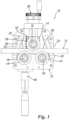
- an enhanced bending machine indicated by the reference numeral 10 as a whole, comprises a framework 12, which supports and accommodates the working members suitable for bending a tubular element or profile 13, driving and moving members for driving and moving said working members, and adjustment members for adjusting said working members.
- the working members comprise three operating rollers or pulleys, namely one movable roller 14 and two fixed rollers 14' and 14'', arranged in a triangle or delta " ⁇ " configuration, stabilized externally to the framework 12, by way of a key connection, by interference, or another known mode, on their respective output shafts 16, 16', and 16'', of which the output shaft 16 is mounted on the framework 12 so as to be movable and be capable of getting closer to/moving away from the output shafts 16' and 16'' which, on the contrary, are mounted fixed with respect to the framework, said shafts also having axes of rotation parallel to each other.
- the operating rollers or pulleys 14, 14', and 14'' are each provided with a circumferentially developed groove or race 15, the shape of which corresponds to the diameter and/or geometry of the tubular element or profile to be bent.
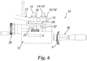
- the output shaft 16 is movable, hence capable of getting closer to/moving away from the output shafts 16' and 16'' by way of the working member adjustment means, said adjusting means comprising a guide 18 slidable with respect to the framework 12.
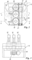
- Said side rollers 20 feature an axis of rotation perpendicular to the axis of rotation of the operating rollers or pulleys and are rotationally arranged idle with respect to the support elements 22, whose inclination in a plane perpendicular to the axes of rotation of the operating rollers or pulleys can be adjusted by way of an adjustment ring nut 23, which each individual support element is provided with.
- a rotatably supported, worm-toothed shaft 26 Internally to the framework 12 there is arranged a rotatably supported, worm-toothed shaft 26, the axis of rotation of which is perpendicular to that of the shafts of the operating rollers or pulleys by way of bearings 27 or equivalently known rotational support elements.
- said worm-toothed shaft 26 is, as better described below, to allow for a simultaneous rotational driving of the operating rollers or pulleys, namely the movable one 14 and the fixed ones 14' and 14'', so as to bend tubular elements or profiles.
- the movement of the guide 18 and, consequently, of the output shaft 16 which supports the operating roller or pulley 14, i.e. the movable roller, with respect to the fixed rollers 14' and 14'' is performed manually by way of an adjustment knob or handwheel 30 (an adjustment vernier) which allows for an accurate and micrometric adjustment (along a graduated scale 18') of the position of the guide 18 between a maximum separation position with respect to the fixed rollers or pulleys 14' and 14'' (position A) and a minimum separation position from the mentioned rollers (position B) so as to define a displacement indicated by "X" in figure 2 .
- an adjustment knob or handwheel 30 an adjustment vernier
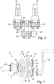
- the rotation of the operating roller or pulley 14 takes place by way of a toothed wheel 32 which meshes the worm-toothed shaft 26 (in any positions determined by adjusting the guide 18), said toothed wheel being secured to the movable shaft 16; the same toothed wheel 32 forces the movable output shaft 16 to rotate with respect to its own axis as described below in details.
- a transmission 34 which comprises a transmission shaft 36, a first toothed transmission wheel 38 put in said transmission shaft and mesh-coupled with the worm-toothed shaft 26, a second toothed transmission wheel 39 which is coupled with a first gear-roller 40 and with a second gear-roller 42 secured onto the fixed output shaft 16' and output shaft 16'' respectively.
- the worm-toothed shaft 26 and the transmission 34 make up the member that drives the bending machine according to the invention which, owing to its own rotation, allows to simultaneously and synchronously move the movable output shaft 16 counterclockwise, in a direct manner, and the fixed shafts 16' and 16'' clockwise, in an indirect manner, by way of the transmission 34.
- a tubular element 13 to be bent is loaded onto the bending machine and arranged between the operating rollers or pulleys 14, 14', and 14'', as shown in figure 1 , the outer surface of said tubular element coupling with the grooves or races 15 of the mentioned operating rollers or pulleys and is also being in contact with the surfaces of the opposed side rollers 20.
- the position of the fixed operating roller or pulley 14 is manually adjusted by an operator by way of the guide 18, by acting on the knob or handwheel 30 which, by rotating according to the direction of the arrow "Y" in figure 5 , causes a translational movement of the guide 18 according to the direction "X" and, consequently, the movement of the output shaft 16 which the operating roller or pulley 14 is put in; in this way, the operating roller or pulley 14 exerts a pressure onto the tubular element 13.
- the tubular element 13 is bent by making it slide between the operating rollers or pulleys by increasing or decreasing the distance of the movable operating roller or pulley 14 with respect to the fixed rollers or pulleys 14' and 14'' between position A and position B; as the guide 18 moves from position A to position B, the distance between the movable roller or pulley 14 and the fixed rollers or pulleys 14' and 14'' decreases and, in this way, the bending radius to be given to the tubular element becomes smaller.
- the operator will bend a tubular element through a number of successive passages by varying each time the value for the displacement "X", i.e. by varying the position of the movable shaft 16 which supports the movable roller or pulley 14 with respect to the shafts 14' and 14'' by acting on the adjustment knob or handwheel 30.
- the enhanced bending machine as described above with reference to one manual operation embodiment can also be implemented in an electrical operation mode, which comprises an electric driving suitable for rotationally driving the worm-toothed shaft 26 which drives all three output shafts 16, 16', and 16'' into rotation.
- An enhanced bending machine according to the present invention of a three-shaft manually-operated or electrically-operated type, has all three shafts, drivers and is such as to allow to permanently have a constant pressure on the tubular element or profile during the bending step, while preventing it from slipping.
- the bending machine according to the invention having all three shafts drivers, one of which in position-adjustable and driver in any positions, makes it possible to realize smaller bending radii, the capacity or characteristic of the profile or tubular element being equal, as compared to a three-shaft bending machines of a traditional type.
- a further advantage is in that an enhanced bending machine according to the invention, wherein there are three driving shafts and the third shaft is simultaneously driver and movable, hence capable of getting closer to/moving away from the remaining two shafts, makes it possible to exert a pressure onto the tubular element in the bending step while preventing the latter from slipping and, consequently, residual deformations present in the tubular element during the bending step will be minor and reduced.
- a bending machine structured as described above makes it possible to perform bending operations on a tubular element while preventing oscillations from occurring in the tubular element itself in correspondence with its terminal part not held between the operating rollers or pulleys.
- a further advantage is in that the use of a worm screw makes it possible to have a bending machine featuring reduced space occupation and also easy to transport.
Landscapes
- Engineering & Computer Science (AREA)
- Mechanical Engineering (AREA)
- Bending Of Plates, Rods, And Pipes (AREA)
Claims (8)
- Verbesserte Biegemaschine (10), geeignet zum Ausführen von Biegevorgängen gemäß bestimmter Formen und/oder Muster für ein rohrförmiges Element oder Profil (13), umfassend ein Rahmengestell (12), das Arbeitselemente, die zum Biegen eines rohrförmigen Elements oder Profils (13) geeignet sind, stützt und aufnimmt, Antriebs- und Bewegungselemente zum Antreiben und Bewegen der Arbeitselemente und Einstellelemente zum Anpassen der Arbeitselemente, wobei die Arbeitselemente drei Betriebsollen oder Riemenscheiben (14, 14', 14") umfassen, die von ihren jeweiligen Ausgangswellen (16, 16', 16") getragen werden, wobei eine Ausgangswelle (16) beweglich ist und sich dadurch näher an die Ausgangswellen (16', 16") heranbewegen/von diesen entfernen kann, deren Position mittels Einstellelementen befestigt ist, die eine Führung (18) umfasst die die Ausgangswelle (16) stützt und in Bezug auf das Rahmengestell (12) verschiebbar ist, wobei die Biegemaschine dadurch gekennzeichnet ist, dass alle die Betriebsrollen oder Riemenscheiben (14, 14', 14") stützenden drei Ausgangswellen (16, 16', 16") über dasselbe Antriebselement angetrieben werden, das eine Schneckenwelle (26) umfasst, die die im Inneren des Rahmengestells (12) angeordnet und drehbar gelagert ist, wobei die Drehachse senkrecht zu der Ausgangswellen (16, 16', 16") verläuft, wobei der Drehantrieb der beweglichen Ausgangswelle (16) über ein Zahnrad (32) erfolgt, das in die Schneckenwelle (26) eingreift und an der beweglichen Welle (16) befestigt ist, und mit dem Zahnrad (32), welches die bewegliche Ausgangswelle (16) zwingt, sich in Bezug auf ihre eigene Achse zu drehen, und der rotierende Antrieb der befestigten Ausgangswellen (16', 16") wird mittels eines Getriebes (34) durchgeführt, welches die Bewegung von derselben Schneckenwelle (26) erhält.
- Biegemaschine nach Anspruch 1, dadurch gekennzeichnet, dass die drei Betriebsrollen oder Riemenscheiben (14, 14', 14") in einer Dreieck- oder Delta-"Δ"-Konfiguration angeordnet sind, die außerhalb des Rahmengestells (12) stabilisiert ist und in ihre jeweiligen Ausgangswellen (16, 16', 16") eingesetzt ist, deren Drehachsen parallel zueinander sind.
- Biegemaschine gemäß Anspruch 1 oder 2, dadurch gekennzeichnet, dass die Führung (18) mittels eines Nonius entlang einer abgestuften Skala (18') zwischen einer maximalen Abstandsposition in Bezug auf die befestigten Betriebsrollen oder Riemenscheiben (14', 14") (Position A) und einer minimalen Abstandsposition in Bezug auf die erwähnten Rollen (Position B) angepasst werden kann, um eine durch ,X' angegebene Verschiebung zu definieren.
- Biegemaschine gemäß einem oder mehreren der vorstehenden Ansprüche, dadurch gekennzeichnet, dass das Getriebe (34) eine Getriebewelle (36) umfasst, deren Drehachse senkrecht zur Drehachse der Schneckenwelle (26) ist, wobei ein erstes Zahnrad (38) in die Getriebewelle eingesetzt und mit der Schneckenwelle (26) in Eingriff steht, wobei ein zweites Zahnrad (39) in derselben Getriebewelle (36) angeordnet ist und mit einer ersten Antriebsrolle (40) und einer zweiten Antriebsrolle (42) gekoppelt ist, die jeweils an der befestigten Ausgangswelle (16') und der Ausgangswelle (16") befestigt sind.
- Biegemaschine gemäß einem oder mehreren der vorstehenden Ansprüche, dadurch gekennzeichnet, dass sie außerhalb des Rahmengestells (12) und auf derselben Seite, auf der die Betriebssrollen oder Riemenscheiben (14, 14', 14") angeordnet sind, ein Paar gegenüberliegender Seitenrollen (20) umfasst, die voneinander beabstandet sind, so dass die Betriebsrollen oder Riemenscheiben in dem Bereich zwischen den Seitenrollen (20) positioniert sind, wobei die Seitenrollen eine Drehachse senkrecht zur Drehachse der Betriebsrollen oder Riemenscheiben (14, 14', 14") aufweisen und in Bezug auf die Stützelemente (22) leerlaufend drehbar gelagert sind.
- Biegemaschine nach Anspruch 5, dadurch gekennzeichnet, dass die Stützelemente (22), die die Seitenrollen (20) stützen, eine einstellbare Neigung in einer Ebene senkrecht zu den Drehachsen der Betriebsrollen oder Riemenscheiben (14, 14', 14") aufweisen, die über eine an jedem Stützelement befestigte Einstellringmutter (23) angepasst werden kann.
- Biegemaschine gemäß einem oder mehreren der vorstehenden Ansprüche, dadurch gekennzeichnet, dass sie manuell betrieben wird und einen Einstellknopf oder ein Handrad (30) umfasst, das gemäß einer Drehachse senkrecht zur Drehachse der Ausgangswellen (16, 16', 16") drehbar ist und dazu geeignet ist, die Position der Führung (18) so anzupassen, dass sie näher an die /von den befestigten Ausgangswellen (16', 16") weg bewegt wird, und ein weiteres Handrad oder eine Kurbel (46) umfasst, deren Drehachse senkrecht zur Drehachse der Ausgangswellen (16, 16', 16") steht, auf der gegenüberliegenden Seite in Bezug auf das Handrad oder den Knopf (30) angeordnet und an der Schneckenwelle (26) befestigt ist.
- Biegemaschine nach einem oder mehreren der vorstehenden Ansprüche 1 bis 7, dadurch gekennzeichnet, dass es sich um eine elektrisch betriebene handelt, die über einen an der Schneckenwelle (26) befestigten Motor betrieben wird.
Applications Claiming Priority (1)
| Application Number | Priority Date | Filing Date | Title |
|---|---|---|---|
| IT102017000051909A IT201700051909A1 (it) | 2017-05-12 | 2017-05-12 | Calandra perfezionata |
Publications (3)
| Publication Number | Publication Date |
|---|---|
| EP3401031A1 EP3401031A1 (de) | 2018-11-14 |
| EP3401031C0 EP3401031C0 (de) | 2024-10-23 |
| EP3401031B1 true EP3401031B1 (de) | 2024-10-23 |
Family
ID=60020333
Family Applications (1)
| Application Number | Title | Priority Date | Filing Date |
|---|---|---|---|
| EP18171674.7A Active EP3401031B1 (de) | 2017-05-12 | 2018-05-10 | Verbesserte biegemaschine |
Country Status (2)
| Country | Link |
|---|---|
| EP (1) | EP3401031B1 (de) |
| IT (1) | IT201700051909A1 (de) |
Families Citing this family (9)
| Publication number | Priority date | Publication date | Assignee | Title |
|---|---|---|---|---|
| CN109967576A (zh) * | 2019-04-17 | 2019-07-05 | 宁国中奕橡塑有限公司 | 一种减震圈组件外骨架成型工艺 |
| CN110434560B (zh) * | 2019-08-19 | 2020-12-08 | 扬州吉星机械有限公司 | 一种异形焊管加工设备及其加工工艺 |
| CN111421033B (zh) * | 2020-06-10 | 2020-10-13 | 广东高谱弯曲技术有限公司 | 轮轴支架及具有该轮轴支架的滚弯机 |
| CN112620422A (zh) * | 2020-11-09 | 2021-04-09 | 陈子冈 | 一种可调试钢管折弯机 |
| CN112705601A (zh) * | 2020-12-09 | 2021-04-27 | 国网河南省电力公司孟州市供电公司 | 一种电力用穿线铁管弯曲机 |
| CN113634639B (zh) * | 2021-09-14 | 2024-06-07 | 江苏申阳电梯部件有限公司 | 一种带翻边的薄壁型材滚弯机 |
| CN114011924A (zh) * | 2021-10-19 | 2022-02-08 | 钱子岑 | 一种铝型材折弯装置 |
| CN114147104B (zh) * | 2021-11-30 | 2024-04-12 | 中芯晟捷(江苏)精密科技有限公司 | 一种铝合金锭加工成型用的折弯装置 |
| DE102022108739A1 (de) | 2022-04-11 | 2023-10-12 | Peri Se | Verfahren zur Herstellung eines Gerüstbelags |
Family Cites Families (3)
| Publication number | Priority date | Publication date | Assignee | Title |
|---|---|---|---|---|
| US2467671A (en) * | 1943-11-02 | 1949-04-19 | Twentieth Cent Fox Film Corp | Pipe-bending machine |
| US4040283A (en) * | 1976-11-02 | 1977-08-09 | Patsy Suriano | Bending rolls machine |
| JPS60108119A (ja) * | 1983-11-16 | 1985-06-13 | Yasunaga Suezaki | ベンデイングマシン |
-
2017
- 2017-05-12 IT IT102017000051909A patent/IT201700051909A1/it unknown
-
2018
- 2018-05-10 EP EP18171674.7A patent/EP3401031B1/de active Active
Also Published As
| Publication number | Publication date |
|---|---|
| EP3401031A1 (de) | 2018-11-14 |
| EP3401031C0 (de) | 2024-10-23 |
| IT201700051909A1 (it) | 2018-11-12 |
Similar Documents
| Publication | Publication Date | Title |
|---|---|---|
| EP3401031B1 (de) | Verbesserte biegemaschine | |
| JP4610555B2 (ja) | パイプおよび管状材料を矯正する装置 | |
| CN219966103U (zh) | 一种弯折角度可调的工业自动化铝材弯折设备 | |
| WO2016097984A1 (en) | Bending machine for bending tubes, profiled sections, sheets and the like, with a measuring system for measuring the reaction force applied by the workpiece on the bending roller(s) of the machine | |
| US3656331A (en) | Apparatus for producing annular corrugated tubing | |
| US4304348A (en) | Roll type sheet material feeding apparatus | |
| JPH04742B2 (de) | ||
| US3422652A (en) | Method and machine for changing the curvature of elongated workpieces | |
| US5000364A (en) | Apparatus for obtaining differential tangential variable speeds at different points of a deformable film | |
| EP3283241B1 (de) | Verfahren und vorrichtung zur herstellung von plattenteilen für einen wärmetauscher | |
| US20140000762A1 (en) | Process and Device for Producing Parts, Notably Elongated Revolving Parts, by Machining a Bar Held Fixed in Rotation | |
| GB2559865A (en) | Machining tool | |
| JP7120591B2 (ja) | ロール成形装置 | |
| JP6240011B2 (ja) | 長尺材のロール曲げ装置及び曲げ加工方法 | |
| ITRM950309A1 (it) | Centinatrice universale. | |
| TWI235707B (en) | Roll device | |
| RU2622197C1 (ru) | Устройство для изготовления изогнутых труб | |
| CN113695434B (zh) | 钢管精成型装置 | |
| JP2007057040A (ja) | 無段変速装置 | |
| US2901930A (en) | Tube bending machines | |
| US4580942A (en) | Device for the manipulation of workpieces, assembly parts, or the like | |
| US4823580A (en) | Wheel-body forming apparatus | |
| CN102141792A (zh) | 数字控制凸轮机构及其控制方法 | |
| ITTO960142A1 (it) | Testa traspositrice per la formazione di conduttori ctc. | |
| CN113102649A (zh) | 一种蛇形折弯机 |
Legal Events
| Date | Code | Title | Description |
|---|---|---|---|
| PUAI | Public reference made under article 153(3) epc to a published international application that has entered the european phase |
Free format text: ORIGINAL CODE: 0009012 |
|
| STAA | Information on the status of an ep patent application or granted ep patent |
Free format text: STATUS: THE APPLICATION HAS BEEN PUBLISHED |
|
| AK | Designated contracting states |
Kind code of ref document: A1 Designated state(s): AL AT BE BG CH CY CZ DE DK EE ES FI FR GB GR HR HU IE IS IT LI LT LU LV MC MK MT NL NO PL PT RO RS SE SI SK SM TR |
|
| AX | Request for extension of the european patent |
Extension state: BA ME |
|
| STAA | Information on the status of an ep patent application or granted ep patent |
Free format text: STATUS: REQUEST FOR EXAMINATION WAS MADE |
|
| 17P | Request for examination filed |
Effective date: 20190506 |
|
| RBV | Designated contracting states (corrected) |
Designated state(s): AL AT BE BG CH CY CZ DE DK EE ES FI FR GB GR HR HU IE IS IT LI LT LU LV MC MK MT NL NO PL PT RO RS SE SI SK SM TR |
|
| STAA | Information on the status of an ep patent application or granted ep patent |
Free format text: STATUS: EXAMINATION IS IN PROGRESS |
|
| 17Q | First examination report despatched |
Effective date: 20220113 |
|
| GRAP | Despatch of communication of intention to grant a patent |
Free format text: ORIGINAL CODE: EPIDOSNIGR1 |
|
| STAA | Information on the status of an ep patent application or granted ep patent |
Free format text: STATUS: GRANT OF PATENT IS INTENDED |
|
| INTG | Intention to grant announced |
Effective date: 20240522 |
|
| GRAS | Grant fee paid |
Free format text: ORIGINAL CODE: EPIDOSNIGR3 |
|
| GRAA | (expected) grant |
Free format text: ORIGINAL CODE: 0009210 |
|
| STAA | Information on the status of an ep patent application or granted ep patent |
Free format text: STATUS: THE PATENT HAS BEEN GRANTED |
|
| AK | Designated contracting states |
Kind code of ref document: B1 Designated state(s): AL AT BE BG CH CY CZ DE DK EE ES FI FR GB GR HR HU IE IS IT LI LT LU LV MC MK MT NL NO PL PT RO RS SE SI SK SM TR |
|
| REG | Reference to a national code |
Ref country code: GB Ref legal event code: FG4D |
|
| REG | Reference to a national code |
Ref country code: CH Ref legal event code: EP |
|
| REG | Reference to a national code |
Ref country code: DE Ref legal event code: R096 Ref document number: 602018075674 Country of ref document: DE |
|
| REG | Reference to a national code |
Ref country code: IE Ref legal event code: FG4D |
|
| U01 | Request for unitary effect filed |
Effective date: 20241114 |
|
| U07 | Unitary effect registered |
Designated state(s): AT BE BG DE DK EE FI FR IT LT LU LV MT NL PT RO SE SI Effective date: 20241120 |
|
| PG25 | Lapsed in a contracting state [announced via postgrant information from national office to epo] |
Ref country code: HR Free format text: LAPSE BECAUSE OF FAILURE TO SUBMIT A TRANSLATION OF THE DESCRIPTION OR TO PAY THE FEE WITHIN THE PRESCRIBED TIME-LIMIT Effective date: 20241023 Ref country code: IS Free format text: LAPSE BECAUSE OF FAILURE TO SUBMIT A TRANSLATION OF THE DESCRIPTION OR TO PAY THE FEE WITHIN THE PRESCRIBED TIME-LIMIT Effective date: 20250223 |
|
| U20 | Renewal fee for the european patent with unitary effect paid |
Year of fee payment: 8 Effective date: 20250312 |
|
| PG25 | Lapsed in a contracting state [announced via postgrant information from national office to epo] |
Ref country code: ES Free format text: LAPSE BECAUSE OF FAILURE TO SUBMIT A TRANSLATION OF THE DESCRIPTION OR TO PAY THE FEE WITHIN THE PRESCRIBED TIME-LIMIT Effective date: 20241023 |
|
| PG25 | Lapsed in a contracting state [announced via postgrant information from national office to epo] |
Ref country code: NO Free format text: LAPSE BECAUSE OF FAILURE TO SUBMIT A TRANSLATION OF THE DESCRIPTION OR TO PAY THE FEE WITHIN THE PRESCRIBED TIME-LIMIT Effective date: 20250123 |
|
| PG25 | Lapsed in a contracting state [announced via postgrant information from national office to epo] |
Ref country code: GR Free format text: LAPSE BECAUSE OF FAILURE TO SUBMIT A TRANSLATION OF THE DESCRIPTION OR TO PAY THE FEE WITHIN THE PRESCRIBED TIME-LIMIT Effective date: 20250124 |
|
| PG25 | Lapsed in a contracting state [announced via postgrant information from national office to epo] |
Ref country code: PL Free format text: LAPSE BECAUSE OF FAILURE TO SUBMIT A TRANSLATION OF THE DESCRIPTION OR TO PAY THE FEE WITHIN THE PRESCRIBED TIME-LIMIT Effective date: 20241023 |
|
| PG25 | Lapsed in a contracting state [announced via postgrant information from national office to epo] |
Ref country code: RS Free format text: LAPSE BECAUSE OF FAILURE TO SUBMIT A TRANSLATION OF THE DESCRIPTION OR TO PAY THE FEE WITHIN THE PRESCRIBED TIME-LIMIT Effective date: 20250123 |
|
| PG25 | Lapsed in a contracting state [announced via postgrant information from national office to epo] |
Ref country code: SM Free format text: LAPSE BECAUSE OF FAILURE TO SUBMIT A TRANSLATION OF THE DESCRIPTION OR TO PAY THE FEE WITHIN THE PRESCRIBED TIME-LIMIT Effective date: 20241023 |
|
| PG25 | Lapsed in a contracting state [announced via postgrant information from national office to epo] |
Ref country code: SK Free format text: LAPSE BECAUSE OF FAILURE TO SUBMIT A TRANSLATION OF THE DESCRIPTION OR TO PAY THE FEE WITHIN THE PRESCRIBED TIME-LIMIT Effective date: 20241023 |
|
| PG25 | Lapsed in a contracting state [announced via postgrant information from national office to epo] |
Ref country code: CZ Free format text: LAPSE BECAUSE OF FAILURE TO SUBMIT A TRANSLATION OF THE DESCRIPTION OR TO PAY THE FEE WITHIN THE PRESCRIBED TIME-LIMIT Effective date: 20241023 |
|
| PLBE | No opposition filed within time limit |
Free format text: ORIGINAL CODE: 0009261 |
|
| STAA | Information on the status of an ep patent application or granted ep patent |
Free format text: STATUS: NO OPPOSITION FILED WITHIN TIME LIMIT |
|
| 26N | No opposition filed |
Effective date: 20250724 |