EP3400918A1 - Improved tampon withdrawal system and method for the fabrication thereof - Google Patents
Improved tampon withdrawal system and method for the fabrication thereof Download PDFInfo
- Publication number
- EP3400918A1 EP3400918A1 EP17170366.3A EP17170366A EP3400918A1 EP 3400918 A1 EP3400918 A1 EP 3400918A1 EP 17170366 A EP17170366 A EP 17170366A EP 3400918 A1 EP3400918 A1 EP 3400918A1
- Authority
- EP
- European Patent Office
- Prior art keywords
- string
- absorbent sheet
- absorbent
- withdrawal
- sheet
- Prior art date
- Legal status (The legal status is an assumption and is not a legal conclusion. Google has not performed a legal analysis and makes no representation as to the accuracy of the status listed.)
- Granted
Links
Images



Classifications
-
- A—HUMAN NECESSITIES
- A61—MEDICAL OR VETERINARY SCIENCE; HYGIENE
- A61F—FILTERS IMPLANTABLE INTO BLOOD VESSELS; PROSTHESES; DEVICES PROVIDING PATENCY TO, OR PREVENTING COLLAPSING OF, TUBULAR STRUCTURES OF THE BODY, e.g. STENTS; ORTHOPAEDIC, NURSING OR CONTRACEPTIVE DEVICES; FOMENTATION; TREATMENT OR PROTECTION OF EYES OR EARS; BANDAGES, DRESSINGS OR ABSORBENT PADS; FIRST-AID KITS
- A61F13/00—Bandages or dressings; Absorbent pads
- A61F13/15—Absorbent pads, e.g. sanitary towels, swabs or tampons for external or internal application to the body; Supporting or fastening means therefor; Tampon applicators
- A61F13/20—Tampons, e.g. catamenial tampons; Accessories therefor
- A61F13/2051—Tampons, e.g. catamenial tampons; Accessories therefor characterised by the material or the structure of the inner absorbing core
- A61F13/206—Tampons made of rolled-up material
-
- A—HUMAN NECESSITIES
- A61—MEDICAL OR VETERINARY SCIENCE; HYGIENE
- A61F—FILTERS IMPLANTABLE INTO BLOOD VESSELS; PROSTHESES; DEVICES PROVIDING PATENCY TO, OR PREVENTING COLLAPSING OF, TUBULAR STRUCTURES OF THE BODY, e.g. STENTS; ORTHOPAEDIC, NURSING OR CONTRACEPTIVE DEVICES; FOMENTATION; TREATMENT OR PROTECTION OF EYES OR EARS; BANDAGES, DRESSINGS OR ABSORBENT PADS; FIRST-AID KITS
- A61F13/00—Bandages or dressings; Absorbent pads
- A61F13/15—Absorbent pads, e.g. sanitary towels, swabs or tampons for external or internal application to the body; Supporting or fastening means therefor; Tampon applicators
- A61F13/20—Tampons, e.g. catamenial tampons; Accessories therefor
- A61F13/2082—Apparatus or processes of manufacturing
- A61F13/2085—Catamenial tampons
- A61F13/2094—Catamenial tampons rolling a web material to form a tampon
-
- A—HUMAN NECESSITIES
- A61—MEDICAL OR VETERINARY SCIENCE; HYGIENE
- A61F—FILTERS IMPLANTABLE INTO BLOOD VESSELS; PROSTHESES; DEVICES PROVIDING PATENCY TO, OR PREVENTING COLLAPSING OF, TUBULAR STRUCTURES OF THE BODY, e.g. STENTS; ORTHOPAEDIC, NURSING OR CONTRACEPTIVE DEVICES; FOMENTATION; TREATMENT OR PROTECTION OF EYES OR EARS; BANDAGES, DRESSINGS OR ABSORBENT PADS; FIRST-AID KITS
- A61F13/00—Bandages or dressings; Absorbent pads
- A61F13/15—Absorbent pads, e.g. sanitary towels, swabs or tampons for external or internal application to the body; Supporting or fastening means therefor; Tampon applicators
- A61F13/20—Tampons, e.g. catamenial tampons; Accessories therefor
- A61F13/34—Means for withdrawing tampons, e.g. withdrawal strings
Definitions
- the invention pertains to the technical field of withdrawal systems for digital tampons, and methods for the fabrication thereof. More in particular, the invention describes digital tampons, comprising an essentially cylindrical absorbent body and a withdrawal string, in which the contact length of the withdrawal string and the absorbent body is enlarged to prevent telescoping and breaking of the withdrawal string. Furthermore, the invention relates to a method for fabrication of said tampons.
- Tampons are well known in the art and are used for feminine hygiene. Also many tampon manufacturing methods and apparatuses have been disclosed in the prior art. Generally, a distinction is made between folded and rolled tampons. The former are commonly used with an applicator to reduce the chance of tears and other damage to the tampon. Most rolled tampons can be applied digitally, and comprise a rolled absorbent sheet and a withdrawal string for removal. The rolled absorbent sheet comprises an insertion end, a withdrawal end, and an essentially cylindrical body in between. The withdrawal string extends out of the withdrawal end. Sometimes rolled tampons also comprise a cover of a nonwoven, encapsulating the cylindrical body.
- an absorbent sheet with mutually orthogonal width and length directions is provided.
- the withdrawal string is looped in the width direction around the absorbent sheet, and subsequently the absorbent sheet is rolled around a rolling axis parallel to the width direction.
- a commonly encountered problem with rolled tampons is telescoping.
- the force acts on a single inner winding of the rolled absorbent sheet (also called absorbent body), and said winding moves with respect to the other windings.
- Figure 1 of document WO 2015/104301 illustrates telescoping. For convenience we have included said figure in FIG. 1 .
- the withdrawal string sometimes breaks at the turning point of the loop around the rolled absorbent sheet, as most of the pulling force attacks at this point.
- Document WO 2015/104301 proposes a cover made of a nonwoven which completely covers at least the withdrawal end with the exception of a through-opening for the withdrawal means to prevent telescoping as well as the escape of fibers from the withdrawal end.
- the proposed solution in document WO 2015/104301 is illustrated in FIGS. 2 and 3 .
- the cylindrical body comprises an absorbent body 1 and a cover made of a nonwoven 3 around the cylindrical body.
- a cover made of a nonwoven covers the withdrawal end 4 with the exception of a through-opening for the withdrawal string.
- the proposed solution in document WO 2015/104301 does not help to prevent breaking of the withdrawal string.
- Document US 3,976,075 proposes an absorbent sheet having printed on at least one surface thereof a non-occlusive pattern of adhesive binder.
- the resulting rolled tampon has a reduced tendency for telescoping and for fibrous particles to break loose from the cylindrical body.
- the non-occlusive pattern of adhesive binder can help to prevent breaking of the withdrawal string at the turning point of the loop around the rolled absorbent sheet.
- the proposed solution in document US 3,976,075 is illustrated in FIGS. 4 and 5 .
- the withdrawal string is connected adhesively to the cylindrical body, and the adhesive also interconnects the rolled absorbent sheet.
- FIGS. 6 and 7 The proposed solution in document US 4,787,895 is illustrated in FIGS. 6 and 7 .
- the generally continuous line of adhesive 5 along one side of the absorbent sheet 1 parallel to the length direction connects the withdrawal string 2 adhesively to the absorbent sheet 1 .
- the adhesive 5 also interconnects the rolled absorbent sheet 1 .
- the present invention pertains to a tampon comprising an absorbent body and a withdrawal string, whereby the absorbent body comprises an insertion end, a withdrawal end, and an essentially cylindrical body in between, whereby the cylindrical body further comprises a central axis, and whereby the withdrawal string extends out of the withdrawal end, characterized in that the withdrawal string follows within the absorbent body a string path comprising a helical portion around the central axis.
- a path comprising a helical portion around the central axis comprises a point on the path which does not lie on the axis, a longitudinal direction parallel to the central axis, a radial direction parallel to the shortest path connecting the point and the central axis, an orbital direction orthogonal to both the longitudinal and radial directions, and a tangent to the path through said point which comprises nonzero components along both the longitudinal and orbital directions.
- the loop of the withdrawal string 2 around the absorbent sheet 1 in the solutions of the prior art in FIGS. 2, 4, and 6 results in a minimal contact length between the withdrawal string 2 and the absorbent body 1 in FIGS. 3, 5, and 7 , respectively.
- the contact length of the withdrawal string and the absorbent body is enlarged.
- the tampon has a greater resistance to telescoping as the pulling force is spread over multiple windings of the absorbent sheet, and as the helical portion of the string path snares the absorbent body.
- the shear forces of the withdrawal string and the absorbent body are spread over a larger contact length, and a larger force can be applied to the withdrawal string before the latter will break.
- the present invention pertains to a method for the fabrication of said tampon, comprising the steps of
- the nonparallelity of the string application path with both the length and the width directions of the absorbent sheet results in an enlarged contact length of the string and the absorbent sheet.
- this corresponds to a string path comprising a helical portion around the central axis, and hence an enlarged contact length of the withdrawal string and the absorbent body.
- the tampon has a greater resistance to telescoping as the pulling force is spread over multiple windings of the absorbent sheet, and as the helical portion of the string path snares the absorbent body.
- the shear forces of the withdrawal string and the absorbent body are spread over a larger contact length, and a larger force can be applied to the withdrawal string before the latter will break.
- the method comprises the additional step in between steps c and d of folding the sheet and applied string, preferably around a folding axis essentially parallel to the width direction, more preferably around a folding axis essentially coinciding with the rolling axis.
- the method comprises the additional step before, during, or after step c and before step d of applying one or more nonwoven films comprising thermoplastic fibers fully or partially on to the absorbent sheet.
- the method comprises the additional step before, during, or after step c and before step d of detaching a piece of the provided absorbent sheet, preferably by cutting.
- the first portion of the string application path is essentially a straight line and the second portion of the string application path is essentially a straight line, whereby the lines make an angle with the width direction of preferably at least 5 degrees, more preferably at least 15 degrees, even more preferably at least 25 degrees, even more preferably at least 35 degrees, and even more preferably at least 45 degrees.
- the two straight lines are essentially parallel.
- the present invention concerns digital tampons with an improved withdrawal system, and methods for the fabrication thereof.
- the value to which the modifier "about” refers is itself also specifically disclosed.
- nonwoven means a sheet material having a structure of individual fibers or threads which are interlaid, but not in a regular manner such as occurs with knitting or weaving processes.
- Nonwoven fabrics or webs have been formed from many processes such as for example, meltblowing processes, spunbonding processes, and bonded carded web processes.
- thermoplastic is meant to describe a material that softens when exposed to heat and which substantially returns to its original condition when cooled to room temperature.
- a string is meant to describe a pliable long object with tensile strength.
- the term “string” as used herein can therefore be synonymous with “yarn”, “thread”, “twine”, “cord”, “lace”, “line”, or “rope”.
- a string can comprise natural or synthetic fibers. Examples of natural fibers are manila hemp, hemp, feathers, linen, cotton, coir, jute, straw, sisal, silk, wool, and animal hair. Examples of synthetic fibers are polypropylene, nylon, polyester, polyethylene, cellulose, and acrylics.
- a string can also comprise mixtures of several fibers and/or comprise copolymer fibers. The fibers are spun and/or twisted and/or braided together into a larger and stronger form.
- the present invention pertains to a tampon comprising an absorbent body and a withdrawal string, whereby the absorbent body comprises an insertion end, a withdrawal end, and an essentially cylindrical body in between, whereby the cylindrical body further comprises a central axis, and whereby the withdrawal string extends out of the withdrawal end, characterized in that the withdrawal string follows within the absorbent body a string path comprising a helical portion around the central axis.
- the withdrawal string follows within the absorbent body of the tampon a string path comprising a helical portion around the central axis.
- a helical portion around a central axis refers to a portion which does not lie on the axis and extends in a direction which has at least a longitudinal component and an orbital component, i.e. at any point of the helical portion, the tangent is not parallel to the central axis and does not lie in a plane perpendicular to the central axis.
- the helical portion curls around the central axis while also having a longitudinal extension.
- the helical portion also has a radial component, meaning that the distance between the central axis and the helical portion is not the same for all points of the helical portion.
- the loop of the withdrawal string 2 around the absorbent sheet 1 in the solutions of the prior art in FIGS. 2, 4, and 6 results in a minimal contact length between the withdrawal string 2 and the absorbent body in FIGS. 3, 5, and 7 , respectively.
- the contact length of the withdrawal string and the absorbent body is enlarged.
- the tampon has a greater resistance to telescoping as the pulling force is spread over multiple windings of the absorbent sheet, and as the helical portion of the string path snares the absorbent body.
- the shear forces of the withdrawal string and the absorbent body are spread over a larger contact length, and a larger force can be applied to the withdrawal string before the latter will break.
- the absorbent body of the tampon has a length measured along the central axis of preferably at least 2 cm and at most 15 cm, more preferably at least 3 cm and at most 11 cm, even more preferably at least 4 cm and at most 7 cm, such as 4 cm, 4.5 cm, 5 cm, 5.5 cm, 6 cm, 6.5 cm, 7 cm, or any value in between.
- the contact ratio is the ratio of the contact length of the withdrawal string and the absorbent body to the length of the absorbent body measured along the central axis. In the current state-of-the-art, this contact ratio is about 2, as the withdrawal string follows a string path in the absorbent body substantially parallel to the central axis.
- the contact ratio is preferably at least 2.0075 and at most 22.9475, more preferably at least 2.0705 and at most 11.5175, more preferably at least 2.2067 and at most 7.7274, even more preferably at least 2.4415 and at most 5.8476, and yet even more preferably at least 2.8284 and at most 4.7324, such as 2.83, 2.93, 3.03, 3.13, 3.23, 3.33, 3.43, 3.53, 3.63, 3.73, 3.83, 3.93, 4.03, 4.13, 4.23, 4.33, 4.43, 4.53, 4.63, 4.73, or any value in between.
- the telescoping resistance is a parameter which can be measured by clamping the cylindrical body of the tampon and by pulling with gradually increasing force the withdrawal cord in a direction parallel to the central axis of the tampon and away from the withdrawal end. Such measurement may be carried out by affixing (by use of clamp members or adhesive tape) the tampon to a first end and the withdrawal cord to a second end of a testcontroll II Switzerlandprüfmaschine (available at ZWICK GmbH & Co. KG) and apply a displacement of 1 cm/s moving said first and second ends in opposed directions. The force is recorded and the tampon is visually inspected during said displacement. The force at which the onset of telescoping occurs, as illustrated in FIG.
- the telescoping resistance is preferably at least 5 N, more preferably at least 10 N, even more preferably at least 15 N, such as 15 N, 16 N, 17 N, 18 N, 19 N, 20 N, 22 N, 24 N, 26 N, 28 N, 30 N, 35 N, 40 N, 45 N, 50 N, or any value in between or above.
- FIG. 9 is a schematic representation of a part of a tampon, in which the withdrawal string 2 follows within the absorbent body 1 a string path comprising a helical portion around the central axis.
- the contact length of the withdrawal string 2 with the absorbent body 1 is larger in FIG. 9 , resulting in a greater resistance to telescoping, and a larger force can be applied to the withdrawal string.
- the absorbent body comprises a hydrophilic absorbent fiber web.
- the absorbent body comprises a nonwoven cover comprising thermoplastic fibers.
- the present invention pertains to a method for the fabrication of said tampon, comprising the steps of
- the nonparallelity of the string application path with both the length and the width directions of the absorbent sheet results in an enlarged contact length of the string and the absorbent sheet.
- this corresponds to an enlarged contact length of the withdrawal string and the absorbent body.
- the tampon has a greater resistance to telescoping as the pulling force is spread over multiple windings of the absorbent sheet, and as the helical portion of the string path snares the absorbent body.
- the shear forces of the withdrawal string and the absorbent body are spread over a larger contact length, and a larger force can be applied to the withdrawal string before the latter will break.
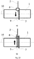
- the step of applying the string around the absorbent sheet is carried out by a string application apparatus and wherein at least a portion of said string application apparatus is arranged to contact the withdrawal string and/or absorbent sheet such that the string application path is substantially nonparallel to both the length direction and the width direction of the absorbent sheet, preferably wherein at least said portion of said string application apparatus comprising a contact axis that is at an angle substantially nonparallel to both the length axis 10 and the width axis 9 of the absorbent sheet, preferably said angle being from greater than 0° to less than 90°, more preferably between 15° and 75°, even more preferably between 25° and 65°, most preferably between 30° and 60°.
- a string contact element which may comprise one or more movable clamp-shaped members 8 , extending substantially perpendicular to said contact axis, and one or more conveying means 7 such as a conveyor belt, extending substantially parallel to said contact axis, whereby said clamp-shaped members 8 are attached to said conveying means 7 and whereby said clamp-shaped members 8 hold said string 2 while moving along said conveying means 7 thereby leading said string 2 around said absorbent sheet 1 along said contact axis and whereby said string 2 is released by the clamp-shaped members 8 to contact said absorbent sheet 1 once it has been essentially entirely lead around said absorbent sheet 1.
- a string contact element which may comprise one or more movable clamp-shaped members 8 , extending substantially perpendicular to said contact axis, and one or more conveying means 7 such as a conveyor belt, extending substantially parallel to said contact axis, whereby said clamp-shaped members 8 are attached to said conveying means 7 and whereby said clamp-shaped members 8 hold said string 2 while moving along said conveying means 7 thereby
- the provided absorbent sheet has a width measured along the width direction of preferably at least 2 cm and at most 15 cm, more preferably at least 3 cm and at most 11 cm, even more preferably at least 4 cm and at most 7 cm, such as 4 cm, 4.5 cm, 5 cm, 5.5 cm, 6 cm, 6.5 cm, 7 cm, or any value in between.
- the method comprises the additional step in between steps c and d of folding the sheet and applied string, preferably around a folding axis essentially parallel to the width direction, more preferably around a folding axis essentially coinciding with the rolling axis.
- the method comprises the additional step before, during, or after step c and before step d of applying one or more nonwoven films comprising thermoplastic fibers fully or partially on to the absorbent sheet.
- the method comprises the additional step before, during, or after step c and before step d of detaching a piece of the provided absorbent sheet, preferably by cutting.
- the first portion of the string application path is essentially a straight line and the second portion of the string application path is essentially a straight line, whereby the lines make an angle with the width direction of preferably at least 5 degrees, more preferably at least 15 degrees, even more preferably at least 25 degrees, even more preferably at least 35 degrees, and even more preferably at least 45 degrees.
- the two straight lines are essentially parallel.
- the angle of the two straight lines with the width direction is chosen to maximize the telescoping resistance of the finished tampon.
- step c during step c the first portion of the string application path has a continuously varying tangent and the second portion of the string application path has a continuously varying tangent.
- the absorbent sheet comprises a hydrophilic absorbent fiber web.
- FIGS. 10 , 14 , and 18 are schematic representations of an intermediate in the method to produce rolled tampons, in which the application path of the string 2 comprises a portion which is parallel to the absorbent sheet 1 and which is also significantly nonparallel to both the length and the width directions of the absorbent sheet 1.
- FIGS. 11 , 15 , and 19 show a part of the finished tampon based on the absorbent sheet 1 and applied string 2 in respectively FIGS. 10 , 14 , and 18 .
- the portions of the string application paths in between the first and second length edges of the absorbent sheet are straight lines.
- the portions of the string application paths in between the first and second length edges of the absorbent sheet are piecewise straight lines.
- the portions of the string application paths in between the first and second length edges of the absorbent sheet have a continuously varying tangent.
- FIGS. 8 , 12 , and 16 are schematic representations of an intermediate in the method to produce rolled tampons, in which the application path of the string 2 comprises a portion which is parallel to the absorbent sheet 1 and which is also significantly nonparallel to both the length and the width directions of the absorbent sheet 1, and in which a nonwoven film 3 comprising thermoplastic fibers has been applied on to the absorbent sheet 1.
- FIGS. 9 , 13 , and 17 show a part of the finished tampon based on the absorbent sheet 1 , applied string 2 , and nonwoven film 3 in respectively FIGS. 8 , 12 , and 16 .
- the portions of the string application paths in between the first and second length edges of the absorbent sheet are straight lines.
- FIG. 8 the portions of the string application paths in between the first and second length edges of the absorbent sheet are straight lines.
- the portions of the string application paths in between the first and second length edges of the absorbent sheet are piecewise straight lines.
- the portions of the string application paths in between the first and second length edges of the absorbent sheet have a continuously varying tangent.
- FIG. 20 is schematic representation of intermediate steps in the method to produce rolled tampons according to the present invention.
- an absorbent sheet 1 an applied string 2 , and a folding axis 6 are shown, whereby the string 2 follows a string path comprising a first straight line on the first side of the absorbent sheet 1 from the first length edge to the second length edge and a second straight line on the second side of the absorbent sheet 1 from the second length edge to the first length edge, whereby the two lines are essentially mutually parallel and essentially parallel to the absorbent sheet 1 .
- the sheet is subsequently folded around the folding axis 6 , resulting in the folded sheet 1 in FIG 20B .
- the folding axis 6 also serves as rolling axis to produce a tampon preform. Due to the particular string application path in FIG 20B , the string will follow inside the absorbent body a string path comprising two conical helices, with a common tip near the center of the essentially cylindrical body of the tampon preform.
- FIG 20C is a schematic representation of a projection of the string path inside the essentially cylindrical body of the tampon preform, as viewed from the withdrawal end.
- FIG 20D is a schematic representation of a projection of the string path inside the essentially cylindrical body of the tampon preform, as viewed from the side.
- a preferred embodiment of the method for the fabrication of a tampon comprises the steps of
- the string consists for 100% of organic cotton and has a tensile strength of 30 Newton.
- the string consists for 100% of organic cotton and has a tensile strength of 70 Newton.
- the string comprises 67% polyester and 33% cotton and has a tensile strength of 50 Newton.
Landscapes
- Health & Medical Sciences (AREA)
- Engineering & Computer Science (AREA)
- Life Sciences & Earth Sciences (AREA)
- Biomedical Technology (AREA)
- Heart & Thoracic Surgery (AREA)
- Vascular Medicine (AREA)
- Epidemiology (AREA)
- Animal Behavior & Ethology (AREA)
- General Health & Medical Sciences (AREA)
- Public Health (AREA)
- Veterinary Medicine (AREA)
- Manufacturing & Machinery (AREA)
- Absorbent Articles And Supports Therefor (AREA)
Abstract
Description
- The invention pertains to the technical field of withdrawal systems for digital tampons, and methods for the fabrication thereof. More in particular, the invention describes digital tampons, comprising an essentially cylindrical absorbent body and a withdrawal string, in which the contact length of the withdrawal string and the absorbent body is enlarged to prevent telescoping and breaking of the withdrawal string. Furthermore, the invention relates to a method for fabrication of said tampons.
- Tampons are well known in the art and are used for feminine hygiene. Also many tampon manufacturing methods and apparatuses have been disclosed in the prior art. Generally, a distinction is made between folded and rolled tampons. The former are commonly used with an applicator to reduce the chance of tears and other damage to the tampon. Most rolled tampons can be applied digitally, and comprise a rolled absorbent sheet and a withdrawal string for removal. The rolled absorbent sheet comprises an insertion end, a withdrawal end, and an essentially cylindrical body in between. The withdrawal string extends out of the withdrawal end. Sometimes rolled tampons also comprise a cover of a nonwoven, encapsulating the cylindrical body.
- During the manufacturing process of rolled tampons, an absorbent sheet with mutually orthogonal width and length directions is provided. The withdrawal string is looped in the width direction around the absorbent sheet, and subsequently the absorbent sheet is rolled around a rolling axis parallel to the width direction. A commonly encountered problem with rolled tampons is telescoping. When force is applied to the withdrawal string, the force acts on a single inner winding of the rolled absorbent sheet (also called absorbent body), and said winding moves with respect to the other windings.
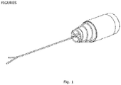
Figure 1 of documentWO 2015/104301 illustrates telescoping. For convenience we have included said figure inFIG. 1 . In addition, the withdrawal string sometimes breaks at the turning point of the loop around the rolled absorbent sheet, as most of the pulling force attacks at this point. - Document
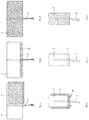
WO 2015/104301 proposes a cover made of a nonwoven which completely covers at least the withdrawal end with the exception of a through-opening for the withdrawal means to prevent telescoping as well as the escape of fibers from the withdrawal end. The proposed solution in documentWO 2015/104301 is illustrated inFIGS. 2 and 3 . InFIG. 3 , the cylindrical body comprises anabsorbent body 1 and a cover made of a nonwoven 3 around the cylindrical body. In addition, a cover made of a nonwoven covers the withdrawal end 4 with the exception of a through-opening for the withdrawal string. However, the proposed solution in documentWO 2015/104301 does not help to prevent breaking of the withdrawal string. - Document
US 3,976,075 proposes an absorbent sheet having printed on at least one surface thereof a non-occlusive pattern of adhesive binder. The resulting rolled tampon has a reduced tendency for telescoping and for fibrous particles to break loose from the cylindrical body. In addition, the non-occlusive pattern of adhesive binder can help to prevent breaking of the withdrawal string at the turning point of the loop around the rolled absorbent sheet. The proposed solution in documentUS 3,976,075 is illustrated inFIGS. 4 and 5 . - Document
US 4,787,895 proposes to place a generally continuous line of adhesive along one side of the absorbent sheet parallel to the length direction. - After rolling the sheet, the withdrawal string is connected adhesively to the cylindrical body, and the adhesive also interconnects the rolled absorbent sheet.
- This helps the tampon to resist telescoping during withdrawal and to prevent breaking of the withdrawal string at the turning point of the loop around the rolled absorbent sheet. The proposed solution in document
US 4,787,895 is illustrated inFIGS. 6 and 7 . InFIG. 6 , the generally continuous line ofadhesive 5 along one side of theabsorbent sheet 1 parallel to the length direction connects thewithdrawal string 2 adhesively to theabsorbent sheet 1. InFIG. 7 , theadhesive 5 also interconnects the rolledabsorbent sheet 1. - The abovementioned prior art has the common disadvantage that additional material and additional production steps are needed to achieve a greater resistance to telescoping and/or to prevent breaking of the withdrawal string at the turning point of the loop around the rolled absorbent sheet. The solution in document
WO 2015/104301 requires extra nonwoven and the application of the extra nonwoven on the withdrawal end. The solution in documentUS 3,976,075 requires an extra non-occlusive pattern of adhesive binder and the application thereof on the absorbent sheet. The solution in documentUS 4,787,895 requires an extra generally continuous line of adhesive and the application thereof on the absorbent sheet. - Our solution circumvents this disadvantage.
- In a first aspect, the present invention pertains to a tampon comprising an absorbent body and a withdrawal string, whereby the absorbent body comprises an insertion end, a withdrawal end, and an essentially cylindrical body in between, whereby the cylindrical body further comprises a central axis, and whereby the withdrawal string extends out of the withdrawal end, characterized in that the withdrawal string follows within the absorbent body a string path comprising a helical portion around the central axis.
- A path comprising a helical portion around the central axis, comprises a point on the path which does not lie on the axis, a longitudinal direction parallel to the central axis, a radial direction parallel to the shortest path connecting the point and the central axis, an orbital direction orthogonal to both the longitudinal and radial directions, and a tangent to the path through said point which comprises nonzero components along both the longitudinal and orbital directions.
- The loop of the
withdrawal string 2 around theabsorbent sheet 1 in the solutions of the prior art inFIGS. 2, 4, and 6 results in a minimal contact length between thewithdrawal string 2 and theabsorbent body 1 inFIGS. 3, 5, and 7 , respectively. When the string follows within the absorbent body a string path comprising a helical portion around the central axis, the contact length of the withdrawal string and the absorbent body is enlarged. As a result, the tampon has a greater resistance to telescoping as the pulling force is spread over multiple windings of the absorbent sheet, and as the helical portion of the string path snares the absorbent body. In addition, the shear forces of the withdrawal string and the absorbent body are spread over a larger contact length, and a larger force can be applied to the withdrawal string before the latter will break. - In a second aspect, the present invention pertains to a method for the fabrication of said tampon, comprising the steps of
- a. providing an absorbent sheet which comprises a first length edge, a second length edge essentially parallel to the first length edge, a length direction essentially parallel to the first and second length edges, a width direction parallel to the sheet and orthogonal to the length direction, a first side of the sheet, and a second side of the sheet,
- b. providing a string,
- c. applying the string around the absorbent sheet, whereby the string follows a string path comprising a first portion on the first side of the sheet from the first length edge to the second length edge and a second portion on the second side of the sheet from the second length edge to the first length edge,
- d. rolling up the sheet and applied string, preferably around a rolling axis essentially parallel to the width direction, thereby obtaining a tampon preform,
- e. finishing the tampon from the tampon preform,
- The nonparallelity of the string application path with both the length and the width directions of the absorbent sheet results in an enlarged contact length of the string and the absorbent sheet. In the finished tampon, this corresponds to a string path comprising a helical portion around the central axis, and hence an enlarged contact length of the withdrawal string and the absorbent body. As a result, the tampon has a greater resistance to telescoping as the pulling force is spread over multiple windings of the absorbent sheet, and as the helical portion of the string path snares the absorbent body. In addition, the shear forces of the withdrawal string and the absorbent body are spread over a larger contact length, and a larger force can be applied to the withdrawal string before the latter will break.
- In a preferred embodiment of the method, the method comprises the additional step in between steps c and d of folding the sheet and applied string, preferably around a folding axis essentially parallel to the width direction, more preferably around a folding axis essentially coinciding with the rolling axis.
- In a preferred embodiment of the method, the method comprises the additional step before, during, or after step c and before step d of applying one or more nonwoven films comprising thermoplastic fibers fully or partially on to the absorbent sheet.
- In a preferred embodiment of the method, in which the provided absorbent sheet extends significantly in the length direction, the method comprises the additional step before, during, or after step c and before step d of detaching a piece of the provided absorbent sheet, preferably by cutting.
- In a preferred embodiment of the method, during step c the first portion of the string application path is essentially a straight line and the second portion of the string application path is essentially a straight line, whereby the lines make an angle with the width direction of preferably at least 5 degrees, more preferably at least 15 degrees, even more preferably at least 25 degrees, even more preferably at least 35 degrees, and even more preferably at least 45 degrees. In an even more preferred embodiment of the method, the two straight lines are essentially parallel.
-
-
Figure 1 is a schematic representation illustrating the effect of telescoping in rolled tampons. -
Figure 2 is a schematic representation illustrating an intermediate in the method to produce the rolled tampon described in documentWO 2015/104301. -
Figure 3 is a schematic representation of a part of the rolled tampon described in documentWO 2015/104301. -
Figure 4 is a schematic representation illustrating an intermediate in the method to produce the rolled tampon described in documentUS 3,976,075 . -
Figure 5 is a schematic representation of a part of the rolled tampon described in documentUS 3,976,075 . -
Figure 6 is a schematic representation illustrating an intermediate in the method to produce the rolled tampon described in documentUS 4,787,895 . -
Figure 7 is a schematic representation of a part of the rolled tampon described in documentUS 4,787,895 . -
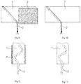
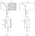
Figures 8, 10 ,12, 14 ,16, and 18 are schematic representations of string application paths in the method to produce rolled tampons according to the present invention. -
Figures 9, 11 ,13, 15 ,17, and 19 are schematic representations of parts of rolled tampons comprising a withdrawal string with a string path comprising a helical portion around the central axis of the tampon. -
Figure 20 is a schematic representation of intermediate steps in the method to produce rolled tampons according to the present invention. -
Figure 21 is a schematic representation of a string application apparatus in two intermediate positions during string application according to the present invention. -
Figure 22 is a schematic representation of a string application apparatus in two intermediate positions during string application with a contact axis essentially parallel to the length direction and essentially perpendicular to the length direction of the absorbent sheet according to the present invention. -
Figure 23 is a schematic representation of a string application apparatus in two intermediate positions during string application with a contact axis essentially non-parallel to the width direction and non-parallel to the length direction of the absorbent sheet according to the present invention. - The present invention concerns digital tampons with an improved withdrawal system, and methods for the fabrication thereof.
- Unless otherwise defined, all terms used in disclosing the invention, including technical and scientific terms, have the meaning as commonly understood by one of ordinary skill in the art to which this invention belongs. By means of further guidance, term definitions are included to better appreciate the teaching of the present invention.
- As used herein, the following terms have the following meanings:
- "A", "an", and "the" as used herein refers to both singular and plural referents unless the context clearly dictates otherwise. By way of example, "a compartment" refers to one or more than one compartment.
- "About" as used herein referring to a measurable value such as a parameter, an amount, a temporal duration, and the like, is meant to encompass variations of +/-20% or less, preferably +/-10% or less, more preferably +/-5% or less, even more preferably +/-1% or less, and still more preferably +/-0.1% or less of and from the specified value, in so far such variations are appropriate to perform in the disclosed invention. However, it is to be understood that the value to which the modifier "about" refers is itself also specifically disclosed.
- "Comprise", "comprising", "comprises" and "comprised of" as used herein are synonymous with "include", "including", "includes" or "contain", "containing", "contains" and are inclusive or open-ended terms that specify the presence of what follows e.g. component and do not exclude or preclude the presence of additional, non-recited components, features, elements, members, steps, known in the art or disclosed therein.
- The term "nonwoven" means a sheet material having a structure of individual fibers or threads which are interlaid, but not in a regular manner such as occurs with knitting or weaving processes. Nonwoven fabrics or webs have been formed from many processes such as for example, meltblowing processes, spunbonding processes, and bonded carded web processes.
- The term "thermoplastic" is meant to describe a material that softens when exposed to heat and which substantially returns to its original condition when cooled to room temperature.
- The term "string" is meant to describe a pliable long object with tensile strength. The term "string" as used herein can therefore be synonymous with "yarn", "thread", "twine", "cord", "lace", "line", or "rope". A string can comprise natural or synthetic fibers. Examples of natural fibers are manila hemp, hemp, feathers, linen, cotton, coir, jute, straw, sisal, silk, wool, and animal hair. Examples of synthetic fibers are polypropylene, nylon, polyester, polyethylene, cellulose, and acrylics. A string can also comprise mixtures of several fibers and/or comprise copolymer fibers. The fibers are spun and/or twisted and/or braided together into a larger and stronger form.
- In a first aspect, the present invention pertains to a tampon comprising an absorbent body and a withdrawal string, whereby the absorbent body comprises an insertion end, a withdrawal end, and an essentially cylindrical body in between, whereby the cylindrical body further comprises a central axis, and whereby the withdrawal string extends out of the withdrawal end, characterized in that the withdrawal string follows within the absorbent body a string path comprising a helical portion around the central axis.
- In the present invention, the withdrawal string follows within the absorbent body of the tampon a string path comprising a helical portion around the central axis. Herein, a helical portion around a central axis refers to a portion which does not lie on the axis and extends in a direction which has at least a longitudinal component and an orbital component, i.e. at any point of the helical portion, the tangent is not parallel to the central axis and does not lie in a plane perpendicular to the central axis. As a result, the helical portion curls around the central axis while also having a longitudinal extension. Optionally, the helical portion also has a radial component, meaning that the distance between the central axis and the helical portion is not the same for all points of the helical portion.
- The loop of the
withdrawal string 2 around theabsorbent sheet 1 in the solutions of the prior art inFIGS. 2, 4, and 6 results in a minimal contact length between thewithdrawal string 2 and the absorbent body inFIGS. 3, 5, and 7 , respectively. When the string follows within the absorbent body a string path comprising a helical portion around the central axis, the contact length of the withdrawal string and the absorbent body is enlarged. As a result, the tampon has a greater resistance to telescoping as the pulling force is spread over multiple windings of the absorbent sheet, and as the helical portion of the string path snares the absorbent body. In addition, the shear forces of the withdrawal string and the absorbent body are spread over a larger contact length, and a larger force can be applied to the withdrawal string before the latter will break. - In a preferred embodiment of the present invention, the absorbent body of the tampon has a length measured along the central axis of preferably at least 2 cm and at most 15 cm, more preferably at least 3 cm and at most 11 cm, even more preferably at least 4 cm and at most 7 cm, such as 4 cm, 4.5 cm, 5 cm, 5.5 cm, 6 cm, 6.5 cm, 7 cm, or any value in between.
- The contact ratio is the ratio of the contact length of the withdrawal string and the absorbent body to the length of the absorbent body measured along the central axis. In the current state-of-the-art, this contact ratio is about 2, as the withdrawal string follows a string path in the absorbent body substantially parallel to the central axis. In a preferred embodiment of the present invention, the contact ratio is preferably at least 2.0075 and at most 22.9475, more preferably at least 2.0705 and at most 11.5175, more preferably at least 2.2067 and at most 7.7274, even more preferably at least 2.4415 and at most 5.8476, and yet even more preferably at least 2.8284 and at most 4.7324, such as 2.83, 2.93, 3.03, 3.13, 3.23, 3.33, 3.43, 3.53, 3.63, 3.73, 3.83, 3.93, 4.03, 4.13, 4.23, 4.33, 4.43, 4.53, 4.63, 4.73, or any value in between.
- The telescoping resistance is a parameter which can be measured by clamping the cylindrical body of the tampon and by pulling with gradually increasing force the withdrawal cord in a direction parallel to the central axis of the tampon and away from the withdrawal end. Such measurement may be carried out by affixing (by use of clamp members or adhesive tape) the tampon to a first end and the withdrawal cord to a second end of a testcontroll II Zugprüfmaschine (available at ZWICK GmbH & Co. KG) and apply a displacement of 1 cm/s moving said first and second ends in opposed directions. The force is recorded and the tampon is visually inspected during said displacement. The force at which the onset of telescoping occurs, as illustrated in
FIG. 1 and described above, is recorded and the latter being the telescoping resistance as referred to herein. In a preferred embodiment of the present invention, the telescoping resistance is preferably at least 5 N, more preferably at least 10 N, even more preferably at least 15 N, such as 15 N, 16 N, 17 N, 18 N, 19 N, 20 N, 22 N, 24 N, 26 N, 28 N, 30 N, 35 N, 40 N, 45 N, 50 N, or any value in between or above. -
FIG. 9 is a schematic representation of a part of a tampon, in which thewithdrawal string 2 follows within the absorbent body 1 a string path comprising a helical portion around the central axis. Compared toFIGS. 3, 5, and 7 , the contact length of thewithdrawal string 2 with theabsorbent body 1 is larger inFIG. 9 , resulting in a greater resistance to telescoping, and a larger force can be applied to the withdrawal string. - In a preferred embodiment of the tampon, the absorbent body comprises a hydrophilic absorbent fiber web.
- In a preferred embodiment of the tampon, the absorbent body comprises a nonwoven cover comprising thermoplastic fibers.
- In a second aspect, the present invention pertains to a method for the fabrication of said tampon, comprising the steps of
- a. providing an absorbent sheet which comprises a first length edge, a second length edge essentially parallel to the first length edge, a length direction essentially parallel to the first and second length edges, a width direction parallel to the sheet and orthogonal to the length direction, a first side of the sheet, and a second side of the sheet,
- b. providing a string,
- c. applying the string around the absorbent sheet, whereby the string follows a string path comprising a first portion on the first side of the sheet from the first length edge to the second length edge and a second portion on the second side of the sheet from the second length edge to the first length edge,
- d. rolling up the sheet and applied string, preferably around a rolling axis essentially parallel to the width direction, thereby obtaining a tampon preform,
- e. finishing the tampon from the tampon preform,
- The nonparallelity of the string application path with both the length and the width directions of the absorbent sheet results in an enlarged contact length of the string and the absorbent sheet. In the finished tampon, this corresponds to an enlarged contact length of the withdrawal string and the absorbent body. As a result, the tampon has a greater resistance to telescoping as the pulling force is spread over multiple windings of the absorbent sheet, and as the helical portion of the string path snares the absorbent body. In addition, the shear forces of the withdrawal string and the absorbent body are spread over a larger contact length, and a larger force can be applied to the withdrawal string before the latter will break.
- In an embodiment, the step of applying the string around the absorbent sheet is carried out by a string application apparatus and wherein at least a portion of said string application apparatus is arranged to contact the withdrawal string and/or absorbent sheet such that the string application path is substantially nonparallel to both the length direction and the width direction of the absorbent sheet, preferably wherein at least said portion of said string application apparatus comprising a contact axis that is at an angle substantially nonparallel to both the
length axis 10 and thewidth axis 9 of the absorbent sheet, preferably said angle being from greater than 0° to less than 90°, more preferably between 15° and 75°, even more preferably between 25° and 65°, most preferably between 30° and 60°. As illustrated inFIGS. 21 ,22 and23 typically said portion of the string application apparatus comprising a string contact element, which may comprise one or more movable clamp-shapedmembers 8, extending substantially perpendicular to said contact axis, and one or more conveyingmeans 7 such as a conveyor belt, extending substantially parallel to said contact axis, whereby said clamp-shapedmembers 8 are attached to said conveyingmeans 7 and whereby said clamp-shapedmembers 8 hold saidstring 2 while moving along said conveyingmeans 7 thereby leading saidstring 2 around saidabsorbent sheet 1 along said contact axis and whereby saidstring 2 is released by the clamp-shapedmembers 8 to contact saidabsorbent sheet 1 once it has been essentially entirely lead around saidabsorbent sheet 1. - In a preferred embodiment of the method, the provided absorbent sheet has a width measured along the width direction of preferably at least 2 cm and at most 15 cm, more preferably at least 3 cm and at most 11 cm, even more preferably at least 4 cm and at most 7 cm, such as 4 cm, 4.5 cm, 5 cm, 5.5 cm, 6 cm, 6.5 cm, 7 cm, or any value in between.
- In a preferred embodiment of the method, the method comprises the additional step in between steps c and d of folding the sheet and applied string, preferably around a folding axis essentially parallel to the width direction, more preferably around a folding axis essentially coinciding with the rolling axis.
- In a preferred embodiment of the method, the method comprises the additional step before, during, or after step c and before step d of applying one or more nonwoven films comprising thermoplastic fibers fully or partially on to the absorbent sheet.
- In a preferred embodiment of the method, in which the provided absorbent sheet extends significantly in the length direction, the method comprises the additional step before, during, or after step c and before step d of detaching a piece of the provided absorbent sheet, preferably by cutting.
- In a preferred embodiment of the method, during step c the first portion of the string application path is essentially a straight line and the second portion of the string application path is essentially a straight line, whereby the lines make an angle with the width direction of preferably at least 5 degrees, more preferably at least 15 degrees, even more preferably at least 25 degrees, even more preferably at least 35 degrees, and even more preferably at least 45 degrees. In an even more preferred embodiment of the method, the two straight lines are essentially parallel. In a yet even more preferred embodiment of the method, the angle of the two straight lines with the width direction is chosen to maximize the telescoping resistance of the finished tampon.
- In an embodiment of the method, during step c the first portion of the string application path has a continuously varying tangent and the second portion of the string application path has a continuously varying tangent.
- In a preferred embodiment of the method, the absorbent sheet comprises a hydrophilic absorbent fiber web.
-
FIGS. 10 ,14 , and18 are schematic representations of an intermediate in the method to produce rolled tampons, in which the application path of thestring 2 comprises a portion which is parallel to theabsorbent sheet 1 and which is also significantly nonparallel to both the length and the width directions of theabsorbent sheet 1.FIGS. 11 ,15 , and19 show a part of the finished tampon based on theabsorbent sheet 1 and appliedstring 2 in respectivelyFIGS. 10 ,14 , and18 . InFIG. 10 , the portions of the string application paths in between the first and second length edges of the absorbent sheet are straight lines. InFIG. 14 , the portions of the string application paths in between the first and second length edges of the absorbent sheet are piecewise straight lines. InFIG. 18 , the portions of the string application paths in between the first and second length edges of the absorbent sheet have a continuously varying tangent. -
FIGS. 8 ,12 , and16 are schematic representations of an intermediate in the method to produce rolled tampons, in which the application path of thestring 2 comprises a portion which is parallel to theabsorbent sheet 1 and which is also significantly nonparallel to both the length and the width directions of theabsorbent sheet 1, and in which anonwoven film 3 comprising thermoplastic fibers has been applied on to theabsorbent sheet 1.FIGS. 9 ,13 , and17 show a part of the finished tampon based on theabsorbent sheet 1, appliedstring 2, andnonwoven film 3 in respectivelyFIGS. 8 ,12 , and16 . InFIG. 8 , the portions of the string application paths in between the first and second length edges of the absorbent sheet are straight lines. InFIG. 12 , the portions of the string application paths in between the first and second length edges of the absorbent sheet are piecewise straight lines. InFIG. 16 , the portions of the string application paths in between the first and second length edges of the absorbent sheet have a continuously varying tangent. -
FIG. 20 is schematic representation of intermediate steps in the method to produce rolled tampons according to the present invention. InFIG. 20A anabsorbent sheet 1, an appliedstring 2, and afolding axis 6 are shown, whereby thestring 2 follows a string path comprising a first straight line on the first side of theabsorbent sheet 1 from the first length edge to the second length edge and a second straight line on the second side of theabsorbent sheet 1 from the second length edge to the first length edge, whereby the two lines are essentially mutually parallel and essentially parallel to theabsorbent sheet 1. The sheet is subsequently folded around thefolding axis 6, resulting in the foldedsheet 1 inFIG 20B . Thefolding axis 6 also serves as rolling axis to produce a tampon preform. Due to the particular string application path inFIG 20B , the string will follow inside the absorbent body a string path comprising two conical helices, with a common tip near the center of the essentially cylindrical body of the tampon preform.FIG 20C is a schematic representation of a projection of the string path inside the essentially cylindrical body of the tampon preform, as viewed from the withdrawal end.FIG 20D is a schematic representation of a projection of the string path inside the essentially cylindrical body of the tampon preform, as viewed from the side. - The invention is further described by the following non-limiting examples which further illustrate the invention, and are not intended to, nor should they be interpreted to, limit the scope of the invention.
- A preferred embodiment of the method for the fabrication of a tampon, comprises the steps of
- i. providing an absorbent sheet which comprises a hydrophilic absorbent fiber web, a first length edge, a second length edge essentially parallel to the first length edge, a length direction essentially parallel to the first and second length edges, a width direction parallel to the sheet and orthogonal to the length direction, a first side of the sheet, and a second side of the sheet,
- ii. providing a nonwoven film comprising thermoplastic fibers,
- iii. providing a string,
- iv. applying the nonwoven film comprising thermoplastic fibers on to the absorbent sheet,
- v. applying the string around the absorbent sheet, whereby the string follows a string path comprising a first straight line on the first side of the sheet from the first length edge to the second length edge and a second straight line on the second side of the sheet from the second length edge to the first length edge, whereby the two lines are essentially mutually parallel and essentially parallel to the absorbent sheet, and whereby the lines make an angle with the width direction of preferably at least 45 degrees,
- vi. cutting the provided absorbent sheet, preferably along a cutting axis essentially parallel to the width direction, more preferably along a cutting axis essentially parallel to the width direction and not crossing the applied nonwoven film or the applied string,
- vii. folding the sheet and applied string, preferably around a folding axis essentially parallel to the width direction, more preferably around a folding axis essentially parallel to the width direction and near the center of the detached piece of absorbent sheet,
- viii. rolling up the sheet and applied string, preferably around a rolling axis essentially parallel to the width direction, more preferably around a rolling axis essentially coinciding with the folding axis, thereby obtaining a tampon preform, and
- ix. finishing the tampon from the tampon preform.
- In an embodiment of the present invention, the string consists for 100% of organic cotton and has a tensile strength of 30 Newton.
- In another embodiment of the present invention, the string consists for 100% of organic cotton and has a tensile strength of 70 Newton.
- In yet another embodiment of the present invention, the string comprises 67% polyester and 33% cotton and has a tensile strength of 50 Newton.
Claims (13)
- A tampon comprising an absorbent body and a withdrawal string (2), whereby the absorbent body comprises an insertion end, a withdrawal end (4), and an essentially cylindrical body in between, whereby the cylindrical body further comprises a central axis, and whereby the withdrawal string (2) extends out of the withdrawal end (4), characterized in that the withdrawal string (2) follows within the absorbent body a string path comprising a helical portion around the central axis.
- A tampon according to claim 1, wherein the absorbent body comprises a hydrophilic absorbent fiber web.
- A tampon according to any one of the previous claims, in which the absorbent body comprises a nonwoven cover comprising thermoplastic fibers.
- A tampon according to any one of the previous claims, in which the telescoping resistance is at least 5 N, preferably at least 10 N, and more preferably at least 15 N.
- Method for the fabrication of a tampon according to claim 1, comprising the steps ofa. providing an absorbent sheet (1) which comprises a first length edge, a second length edge essentially parallel to the first length edge, a length direction essentially parallel to the first and second length edges, a width direction parallel to the absorbent sheet and perpendicular to the length direction, a first side of the sheet, and a second side of the sheet,b. providing a withdrawal string (2),c. applying the withdrawal string (2) around the absorbent sheet (1), whereby the withdrawal string (2) follows a string path comprising a first portion on the first side of the absorbent sheet (1) from the first length edge to the second length edge and a second portion on the second side of the absorbent sheet (1) from the second length edge to the first length edge,d. rolling up the absorbent sheet (1) and applied withdrawal string (2), preferably around a rolling axis essentially parallel to the width direction, thereby obtaining a tampon preform,e. finishing the tampon from the tampon preform,characterized in that, during step c the withdrawal string (2) follows a string application path comprising a portion which is substantially nonparallel to both the length direction and the width direction of the absorbent sheet (1).
- A method according to Claim 5, wherein step c comprises applying the string around the absorbent sheet (1) with a string application apparatus and wherein at least a portion of said string application apparatus is arranged to contact the withdrawal string (2) and/or absorbent sheet (1) such that the string application path is substantially nonparallel to both the length direction and the width direction of the absorbent sheet (2), preferably wherein at least said portion of said string application apparatus is positioned substantially nonparallel to both the length direction and the width direction of the absorbent sheet (2).
- Method according to claim 5 or 6, comprising the additional step in between steps c and d of folding the absorbent sheet (1) and applied withdrawal string (2), preferably around a folding axis (6) essentially parallel to the width direction, more preferably around a folding axis (6) essentially coinciding with the rolling axis.
- Method according to claims 5 to 7, comprising the additional step before, during, or after step c and before step d of applying one or more nonwoven films (3) comprising thermoplastic fibers fully or partially on to the absorbent sheet (1).
- Method according to any of the claims 5 to 8, in which the absorbent sheet (1) is provided as an endless sheet in the length direction, and the method comprising the additional step before, during, or after step c and before step d of detaching a piece of the provided absorbent sheet (1), preferably by cutting the endless absorbent sheet (1) along the width direction.
- Method according to any of the claims 5 to 9, in which during step c the first portion of the string application path is essentially a straight line and the second portion of the string application path is essentially a straight line, whereby the lines make an angle with the width direction of preferably at least 5 degrees, more preferably at least 15 degrees, even more preferably at least 25 degrees, even more preferably at least 35 degrees, and even more preferably at least 45 degrees.
- Method according to claim 10, in which during step c the straight line of the first portion and the straight line of the second portion are essentially parallel.
- Method according to any of the claims 5 to 9, in which during step c the first portion of the string application path has a continuously varying tangent and the second portion of the string application path has a continuously varying tangent.
- Method according to any of the claims 5 to 12, in which the absorbent sheet (1) comprises a hydrophilic absorbent fiber web.
Priority Applications (1)
| Application Number | Priority Date | Filing Date | Title |
|---|---|---|---|
| EP17170366.3A EP3400918B1 (en) | 2017-05-10 | 2017-05-10 | Improved tampon withdrawal system and method for the fabrication thereof |
Applications Claiming Priority (1)
| Application Number | Priority Date | Filing Date | Title |
|---|---|---|---|
| EP17170366.3A EP3400918B1 (en) | 2017-05-10 | 2017-05-10 | Improved tampon withdrawal system and method for the fabrication thereof |
Publications (2)
| Publication Number | Publication Date |
|---|---|
| EP3400918A1 true EP3400918A1 (en) | 2018-11-14 |
| EP3400918B1 EP3400918B1 (en) | 2021-04-07 |
Family
ID=58699060
Family Applications (1)
| Application Number | Title | Priority Date | Filing Date |
|---|---|---|---|
| EP17170366.3A Active EP3400918B1 (en) | 2017-05-10 | 2017-05-10 | Improved tampon withdrawal system and method for the fabrication thereof |
Country Status (1)
| Country | Link |
|---|---|
| EP (1) | EP3400918B1 (en) |
Cited By (1)
| Publication number | Priority date | Publication date | Assignee | Title |
|---|---|---|---|---|
| CN111419544A (en) * | 2020-04-14 | 2020-07-17 | 苏州宝丽洁医疗科技有限公司 | Tampon booster applicator and tampon product set containing the same |
Citations (8)
| Publication number | Priority date | Publication date | Assignee | Title |
|---|---|---|---|---|
| US3976075A (en) | 1975-02-24 | 1976-08-24 | Personal Products Company | Tampon blank with reduced sloughing properties |
| GB1518320A (en) * | 1976-04-27 | 1978-07-19 | Bikoma Gmbh | Menstrual tampons and method of making same |
| GB1521028A (en) * | 1976-04-27 | 1978-08-09 | Bikoma Gmbh | Menstrual tampons and methods of making same |
| GB2032783A (en) * | 1978-10-18 | 1980-05-14 | Moelnlycke Ab | A menstrual tampon |
| DE2926130A1 (en) * | 1979-06-28 | 1981-01-08 | Hahn Carl Dr Gmbh | Sanitary tampon - with retrieval cord wound with spacing around strip of absorbent mat, enables mass prodn. |
| US4787895A (en) | 1987-05-29 | 1988-11-29 | Kimberly-Clark Corporation | Adhesively held spiral wound tampon and method of its formation |
| EP1108407A1 (en) * | 1999-12-14 | 2001-06-20 | The Procter & Gamble Company | Tampon having an oval form after expansion and process for producing the same |
| WO2015104301A1 (en) | 2014-01-07 | 2015-07-16 | Ruggli Projects Ag | Method for producing a tampon |
-
2017
- 2017-05-10 EP EP17170366.3A patent/EP3400918B1/en active Active
Patent Citations (8)
| Publication number | Priority date | Publication date | Assignee | Title |
|---|---|---|---|---|
| US3976075A (en) | 1975-02-24 | 1976-08-24 | Personal Products Company | Tampon blank with reduced sloughing properties |
| GB1518320A (en) * | 1976-04-27 | 1978-07-19 | Bikoma Gmbh | Menstrual tampons and method of making same |
| GB1521028A (en) * | 1976-04-27 | 1978-08-09 | Bikoma Gmbh | Menstrual tampons and methods of making same |
| GB2032783A (en) * | 1978-10-18 | 1980-05-14 | Moelnlycke Ab | A menstrual tampon |
| DE2926130A1 (en) * | 1979-06-28 | 1981-01-08 | Hahn Carl Dr Gmbh | Sanitary tampon - with retrieval cord wound with spacing around strip of absorbent mat, enables mass prodn. |
| US4787895A (en) | 1987-05-29 | 1988-11-29 | Kimberly-Clark Corporation | Adhesively held spiral wound tampon and method of its formation |
| EP1108407A1 (en) * | 1999-12-14 | 2001-06-20 | The Procter & Gamble Company | Tampon having an oval form after expansion and process for producing the same |
| WO2015104301A1 (en) | 2014-01-07 | 2015-07-16 | Ruggli Projects Ag | Method for producing a tampon |
Cited By (1)
| Publication number | Priority date | Publication date | Assignee | Title |
|---|---|---|---|---|
| CN111419544A (en) * | 2020-04-14 | 2020-07-17 | 苏州宝丽洁医疗科技有限公司 | Tampon booster applicator and tampon product set containing the same |
Also Published As
| Publication number | Publication date |
|---|---|
| EP3400918B1 (en) | 2021-04-07 |
Similar Documents
| Publication | Publication Date | Title |
|---|---|---|
| EP2401222B1 (en) | Loop for lifting loads | |
| EP2152215B1 (en) | Tampon, and method for the production of a tampon | |
| EP1818033B1 (en) | Manufacturing System and Method for Sheet-Like Structure | |
| US7845055B1 (en) | Tampon formed from a selectively needled nonwoven fabric web | |
| KR102142362B1 (en) | Method of manufacturing tampons | |
| CN105713530B (en) | Adhesive tape based on stitchbonded nonwoven substrate with bicomponent fibers | |
| DE202007006816U1 (en) | Hand tearable tissue tape | |
| RU2477252C2 (en) | Knotting device | |
| CN110952354B (en) | Multi-layer braided rope with tail end protection and preparation method thereof | |
| RU2319384C2 (en) | Netted wrap for sausage amd method for manufacturing the same | |
| AU2015307582B2 (en) | Absorbent and absorbent article including absorbent | |
| JP2006527640A (en) | Method and apparatus for attaching a string | |
| EP3400918B1 (en) | Improved tampon withdrawal system and method for the fabrication thereof | |
| WO2015170156A1 (en) | Textile machine and method for operating same | |
| JP6038540B2 (en) | High stress sheet | |
| KR20220127343A (en) | fiber sheet | |
| JP5836546B2 (en) | Manufacturing method of fibrous cylindrical body | |
| KR102141795B1 (en) | Method of manufacturing tampons with contact elements | |
| EP2607247B1 (en) | Method and device for mechanical fixing of a thread to a body, in particular sticker | |
| DE102011119481A1 (en) | Tearing aid useful for manually cutting an adhesive tape having a textile carrier, comprises a sheet-like expanded body having a flexural strength corresponding to the bending resistance of a steel sheet | |
| IE921926A1 (en) | Draw-cord and methods of incorporating it within a tunnel of¹fabric | |
| JP7314066B2 (en) | Bonding core wire, bonding tool, lead wire, seam felt for papermaking, and bonding method thereof | |
| JP7317280B2 (en) | Surgical absorbent pad, its manufacturing method and manufacturing device | |
| JP2015007193A (en) | Laminated sheet, laminated sheet roll and laminated sheet manufacturing method. | |
| JP2008190066A (en) | Manufacturing method of fiber entangled nonwoven fabric |
Legal Events
| Date | Code | Title | Description |
|---|---|---|---|
| PUAI | Public reference made under article 153(3) epc to a published international application that has entered the european phase |
Free format text: ORIGINAL CODE: 0009012 |
|
| STAA | Information on the status of an ep patent application or granted ep patent |
Free format text: STATUS: THE APPLICATION HAS BEEN PUBLISHED |
|
| AK | Designated contracting states |
Kind code of ref document: A1 Designated state(s): AL AT BE BG CH CY CZ DE DK EE ES FI FR GB GR HR HU IE IS IT LI LT LU LV MC MK MT NL NO PL PT RO RS SE SI SK SM TR |
|
| AX | Request for extension of the european patent |
Extension state: BA ME |
|
| STAA | Information on the status of an ep patent application or granted ep patent |
Free format text: STATUS: REQUEST FOR EXAMINATION WAS MADE |
|
| 17P | Request for examination filed |
Effective date: 20190514 |
|
| RBV | Designated contracting states (corrected) |
Designated state(s): AL AT BE BG CH CY CZ DE DK EE ES FI FR GB GR HR HU IE IS IT LI LT LU LV MC MK MT NL NO PL PT RO RS SE SI SK SM TR |
|
| STAA | Information on the status of an ep patent application or granted ep patent |
Free format text: STATUS: EXAMINATION IS IN PROGRESS |
|
| 17Q | First examination report despatched |
Effective date: 20200319 |
|
| RAP1 | Party data changed (applicant data changed or rights of an application transferred) |
Owner name: ONTEX GROUP NV Owner name: ONTEX BVBA |
|
| RAP1 | Party data changed (applicant data changed or rights of an application transferred) |
Owner name: ONTEX GROUP NV Owner name: ONTEX BV |
|
| GRAP | Despatch of communication of intention to grant a patent |
Free format text: ORIGINAL CODE: EPIDOSNIGR1 |
|
| STAA | Information on the status of an ep patent application or granted ep patent |
Free format text: STATUS: GRANT OF PATENT IS INTENDED |
|
| GRAS | Grant fee paid |
Free format text: ORIGINAL CODE: EPIDOSNIGR3 |
|
| GRAA | (expected) grant |
Free format text: ORIGINAL CODE: 0009210 |
|
| STAA | Information on the status of an ep patent application or granted ep patent |
Free format text: STATUS: THE PATENT HAS BEEN GRANTED |
|
| INTG | Intention to grant announced |
Effective date: 20210210 |
|
| AK | Designated contracting states |
Kind code of ref document: B1 Designated state(s): AL AT BE BG CH CY CZ DE DK EE ES FI FR GB GR HR HU IE IS IT LI LT LU LV MC MK MT NL NO PL PT RO RS SE SI SK SM TR |
|
| REG | Reference to a national code |
Ref country code: GB Ref legal event code: FG4D |
|
| REG | Reference to a national code |
Ref country code: AT Ref legal event code: REF Ref document number: 1378708 Country of ref document: AT Kind code of ref document: T Effective date: 20210415 Ref country code: CH Ref legal event code: EP |
|
| REG | Reference to a national code |
Ref country code: DE Ref legal event code: R096 Ref document number: 602017036023 Country of ref document: DE |
|
| REG | Reference to a national code |
Ref country code: IE Ref legal event code: FG4D |
|
| REG | Reference to a national code |
Ref country code: CH Ref legal event code: NV Representative=s name: VALIPAT S.A. C/O BOVARD SA NEUCHATEL, CH |
|
| REG | Reference to a national code |
Ref country code: LT Ref legal event code: MG9D |
|
| REG | Reference to a national code |
Ref country code: NL Ref legal event code: MP Effective date: 20210407 Ref country code: AT Ref legal event code: MK05 Ref document number: 1378708 Country of ref document: AT Kind code of ref document: T Effective date: 20210407 |
|
| PG25 | Lapsed in a contracting state [announced via postgrant information from national office to epo] |
Ref country code: FI Free format text: LAPSE BECAUSE OF FAILURE TO SUBMIT A TRANSLATION OF THE DESCRIPTION OR TO PAY THE FEE WITHIN THE PRESCRIBED TIME-LIMIT Effective date: 20210407 Ref country code: LT Free format text: LAPSE BECAUSE OF FAILURE TO SUBMIT A TRANSLATION OF THE DESCRIPTION OR TO PAY THE FEE WITHIN THE PRESCRIBED TIME-LIMIT Effective date: 20210407 Ref country code: NL Free format text: LAPSE BECAUSE OF FAILURE TO SUBMIT A TRANSLATION OF THE DESCRIPTION OR TO PAY THE FEE WITHIN THE PRESCRIBED TIME-LIMIT Effective date: 20210407 Ref country code: HR Free format text: LAPSE BECAUSE OF FAILURE TO SUBMIT A TRANSLATION OF THE DESCRIPTION OR TO PAY THE FEE WITHIN THE PRESCRIBED TIME-LIMIT Effective date: 20210407 Ref country code: AT Free format text: LAPSE BECAUSE OF FAILURE TO SUBMIT A TRANSLATION OF THE DESCRIPTION OR TO PAY THE FEE WITHIN THE PRESCRIBED TIME-LIMIT Effective date: 20210407 Ref country code: BG Free format text: LAPSE BECAUSE OF FAILURE TO SUBMIT A TRANSLATION OF THE DESCRIPTION OR TO PAY THE FEE WITHIN THE PRESCRIBED TIME-LIMIT Effective date: 20210707 |
|
| PG25 | Lapsed in a contracting state [announced via postgrant information from national office to epo] |
Ref country code: NO Free format text: LAPSE BECAUSE OF FAILURE TO SUBMIT A TRANSLATION OF THE DESCRIPTION OR TO PAY THE FEE WITHIN THE PRESCRIBED TIME-LIMIT Effective date: 20210707 Ref country code: PL Free format text: LAPSE BECAUSE OF FAILURE TO SUBMIT A TRANSLATION OF THE DESCRIPTION OR TO PAY THE FEE WITHIN THE PRESCRIBED TIME-LIMIT Effective date: 20210407 Ref country code: PT Free format text: LAPSE BECAUSE OF FAILURE TO SUBMIT A TRANSLATION OF THE DESCRIPTION OR TO PAY THE FEE WITHIN THE PRESCRIBED TIME-LIMIT Effective date: 20210809 Ref country code: SE Free format text: LAPSE BECAUSE OF FAILURE TO SUBMIT A TRANSLATION OF THE DESCRIPTION OR TO PAY THE FEE WITHIN THE PRESCRIBED TIME-LIMIT Effective date: 20210407 Ref country code: RS Free format text: LAPSE BECAUSE OF FAILURE TO SUBMIT A TRANSLATION OF THE DESCRIPTION OR TO PAY THE FEE WITHIN THE PRESCRIBED TIME-LIMIT Effective date: 20210407 Ref country code: LV Free format text: LAPSE BECAUSE OF FAILURE TO SUBMIT A TRANSLATION OF THE DESCRIPTION OR TO PAY THE FEE WITHIN THE PRESCRIBED TIME-LIMIT Effective date: 20210407 Ref country code: IS Free format text: LAPSE BECAUSE OF FAILURE TO SUBMIT A TRANSLATION OF THE DESCRIPTION OR TO PAY THE FEE WITHIN THE PRESCRIBED TIME-LIMIT Effective date: 20210807 Ref country code: GR Free format text: LAPSE BECAUSE OF FAILURE TO SUBMIT A TRANSLATION OF THE DESCRIPTION OR TO PAY THE FEE WITHIN THE PRESCRIBED TIME-LIMIT Effective date: 20210708 |
|
| REG | Reference to a national code |
Ref country code: DE Ref legal event code: R097 Ref document number: 602017036023 Country of ref document: DE |
|
| PG25 | Lapsed in a contracting state [announced via postgrant information from national office to epo] |
Ref country code: SK Free format text: LAPSE BECAUSE OF FAILURE TO SUBMIT A TRANSLATION OF THE DESCRIPTION OR TO PAY THE FEE WITHIN THE PRESCRIBED TIME-LIMIT Effective date: 20210407 Ref country code: SM Free format text: LAPSE BECAUSE OF FAILURE TO SUBMIT A TRANSLATION OF THE DESCRIPTION OR TO PAY THE FEE WITHIN THE PRESCRIBED TIME-LIMIT Effective date: 20210407 Ref country code: RO Free format text: LAPSE BECAUSE OF FAILURE TO SUBMIT A TRANSLATION OF THE DESCRIPTION OR TO PAY THE FEE WITHIN THE PRESCRIBED TIME-LIMIT Effective date: 20210407 Ref country code: ES Free format text: LAPSE BECAUSE OF FAILURE TO SUBMIT A TRANSLATION OF THE DESCRIPTION OR TO PAY THE FEE WITHIN THE PRESCRIBED TIME-LIMIT Effective date: 20210407 Ref country code: MC Free format text: LAPSE BECAUSE OF FAILURE TO SUBMIT A TRANSLATION OF THE DESCRIPTION OR TO PAY THE FEE WITHIN THE PRESCRIBED TIME-LIMIT Effective date: 20210407 Ref country code: LU Free format text: LAPSE BECAUSE OF NON-PAYMENT OF DUE FEES Effective date: 20210510 Ref country code: CZ Free format text: LAPSE BECAUSE OF FAILURE TO SUBMIT A TRANSLATION OF THE DESCRIPTION OR TO PAY THE FEE WITHIN THE PRESCRIBED TIME-LIMIT Effective date: 20210407 Ref country code: DK Free format text: LAPSE BECAUSE OF FAILURE TO SUBMIT A TRANSLATION OF THE DESCRIPTION OR TO PAY THE FEE WITHIN THE PRESCRIBED TIME-LIMIT Effective date: 20210407 Ref country code: EE Free format text: LAPSE BECAUSE OF FAILURE TO SUBMIT A TRANSLATION OF THE DESCRIPTION OR TO PAY THE FEE WITHIN THE PRESCRIBED TIME-LIMIT Effective date: 20210407 |
|
| REG | Reference to a national code |
Ref country code: BE Ref legal event code: MM Effective date: 20210531 |
|
| PLBE | No opposition filed within time limit |
Free format text: ORIGINAL CODE: 0009261 |
|
| STAA | Information on the status of an ep patent application or granted ep patent |
Free format text: STATUS: NO OPPOSITION FILED WITHIN TIME LIMIT |
|
| 26N | No opposition filed |
Effective date: 20220110 |
|
| PG25 | Lapsed in a contracting state [announced via postgrant information from national office to epo] |
Ref country code: IE Free format text: LAPSE BECAUSE OF NON-PAYMENT OF DUE FEES Effective date: 20210510 |
|
| PG25 | Lapsed in a contracting state [announced via postgrant information from national office to epo] |
Ref country code: IS Free format text: LAPSE BECAUSE OF FAILURE TO SUBMIT A TRANSLATION OF THE DESCRIPTION OR TO PAY THE FEE WITHIN THE PRESCRIBED TIME-LIMIT Effective date: 20210807 Ref country code: AL Free format text: LAPSE BECAUSE OF FAILURE TO SUBMIT A TRANSLATION OF THE DESCRIPTION OR TO PAY THE FEE WITHIN THE PRESCRIBED TIME-LIMIT Effective date: 20210407 |
|
| PG25 | Lapsed in a contracting state [announced via postgrant information from national office to epo] |
Ref country code: IT Free format text: LAPSE BECAUSE OF FAILURE TO SUBMIT A TRANSLATION OF THE DESCRIPTION OR TO PAY THE FEE WITHIN THE PRESCRIBED TIME-LIMIT Effective date: 20210407 Ref country code: BE Free format text: LAPSE BECAUSE OF NON-PAYMENT OF DUE FEES Effective date: 20210531 |
|
| PG25 | Lapsed in a contracting state [announced via postgrant information from national office to epo] |
Ref country code: CY Free format text: LAPSE BECAUSE OF FAILURE TO SUBMIT A TRANSLATION OF THE DESCRIPTION OR TO PAY THE FEE WITHIN THE PRESCRIBED TIME-LIMIT Effective date: 20210407 |
|
| P01 | Opt-out of the competence of the unified patent court (upc) registered |
Effective date: 20230527 |
|
| PG25 | Lapsed in a contracting state [announced via postgrant information from national office to epo] |
Ref country code: HU Free format text: LAPSE BECAUSE OF FAILURE TO SUBMIT A TRANSLATION OF THE DESCRIPTION OR TO PAY THE FEE WITHIN THE PRESCRIBED TIME-LIMIT; INVALID AB INITIO Effective date: 20170510 |
|
| PG25 | Lapsed in a contracting state [announced via postgrant information from national office to epo] |
Ref country code: MK Free format text: LAPSE BECAUSE OF FAILURE TO SUBMIT A TRANSLATION OF THE DESCRIPTION OR TO PAY THE FEE WITHIN THE PRESCRIBED TIME-LIMIT Effective date: 20210407 |
|
| PG25 | Lapsed in a contracting state [announced via postgrant information from national office to epo] |
Ref country code: TR Free format text: LAPSE BECAUSE OF FAILURE TO SUBMIT A TRANSLATION OF THE DESCRIPTION OR TO PAY THE FEE WITHIN THE PRESCRIBED TIME-LIMIT Effective date: 20210407 |
|
| PG25 | Lapsed in a contracting state [announced via postgrant information from national office to epo] |
Ref country code: MT Free format text: LAPSE BECAUSE OF FAILURE TO SUBMIT A TRANSLATION OF THE DESCRIPTION OR TO PAY THE FEE WITHIN THE PRESCRIBED TIME-LIMIT Effective date: 20210407 |
|
| PGFP | Annual fee paid to national office [announced via postgrant information from national office to epo] |
Ref country code: GB Payment date: 20250522 Year of fee payment: 9 |
|
| PGFP | Annual fee paid to national office [announced via postgrant information from national office to epo] |
Ref country code: FR Payment date: 20250523 Year of fee payment: 9 |
|
| REG | Reference to a national code |
Ref country code: CH Ref legal event code: U11 Free format text: ST27 STATUS EVENT CODE: U-0-0-U10-U11 (AS PROVIDED BY THE NATIONAL OFFICE) Effective date: 20260601 |
|
| PGFP | Annual fee paid to national office [announced via postgrant information from national office to epo] |
Ref country code: DE Payment date: 20260520 Year of fee payment: 10 |
|
| PGFP | Annual fee paid to national office [announced via postgrant information from national office to epo] |
Ref country code: CH Payment date: 20260601 Year of fee payment: 10 |