EP3400477B1 - Abbildungslichtleiter mit reflektierender drehanordnung - Google Patents
Abbildungslichtleiter mit reflektierender drehanordnung Download PDFInfo
- Publication number
- EP3400477B1 EP3400477B1 EP17736326.4A EP17736326A EP3400477B1 EP 3400477 B1 EP3400477 B1 EP 3400477B1 EP 17736326 A EP17736326 A EP 17736326A EP 3400477 B1 EP3400477 B1 EP 3400477B1
- Authority
- EP
- European Patent Office
- Prior art keywords
- diffractive optic
- coupling diffractive
- image
- partially reflective
- light guide
- Prior art date
- Legal status (The legal status is an assumption and is not a legal conclusion. Google has not performed a legal analysis and makes no representation as to the accuracy of the status listed.)
- Active
Links
- 238000003384 imaging method Methods 0.000 title claims description 71
- 238000010168 coupling process Methods 0.000 claims description 152
- 238000005859 coupling reaction Methods 0.000 claims description 152
- 238000002310 reflectometry Methods 0.000 claims description 32
- 239000000758 substrate Substances 0.000 claims description 27
- 239000013598 vector Substances 0.000 claims description 19
- 238000000576 coating method Methods 0.000 claims description 8
- 238000000034 method Methods 0.000 claims description 8
- 239000005276 holographic polymer dispersed liquid crystals (HPDLCs) Substances 0.000 claims description 5
- 238000004519 manufacturing process Methods 0.000 claims description 5
- 230000008878 coupling Effects 0.000 description 23
- 230000003287 optical effect Effects 0.000 description 23
- 210000001747 pupil Anatomy 0.000 description 22
- 238000013461 design Methods 0.000 description 10
- 230000003190 augmentative effect Effects 0.000 description 5
- 230000000052 comparative effect Effects 0.000 description 5
- 230000007246 mechanism Effects 0.000 description 5
- 230000008859 change Effects 0.000 description 4
- 239000011521 glass Substances 0.000 description 4
- 238000003491 array Methods 0.000 description 3
- 230000000694 effects Effects 0.000 description 3
- 238000004806 packaging method and process Methods 0.000 description 3
- 230000001902 propagating effect Effects 0.000 description 3
- 238000010521 absorption reaction Methods 0.000 description 2
- 230000004075 alteration Effects 0.000 description 2
- 239000011248 coating agent Substances 0.000 description 2
- 238000010586 diagram Methods 0.000 description 2
- 230000003467 diminishing effect Effects 0.000 description 2
- 238000009826 distribution Methods 0.000 description 2
- 239000000463 material Substances 0.000 description 2
- 230000000737 periodic effect Effects 0.000 description 2
- 238000001228 spectrum Methods 0.000 description 2
- 239000000853 adhesive Substances 0.000 description 1
- 230000001070 adhesive effect Effects 0.000 description 1
- 238000013459 approach Methods 0.000 description 1
- 230000005540 biological transmission Effects 0.000 description 1
- 150000001875 compounds Chemical class 0.000 description 1
- 230000003247 decreasing effect Effects 0.000 description 1
- 238000012986 modification Methods 0.000 description 1
- 230000004048 modification Effects 0.000 description 1
- 239000005304 optical glass Substances 0.000 description 1
- 238000002360 preparation method Methods 0.000 description 1
- 230000008569 process Effects 0.000 description 1
- 230000009467 reduction Effects 0.000 description 1
- 238000012552 review Methods 0.000 description 1
- 230000035945 sensitivity Effects 0.000 description 1
- 238000002834 transmittance Methods 0.000 description 1
- 238000009827 uniform distribution Methods 0.000 description 1
- 230000000007 visual effect Effects 0.000 description 1
- 238000012800 visualization Methods 0.000 description 1
Images


Classifications
-
- G—PHYSICS
- G02—OPTICS
- G02B—OPTICAL ELEMENTS, SYSTEMS OR APPARATUS
- G02B27/00—Optical systems or apparatus not provided for by any of the groups G02B1/00 - G02B26/00, G02B30/00
- G02B27/09—Beam shaping, e.g. changing the cross-sectional area, not otherwise provided for
- G02B27/0938—Using specific optical elements
- G02B27/0944—Diffractive optical elements, e.g. gratings, holograms
-
- G—PHYSICS
- G02—OPTICS
- G02B—OPTICAL ELEMENTS, SYSTEMS OR APPARATUS
- G02B27/00—Optical systems or apparatus not provided for by any of the groups G02B1/00 - G02B26/00, G02B30/00
- G02B27/01—Head-up displays
- G02B27/017—Head mounted
- G02B27/0172—Head mounted characterised by optical features
-
- G—PHYSICS
- G02—OPTICS
- G02B—OPTICAL ELEMENTS, SYSTEMS OR APPARATUS
- G02B27/00—Optical systems or apparatus not provided for by any of the groups G02B1/00 - G02B26/00, G02B30/00
- G02B27/0081—Optical systems or apparatus not provided for by any of the groups G02B1/00 - G02B26/00, G02B30/00 with means for altering, e.g. enlarging, the entrance or exit pupil
-
- G—PHYSICS
- G02—OPTICS
- G02B—OPTICAL ELEMENTS, SYSTEMS OR APPARATUS
- G02B27/00—Optical systems or apparatus not provided for by any of the groups G02B1/00 - G02B26/00, G02B30/00
- G02B27/42—Diffraction optics, i.e. systems including a diffractive element being designed for providing a diffractive effect
- G02B27/4205—Diffraction optics, i.e. systems including a diffractive element being designed for providing a diffractive effect having a diffractive optical element [DOE] contributing to image formation, e.g. whereby modulation transfer function MTF or optical aberrations are relevant
-
- G—PHYSICS
- G02—OPTICS
- G02B—OPTICAL ELEMENTS, SYSTEMS OR APPARATUS
- G02B27/00—Optical systems or apparatus not provided for by any of the groups G02B1/00 - G02B26/00, G02B30/00
- G02B27/42—Diffraction optics, i.e. systems including a diffractive element being designed for providing a diffractive effect
- G02B27/4272—Diffraction optics, i.e. systems including a diffractive element being designed for providing a diffractive effect having plural diffractive elements positioned sequentially along the optical path
-
- G—PHYSICS
- G02—OPTICS
- G02B—OPTICAL ELEMENTS, SYSTEMS OR APPARATUS
- G02B6/00—Light guides; Structural details of arrangements comprising light guides and other optical elements, e.g. couplings
- G02B6/24—Coupling light guides
- G02B6/26—Optical coupling means
- G02B6/34—Optical coupling means utilising prism or grating
-
- G—PHYSICS
- G02—OPTICS
- G02B—OPTICAL ELEMENTS, SYSTEMS OR APPARATUS
- G02B27/00—Optical systems or apparatus not provided for by any of the groups G02B1/00 - G02B26/00, G02B30/00
- G02B27/01—Head-up displays
- G02B27/0101—Head-up displays characterised by optical features
- G02B2027/0123—Head-up displays characterised by optical features comprising devices increasing the field of view
-
- G—PHYSICS
- G02—OPTICS
- G02B—OPTICAL ELEMENTS, SYSTEMS OR APPARATUS
- G02B27/00—Optical systems or apparatus not provided for by any of the groups G02B1/00 - G02B26/00, G02B30/00
- G02B27/01—Head-up displays
- G02B27/017—Head mounted
- G02B2027/0178—Eyeglass type
Definitions
- This invention generally relates to electronic displays and more particularly relates to head-mounted (near-eye) displays that use imaging light guides to convey image-bearing light to a viewer.
- Head-Mounted Displays which include near eye displays in a form resembling conventional eyeglasses or sunglasses, are being developed for a range of diverse uses, including military, commercial, industrial, fire-fighting, and entertainment applications. For many of these applications, there is particular value in forming a virtual image that can be visually superimposed over the real-world image that lies in the field of view of the HMD user.
- Light guides incorporating various types of waveguides, relay image-bearing light to a viewer in a narrow space, acting as exit-pupil expanders for redirecting the virtual image to the viewer's pupil and enabling this superposition function.
- collimated angularly related light beams from an image source are coupled into the light guide substrate, generally referred to as a waveguide, by an input optical coupling such as an in-coupling diffraction grating, which can be formed on a surface of the substrate or buried within the substrate.
- an input optical coupling such as an in-coupling diffraction grating
- Other types of diffractive optics could be used as input couplings, including diffractive structures formed of alternating materials of variable index such as holographic polymer dispersed liquid crystal (HPDLC) or volume holograms.
- the diffractive optics could also be formed as surface relief diffraction gratings.
- the collimated light beams can be directed out of the waveguide by a similar output optical coupling, which can also take the form of a diffractive optic.
- the collimated angularly related beams ejected from the waveguide overlap at an eye relief distance from the waveguide forming an exit pupil within which a virtual image generated by the image source can be viewed.
- the area of the exit pupil through which the virtual image can be viewed at the eye relief distance is referred to as an "eye box.”
- the output coupling can also be arranged for enlarging the exit pupil.
- the collimated beams can be enlarged in one dimension by offsetting partially reflected portions of the collimated beams in a direction at which the collimated beams propagate along the output coupling or by ejecting collimated beams of different angles from different positions along the waveguide to more efficiently overlap the collimated beams at the eye relief distance from the waveguide.
- a so-called "turning optic" located along the waveguide between the input coupling and the output coupling can be used for expanding pupil size in a second dimension.
- the expansion can be effected by offsetting reflected portions of the collimated beam to enlarge a second dimension of the beams themselves or by directing the collimated beams to different areas of the output coupling so the collimated beams of different angles are ejected from different positions to more efficiently overlap within the eyebox.
- the turning optic can also take the form of a diffractive optic and, especially when located between the diffraction gratings of the input coupling and output coupling, can also be referred to as an intermediate grating.
- each grating area can only be fully optimized for one specific field angle and for one specific wavelength, performance across the field of view of the virtual image or across the visual spectrum of the same virtual image can vary greatly. This is true also of the turning grating that directs light that is traveling from the in-coupling to the out-coupling diffractive optics. Because an appreciable amount of input light energy is lost as the light encounters each diffractive optic, the input image source must be bright enough to compensate for lost brightness in the virtual image presented to the viewer.
- a turning grating placed in an intermediate position between the in-coupling and out-coupling diffractive optics, is typically chosen so that it does not induce any change on the encoded light.
- the turning gratings redirect ray bundles within the waveguide, but do not change the encoded angular information of the virtual image.
- the resulting virtual image in such a designed system is not rotated. Further, if such a system did introduce rotation to the virtual image, it would do so non-uniformly across different field angles and wavelengths of light, thus causing unwanted distortions or aberrations in the resulting virtual image.
- U.S. Patent No. 6,829,095 by Amitai entitled “Substrate-Guided Optical Beam Expander” discloses input and output couplings in the form of mirrors that reflect sets of image bearing light beams into and out of a planar waveguide.
- the output coupling is divided into an array of reflective surfaces for expanding the exit pupil along one dimension.
- An intermediate array of reflective surfaces referred to herein as a turning mirror, provides for expanding the exit pupil in an orthogonal dimension.
- the various input, output, and intermediate reflective surfaces are matched to each other to preserve the desired angular orientations of the image bearing beams.
- both the turning gratings and the turning mirrors have been matched and oriented to work with similar types of input and output couplings, i.e., gratings with gratings and mirrors with mirrors.
- gratings with gratings and mirrors with mirrors i.e., gratings with gratings and mirrors with mirrors.
- a turning grating were used to redirect light that has been input using a mirror or a prism, this would produce unwanted effects in the resultant virtual image.
- any type of reflective surface used in imaging there can be unwanted reversal/rotation of the in-coupled light.
- XP405241 95 A discloses an exit pupil expander plate having an input grating, expansion grating, and an output grating.
- the disclosed design combines a scanning display engine with a diffractive exit pupil expander.
- the gratings are diffraction gratings.
- WO 2009/1 01 238 A1 describes a diffractive beam expander having an input grating, deflecting portions, restoring portions, and an output grating.
- the deflecting portions and the restoring portions have substantially linear diffractive features, which have grating periods, and orientation angles, respectively.
- WO 2009/101238 A1 also discloses only diffraction gratings.
- Diffraction gratings are further disclosed in WO 2009/077802 A1 , which describes a two-dimensional diffractive exit pupil expander, wherein an intermediate diffraction grating has an even number of first order reflections.
- WO 01 /95027 A2 discloses a substrate-guided optical configuration having three arrays of reflecting surfaces. An array of reflecting surfaces is located normal to the plane of substrate. The reflectance of these surfaces is determined so as to achieve uniform output waves.
- WO 2009/0303599 A1 discloses an exit pupil expander which has three diffractive optical elements disposed on an optical substrate.
- WO 2007/062098 A2 discloses an image-guiding substrate which has an angle-mapped display engine, a fold, and output mirrors.
- the fold may be a compound fold that folds the light path in both the vertical and horizontal planes.
- embodiments of the present disclosure provide a wearable display with an imaging light guide that offers an enlarged pupil size for presenting high resolution wide field of view (FOV) content to the viewer.
- FOV wide field of view
- Imaging apparatus in embodiments of the present disclosure uses (a) diffraction to direct light into and out from a planar waveguide while providing pupil expansion along one dimension of a virtual image and (b) reflection within the waveguide for light redirection and pupil expansion along a second dimension of the virtual image.
- This novel arrangement offers advantages in increased optical efficiency and brightness and allows more compact HMD and related display design options, since the arrangement provides both image rotation and reversal when compared against fully diffractive solutions.
- an imaging light guide that includes a waveguide, an in-coupling diffractive optic, an array of two or more at least partially reflective surfaces oriented in parallel to each other, and an out-coupling diffractive optic.
- the in-coupling diffractive optic directs a plurality of light beams, each representing a pixel of a virtual image, into the waveguide.
- the array of two or more at least partially reflective surfaces expands the image-bearing light beams from the in-coupling diffractive optic in a first dimension and directs the expanded image-bearing light beams toward the out-coupling diffractive optic.
- the out-coupling diffractive optic expands the image-bearing light beams in a second dimension and directs the image-bearing light beams from the waveguide toward a viewer eyebox.
- viewer In the context of the present disclosure, the terms “viewer”, “operator”, “observer”, and “user” are considered to be equivalent and refer to the person who wears the HMD viewing device.
- the term "energizable” relates to a device or set of components that perform an indicated function upon receiving power and, optionally, upon receiving an enabling signal.
- set refers to a non-empty set, as the concept of a collection of elements or members of a set is widely understood in elementary mathematics.
- subset unless otherwise explicitly stated, is used herein to refer to a non-empty proper subset, that is, to a subset of the larger set, having one or more members.
- a subset may comprise the complete set S.
- a "proper subset" of set S is strictly contained in set S and excludes at least one member of set S.
- oblique means at an angle that is not an integer multiple of 90 degrees.
- Two lines, linear structures, or planes, for example, are considered to be oblique with respect to each other if they diverge from or converge toward each other at an angle that is at least about 5 degrees or more away from parallel, or at least about 5 degrees or more away from orthogonal.
- reflectivity is expressed as a percentage based on a ratio of the intensity of light reflected from the surface to the light incident upon the surface over the considered spectrum.
- the term "coupled” is intended to indicate a physical association, connection, relation, or linking, between two or more components, such that the disposition of one component affects the spatial disposition of a component to which it is coupled.
- two components need not be in direct contact, but can be linked through one or more intermediary components.
- a component for optical coupling allows light energy to be input to, or output from, an optical apparatus.
- beam expander and “pupil expander” are considered to be synonymous, used interchangeably herein.
- an optical system can produce a virtual image display.
- a virtual image is not formed on a display surface. That is, if a display surface were positioned at the perceived location of a virtual image, no image would be formed on that surface.
- a virtual image display has a number of inherent advantages for an augmented reality display. For example, the apparent size of a virtual image is not limited by the size or location of a display surface. Additionally, the source object for a virtual image may be small; a magnifying glass, as a simple example, provides a virtual image of its object. In comparison with systems that project a real image, a more realistic viewing experience can be provided by forming a virtual image that appears to be some distance away. Providing a virtual image also obviates any need to compensate for screen artifacts, as may be necessary when projecting a real image.
- imaging light guide embodiments of the present disclosure use reflection rather than diffraction for redirecting diffracted light within the waveguide and for expanding the pupil in one direction. This arrangement can result in improved efficiency and brightness and relaxed constraints on the orientation of the image source for the imaging light guide.
- FIG. 1 is a diagram showing a simplified cross-sectional view of one possible configuration of a conventional monocular type imaging light guide 10 arranged as diffractive beam expander or exit pupil expander formed with a waveguide 22 incorporating an input coupling, such as an in-coupling diffractive optic IDO, and an output coupling, such as an out-coupling diffractive optic ODO, arranged on a transparent and planar waveguide substrate S.
- the in-coupling diffractive optic IDO is shown as a reflective type diffractive optic arranged on an upper surface of the waveguide substrate S.
- in-coupling diffractive optic IDO could alternately be a transmissive diffractive optic, arranged on a lower surface 12 of the waveguide substrate S, where the in-coming light beam WI first interacts with the waveguide substrate S.
- the diffractive optic can be formed on, in, attached, adjacent or otherwise optically coupled to the waveguide 22 and can be formed as a diffraction grating, a volume hologram or other holographic patterned element, or other type of optical component with a ruling or other periodic array that diffracts the incoming, image-bearing light into or out of the waveguide 22.
- the volume holograms can be formed of alternating materials of variable index such as holographic polymer dispersed liquid crystal (HPDLC).
- in-coupling diffractive optic 110 couples each of a plurality of angularly related in-coming image-bearing light beams WI from an imager, via suitable front end optics (not shown), into the substrate S the waveguide 22.
- the input light beams WI are diffracted by in-coupling diffractive optic 110.
- first order diffracted light propagates as an angularly related set of beams WG along the substrate S, moving toward the right in the FIG. 1 system, toward out-coupling diffractive optic 120.
- TIR Total Internal Reflection
- Out-coupling diffractive optic 120 contributes to beam expansion via multiple diffractive encounters with the propagating light beams WG along its length, i.e., along the x-axis in the view of FIG. 1 , and directs the diffracted light from each encounter outwards towards the intended location of an observer's eye.
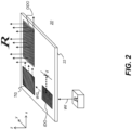
- FIG. 2 shows an imaging light guide 20 arranged as a known beam expander that provides beam expansion along x- and y-axes using an intermediate turning grating TG to redirect the light output (first diffracted mode) from in-coupling diffractive optic 110 to out-coupling diffractive optic 120.
- in-coupling diffractive optic 110 containing periodic rulings with a period d diffracts angularly related incoming input optical beams WI into the waveguide 22 as a set of angularly related beams WG, propagating by total internal reflection in an initial direction towards the intermediate turning grating TG.
- Intermediate grating TG is termed a "turning grating" because of its function in the optical path, redirecting the beams WG from within the waveguide 22 according to its grating vector in a direction towards the out-coupling diffractive optic 120, thereby accounting for a difference in angle between the grating vectors of the in-coupling diffraction optic 110 and the out-coupling diffraction optic 120.
- Intermediate grating TG which has angular orientation of diffraction elements and a spacing geometry determined by spacing period d, not only redirects the internally reflected beams WG but also contributes to beam expansion via multiple diffractive encounters with the light beams WG along the initial direction of propagation, i.e., along the y-axis in the view of FIG. 2 .
- the out-coupling diffractive optic 120 contributes to an orthogonal beam expansion via multiple diffractive encounters with the light beams WG along the redirected direction of propagation, i.e., along the x-axis in the view of FIG. 2 .
- the grating vectors generally designated k and shown with subscripts where they are specific to light within a color channel, extend parallel to the plane of the waveguide surface and are in the direction of the periodicity of the in-coupling and out-coupling diffractive optics 110 and 120, respectively.
- a turning grating TG placed at an intermediate position between the input and output couplings, such as the in-coupling and out-coupling diffractive optics 110 and 120, is typically chosen to minimize any changes on the encoded light.
- the pitch of the turning grating preferably matches the pitch of the in-coupling and out-coupling diffractive optics 110 and 120.
- the virtual image can be preserved by orienting the turning grating at around 60 degrees to in-coupling and out-coupling diffractive optics 110 and 120 in such a way that the encoded ray bundles are turned 120 degrees by one of the 1st reflection orders of the turning grating TG.
- the diffractive effects of the turning grating TG are most pronounced on the vector component of the incoming rays that are parallel to the grating vector of the turning grating.
- Turning gratings so arranged redirect ray bundles within the guide substrate while minimizing any changes to the encoded angular information of the virtual image.
- the resultant virtual image in such a designed system is not rotated. If such a system did introduce any rotation to the virtual image, the rotational effects could be non-uniformly distributed across different field angles and wavelengths of light, thus causing unwanted distortions or chromatic aberrations in the resultant virtual image.
- grating TG as envisioned for certain examples described herein preserves an inherent geometrical accuracy to the design of the light guide 20 so that the input beam and output beam are symmetrically oriented with respect to each other.
- grating vectors k direct the light from the in-coupling diffractive optic 110 to the out-coupling diffractive optic 120.
- the image that is formed for the imaging light guide viewer is a virtual image, focused at infinity or at least well in front of the light guide 20, but with the relative orientation of output image content to input image content preserved.
- a change in the rotation about the z axis or angular orientation of incoming light beams WI with respect to the x-y plane can cause a corresponding symmetric change in rotation or angular orientation of outgoing light from out-coupling diffractive optic (ODO) 120.
- turning grating TG is intended to function as a type of optical relay, providing expansion along one axis of the image that is input through the in-coupling diffractive optic (IDO) 110 and redirected to out-coupling diffractive optic (ODO) 120.
- Turning grating TG is typically a slanted or square grating or, alternately, can be a blazed grating. Reflective surfaces can alternately be used for turning the light toward the out-coupling diffractive optic 120.
- Beam expansion in two different dimensions is provided when using the arrangement of FIG. 2 .
- Turning grating TG expands the diffracted beam from in-coupling diffractive optic 110 in the y direction as shown.
- Out-coupling diffractive optic 120 further expands the diffracted beam in the x direction, orthogonal to the y direction as shown.
- the known imaging light guide 20 that is shown in FIG. 2 has been used in a number of existing head-mounted device (HMD) designs for providing image content to a viewer.
- This type of beam expander is particularly well-suited to augmented reality applications in which image content can be superimposed on a real-world view as seen through the transparent imaging light guide.
- Angular performance of the turning gratings can be limiting.
- the turning gratings when designed correctly, can at best be an ideal solution for a single field angle and at a single wavelength.
- the efficiency curve for the reflective refractive order that actually redirects the light has similar characteristics to those for the in-coupling and out-coupling diffractive optics.
- a ray of the design wavelength and at a central field angle propagating through the system is efficiently in-coupled (diffractive optic IDO), efficiently turned and expanded in one dimension (grating TG), and efficiently out-coupled and expanded in the orthogonal dimension (diffractive optic ODO).
- a similar ray of the same wavelength, but from an extreme field point, would conversely be less efficiently coupled in, less efficiently turned, and less efficiently coupled out. This leads to difficulty in balancing performance, color balance, and brightness across the full angular field.
- Conventional hand-held projection devices such as pico-projectors for example, typically provide image content with a 9:16 height-to-width aspect ratio.
- Angular range limitations of the conventional imaging light guide design constrain the allowed orientation of projector devices, typically preventing compact packaging of pico-projector devices in an HMD, for example.
- overall light efficiency is limited, as was noted previously.
- Embodiments of the present disclosure provide an optical system for forming a virtual image with an enlarged view pupil or eyebox.
- the optical system includes an imaging light guide in the form of a single planar waveguide component that has (i) an in-coupling element, such as an in-coupling diffractive optic IDO, for accepting incident image-bearing light beams and directing at least the first order diffracted light from the incident light beams along the planar component using TIR; (ii) an out-coupling element, such as an out-coupling diffractive optic ODO, for expanding the respective image-bearing light beams in a first direction transverse to the direction of beam propagation and directing the image-bearing light beams outward to form the virtual image; and (iii) a reflector array having at least first and second parallel reflective surfaces, differing from each other in reflectivity, that expand the respective image-bearing light beams in a second direction transverse to the direction of beam propagation and orthogonal to the first direction and are disposed
- FIG. 3 shows a light guide 30 arranged as a beam expander on a waveguide substrate S that uses a reflector 36 for turning the output beams.
- Reflector 36 is formed within or along an outer edge of the waveguide substrate S, disposed at an appropriate angle for the grating vectors in the direction of the periodicity of the in-coupling and out-coupling diffractive optics IDO and ODO, respectively.
- reflector 36 reflects light that is parallel to the grating vector of in-coupling diffractive optic IDO so that the reflected light is, in turn, parallel to the grating vector of out-coupling diffractive optic ODO.
- Dashed lines show light paths for the diffracted first order light within the imaging light guide. As the dashed lines indicate, reflector 36 changes the orientation of the virtual image, effectively reversing the virtual image content and rotating the image at twice the incident angle of the central field chief ray at the reflector, as shown by the letter 'R' in this figure.
- pupil expansion is effected in one direction only in the FIG. 3 arrangement using the out-coupling diffractive optic ODO.
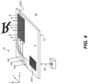
- FIG. 4 is a perspective view that shows an imaging light guide 30 arranged as beam expander according to a comparative example of the present disclosure.
- Light guide 30 has in-coupling and out-coupling diffractive optics IDO and ODO respectively, as described with reference to FIGS. 2 and 3 and uses a reflector array 32 for 2-dimensional (2-D) beam expansion.
- An arrangement of this type expands the light beam output in the x and y directions.
- Reflector array 32 has three specularly reflective surfaces, shown in the FIG. 4 embodiment as reflectors 34a, 34b, and 34c.
- Some of the specularly reflective surfaces in the array are partially reflective, so that some of the light incident on reflector 34a is transmitted through to reflector 34b; similarly, some of the light incident on reflector 34b is transmitted through to reflector 34c. Reflectivity increases for successive reflectors in the array as the reflectors are further separated from the in-coupling or out-coupling diffractive optics IDO, ODO.
- the last or rearmost reflector in the series, reflector 34c in the example of FIG. 4 generally has a nominal reflectance of 100%.
- the successive reflectors 34a, 34b, and 34c of reflector array 32 can have different amounts of reflectivity or, conversely, different amounts of transmittance.
- Exemplary values for a 5-reflector embodiment, with no absorption, are given in the following table. Table. Exemplary Reflectivity for 5-Reflector Array Reflector Reflectivity Transmissivity 1 12% 88% 2 16% 84% 3 23% 77% 4 38% 62% 5 100% ---
- FIG. 5A is a plan view of an imaging light guide 40 arranged as a beam expander that traces the axial light paths for central field points from in-coupling diffractive optic IDO to out-coupling diffractive optic ODO when using reflector array 32.
- reflector array 32 has four reflective surfaces, shown as reflectors 34a, 34b, 34c, and 34d.
- beam expansion takes place not only due to the reflections of light transmitted to the reflectors 34a, 34b, 34c, and 34d, but also because portions of the reflected light are further reflected by the reflectors 34a, 34b, 34c, and 34d .
- the same light can encounter the same individual reflectors 34a, 34b, 34c, and 34d multiple times under conditions of transmission or reflection. Some of this multiple reflection is shown.
- reflectors 34a, 34b, and 34c are reflective on both sides, so that diminishing portions of the light propagate between each combination of parallel reflective surfaces. The reflectivity designated for each of the respective surfaces accounts for these additional reflections. It can also be noted that there will be some inevitable losses due to absorption as well as due to light propagation beyond the reflectors themselves or the target output grating area.
- the spacing between the reflective surfaces of reflectors 34a, 34b, 34c, and 34d is another consideration for maintaining the desired intensity profile throughout each of the expanded beams. For example, one would not want to split an individual (pixel) beam into beamlets that are deflected beyond a region of proximate overlap with adjacent beamlets to avoid gaps or brightness variations in the image viewable within the eyebox. Proper reflectivity and spacing between reflective surfaces can also produce a desired distribution of energy across the expanded individual (pixel) beam composed of the multiple beamlets. In general, the distance between reflector surfaces should not exceed about 2.5 times the thickness of the guide substrate S
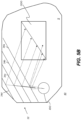
- FIG. 5B is a plan view of an imaging light guide 40 arranged as a beam expander that is modified to show redirection of field points spaced away from the central field point, with light at normal incidence. The same angular incidence of the light applies for each of reflectors 34a, 34b, 34c, and 34d.
- FIG. 6A shows an alternate comparative example of an imaging light guide 50 arranged as a beam expander using imaging light guide 22 that provides variable amounts of reflectance using only two reflectors 44a and 44b in a box arrangement provided by a gradient reflector array 42.
- Reflector 44b is a standard mirror with a nominal reflectance for visible light of 100%.
- Reflector 44a has a gradient coating with varying reflectance along its length, distributing reflected light internal to reflector array 42 in order to provide beam expansion.
- the phrase "gradient reflectivity" indicates that the reflectivity value changes progressively, preferably in a continuously increasing or decreasing manner, but can also include more incremental changes in reflectivity as may be preferable for purposes of manufacture or optical performance.
- the gradient reflectivity over a length portion of the reflector 44a continuously changes monotonically over a range from less than 10% reflectivity to greater than 50% reflectivity. Other ranges can also be provided.
- FIG. 6B is a schematic view, selectively omitting some of the imaging light guide 22 detail of FIG. 6A for clarity, showing how gradient reflector array 42 operates, repeatedly reflecting the light from in-coupling diffractive optic IDO with variably transmissive regions arranged in succession.
- Diffracted light output from in-coupling diffractive optic IDO initially passes through a fully transmissive region 46a of reflector 44a and is reflected by reflector 44b, which directs the light back toward reflector 44a.
- a partially transmissive region 46b of reflector 44a is coated to provide a reflective gradient, by way of example, ranging from 75% reflective to less than 50% reflective along the length of reflector 44a.
- the light that is transmitted through reflector 44a is directed outward toward out-coupling diffractive optic ODO.
- Reflector 44b reflects the incident light that had been reflected from region 46b back toward partially transmissive region 46b, over a segment of reflector 44a that is less reflective, such as 66% reflective in this example. Over the portion of reflector 44a that is 66% reflective, about 1/3 of incident light is then transmitted to another portion of out-coupling diffractive optic ODO. A diminishing amount of light is repeatedly reflected back and forth between reflectors 44a and 44b until a final remnant of the image-bearing light from in-coupling diffractive optic IDO is transmitted to diffractive optic ODO through gradient reflector 44a.
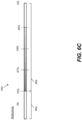
- FIG. 6C shows an overall arrangement of regions 46a and 46b of gradient reflector 44a in side view in FIG. 6C . Dashed lines indicate local values of reflectivity along gradient reflector 44a.
- FIG. 6D shows an imaging light guide 60 arranged as a beam expander in a perspective view. Reflector 44b is formed along an edge of imaging light guide 22 in the example shown. It can be readily appreciated that reflectivity values given herein for the FIG. 6A-6D examples illustrate the general principle for varying the reflectivity of gradient reflector 44a but are not to be considered restrictive. The reflectivity values that are actually used in any embodiment can depend on various factors including amount of light loss, coatings tolerances, and other performance variables. Subregions having uniform reflectivity values, changing along the length of reflector 44a, could alternatively be provided.
- the gradient reflectivity of reflector array 42 can provide an additional freedom sensitive to inclination angle. While simply expanding the individual (pixel) beams helps to expand the eyebox, the typical eyebox remains much smaller than the size of the individual expanded beams because the expanded beams do not fully intersect at the eyebox. In order to more fully intersect at the eyebox, the individual beams, which propagate in different directions, must exit from different positions within the output grating. To improve the chances of intersection (i.e., overlap) in one dimension, certain angle beams can be directed more toward one side of the output grating than the other. To cause this, the gradient reflective surface can be made selectively more reflective to light of certain angles of incidence over other angles of incidence so that the different angles are directed toward different sides of the output grating. Using this method is complicated by the individual (pixel) beams being angularly encoded in two dimensions. Thus, the reflective sensitivity should be limited to just one of the dimensions.
- the beam expander optics would provide each individual (pixel) beam with its own transverse distribution of energy so that most of the energy reaches the eyebox and nonoverlapping portions of the beams contain less energy.
- the reflective surfaces of arrays 32 and 42 construct the output individual (pixel) beams as individual collections of relatively offset beamlets, where each beamlet can vary in both intensity and position.
- Embodiments of the present disclosure allow the reflective intermediate beam expander to direct light toward out-coupling diffractive optic ODO through a range of angles spanning at least 90 degrees. The light can approach out-coupling diffractive optic ODO along either orthogonal axis of the image or somewhere in-between, such as at an oblique angle as shown in FIG. 5A .
- the reflector arrays 32, 42 can provide for interconnecting the central field rays between the in-coupling and out-coupling diffractive optics IDO, ODO at oblique angles while maintaining alignment with one of the orthogonal axes x, y of the image, particularly at the out-coupling diffractive optic.
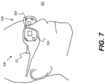
- FIG. 7 shows a display system 60 for three-dimensional (3-D) augmented reality viewing using imaging light guides of the present disclosure.
- Display system 60 is shown as an HMD with a left-eye optical system 54I having an imaging waveguide 50I arranged as a beam expander for the left eye and a corresponding right-eye optical system 54r having an imaging light guide 50r arranged as a beam expander for the right eye.
- An image source 52 such as a pico-projector or similar device, can be provided, energizable to generate a separate image for each eye, formed as a virtual image with the needed image orientation for upright image display, as described previously.
- the images that are generated can be a stereoscopic pair of images for 3-D viewing.
- the virtual image that is formed by the optical system can appear to be superimposed or overlaid onto the real-world scene content seen by the viewer.
- Additional components familiar to those skilled in the augmented reality visualization arts, such as one or more cameras mounted on the frame of the HMD for viewing scene content or viewer gaze tracking, can also be provided.
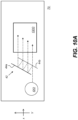
- FIG. 8 shows an alternative comparative example of imaging light guide 22 using gradient reflector array 42.
- in-coupling diffractive optic IDO is positioned more closely toward 100% reflective reflector 44b than in other examples and is in line with gradient reflective reflector 44a; a line L1 coincident with gradient reflective reflector 44a intersects in-coupling diffractive optic IDO.
- Reflectors 44a and 44b are at 45 degrees to the k vector or grating vector, which extends in the direction of periodicity, for in-coupling diffractive optic IDO.
- Embodiments described herein use diffractive optics for in-coupling and out-coupling functions, and used for conventional waveguides. It must be noted that input and output coupling can use mechanisms other than diffraction, such as reflection, for example, for directing angularly encoded beams into and out from the imaging waveguide and providing the desired beam expansion.
- Reflectors that form the reflector array 32 or gradient reflector array 42 can be formed using dichroic coatings, metalized coatings, or a combination of dichroic and metalized coatings.
- methods for forming reflector array 32 can include coating individual pieces of glass or other transparent substrate, then piecing together these portions to form the beam expander in sections.
- the imaging light guides are preferably manufactured in lots.
- the parallel surfaces perpendicular to the outer surfaces of the imaging light guide) can be cut and polished first.
- the blocks can be the thickness of multiple imaging light guides, which can then be coated and assembled, ideally, using index-matched adhesive. This assembly process can be performed under an autocollimator or with a retro-reflected spot to maintain proper alignment.
- Angular alignment precision can be on the order of 1 ⁇ 4 of the angular spread of one virtual image pixel. Achieving even finer resolution could require more accurate manufacturing practices.
- the block of aligned surfaces can be diced in a direction perpendicular to these surfaces to define the outer surfaces of the imaging light guides.
- Each block of glass can then be polished as a high quality flat under a double planetary polisher to form a blank.
- the polished blank preferably has better than one arc minute of parallelism.
- the final outer shape of the imaging light guide can be cut from a blank in an appropriate manner.
- the diffractive optics can be formed on one or both outer surfaces of the imaging light guide using nano-imprinting methods, for example.
- the imaging light guide can be formed with a flat substrate such as an optical glass, as described with reference to an embodiment of the present disclosure.
- a flat substrate such as an optical glass
- embodiments of the present disclosure provide an imaging light guide formed in a flat waveguide and having an in-coupling diffractive optic formed on the substrate that is disposed to form first-order diffracted light from each incident light beam representing a pixel of the virtual image and an array of two or more reflective surfaces disposed in parallel along or within the substrate and wherein at least one of the two or more reflective surfaces lies in the path of first-order diffracted light formed from the in-coupling diffractive optic.
- the two or more reflective surfaces are disposed at an angle that directs the first-order diffracted light formed from the in-coupling diffractive optic towards an out-coupling diffractive optic that is disposed to direct light outward from the imaging light guide.
- the out-coupling diffractive optic and the in-coupling diffractive optic preferably have the same grating period and each of the two or more reflective surfaces has a different reflectivity.
- a light guide in the form of a beam expander that provides an output image that has the same orientation as the input image that is provided in incoming light beam WI.
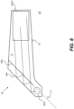
- a beam expander having a reduced height There can be advantages to a beam expander having a reduced height.
- the perspective view of Fig. 9 and plan view schematic of Fig. 10A show a light guide 70 arranged as a beam expander that uses gradient mirror array 42 in order to provide these advantages.
- Image-bearing light beams from in-coupling diffraction optic IDO are directed to gradient mirror array 42 generally along the direction of its grating vector k.
- Gradient mirror array 42 expands the light beams in the y direction in the coordinate system that is shown and directs the expanded light beams to out-coupling diffraction optic ODO.
- Out-coupling diffraction optic ODO has the same grating direction (i.e., is in parallel) as in-coupling diffraction optic IDO.
- grating vectors k and k1 for the in-coupling and out-coupling diffraction optics, respectively, are likewise in parallel.
- the light path through gradient mirror array 42 directs the light so that a first portion of each the image-bearing light beam is transmitted directly through the reflector array and the balance of the image-bearing light of each beam is reflected an even number of times (2 reflections, 4 reflections, 6 reflections, etc.) by the two or more at least partially reflective surfaces 44a, 44b, 44c of mirror array 42.
- Figs. 10A and 10B show gradient mirror array 42 disposed at different oblique angles relative to out-coupling diffraction optic ODO, based on the relative position of in-coupling diffraction optic IDO.
- Fig. 10C shows mirror array 42 having more than two reflective surfaces 44a, 44b, 44c for expanding the image-bearing light beam in the y-axis dimension. Out-coupling diffraction optic ODO then expands the image-bearing light with respect to the x-axis dimension.
Claims (15)
- Bildgebender Lichtleiter (30, 40, 50, 60) zum Übertragen eines virtuellen Bildes, umfassend:einen Wellenleiter (22);eine einkoppelnde diffraktive Optik (IDO) mit einem ersten Gittervektor (k), die so angeordnet ist, dass sie bildtragende Lichtstrahlen in den Wellenleiter (22) lenkt; undeine Reflektoranordnung (42) aus zwei oder mehr zumindest teilweise reflektierenden Oberflächen (44a, 44b, 44c), die parallel ausgerichtet und so angeordnet sind, dass sie die jeweiligen bildtragenden Lichtstrahlen von der einkoppelnden diffraktiven Optik (IDO) in einer ersten Dimension aufweiten und die aufgeweiteten bildtragenden Lichtstrahlen auf eine auskoppelnde diffraktive Optik (ODO) richten;wobei die mindestens zwei oder mehr zumindest teilweise reflektierenden Oberflächen spiegelnd reflektierend sind; undwobei die auskoppelnde Beugungsoptik (ODO) einen zweiten Gittervektor (k1) parallel zum ersten Gittervektor (k) aufweist und so angeordnet ist, dass sie die bildtragenden Lichtstrahlen aus der Reflektoranordnung in einer zweiten Dimension orthogonal zur ersten Dimension aufweitet und die bildtragenden Lichtstrahlen aus dem Wellenleiter (22) auf eine Eyebox richtet.
- Bildgebender Lichtleiter nach Anspruch 1, wobei die zwei oder mehr zumindest teilweise reflektierenden Oberflächen der Reflektoranordnung (42) eine erste und eine zweite Oberfläche umfassen, wobei die erste Oberfläche teilweise reflektierend und teilweise durchlässig ist und die zweite Oberfläche vollständig reflektierend ist.
- Bildgebender Lichtleiter nach Anspruch 2, wobei die erste Oberfläche eine Länge und Reflexionswerte aufweist, die entlang mindestens eines Teils der Länge variieren, wobei die Reflexionswerte der ersten Oberfläche vorzugsweise monoton entlang der Länge von weniger als 10 % Reflexionsgrad bis zu mehr als 50 % Reflexionsgrad variieren.
- Bildgebender Lichtleiter nach einem der Ansprüche 1 bis 3, wobei mindestens eine der einkoppelnden diffraktiven Optik (IDO) und der auskoppelnden diffraktiven Optik (ODO) ein Beugungsgitter oder ein Volumenhologramm ist oder aus einem holografischen, in einem Polymer dispergierten Flüssigkristall gebildet wird.
- Bildgebender Lichtleiter nach Anspruch 1, wobei ein erster Teil des bildtragenden Lichtstrahls direkt durch die Reflektoranordnung (42) übertragen wird und der Rest des bildtragenden Lichts eine gerade Anzahl von Malen von den zwei oder mehr zumindest teilweise reflektierenden Oberflächen (44a, 44b, 44c) reflektiert wird.
- Bildgebender Lichtleiter nach einem der Ansprüche 1 bis 5, wobei eine oder mehrere der zumindest teilweise reflektierenden Oberflächen (44a, 44b, 44c) unter Verwendung dichroitischer Beschichtungen ausgebildet sind.
- Bildgebender Lichtleiter nach einem der Ansprüche 2 bis 6, wobei die zwei oder mehr zumindest teilweise reflektierenden Oberflächen (44a, 44b, 44c) der Reflektoranordnung (42) ferner eine dritte Oberfläche (44b) umfassen, wobei die dritte Oberfläche (44b) zwischen der ersten (44a) und der zweiten (44c) Oberfläche angeordnet ist, die dritte Oberfläche (44b) teilweise reflektierend und teilweise durchlässig ist und die dritte Oberfläche (44b) einen Reflexionswert aufweist, der größer ist als ein Reflexionswert der ersten Oberfläche (44a).
- Bildgebender Lichtleiter nach einem der Ansprüche 1 bis 7, wobei die Reflektoranordnung (42) so positioniert ist, dass sie zentrale Feldstrahlen des virtuellen Bildes zwischen der einkoppelnden diffraktiven Optik (IDO) und der auskoppelnden diffraktiven Optik (ODO) in einem schrägen Winkel reflektiert.
- Bildgebender Lichtleiter nach Anspruch 1,wobei die mindestens zwei oder mehr zumindest teilweise reflektierenden Oberflächen erste und zweite zumindest teilweise reflektierende Oberflächen (44a, 44b) umfassen, die entlang oder innerhalb des Wellenleiters (22) angeordnet sind, undwobei die erste zumindest teilweise reflektierende Oberfläche (44b) teilweise reflektierend und teilweise durchlässig ist, die zweite zumindest teilweise reflektierende Oberfläche (44a) stärker reflektierend ist als die erste zumindest teilweise reflektierende Oberfläche (44b) und die erste zumindest teilweise reflektierende Oberfläche (44b) angeordnet ist(a) um Teile der bildtragenden Lichtstrahlen, die von der zweiten, zumindest teilweise reflektierenden Oberfläche (44a) reflektiert werden, zurück zu der zweiten, zumindest teilweise reflektierenden Oberfläche (44a) zu reflektieren, und(b) um Teile der bildtragenden Lichtstrahlen, die von der zweiten, zumindest teilweise reflektierenden Oberfläche (44a) reflektiert werden, in Richtung der auskoppelnden diffraktiven Optik (ODO) zu übertragen.
- Bildgebender Lichtleiter nach Anspruch 9, wobei die erste zumindest teilweise reflektierende Oberfläche (44b) eine Länge und Reflektivitätswerte aufweist, die entlang zumindest eines Teils der Länge variieren, wobei die unterschiedlichen Reflektivitätswerte der ersten zumindest teilweise reflektierenden Oberfläche (44b) vorzugsweise über einen Gradienten von weniger als 10% Reflektivität bis zu mehr als 50% Reflektivität reichen.
- Bildgebender Lichtleiter nach Anspruch 9 oder 10, wobei die erste und die zweite zumindest teilweise reflektierende Oberfläche (44a, 44b) relativ zueinander so angeordnet sind, dass sie zentrale Feldstrahlen des virtuellen Bildes zwischen der einkoppelnden diffraktiven Optik (IDO) und der auskoppelnden diffraktiven Optik (ODO) in einem schrägen Winkel reflektieren.
- Bildgebender Lichtleiter nach einem der Ansprüche 9 bis 11, wobei die erste und die zweite, zumindest teilweise reflektierende Oberfläche (44a, 44b) um eine begrenzte Strecke voneinander beabstandet sind, in der sich Teile der bildtragenden Lichtstrahlen auf dem Weg zur auskoppelnden Beugungsoptik zumindest annähernd überlappen.
- Verfahren zur Herstellung eines bildgebenden Lichtleiters, umfassend:a) Bilden einer einkoppelnden diffraktiven Optik (IDO) auf einem planaren Substrat, wobei die einkoppelnde diffraktive Optik (IDO) eine erste Gitterperiode und einen ersten Gittervektor aufweist;b) Bilden einer auskoppelnden Beugungsoptik (ODO) auf dem planaren Substrat, wobei die auskoppelnde Beugungsoptik (ODO) eine zweite Gitterperiode, die gleich der ersten Gitterperiode ist, und einen zweiten Gittervektor aufweist, der parallel zu dem ersten Gittervektor ist; undc) Bilden einer Reflektoranordnung (42) entlang oder innerhalb des planaren Substrats, die so angeordnet ist, dass sie gebeugtes Licht von der einkoppelnden diffraktiven Optik (IDO) zur auskoppelnden diffraktiven Optik (ODO) leitet,wobei die Reflektoranordnung (42) zwei oder mehr zumindest teilweise reflektierende Oberflächen (44a, 44b) umfasst, die parallel ausgerichtet sind, wobei jede der zwei oder mehr zumindest teilweise reflektierenden Oberflächen (44a, 44b) ein unterschiedliches Reflexionsvermögen aufweist; undwobei die mindestens zwei oder mehr zumindest teilweise reflektierenden Oberflächen (44a, 44b) spiegelnd reflektierend sind.
- Verfahren nach Anspruch 13, wobei der Schritt des Bildens der einkoppelnden diffraktiven Optik (IDO) das Anordnen der einkoppelnden diffraktiven Optik (IDO) umfasst, um einfallende bildtragende Lichtstrahlen in das planare Substrat zur Ausbreitung innerhalb des Substrats in Richtung der Reflektoranordnung (42) zu beugen, der Schritt des Bildens der auskoppelnden diffraktiven Optik (ODO) das Anordnen der auskoppelnden diffraktiven Optik (ODO) umfasst, um einfallende bildtragende Lichtstrahlen, die von der Reflektoranordnung (42) reflektiert werden, aus dem planaren Substrat zur Betrachtung als ein virtuelles Bild zu beugen, und der Schritt des Bildens der Reflektoranordnung (42) das Anordnen der Reflektoranordnung (42) umfasst, um die bildtragenden Lichtstrahlen von der einkoppelnden diffraktiven Optik (IDO) in einer ersten Dimension aufzuweiten.
- Verfahren nach Anspruch 13 oder 14, wobei der Schritt des Bildens der auskoppelnden diffraktiven Optik (ODO) das Anordnen der auskoppelnden diffraktiven Optik (ODO) umfasst, um die bildtragenden Lichtstrahlen von der Reflektoranordnung (42) in einer zweiten Dimension orthogonal zu der ersten Dimension aufzuweiten, und die Schritte des Bildens der einkoppelnden diffraktiven Optik (IDO), der auskoppelnden diffraktiven Optik (ODO) und der Reflektoranordnung (42) das relative Positionieren der Reflektoranordnung (42) zum Reflektieren zentraler Feldstrahlen des virtuellen Bildes zwischen der einkoppelnden diffraktiven Optik (IDO) und der auskoppelnden diffraktiven Optik (ODO) über einen schrägen Winkel einschließt.
Applications Claiming Priority (2)
| Application Number | Priority Date | Filing Date | Title |
|---|---|---|---|
| US201662275552P | 2016-01-06 | 2016-01-06 | |
| PCT/US2017/012319 WO2017120326A1 (en) | 2016-01-06 | 2017-01-05 | Imaging light guide with reflective turning array |
Publications (3)
| Publication Number | Publication Date |
|---|---|
| EP3400477A1 EP3400477A1 (de) | 2018-11-14 |
| EP3400477A4 EP3400477A4 (de) | 2020-01-08 |
| EP3400477B1 true EP3400477B1 (de) | 2023-10-25 |
Family
ID=59274527
Family Applications (1)
| Application Number | Title | Priority Date | Filing Date |
|---|---|---|---|
| EP17736326.4A Active EP3400477B1 (de) | 2016-01-06 | 2017-01-05 | Abbildungslichtleiter mit reflektierender drehanordnung |
Country Status (5)
| Country | Link |
|---|---|
| US (1) | US11598970B2 (de) |
| EP (1) | EP3400477B1 (de) |
| JP (1) | JP6720315B2 (de) |
| CN (1) | CN109073909B (de) |
| WO (1) | WO2017120326A1 (de) |
Families Citing this family (14)
| Publication number | Priority date | Publication date | Assignee | Title |
|---|---|---|---|---|
| US10551544B2 (en) * | 2018-01-21 | 2020-02-04 | Lumus Ltd. | Light-guide optical element with multiple-axis internal aperture expansion |
| FI128552B (en) * | 2018-03-28 | 2020-07-31 | Dispelix Oy | Wavelength display element with reflector surface |
| WO2019224764A1 (en) | 2018-05-23 | 2019-11-28 | Lumus Ltd. | Optical system including light-guide optical element with partially-reflective internal surfaces |
| US20210231854A1 (en) * | 2018-07-02 | 2021-07-29 | Vuzix Corporation | Waveguide turning grating designs for optimal efficiency |
| MX2021002813A (es) * | 2018-09-09 | 2021-05-12 | Lumus Ltd | Sistemas opticos que incluyen elementos opticos de guia de luz con expansion bidimensional. |
| US11221483B2 (en) * | 2018-12-10 | 2022-01-11 | Auroratech Company | Optical system for AR headsets, and method for design and manufacturing |
| JP7416807B2 (ja) * | 2019-01-14 | 2024-01-17 | ビュージックス コーポレーション | 大きな回折格子パターンのデジタル書き込み |
| CN113050276A (zh) * | 2019-12-27 | 2021-06-29 | 华为技术有限公司 | 衍射图像叠加器、显示设备模组及头戴式显示设备 |
| CN111240015B (zh) * | 2020-01-17 | 2020-12-18 | 北京理工大学 | 双侧对射出光均匀的衍射波导 |
| CN112630969B (zh) * | 2020-12-24 | 2022-05-17 | 浙江大学 | 一种光栅波导显示装置 |
| CN115509006A (zh) * | 2021-06-23 | 2022-12-23 | 华为技术有限公司 | 光学设备及电子设备 |
| CN116068768A (zh) * | 2022-03-15 | 2023-05-05 | 嘉兴驭光光电科技有限公司 | 衍射光波导以及具有其的显示设备 |
| CN114967148B (zh) * | 2022-05-24 | 2023-11-17 | 歌尔光学科技有限公司 | 光波导器件和增强现实显示设备 |
| CN115877560B (zh) * | 2023-03-08 | 2023-06-16 | 杭州光粒科技有限公司 | 一种激光扫描成像模组及装置、ar显示设备 |
Citations (1)
| Publication number | Priority date | Publication date | Assignee | Title |
|---|---|---|---|---|
| EP3347761A1 (de) * | 2015-09-10 | 2018-07-18 | Vuzix Corporation | Abbildungslichtleiter mit reflektierender drehanordnung |
Family Cites Families (19)
| Publication number | Priority date | Publication date | Assignee | Title |
|---|---|---|---|---|
| WO2001095027A2 (en) * | 2000-06-05 | 2001-12-13 | Lumus Ltd. | Substrate-guided optical beam expander |
| US6891865B1 (en) | 2002-02-15 | 2005-05-10 | Afonics Fibreoptics, Ltd. | Wavelength tunable laser |
| IL148804A (en) | 2002-03-21 | 2007-02-11 | Yaacov Amitai | Optical device |
| IL157837A (en) | 2003-09-10 | 2012-12-31 | Yaakov Amitai | Substrate-guided optical device particularly for three-dimensional displays |
| US20060126181A1 (en) * | 2004-12-13 | 2006-06-15 | Nokia Corporation | Method and system for beam expansion in a display device |
| JP4567786B2 (ja) * | 2005-06-03 | 2010-10-20 | ノキア コーポレイション | 射出瞳を拡大する汎用的な回折的光学方法 |
| EP1952189B1 (de) | 2005-11-21 | 2016-06-01 | Microvision, Inc. | Display mit bildführendem substrat |
| JP2007219106A (ja) * | 2006-02-16 | 2007-08-30 | Konica Minolta Holdings Inc | 光束径拡大光学素子、映像表示装置およびヘッドマウントディスプレイ |
| WO2008148927A1 (en) * | 2007-06-04 | 2008-12-11 | Nokia Corporation | A diffractive beam expander and a virtual display based on a diffractive beam expander |
| EP2030568A1 (de) | 2007-08-28 | 2009-03-04 | Roche Diagnostics GmbH | Stechsystem |
| US8508848B2 (en) | 2007-12-18 | 2013-08-13 | Nokia Corporation | Exit pupil expanders with wide field-of-view |
| PL2242419T3 (pl) * | 2008-02-14 | 2016-05-31 | Nokia Technologies Oy | Urządzenie i sposób określania kierunku spojrzenia |
| JP5344169B2 (ja) | 2008-09-30 | 2013-11-20 | 大日本印刷株式会社 | ホログラフィック高分子分散液晶光学素子及びホログラフィック高分子分散液晶光学素子の製造方法 |
| US8548290B2 (en) * | 2011-08-23 | 2013-10-01 | Vuzix Corporation | Dynamic apertured waveguide for near-eye display |
| US8736963B2 (en) | 2012-03-21 | 2014-05-27 | Microsoft Corporation | Two-dimensional exit-pupil expansion |
| CN102928981B (zh) * | 2012-11-14 | 2016-08-03 | 中航华东光电有限公司 | 全息光波导头盔显示器光学系统 |
| WO2014188149A1 (en) * | 2013-05-20 | 2014-11-27 | Milan Momcilo Popovich | Holographic waveguide eye tracker |
| JP2015145973A (ja) | 2014-02-03 | 2015-08-13 | セイコーエプソン株式会社 | 虚像表示装置および光学素子 |
| JP6314518B2 (ja) * | 2014-02-10 | 2018-04-25 | ソニー株式会社 | 画像表示装置及び表示装置 |
-
2017
- 2017-01-05 US US16/068,024 patent/US11598970B2/en active Active
- 2017-01-05 CN CN201780015386.5A patent/CN109073909B/zh active Active
- 2017-01-05 EP EP17736326.4A patent/EP3400477B1/de active Active
- 2017-01-05 JP JP2018533875A patent/JP6720315B2/ja active Active
- 2017-01-05 WO PCT/US2017/012319 patent/WO2017120326A1/en active Application Filing
Patent Citations (1)
| Publication number | Priority date | Publication date | Assignee | Title |
|---|---|---|---|---|
| EP3347761A1 (de) * | 2015-09-10 | 2018-07-18 | Vuzix Corporation | Abbildungslichtleiter mit reflektierender drehanordnung |
Also Published As
| Publication number | Publication date |
|---|---|
| JP6720315B2 (ja) | 2020-07-08 |
| EP3400477A4 (de) | 2020-01-08 |
| WO2017120326A1 (en) | 2017-07-13 |
| US11598970B2 (en) | 2023-03-07 |
| CN109073909B (zh) | 2021-10-08 |
| CN109073909A (zh) | 2018-12-21 |
| JP2019507370A (ja) | 2019-03-14 |
| EP3400477A1 (de) | 2018-11-14 |
| US20210215941A1 (en) | 2021-07-15 |
Similar Documents
| Publication | Publication Date | Title |
|---|---|---|
| EP3347761B1 (de) | Abbildungslichtleiter mit reflektierender drehanordnung | |
| EP3400477B1 (de) | Abbildungslichtleiter mit reflektierender drehanordnung | |
| EP3916465B1 (de) | Festfokusbildlichtleiter mit zonierten beugungsgittern | |
| CN112867959B (zh) | 用于最优效率的波导转向光栅设计 | |
| WO2017120346A1 (en) | Head-mounted display with pivoting imaging light guide | |
| US20230213770A1 (en) | Image light guide with zoned diffractive optic | |
| US20230417974A1 (en) | Image light guide with zoned diffractive optic | |
| WO2023220133A1 (en) | Dual index waveguide stack | |
| US20230341685A1 (en) | Dual input imaging light guide | |
| US20240094456A1 (en) | Image light guide with compound in-coupling diffractive optic | |
| WO2023091685A1 (en) | Image light guide having high-index outer layers | |
| WO2024006638A1 (en) | Multiplexing image light guide with split input and optical power | |
| WO2023192650A1 (en) | Multiple wavelength range imaging light guide system | |
| WO2023225368A1 (en) | Image light guide system with crossed in-coupling optics | |
| WO2022187664A1 (en) | Image light guide with multi-wavelength in-coupling diffractive optic |
Legal Events
| Date | Code | Title | Description |
|---|---|---|---|
| STAA | Information on the status of an ep patent application or granted ep patent |
Free format text: STATUS: THE INTERNATIONAL PUBLICATION HAS BEEN MADE |
|
| PUAI | Public reference made under article 153(3) epc to a published international application that has entered the european phase |
Free format text: ORIGINAL CODE: 0009012 |
|
| STAA | Information on the status of an ep patent application or granted ep patent |
Free format text: STATUS: REQUEST FOR EXAMINATION WAS MADE |
|
| 17P | Request for examination filed |
Effective date: 20180621 |
|
| AK | Designated contracting states |
Kind code of ref document: A1 Designated state(s): AL AT BE BG CH CY CZ DE DK EE ES FI FR GB GR HR HU IE IS IT LI LT LU LV MC MK MT NL NO PL PT RO RS SE SI SK SM TR |
|
| AX | Request for extension of the european patent |
Extension state: BA ME |
|
| DAV | Request for validation of the european patent (deleted) | ||
| DAX | Request for extension of the european patent (deleted) | ||
| STAA | Information on the status of an ep patent application or granted ep patent |
Free format text: STATUS: REQUEST FOR EXAMINATION WAS MADE |
|
| RIC1 | Information provided on ipc code assigned before grant |
Ipc: G02B 27/40 20060101ALI20190808BHEP Ipc: G02B 6/122 20060101ALI20190808BHEP Ipc: G02B 27/42 20060101AFI20190808BHEP |
|
| A4 | Supplementary search report drawn up and despatched |
Effective date: 20191211 |
|
| RIC1 | Information provided on ipc code assigned before grant |
Ipc: G02B 27/40 20060101ALI20191205BHEP Ipc: G02B 27/42 20060101AFI20191205BHEP Ipc: G02B 6/122 20060101ALI20191205BHEP |
|
| STAA | Information on the status of an ep patent application or granted ep patent |
Free format text: STATUS: EXAMINATION IS IN PROGRESS |
|
| 17Q | First examination report despatched |
Effective date: 20220801 |
|
| GRAP | Despatch of communication of intention to grant a patent |
Free format text: ORIGINAL CODE: EPIDOSNIGR1 |
|
| STAA | Information on the status of an ep patent application or granted ep patent |
Free format text: STATUS: GRANT OF PATENT IS INTENDED |
|
| INTG | Intention to grant announced |
Effective date: 20230214 |
|
| GRAJ | Information related to disapproval of communication of intention to grant by the applicant or resumption of examination proceedings by the epo deleted |
Free format text: ORIGINAL CODE: EPIDOSDIGR1 |
|
| STAA | Information on the status of an ep patent application or granted ep patent |
Free format text: STATUS: EXAMINATION IS IN PROGRESS |
|
| GRAP | Despatch of communication of intention to grant a patent |
Free format text: ORIGINAL CODE: EPIDOSNIGR1 |
|
| STAA | Information on the status of an ep patent application or granted ep patent |
Free format text: STATUS: GRANT OF PATENT IS INTENDED |
|
| INTC | Intention to grant announced (deleted) | ||
| INTG | Intention to grant announced |
Effective date: 20230504 |
|
| P01 | Opt-out of the competence of the unified patent court (upc) registered |
Effective date: 20230530 |
|
| GRAS | Grant fee paid |
Free format text: ORIGINAL CODE: EPIDOSNIGR3 |
|
| GRAA | (expected) grant |
Free format text: ORIGINAL CODE: 0009210 |
|
| STAA | Information on the status of an ep patent application or granted ep patent |
Free format text: STATUS: THE PATENT HAS BEEN GRANTED |
|
| AK | Designated contracting states |
Kind code of ref document: B1 Designated state(s): AL AT BE BG CH CY CZ DE DK EE ES FI FR GB GR HR HU IE IS IT LI LT LU LV MC MK MT NL NO PL PT RO RS SE SI SK SM TR |
|
| REG | Reference to a national code |
Ref country code: GB Ref legal event code: FG4D |
|
| REG | Reference to a national code |
Ref country code: CH Ref legal event code: EP |
|
| REG | Reference to a national code |
Ref country code: DE Ref legal event code: R096 Ref document number: 602017075662 Country of ref document: DE |
|
| REG | Reference to a national code |
Ref country code: IE Ref legal event code: FG4D |
|
| REG | Reference to a national code |
Ref country code: LT Ref legal event code: MG9D |
|
| REG | Reference to a national code |
Ref country code: NL Ref legal event code: MP Effective date: 20231025 |
|
| REG | Reference to a national code |
Ref country code: AT Ref legal event code: MK05 Ref document number: 1625248 Country of ref document: AT Kind code of ref document: T Effective date: 20231025 |
|
| PG25 | Lapsed in a contracting state [announced via postgrant information from national office to epo] |
Ref country code: NL Free format text: LAPSE BECAUSE OF FAILURE TO SUBMIT A TRANSLATION OF THE DESCRIPTION OR TO PAY THE FEE WITHIN THE PRESCRIBED TIME-LIMIT Effective date: 20231025 |
|
| PG25 | Lapsed in a contracting state [announced via postgrant information from national office to epo] |
Ref country code: GR Free format text: LAPSE BECAUSE OF FAILURE TO SUBMIT A TRANSLATION OF THE DESCRIPTION OR TO PAY THE FEE WITHIN THE PRESCRIBED TIME-LIMIT Effective date: 20240126 |
|
| PG25 | Lapsed in a contracting state [announced via postgrant information from national office to epo] |
Ref country code: IS Free format text: LAPSE BECAUSE OF FAILURE TO SUBMIT A TRANSLATION OF THE DESCRIPTION OR TO PAY THE FEE WITHIN THE PRESCRIBED TIME-LIMIT Effective date: 20240225 |
|
| PG25 | Lapsed in a contracting state [announced via postgrant information from national office to epo] |
Ref country code: LT Free format text: LAPSE BECAUSE OF FAILURE TO SUBMIT A TRANSLATION OF THE DESCRIPTION OR TO PAY THE FEE WITHIN THE PRESCRIBED TIME-LIMIT Effective date: 20231025 |