EP3400178B1 - Systeme und verfahren für einen schnurhalter - Google Patents
Systeme und verfahren für einen schnurhalter Download PDFInfo
- Publication number
- EP3400178B1 EP3400178B1 EP17736262.1A EP17736262A EP3400178B1 EP 3400178 B1 EP3400178 B1 EP 3400178B1 EP 17736262 A EP17736262 A EP 17736262A EP 3400178 B1 EP3400178 B1 EP 3400178B1
- Authority
- EP
- European Patent Office
- Prior art keywords
- cover
- twist tie
- stretchable
- durometer
- shore
- Prior art date
- Legal status (The legal status is an assumption and is not a legal conclusion. Google has not performed a legal analysis and makes no representation as to the accuracy of the status listed.)
- Active
Links
Images


Classifications
-
- B—PERFORMING OPERATIONS; TRANSPORTING
- B65—CONVEYING; PACKING; STORING; HANDLING THIN OR FILAMENTARY MATERIAL
- B65D—CONTAINERS FOR STORAGE OR TRANSPORT OF ARTICLES OR MATERIALS, e.g. BAGS, BARRELS, BOTTLES, BOXES, CANS, CARTONS, CRATES, DRUMS, JARS, TANKS, HOPPERS, FORWARDING CONTAINERS; ACCESSORIES, CLOSURES, OR FITTINGS THEREFOR; PACKAGING ELEMENTS; PACKAGES
- B65D63/00—Flexible elongated elements, e.g. straps, for bundling or supporting articles
- B65D63/10—Non-metallic straps, tapes, or bands; Filamentary elements, e.g. strings, threads or wires; Joints between ends thereof
- B65D63/109—Application of elastics or like elements
-
- B—PERFORMING OPERATIONS; TRANSPORTING
- B65—CONVEYING; PACKING; STORING; HANDLING THIN OR FILAMENTARY MATERIAL
- B65B—MACHINES, APPARATUS OR DEVICES FOR, OR METHODS OF, PACKAGING ARTICLES OR MATERIALS; UNPACKING
- B65B13/00—Bundling articles
- B65B13/02—Applying and securing binding material around articles or groups of articles, e.g. using strings, wires, strips, bands or tapes
-
- B—PERFORMING OPERATIONS; TRANSPORTING
- B65—CONVEYING; PACKING; STORING; HANDLING THIN OR FILAMENTARY MATERIAL
- B65D—CONTAINERS FOR STORAGE OR TRANSPORT OF ARTICLES OR MATERIALS, e.g. BAGS, BARRELS, BOTTLES, BOXES, CANS, CARTONS, CRATES, DRUMS, JARS, TANKS, HOPPERS, FORWARDING CONTAINERS; ACCESSORIES, CLOSURES, OR FITTINGS THEREFOR; PACKAGING ELEMENTS; PACKAGES
- B65D63/00—Flexible elongated elements, e.g. straps, for bundling or supporting articles
- B65D63/10—Non-metallic straps, tapes, or bands; Filamentary elements, e.g. strings, threads or wires; Joints between ends thereof
- B65D63/12—Joints produced by deformation or tying of ends of elements
Definitions
- Twist ties may be used to secure and hold a variety of objects. It is desirable for users to mount twist ties, especially those with high-end performance characteristics, in a variety of temporary and more permanent configurations, so that objects may be secured in useful positions.
- WO 2014/152590 A1 discloses an apparatus including a body, the body including an attachment mechanism for mounting the body and a twist tie, the twist tie integrated with the body.
- US 2006/012199 A1 discloses a cable tie having a handle for transporting articles secured by the cable tie.
- the cable tie includes a shackle and a shackle lock, wherein the shackle is inserted into the shackle lock where it may be engaged thereby and held fixed reversibly or releasably, thereby holding an article encircled by the shackle.
- Handles can be formed in many shapes, and may have finger indentations for ease of carrying.
- Identification flags can be formed onto the handles or elsewhere on a cable tie for providing a location to identify the user, the article, etc.
- US 2015/225150 A1 teaches a cord management organizer for use with an electrical cord.
- the organizer includes an elongate body extending from a first end to a second end, a plug retention opening proximate the second end, and an enlarged body portion adjacent the first end.
- the enlarged body portion has a thickness greater than a corresponding thickness of the body at a central region that is located intermediate the plug retention opening and enlarged body portion.
- the enlarged body portion includes a passageway having a central axis that extends in an elongate direction towards the central region of the body.
- US 2006/075610 A1 teaches a securing device for securing at least one object for storage or transport.
- the securing device comprises an elongate bendable member having first and second ends.
- the elongate bendable member comprises at least one inelastically deformable component having load bearing capabilities and means for reinforcing the inelastically deformable component.
- the securing device further comprises a first loop provided at a first end of the elongate bendable member and a second loop provided at a second end of the elongate bendable member.
- the first and second loops are deformable and configured to receive a loop of the same or another securing device.
- the stretchable end includes an aperture.
- the stretchable end includes first and second opposing sides bounded by third and fourth opposing sides and the aperture is defined through the first and second sides, the first and second sides defining a round or oval profile of the stretchable end, and the third and fourth sides defining a rectangular profile of the stretchable end.
- the aperture is a narrow slit in the stretchable end. In one configuration, the aperture may stretch wider and longer than a starting shape.
- the stretchable end is made of Thermoplastic Elastomer (TPE) and has a durometer between 30 and 100 shore A.
- the stretchable end is overmolded on the twist tie.
- the stretchable end is designed to hold an object, and the aperture of the stretchable end is sized such that, to hold the object, the stretchable end stretches and, therefore, frictionally holds the object.
- the twist tie further includes an elongated piece of shape-retaining deformable material, a cover covering the shape-retaining deformable material along a length of the elongated piece, the cover and the shape-retaining deformable material being bonded along their length; and an outer cover covering the cover, the outer cover bonded to the cover.
- the cover has an interior surface, the cover being bonded to the elongated piece of shape-retaining deformable material along the entire interior surface of the cover.
- the cover has a durometer of greater than 50 shore A and the outer cover has a durometer of less than 50 shore A.
- the outer cover has ribs.
- the cover and outer cover are thermoplastic polymers.
- the outer cover is composed of a softer material than the cover.
- the twist tie has a gripping surface.
- the gripping surface includes outwardly extending ribs.
- the cover has a durometer of approximately 85 shore A and the outer cover has a durometer of approximately 15 shore A.
- the outer cover provides a high friction gripping surface for gripping objects or gripping the twist tie device when the device is twisted together.
- Twist tie with a stretchable end 100 includes a twist tie portion 105 and a stretchable end 110.
- Stretchable end 110 includes an aperture 120. Any length twist tie portion alternatively may be used.
- an end cap 115 At the end of the twist tie portion 105 is an end cap 115 which enhances the ability of the user to wrap and secure the twist tie 100.
- Twist tie with a stretchable end 100 is formed by molding stretchable end 110 around twist tie portion 105.
- Stretchable end 110 may be composed of a variety of materials including, but not limited to, plastics, rubbers, nylon, etc.
- the stretchable end 110 is composed of Thermoplastic Elastomer (TPE) having a 50 shore A durometer.
- the twist tie portion 105 is a Gear Tie TM twist tie, and it includes special proprieties improving its function.
- Gear Tie TM twist ties include a softer durometer outer plastic layer of having a durometer less than 50 shore A and having an inner plastic layer of a harder durometer of greater than 50 shore A.
- the inner layer is bonded to the wire, and the outer layer is bonded to the inner layer.
- the inner layer may be composed of high density polyethylene. An adherent may be used to bind the inner layer to the wire.
- the twist tie has a stretchable end 100, the twist tie portion has a softer outer layer of a durometer of less than 100 shore A.
- this outer durometer is less than 50 shore A.
- the twist tie portion may be passed through the aperture 120.
- this configuration may slightly compress the outer layer and result in a firmly held loop configuration.
- the aperture of stretchable end 110 may be sized to accommodate twist tie portion 100.
- the aperture may be made slightly smaller than the diameter of twist tie 100.
- the aperture of stretchable end 110 may include protrusions or teeth that may add to the grip of twist tie 100 as it is passed through the aperture.
- the twist tie portion 105 is formed first and the stretchable end 110 is overmolded on top of the twist tie portion 105.
- Figs. 2 and 3 show additional views of the twist tie 100.
- the profiles of the stretchable end 110 are generally that of an oval from the top and bottom and generally rectangular from the side view.
- the outer layer of the twist tie portion 105 is composed of TPE having a 50A shore durometer.
- the stretchable end 110 is composed of TPE having a 50A shore durometer.
- the twist tie portion 105 includes an inner wire that adds rigidity to the twist tie portion 105.
- the bonded nature of the twist tie portion 105 increases the rigidity.
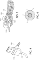
- the stretchable end 110 does not include any rigidity features and, therefore, may stretch to fit around objects and hold them firmly. Some examples of this are seen in Figs. 4 and 5 . In Fig.
- the stretchable end 110 stretches around a USB plug 410. Therefore, the twist tie 100 stays attached to the USB plug 410 in usage. When the USB plug 410 is no longer in use, the twist tie 100 that is attached to it by virtue of the stretchable end may then be used to wrap around and secure the cord.
- Fig. 5 shows one example of such a usage.
- a headphone cord 510 has been secured with a twist tie 100.
- the stretchable end 110 has been stretched to fit around and hold the headphone cord 510. Since the cord is not in use, the twist tie portion 105 has been wrapped around the coiled headphone cord 510. When the cord is unwrapped, the stretchable end 110 will stay attached to the headphone cord 510.
- the dimensions of the stretchable end 110 and the aperture 120 enhance its operation.
- dimensions of the stretchable end 110 and the aperture 120 are designed to match the durometer of the material.
- the size and width of the aperture is designed to stretch to hold the expected objects. Therefore, the aperture length and width are proportional to the durometer of the material and the expected object.
- the stretchable end is generally designed to hold small objects, such as cord ends. Therefore, the durometer of the material is set at approximately 50 shore A.
- the length of the aperture is generally in the range of 0.5 to 3 cm for this purpose. In the examples shown, the length is approximately 11.43 mm.
- the width of the aperture is approximately 1.12 mm, with examples for this purpose ranging from 0.5 to 5 mm.
- the overall width of the stretchable end is approximately 4.1 mm, with the range generally between 2 and 10 mm.
- the overall depth of the stretchable end is approximately 6.35 mm, with examples for this purpose falling in a range of 2 to 4 mm.
- Such dimensions considering the durometer of the material allows the stretchable end to stretch around objects and hold them firmly. For larger sized holders, in some examples the durometer is increased as well as the proportional size of the dimensions of the stretchable end.
- “stretchable end” means that the end may stretch 1 ⁇ 2, 2, 5, or 10 times its length and width or any multiple in between.
- Fig. 6 shows a cross-section of the twist tie portion.
- the outer layer 4 is made out of TPE and typically has a durometer in the range of less than 100 shore A to at least 30 shore A.
- the inner layer 3 typically is composed of high density polyethylene having a durometer of 50 shore A or greater.
- An adhesive layer 2 may assist in the bonding of the inner layer 3 to the wire 1. The heated extrusion process may enhance the bonding nature of the layers.
Landscapes
- Engineering & Computer Science (AREA)
- Mechanical Engineering (AREA)
- Package Frames And Binding Bands (AREA)
- Basic Packing Technique (AREA)
Claims (12)
- Eine Vorrichtung (100) zum Sichern von Gegenständen, wobei die Vorrichtung folgende Merkmale aufweist:eine Drehverbindung (105); undein Ende (110) für die Drehverbindung (105), wobei das Ende (110) um die Drehverbindung (105) herum geformt ist, wobei das Ende (110) ein ovales Profil in einer Ansicht von oben oder unten und ein rechteckiges Profil in einer Seitenansicht aufweist, dadurch gekennzeichnet, dass das Ende dehnbar ist und eine Öffnung (120) durch das dehnbare Ende (110) in einer Ansicht von der Seite definiert ist, wobei die Öffnung (120) ein schmaler Schlitz in dem dehnbaren Ende (110) ist, und wobei das dehnbare Ende (110) auf die Drehverbindung (105) aufgeformt ist.
- Die Vorrichtung (100) gemäß Anspruch 1, wobei sich die Öffnung (120) weiter und länger als eine Ausgangsform dehnen kann.
- Die Vorrichtung (100) gemäß Anspruch 2, wobei das dehnbare Ende (110) aus thermoplastischem Elastomer (TPE) hergestellt ist und eine Härte zwischen 30 und 100 Shore A aufweist.
- Die Vorrichtung (100) gemäß Anspruch 1, wobei das dehnbare Ende (110) dahingehend gestaltet ist, ein Objekt zu halten, und die Öffnung (120) des dehnbaren Endes (110) derart bemessen ist, dass sich das dehnbare Ende (110) zum Halten des Objekts dehnt und somit das Objekt reibschlüssig hält.
- Die Vorrichtung (100) gemäß Anspruch 4, wobei die Drehverbindung (105) Folgendes beinhaltet:ein längliches Stück aus formbewahrenden verformbarem Material (1);eine Abdeckung (3), die das formbewahrende verformbare Material (1) entlang einer Länge des länglichen Stücks abdeckt, wobei die Abdeckung (3) und das formbewahrende verformbare Material (1) entlang ihrer Länge verbunden sind; undeine äußere Abdeckung (4), die die Abdeckung (3) abdeckt, wobei die äußere Abdeckung (4) mit der Abdeckung (3) verbunden ist, wobei die Abdeckung (3) eine Innenfläche aufweist, wobei die Abdeckung (3) mit dem länglichen Stück aus formbewahrendem verformbarem Material (1) entlang der gesamten Innenfläche der Abdeckung (3) verbunden ist, wobei die Abdeckung (3) eine Härte von mehr als 50 Shore A aufweist und die äußere Abdeckung (4) eine Härte von weniger als 50 Shore A aufweist.
- Die Vorrichtung (100) gemäß Anspruch 5, wobei die äußere Abdeckung (4) Rippen aufweist.
- Die Vorrichtung (100) gemäß Anspruch 5, wobei die Abdeckung (3) und die äußere Abdeckung (4) thermoplastische Polymere sind.
- Die Vorrichtung (100) gemäß Anspruch 5, wobei die äußere Abdeckung (4) aus einem weicheren Material als die Abdeckung (3) besteht.
- Die Vorrichtung (100) gemäß Anspruch 1, wobei die Drehverbindung (105) eine Greifoberfläche aufweist.
- Die Vorrichtung (100) gemäß Anspruch 9, wobei die Greifoberfläche sich nach au-ßen erstreckende Rippen beinhaltet.
- Die Vorrichtung (100) gemäß Anspruch 5, wobei die Abdeckung (3) eine Härte von ungefähr 85 Shore A aufweist und die äußere Abdeckung (4) eine Härte von ungefähr 15 Shore A aufweist.
- Die Vorrichtung (100) gemäß Anspruch 5, wobei die äußere Abdeckung (4) eine Greifoberfläche mit hoher Reibung zum Greifen von Objekten oder Greifen der Drehverbindungsvorrichtung bereitstellt, wenn die Vorrichtung zusammengedreht wird.
Applications Claiming Priority (2)
| Application Number | Priority Date | Filing Date | Title |
|---|---|---|---|
| US201662274650P | 2016-01-04 | 2016-01-04 | |
| PCT/US2017/012191 WO2017120238A1 (en) | 2016-01-04 | 2017-01-04 | Systems and methods for a cord holder |
Publications (4)
| Publication Number | Publication Date |
|---|---|
| EP3400178A1 EP3400178A1 (de) | 2018-11-14 |
| EP3400178A4 EP3400178A4 (de) | 2019-05-15 |
| EP3400178B1 true EP3400178B1 (de) | 2024-09-25 |
| EP3400178C0 EP3400178C0 (de) | 2024-09-25 |
Family
ID=59236238
Family Applications (1)
| Application Number | Title | Priority Date | Filing Date |
|---|---|---|---|
| EP17736262.1A Active EP3400178B1 (de) | 2016-01-04 | 2017-01-04 | Systeme und verfahren für einen schnurhalter |
Country Status (7)
| Country | Link |
|---|---|
| US (1) | US10781021B2 (de) |
| EP (1) | EP3400178B1 (de) |
| JP (1) | JP6970093B2 (de) |
| CN (1) | CN108430880B (de) |
| AU (1) | AU2017205966B2 (de) |
| CA (1) | CA3002866C (de) |
| WO (1) | WO2017120238A1 (de) |
Families Citing this family (8)
| Publication number | Priority date | Publication date | Assignee | Title |
|---|---|---|---|---|
| US11603875B2 (en) * | 2013-12-13 | 2023-03-14 | NTH Innovations, LLC | Connection apparatus for collapsible structures |
| WO2020089937A1 (en) * | 2018-11-02 | 2020-05-07 | Tvs Motor Company Limited | Holder structure for energy storage cells in an energy storage device |
| USD952446S1 (en) | 2020-03-03 | 2022-05-24 | Arnold G. Salotto | Cord securing assembly |
| CN112875430A (zh) * | 2020-12-31 | 2021-06-01 | 协讯电子(吉安)有限公司 | 一种可降解纸质卡口线缆支撑结构 |
| USD995798S1 (en) * | 2021-02-25 | 2023-08-15 | Jingrong Lan | Fastening strip |
| USD976082S1 (en) | 2021-03-03 | 2023-01-24 | Arnold G. Salotto | Cord securing assembly |
| US20220289443A1 (en) * | 2021-03-10 | 2022-09-15 | Robert J. Baschnagel | Tie post for reusable twist tie and twist tie having tie post integrally formed thereon |
| US11623801B2 (en) | 2021-03-10 | 2023-04-11 | Nyce Innovations, Llc. | Tie post for reusable twist tie and twist tie having tie post integrally formed thereon |
Family Cites Families (19)
| Publication number | Priority date | Publication date | Assignee | Title |
|---|---|---|---|---|
| US3603551A (en) * | 1969-05-20 | 1971-09-07 | Darwin H Peterson | Toolholding device |
| JPS55173220U (de) * | 1979-05-31 | 1980-12-12 | ||
| US4914789A (en) * | 1988-10-18 | 1990-04-10 | Pedersen Oliver L | Closure clip member for flexible bags and the like |
| US5042113A (en) * | 1990-10-02 | 1991-08-27 | Severson Sandra S | Elastic connector |
| US5692268A (en) * | 1996-07-29 | 1997-12-02 | Case; Richard N. | Flexible securing device |
| US6161263A (en) * | 1997-06-25 | 2000-12-19 | Anderson; Paul | Sock pair retention apparatus |
| JP2002264965A (ja) | 2001-03-08 | 2002-09-18 | Sharp Corp | 荷締めベルト |
| US20060012199A1 (en) * | 2004-07-16 | 2006-01-19 | Slank Adam E | Cable tie for transporting articles |
| US20060075610A1 (en) | 2004-10-13 | 2006-04-13 | Buchanan Doyle A | Reinforced securing device |
| US20090106948A1 (en) * | 2007-10-26 | 2009-04-30 | Lopez Joseph V | Method and apparatus for retaining elongated flexible articles including visual inspection apparatus inspection probes |
| JP2009286415A (ja) * | 2008-05-28 | 2009-12-10 | Hidehiro Tagusari | 結束具 |
| US8806723B2 (en) | 2008-10-08 | 2014-08-19 | Nite Ize, Inc. | Tie wrap for bundling objects |
| JP5350437B2 (ja) | 2011-06-27 | 2013-11-27 | シャープ株式会社 | タッチセンサシステム |
| WO2013019218A1 (en) * | 2011-08-02 | 2013-02-07 | Nite Ize, Inc. | Tie wrap for bundling objects |
| CN202728880U (zh) * | 2012-08-31 | 2013-02-13 | 常州市中辉模塑有限公司 | 汽车线束扎带 |
| KR200466917Y1 (ko) | 2013-02-06 | 2013-05-15 | 오승훈 | 고정용 도구 |
| CN111572996B (zh) * | 2013-03-15 | 2022-08-09 | 奈爱股份有限公司 | 用于可安装和可连接的扎带的系统和方法 |
| CN203632138U (zh) * | 2013-11-28 | 2014-06-04 | 广州市众科电器有限公司 | 一种实用的汽车线束扎带 |
| WO2015120414A1 (en) * | 2014-02-09 | 2015-08-13 | Farrell Edwin B | Cord management organizer |
-
2017
- 2017-01-04 EP EP17736262.1A patent/EP3400178B1/de active Active
- 2017-01-04 CN CN201780005132.5A patent/CN108430880B/zh active Active
- 2017-01-04 JP JP2018534929A patent/JP6970093B2/ja active Active
- 2017-01-04 US US15/398,570 patent/US10781021B2/en active Active
- 2017-01-04 WO PCT/US2017/012191 patent/WO2017120238A1/en not_active Ceased
- 2017-01-04 CA CA3002866A patent/CA3002866C/en active Active
- 2017-01-04 AU AU2017205966A patent/AU2017205966B2/en active Active
Also Published As
| Publication number | Publication date |
|---|---|
| CA3002866A1 (en) | 2017-07-13 |
| CN108430880B (zh) | 2021-05-11 |
| EP3400178A4 (de) | 2019-05-15 |
| EP3400178C0 (de) | 2024-09-25 |
| CA3002866C (en) | 2021-06-22 |
| US10781021B2 (en) | 2020-09-22 |
| WO2017120238A1 (en) | 2017-07-13 |
| AU2017205966B2 (en) | 2019-07-11 |
| JP2019500290A (ja) | 2019-01-10 |
| JP6970093B2 (ja) | 2021-11-24 |
| US20170190486A1 (en) | 2017-07-06 |
| EP3400178A1 (de) | 2018-11-14 |
| CN108430880A (zh) | 2018-08-21 |
| AU2017205966A1 (en) | 2018-05-10 |
Similar Documents
| Publication | Publication Date | Title |
|---|---|---|
| EP3400178B1 (de) | Systeme und verfahren für einen schnurhalter | |
| US8806723B2 (en) | Tie wrap for bundling objects | |
| US11091305B2 (en) | Systems and methods for mountable and connectable twist ties | |
| US20040007640A1 (en) | Units for storing flexible elongated objects | |
| KR101979180B1 (ko) | 결속 보호 부재 | |
| US10106369B2 (en) | Flexible helical cord management device | |
| US20160213120A1 (en) | Hair fastener and method of manufacture thereof | |
| CN103842711B (zh) | 用于捆扎物体的缠绕物 | |
| US20230113543A1 (en) | Methods of manufacture of hair fasteners and hair fasteners made therefrom | |
| GB2527742A (en) | Cord and cable wrap | |
| US20070264859A1 (en) | Cord retention device | |
| US20250296750A1 (en) | Strap device | |
| JP5220508B2 (ja) | 把手付き容器 | |
| CN215206343U (zh) | 一种扎带 | |
| KR101463687B1 (ko) | 캔용기 스트랩 | |
| JP6481915B1 (ja) | 袋物簡易運搬具 | |
| KR200465401Y1 (ko) | 임시수납 비닐팩용 운반보조 손잡이 | |
| JP3172556U (ja) | コードリール | |
| JP5275716B2 (ja) | 把手付き容器 | |
| EP1908368A1 (de) | Stützvorrichtung für Taschen mit Griffen, im Besonderen für Einkaufstaschen | |
| US20100175224A1 (en) | Shaft sleeve for packing film | |
| KR20120003976U (ko) | 줄넘기 보관구 | |
| JP2007252231A (ja) | 釣り竿ケース | |
| JP2003072829A (ja) | 形状保持体 | |
| KR20120006055U (ko) | 휴대용 기기의 이어폰 소켓 보호커버 |
Legal Events
| Date | Code | Title | Description |
|---|---|---|---|
| STAA | Information on the status of an ep patent application or granted ep patent |
Free format text: STATUS: THE INTERNATIONAL PUBLICATION HAS BEEN MADE |
|
| PUAI | Public reference made under article 153(3) epc to a published international application that has entered the european phase |
Free format text: ORIGINAL CODE: 0009012 |
|
| STAA | Information on the status of an ep patent application or granted ep patent |
Free format text: STATUS: REQUEST FOR EXAMINATION WAS MADE |
|
| 17P | Request for examination filed |
Effective date: 20180509 |
|
| AK | Designated contracting states |
Kind code of ref document: A1 Designated state(s): AL AT BE BG CH CY CZ DE DK EE ES FI FR GB GR HR HU IE IS IT LI LT LU LV MC MK MT NL NO PL PT RO RS SE SI SK SM TR |
|
| AX | Request for extension of the european patent |
Extension state: BA ME |
|
| DAV | Request for validation of the european patent (deleted) | ||
| DAX | Request for extension of the european patent (deleted) | ||
| A4 | Supplementary search report drawn up and despatched |
Effective date: 20190411 |
|
| RIC1 | Information provided on ipc code assigned before grant |
Ipc: B65D 63/10 20060101ALI20190405BHEP Ipc: B65D 63/00 20060101AFI20190405BHEP Ipc: B65D 63/12 20060101ALI20190405BHEP |
|
| STAA | Information on the status of an ep patent application or granted ep patent |
Free format text: STATUS: EXAMINATION IS IN PROGRESS |
|
| 17Q | First examination report despatched |
Effective date: 20200513 |
|
| GRAP | Despatch of communication of intention to grant a patent |
Free format text: ORIGINAL CODE: EPIDOSNIGR1 |
|
| STAA | Information on the status of an ep patent application or granted ep patent |
Free format text: STATUS: GRANT OF PATENT IS INTENDED |
|
| INTG | Intention to grant announced |
Effective date: 20240425 |
|
| GRAS | Grant fee paid |
Free format text: ORIGINAL CODE: EPIDOSNIGR3 |
|
| GRAA | (expected) grant |
Free format text: ORIGINAL CODE: 0009210 |
|
| STAA | Information on the status of an ep patent application or granted ep patent |
Free format text: STATUS: THE PATENT HAS BEEN GRANTED |
|
| AK | Designated contracting states |
Kind code of ref document: B1 Designated state(s): AL AT BE BG CH CY CZ DE DK EE ES FI FR GB GR HR HU IE IS IT LI LT LU LV MC MK MT NL NO PL PT RO RS SE SI SK SM TR |
|
| REG | Reference to a national code |
Ref country code: GB Ref legal event code: FG4D |
|
| REG | Reference to a national code |
Ref country code: CH Ref legal event code: EP |
|
| REG | Reference to a national code |
Ref country code: DE Ref legal event code: R096 Ref document number: 602017085054 Country of ref document: DE |
|
| REG | Reference to a national code |
Ref country code: IE Ref legal event code: FG4D |
|
| U01 | Request for unitary effect filed |
Effective date: 20241024 |
|
| U07 | Unitary effect registered |
Designated state(s): AT BE BG DE DK EE FI FR IT LT LU LV MT NL PT RO SE SI Effective date: 20241105 |
|
| PG25 | Lapsed in a contracting state [announced via postgrant information from national office to epo] |
Ref country code: NO Free format text: LAPSE BECAUSE OF FAILURE TO SUBMIT A TRANSLATION OF THE DESCRIPTION OR TO PAY THE FEE WITHIN THE PRESCRIBED TIME-LIMIT Effective date: 20241225 |
|
| PG25 | Lapsed in a contracting state [announced via postgrant information from national office to epo] |
Ref country code: GR Free format text: LAPSE BECAUSE OF FAILURE TO SUBMIT A TRANSLATION OF THE DESCRIPTION OR TO PAY THE FEE WITHIN THE PRESCRIBED TIME-LIMIT Effective date: 20241226 |
|
| PG25 | Lapsed in a contracting state [announced via postgrant information from national office to epo] |
Ref country code: RS Free format text: LAPSE BECAUSE OF FAILURE TO SUBMIT A TRANSLATION OF THE DESCRIPTION OR TO PAY THE FEE WITHIN THE PRESCRIBED TIME-LIMIT Effective date: 20241225 |
|
| PG25 | Lapsed in a contracting state [announced via postgrant information from national office to epo] |
Ref country code: RS Free format text: LAPSE BECAUSE OF FAILURE TO SUBMIT A TRANSLATION OF THE DESCRIPTION OR TO PAY THE FEE WITHIN THE PRESCRIBED TIME-LIMIT Effective date: 20241225 Ref country code: NO Free format text: LAPSE BECAUSE OF FAILURE TO SUBMIT A TRANSLATION OF THE DESCRIPTION OR TO PAY THE FEE WITHIN THE PRESCRIBED TIME-LIMIT Effective date: 20241225 Ref country code: GR Free format text: LAPSE BECAUSE OF FAILURE TO SUBMIT A TRANSLATION OF THE DESCRIPTION OR TO PAY THE FEE WITHIN THE PRESCRIBED TIME-LIMIT Effective date: 20241226 |
|
| U20 | Renewal fee for the european patent with unitary effect paid |
Year of fee payment: 9 Effective date: 20250127 |
|
| PG25 | Lapsed in a contracting state [announced via postgrant information from national office to epo] |
Ref country code: IS Free format text: LAPSE BECAUSE OF FAILURE TO SUBMIT A TRANSLATION OF THE DESCRIPTION OR TO PAY THE FEE WITHIN THE PRESCRIBED TIME-LIMIT Effective date: 20250125 |
|
| PG25 | Lapsed in a contracting state [announced via postgrant information from national office to epo] |
Ref country code: SM Free format text: LAPSE BECAUSE OF FAILURE TO SUBMIT A TRANSLATION OF THE DESCRIPTION OR TO PAY THE FEE WITHIN THE PRESCRIBED TIME-LIMIT Effective date: 20240925 |
|
| PG25 | Lapsed in a contracting state [announced via postgrant information from national office to epo] |
Ref country code: ES Free format text: LAPSE BECAUSE OF FAILURE TO SUBMIT A TRANSLATION OF THE DESCRIPTION OR TO PAY THE FEE WITHIN THE PRESCRIBED TIME-LIMIT Effective date: 20240925 |
|
| PG25 | Lapsed in a contracting state [announced via postgrant information from national office to epo] |
Ref country code: PL Free format text: LAPSE BECAUSE OF FAILURE TO SUBMIT A TRANSLATION OF THE DESCRIPTION OR TO PAY THE FEE WITHIN THE PRESCRIBED TIME-LIMIT Effective date: 20240925 Ref country code: CZ Free format text: LAPSE BECAUSE OF FAILURE TO SUBMIT A TRANSLATION OF THE DESCRIPTION OR TO PAY THE FEE WITHIN THE PRESCRIBED TIME-LIMIT Effective date: 20240925 |
|
| PG25 | Lapsed in a contracting state [announced via postgrant information from national office to epo] |
Ref country code: SK Free format text: LAPSE BECAUSE OF FAILURE TO SUBMIT A TRANSLATION OF THE DESCRIPTION OR TO PAY THE FEE WITHIN THE PRESCRIBED TIME-LIMIT Effective date: 20240925 |
|
| PLBE | No opposition filed within time limit |
Free format text: ORIGINAL CODE: 0009261 |
|
| STAA | Information on the status of an ep patent application or granted ep patent |
Free format text: STATUS: NO OPPOSITION FILED WITHIN TIME LIMIT |
|
| REG | Reference to a national code |
Ref country code: CH Ref legal event code: PL |
|
| 26N | No opposition filed |
Effective date: 20250626 |
|
| PG25 | Lapsed in a contracting state [announced via postgrant information from national office to epo] |
Ref country code: MC Free format text: LAPSE BECAUSE OF FAILURE TO SUBMIT A TRANSLATION OF THE DESCRIPTION OR TO PAY THE FEE WITHIN THE PRESCRIBED TIME-LIMIT Effective date: 20240925 |
|
| GBPC | Gb: european patent ceased through non-payment of renewal fee |
Effective date: 20250104 |
|
| PG25 | Lapsed in a contracting state [announced via postgrant information from national office to epo] |
Ref country code: GB Free format text: LAPSE BECAUSE OF NON-PAYMENT OF DUE FEES Effective date: 20250104 |
|
| PG25 | Lapsed in a contracting state [announced via postgrant information from national office to epo] |
Ref country code: CH Free format text: LAPSE BECAUSE OF NON-PAYMENT OF DUE FEES Effective date: 20250131 |
|
| PG25 | Lapsed in a contracting state [announced via postgrant information from national office to epo] |
Ref country code: HR Free format text: LAPSE BECAUSE OF FAILURE TO SUBMIT A TRANSLATION OF THE DESCRIPTION OR TO PAY THE FEE WITHIN THE PRESCRIBED TIME-LIMIT Effective date: 20240925 |
|
| PG25 | Lapsed in a contracting state [announced via postgrant information from national office to epo] |
Ref country code: IE Free format text: LAPSE BECAUSE OF NON-PAYMENT OF DUE FEES Effective date: 20250104 |