EP3399730A1 - Terminal and electronic device - Google Patents
Terminal and electronic device Download PDFInfo
- Publication number
- EP3399730A1 EP3399730A1 EP15911937.9A EP15911937A EP3399730A1 EP 3399730 A1 EP3399730 A1 EP 3399730A1 EP 15911937 A EP15911937 A EP 15911937A EP 3399730 A1 EP3399730 A1 EP 3399730A1
- Authority
- EP
- European Patent Office
- Prior art keywords
- circuit board
- terminal device
- substrate
- microphone
- earphone
- Prior art date
- Legal status (The legal status is an assumption and is not a legal conclusion. Google has not performed a legal analysis and makes no representation as to the accuracy of the status listed.)
- Withdrawn
Links
Images





Classifications
-
- H—ELECTRICITY
- H04—ELECTRIC COMMUNICATION TECHNIQUE
- H04M—TELEPHONIC COMMUNICATION
- H04M1/00—Substation equipment, e.g. for use by subscribers
- H04M1/02—Constructional features of telephone sets
- H04M1/0202—Portable telephone sets, e.g. cordless phones, mobile phones or bar type handsets
- H04M1/026—Details of the structure or mounting of specific components
- H04M1/0277—Details of the structure or mounting of specific components for a printed circuit board assembly
-
- G—PHYSICS
- G06—COMPUTING OR CALCULATING; COUNTING
- G06F—ELECTRIC DIGITAL DATA PROCESSING
- G06F1/00—Details not covered by groups G06F3/00 - G06F13/00 and G06F21/00
- G06F1/16—Constructional details or arrangements
- G06F1/1613—Constructional details or arrangements for portable computers
- G06F1/1626—Constructional details or arrangements for portable computers with a single-body enclosure integrating a flat display, e.g. Personal Digital Assistants [PDAs]
-
- G—PHYSICS
- G06—COMPUTING OR CALCULATING; COUNTING
- G06F—ELECTRIC DIGITAL DATA PROCESSING
- G06F1/00—Details not covered by groups G06F3/00 - G06F13/00 and G06F21/00
- G06F1/16—Constructional details or arrangements
- G06F1/1613—Constructional details or arrangements for portable computers
- G06F1/1633—Constructional details or arrangements of portable computers not specific to the type of enclosures covered by groups G06F1/1615 - G06F1/1626
- G06F1/1656—Details related to functional adaptations of the enclosure, e.g. to provide protection against EMI, shock, water, or to host detachable peripherals like a mouse or removable expansions units like PCMCIA cards, or to provide access to internal components for maintenance or to removable storage supports like CDs or DVDs, or to mechanically mount accessories
-
- G—PHYSICS
- G06—COMPUTING OR CALCULATING; COUNTING
- G06F—ELECTRIC DIGITAL DATA PROCESSING
- G06F1/00—Details not covered by groups G06F3/00 - G06F13/00 and G06F21/00
- G06F1/16—Constructional details or arrangements
- G06F1/1613—Constructional details or arrangements for portable computers
- G06F1/1633—Constructional details or arrangements of portable computers not specific to the type of enclosures covered by groups G06F1/1615 - G06F1/1626
- G06F1/1656—Details related to functional adaptations of the enclosure, e.g. to provide protection against EMI, shock, water, or to host detachable peripherals like a mouse or removable expansions units like PCMCIA cards, or to provide access to internal components for maintenance or to removable storage supports like CDs or DVDs, or to mechanically mount accessories
- G06F1/1658—Details related to functional adaptations of the enclosure, e.g. to provide protection against EMI, shock, water, or to host detachable peripherals like a mouse or removable expansions units like PCMCIA cards, or to provide access to internal components for maintenance or to removable storage supports like CDs or DVDs, or to mechanically mount accessories related to the mounting of internal components, e.g. disc drive or any other functional module
-
- G—PHYSICS
- G06—COMPUTING OR CALCULATING; COUNTING
- G06F—ELECTRIC DIGITAL DATA PROCESSING
- G06F1/00—Details not covered by groups G06F3/00 - G06F13/00 and G06F21/00
- G06F1/16—Constructional details or arrangements
- G06F1/1613—Constructional details or arrangements for portable computers
- G06F1/1633—Constructional details or arrangements of portable computers not specific to the type of enclosures covered by groups G06F1/1615 - G06F1/1626
- G06F1/1684—Constructional details or arrangements related to integrated I/O peripherals not covered by groups G06F1/1635 - G06F1/1675
-
- G—PHYSICS
- G06—COMPUTING OR CALCULATING; COUNTING
- G06F—ELECTRIC DIGITAL DATA PROCESSING
- G06F1/00—Details not covered by groups G06F3/00 - G06F13/00 and G06F21/00
- G06F1/16—Constructional details or arrangements
- G06F1/1613—Constructional details or arrangements for portable computers
- G06F1/1633—Constructional details or arrangements of portable computers not specific to the type of enclosures covered by groups G06F1/1615 - G06F1/1626
- G06F1/1684—Constructional details or arrangements related to integrated I/O peripherals not covered by groups G06F1/1635 - G06F1/1675
- G06F1/1688—Constructional details or arrangements related to integrated I/O peripherals not covered by groups G06F1/1635 - G06F1/1675 the I/O peripheral being integrated loudspeakers
-
- G—PHYSICS
- G06—COMPUTING OR CALCULATING; COUNTING
- G06F—ELECTRIC DIGITAL DATA PROCESSING
- G06F1/00—Details not covered by groups G06F3/00 - G06F13/00 and G06F21/00
- G06F1/16—Constructional details or arrangements
- G06F1/1613—Constructional details or arrangements for portable computers
- G06F1/1633—Constructional details or arrangements of portable computers not specific to the type of enclosures covered by groups G06F1/1615 - G06F1/1626
- G06F1/1684—Constructional details or arrangements related to integrated I/O peripherals not covered by groups G06F1/1635 - G06F1/1675
- G06F1/169—Constructional details or arrangements related to integrated I/O peripherals not covered by groups G06F1/1635 - G06F1/1675 the I/O peripheral being an integrated pointing device, e.g. trackball in the palm rest area, mini-joystick integrated between keyboard keys, touch pads or touch stripes
-
- H—ELECTRICITY
- H04—ELECTRIC COMMUNICATION TECHNIQUE
- H04M—TELEPHONIC COMMUNICATION
- H04M1/00—Substation equipment, e.g. for use by subscribers
- H04M1/02—Constructional features of telephone sets
- H04M1/0202—Portable telephone sets, e.g. cordless phones, mobile phones or bar type handsets
- H04M1/026—Details of the structure or mounting of specific components
- H04M1/0262—Details of the structure or mounting of specific components for a battery compartment
-
- H—ELECTRICITY
- H04—ELECTRIC COMMUNICATION TECHNIQUE
- H04M—TELEPHONIC COMMUNICATION
- H04M1/00—Substation equipment, e.g. for use by subscribers
- H04M1/02—Constructional features of telephone sets
- H04M1/0202—Portable telephone sets, e.g. cordless phones, mobile phones or bar type handsets
- H04M1/026—Details of the structure or mounting of specific components
- H04M1/0266—Details of the structure or mounting of specific components for a display module assembly
- H04M1/0268—Details of the structure or mounting of specific components for a display module assembly including a flexible display panel
- H04M1/0269—Details of the structure or mounting of specific components for a display module assembly including a flexible display panel mounted in a fixed curved configuration, e.g. display curved around the edges of the telephone housing
-
- H—ELECTRICITY
- H04—ELECTRIC COMMUNICATION TECHNIQUE
- H04M—TELEPHONIC COMMUNICATION
- H04M1/00—Substation equipment, e.g. for use by subscribers
- H04M1/02—Constructional features of telephone sets
- H04M1/03—Constructional features of telephone transmitters or receivers, e.g. telephone hand-sets
-
- H—ELECTRICITY
- H04—ELECTRIC COMMUNICATION TECHNIQUE
- H04M—TELEPHONIC COMMUNICATION
- H04M1/00—Substation equipment, e.g. for use by subscribers
- H04M1/02—Constructional features of telephone sets
- H04M1/04—Supports for telephone transmitters or receivers
-
- H—ELECTRICITY
- H04—ELECTRIC COMMUNICATION TECHNIQUE
- H04M—TELEPHONIC COMMUNICATION
- H04M1/00—Substation equipment, e.g. for use by subscribers
- H04M1/02—Constructional features of telephone sets
- H04M1/22—Illumination; Arrangements for improving the visibility of characters on dials
-
- G—PHYSICS
- G06—COMPUTING OR CALCULATING; COUNTING
- G06F—ELECTRIC DIGITAL DATA PROCESSING
- G06F2203/00—Indexing scheme relating to G06F3/00 - G06F3/048
- G06F2203/041—Indexing scheme relating to G06F3/041 - G06F3/045
- G06F2203/04102—Flexible digitiser, i.e. constructional details for allowing the whole digitising part of a device to be flexed or rolled like a sheet of paper
-
- G—PHYSICS
- G06—COMPUTING OR CALCULATING; COUNTING
- G06F—ELECTRIC DIGITAL DATA PROCESSING
- G06F3/00—Input arrangements for transferring data to be processed into a form capable of being handled by the computer; Output arrangements for transferring data from processing unit to output unit, e.g. interface arrangements
- G06F3/01—Input arrangements or combined input and output arrangements for interaction between user and computer
- G06F3/016—Input arrangements with force or tactile feedback as computer generated output to the user
-
- G—PHYSICS
- G06—COMPUTING OR CALCULATING; COUNTING
- G06F—ELECTRIC DIGITAL DATA PROCESSING
- G06F3/00—Input arrangements for transferring data to be processed into a form capable of being handled by the computer; Output arrangements for transferring data from processing unit to output unit, e.g. interface arrangements
- G06F3/01—Input arrangements or combined input and output arrangements for interaction between user and computer
- G06F3/03—Arrangements for converting the position or the displacement of a member into a coded form
- G06F3/041—Digitisers, e.g. for touch screens or touch pads, characterised by the transducing means
-
- H—ELECTRICITY
- H02—GENERATION; CONVERSION OR DISTRIBUTION OF ELECTRIC POWER
- H02J—ELECTRIC POWER NETWORKS; CIRCUIT ARRANGEMENTS OR SYSTEMS FOR SUPPLYING OR DISTRIBUTING ELECTRIC POWER; SYSTEMS FOR STORING ELECTRIC ENERGY
- H02J50/00—Circuit arrangements or systems for wireless supply or distribution of electric power
- H02J50/10—Circuit arrangements or systems for wireless supply or distribution of electric power using inductive coupling
-
- H—ELECTRICITY
- H02—GENERATION; CONVERSION OR DISTRIBUTION OF ELECTRIC POWER
- H02J—ELECTRIC POWER NETWORKS; CIRCUIT ARRANGEMENTS OR SYSTEMS FOR SUPPLYING OR DISTRIBUTING ELECTRIC POWER; SYSTEMS FOR STORING ELECTRIC ENERGY
- H02J7/00—Circuit arrangements for charging or discharging batteries or for supplying loads from batteries
- H02J7/70—Circuit arrangements for charging or discharging batteries or for supplying loads from batteries characterised by the mechanical construction
- H02J7/731—Circuit arrangements for charging or discharging batteries or for supplying loads from batteries characterised by the mechanical construction specially adapted for holding portable devices containing batteries
-
- H—ELECTRICITY
- H04—ELECTRIC COMMUNICATION TECHNIQUE
- H04M—TELEPHONIC COMMUNICATION
- H04M1/00—Substation equipment, e.g. for use by subscribers
- H04M1/02—Constructional features of telephone sets
- H04M1/0202—Portable telephone sets, e.g. cordless phones, mobile phones or bar type handsets
- H04M1/0279—Improving the user comfort or ergonomics
-
- H—ELECTRICITY
- H04—ELECTRIC COMMUNICATION TECHNIQUE
- H04M—TELEPHONIC COMMUNICATION
- H04M2250/00—Details of telephonic subscriber devices
- H04M2250/02—Details of telephonic subscriber devices including a Bluetooth® interface
-
- H—ELECTRICITY
- H04—ELECTRIC COMMUNICATION TECHNIQUE
- H04M—TELEPHONIC COMMUNICATION
- H04M2250/00—Details of telephonic subscriber devices
- H04M2250/22—Details of telephonic subscriber devices including a touch pad, a touch sensor or a touch detector
Definitions
- the application relates to the field of communication electronic products, more particularly relates to a terminal device and an electronic device.
- a whole structure of a home phone of the related art is bulky. Take a telephone as an example, which usually uses a plastic shell, and then plastic buttons are set on an upper part of the plastic housing for making a call by pressing numbers.
- the plastic button is a mechanical button with a complicated structure, the plastic button may be damaged easily when being used, which causes a malfunction of the button and affects a normal use of the telephone.
- the present application provides a terminal device with high use reliability.
- the present application also provides an electronic device incorporating the terminal device.
- the present application provides a terminal device and an electronic device.
- the flexible touch panel is set on the substrate, to realize the touch and control function during using by a user, so that a means using mechanical buttons of the related art may be replaced, a problem causing damage that the buttons are pressed in a long term can be avoided, and the reliability of the terminal device may be greatly improved.
- the whole substrate is thin, and the earphone assembly and the microphone assembly are set respectively on both ends of the substrate, the communication may be realized simultaneously, the whole structural compactness of the terminal device may also be improved, and the whole thickness of the terminal device may be reduced.
- an electronic device 1000 is provided by the embodiment of the present application, the electronic device 1000includes a terminal device 100 and a pedestal 200, and the terminal device 100 is located on the pedestal 200.
- the electronic device 1000 may be, but is not limited to, a telephone, a mobile phone, or other electronic devices.
- the electronic device 1000 is configured as the telephone for illustration.
- the terminal device 100 includes a main body 1 and a flexible touch panel 2.
- the main body 1 includes a substrate 11, an earphone assembly 12, and a microphone assembly 13.
- the earphone assembly 12 and the microphone assembly 13 are respectively set on the substrate 11, and the earphone assembly 12 is set opposite to the microphone assembly 13.
- the flexible touch panel 2 is set on a surface of the substrate 11, and located between the earphone assembly 12 and the microphone assembly 13.
- an earphone cavity 111 and a microphone cavity 112 opposite to the earphone cavity 111 are defined in the substrate 11.
- the earphone assembly 12 and the microphone assembly 13 are set in the earphone cavity 111 and the microphone cavity 112, respectively.
- the earphone assembly 12 includes an earphone cover 121 covering the earphone cavity 111 and enclosing an opening of the earphone cavity 111.
- the microphone assembly 13 includes a microphone cover 131setonthe microphone cavity 112 and enclosing an opening of the microphone cavity 112.
- the opening of the earphone cavity 111 and the opening of the microphone cavity 112 are enclosed by the earphone cover 121 and the microphone cover 131, thus to prevent dust or debris from entering the earphone cavity 111 and the microphone cavity 112, and facilitate to clean.
- the substrate 11 is integrally made from a monolithic piece of transparent material.
- the material of the substrate 11 may be selected as acrylic and integrally molded, to ensure the transparency of the substrate 11 and facilitate the processing of the substrate 11.
- the substrate 11 adopts the acrylic material, so that the terminal device 100 may be light and portable.
- the substrate 11 may be substantially an arc-shaped block structure, and edges of the substrate 11 may be transitioned in a rounded corner.
- the design of the arc-shaped block structure enables the substrate 11 to be more in line with an ergonomic design, which is easy for user to hold.
- the edge of the substrate is adopted as the rounded corner to further improve the comfort of the user's holding.
- a cross-sectional shape of the substrate 11 is substantially a semi-moon shape to further ensure the good appearance and decorative effect of the substrate 11, and there is enough space to define the earphone cavity 111 and the microphone cavity 112.
- dialing numerals are set on a surface of the substrate 11, so that the user may see the dialing numerals through the flexible touch panel 2, and thereby realizing a communication function via dialing, and other functions.
- the dialing numerals are set on the surface of the substrate 11 by a laser engraving to ensure a service life and a good decorative effect thereof.
- the dialing numerals are set on the substrate 11 by a mode of laser engraving, so that the appearance of the substrate 11 has an embossed effect, and further enhances the whole decorative effect of the terminal device 100. It should be understood that, in other embodiments, the dialing numerals may also be integrally formed on the surface of the substrate 11 when the substrate 11 is molded.
- the earphone cavity 111 may be substantially an arc-shaped cavity defined on an end of the substrate 11.
- the microphone cavity 112 may be substantially an arc-shaped cavity defined on an end of the substrate 11 away from the earphone cavity 111, to maintain the whole appearance of the substrate 11.
- the earphone assembly 12 further includes a first housing 122, a battery 123, a bracket 124, a first circuit board 125 and a speaker 126.
- the first housing 122 defines a battery compartment 122a.
- the battery 123 is received in the battery compartment 122a.
- the first housing 122 is substantially an arc-shaped housing corresponding to a shape of the earphone cavity 111. Because the volume of the earphone cavity 111 is small, the volume of the first housing 122 is also small.
- the battery compartment 122a is set on one side of the first housing 122, and the battery compartment 122a is substantially a square cavity, thus to facilitate the placement of the battery 123.
- the appearance of the first housing 122 may also be adjusted according to the shape of the earphone cavity 111.
- the first housing 122 may be substantially a square housing.
- the bracket 124 is detachably connected to the battery compartment 122a, and the bracket 124 encloses an opening of the battery compartment 122a to prevent dust or debris from entering the battery compartment 122a to resolve an inconvenient cleaning problem.
- the bracket 124 is detachably connected to the battery compartment 122a, the battery compartment 122a can be easily opened at any time for placing, replacing or checking the battery 123.
- edges of the battery compartment 122a set a plurality of grooves (not shown).
- a plurality of protrusions 124a are set on edges of the bracket 124 corresponding to the plurality of grooves.
- the plurality of protrusions 124a are buckled in the plurality of grooves, thus to facilitate the connection between the bracket 124 and the battery compartment 122a. Applying the buckle connection, the bracket 124 can be easily detached, and the bracket 124 can completely enclose the opening of the battery compartment 122a. It should be understood that, in other embodiments, the bracket 124 may also be connected to the battery compartment 122a by other manners.
- one end of the bracket 124 may be rotatably connected to the battery compartment 122a, and the other end may be fixed on the battery compartment 122a by a screw, or the other end may also be provided with a protrusion, then a slot is provided at a corresponding end of the battery compartment 122a, and the protrusion is engaged in the slot, therefore a connection between the bracket 124 and the battery compartment 122a may be also realized.
- the bracket 124 includes a cover plate 124b and an elastic abutting portion 124c formed at one end of the cover plate 124b.
- the cover plate 124b is clamped on the edge of the opening of the battery compartment 122a and abuts an end surface of the battery 123 received in the battery compartment 122a to prevent the battery 123 from falling off the battery compartment 122a.
- the elastic abutting portion 124c is substantially U-shaped, and bent down and then up from one end of the cover plate 124b.
- the elastic abutting portion 124c elastically abuts a side surface of the battery 123 adjacent to the end surface thereof to further fix the battery 123 and prevent the battery 123 from swaying in the battery compartment 122a. Because the elastic abutting portion 124c has elasticity, a better stabilizing effect can be obtained.
- the first circuit board 125 is set in the first housing 122, and the first circuit board 125 is electrically connected with the battery 123.
- the first circuit board 125 is set at one side of the battery compartment 122a to save a routing space between the first circuit board 125 and the battery 123.
- a supporting platform 122b is set in the first housing 122.
- the supporting platform 122b and the battery compartment 122a are set side by side.
- the first circuit board 125 is fixed on the supporting platform 122b.
- the first circuit board 125 is substantially a square plate structure, thus to facilitate the fixing of the first circuit board 125, a slot 122c is set in the second housing 122, and the supporting platform 122b is a step extending on an inner wall of the slot 122c. It should be understood that, in other embodiments, the first circuit board 125 may also be directly fixed on the bracket 124 to further save the routing space of the first circuit board 125 and the battery 123.
- the speaker 126 is set on the first circuit board 125 and electrically connected with the first circuit board 125.
- two pins (not shown) are set on the speaker 126, and both of the two pins are a metal elastic piece.
- the two pins are electrically connected with corresponding pins of the first circuit board 125 to realize the electrical connection between the speaker 126 and the first circuit board 125.
- the space occupied by the first housing 122 can be saved, and the pins of the speaker 126 can also be directly abutted against the first circuit board 125, so that the speaker 126 is connected with the first circuit board 125 more tightly, to prevent the speaker 126 from separating the first circuit board 125 when being used which may cause a problem of poor call effect, and thereby ensuring the reliability of the earphone assembly 12.
- one surface of the first circuit board 125 abuts against the supporting platform 122b, and the opposite surface is connected with the speaker 126. Therefore, the speaker 126 is substantially at the same height as the bracket 124. In other words, the speaker 126 and the bracket 124 are set side by side.
- the earphone cover 121 is detachably set on the earphone cavity 111.
- the earphone cover 121 is substantially an arc-shaped plate, which corresponds to the shape of the earphone cavity 111, and the earphone cover 121 is substantially an opaque plate to shelter the components in the earphone cavity 111.
- the earphone cover 121 may be made of white plastic or coated with a white layer on a surface of the earphone cover 121.
- the earphone cover 121 may be connected to the earphone cavity 111 by a screw, thus to ensure a tight connection between the earphone cover 121 and the earphone cavity 111, and prevent the earphone cover 121 from separating from the earphone cavity 111, causing debris, dust, or the like to enter the earphone cavity 111, and thereby causing a malfunction of the speaker 126 and the first circuit board 125.
- the earphone cover 121 defines a plurality of sounding holes 121a, which are sequentially set, to ensure the speaker 126 being capable of transmitting the sound for a user to hear.
- each of the plurality of sounding holes 121a is set at a position of the earphone cover 121 corresponding to the speaker 126 to ensure the sounding effect.
- each of the plurality of sounding holes 121a has a filter (not shown) to prevent dust or debris from blocking the sounding holes 121a and causing a poor sounding effect.
- the filter is designed in the sounding hole 121a, therefore the dust particles and the like may also be prevented from entering the speaker 126 and the first circuit board 125 through the sounding holes 121a, to ensure the use reliability of elements of the first circuit board 125 and the speaker 126.
- the microphone assembly 13 further includes a second housing 132, a second circuit board 133, a microphone 134 and a plurality of LED lights 135.
- the second circuit board 133 is fixed in the second housing 132.
- the second housing 132 is substantially an arc housing, and the second housing 132corresponds to a shape of the microphone cavity 112.
- the second circuit board 133 is substantially a square plate structure, and the second circuit board 133 is preferably fixed in the second housing 132 through screws.
- the second circuit board 133 defines a plurality of screw holes (not shown) for the screws passing through
- the second housing 132 includes a plurality of studs (not shown)
- the screws pass through the screw holes and holes of the studs, therefore the circuit board 133 may be fixed in the second housing 132.
- An inner portion of the second housing 132 forms a plurality of bracing bars 132a, which are vertically extended and adjacent to the second circuit board 133.
- the first circuit board 125 is placed horizontally, and the second circuit board 133 is placed inclinedly relative to the first circuit board 125. In particular, the second circuit board 133 is inclined towards the microphone cover 131 along a direction far away from the earphone cavity 111.
- the microphone 134 is set on the second circuit board 133, and the microphone 134 is electrically connected with the second circuit board 133,to realize the electrical conduction of the microphone 134.
- the microphone 134 may be electrically connected with the second circuit board 134 through a connecting wire, or may be connected with the second circuit board 134 by pins set on the microphone 134.
- the microphone 134 is mounted on a surface of the second circuit board 133 facing towards the microphone cover 131.
- the plurality of LED lights 135 are set side by side in the second housing 132, and the plurality of LED lights 135 are electrically connected with the second circuit board 133.
- the plurality of LED lights 135 are sandwiched between the bracing bars 132a and an inner wall of the second housing 132, thus to realize a positioning function.
- the plurality of LED lights 135 are electrically connected with the second circuit board 133 through a bent flexible circuit board 135a.
- the LED light 135 may also be set on an aluminum substrate, and then the aluminum substrate is fixed in the second housing 132.
- the plurality of LED lights 135 may be directly set on the second circuit board 133.
- the plurality of LED lights 135 are configured to emit light to irradiate the substrate 11 in an environment with weak light or in a dark environment, so that the user can see the dialing numerals on the substrate 11, and thereby make a dial-up call.
- the second housing 132 defines a plurality of light-transmitting holes 132b corresponding to the LED lights 135.
- the plurality of LED lights 135 emit the light, and then the light is irradiated into the substrate 11 through the light-transmitting holes 132b, so that the terminal device 100 can be still used in an environment with the weak or dark light to increase the scope of its application.
- the plurality of LED lights 135 may emit the same color of the light or emit different color of the light.
- the plurality of LED lights 135 may emit white light, red light, or yellow light simultaneously. It should be understood that the number of the LED lights 135 can be set according to actual lighting requirements, such as two, three or more.
- the microphone assembly 13 further includes a fixing frame 136, a third circuit board 137, and a vibrating element 138.
- the fixing frame 136 is fixed in the second housing 132.
- the fixing frame 136 in order to save an inner space of the second housing 132, is substantially an arc frame, which corresponds to a shape of the second housing 132, and the fixing frame 136 is set on one side of the LED light 135.
- the fixing frame 136 is fixed to the second housing 132 by a screw, thus to ensure the tightness of the connection between the fixing frame 136 and the second housing 132.
- the third circuit board 137 is fixedly set on an inclined plane of an inner portion of the second housing 132, and the third circuit board 137 is electrically connected with the second circuit board 133 through a bent flexible circuit board 137a.
- the third circuit board 137 is more inclined than the second circuit board 134, that is, an inclination degree of the third circuit board 137 relative to the first circuit board 125 is greater than an inclination degree of the second circuit board 134 relative to the first circuit board 125. It may also be said that an angle formed between the third circuit board 137 and the first circuit board 125 is greater than an angle formed between the second circuit board 133and the first circuit board 125.
- the third circuit board 137 is electrically connected with the vibrating element 138, thereby to realize an electrical conduction of the vibrating element 138, and thereby alert the user.
- the second circuit board 133 and the third circuit board 137 are designed respectively to connect different electronic components, thus to reduce the interference between the electronic components.
- the third circuit board 137 may be omitted, if there is enough space to directly and electrically connect the vibrating element 138 with the second circuit board 133, that is, the flexible circuit board 137a can be omitted simultaneously, therefore, the whole structure of the microphone assembly 13 may be compact simultaneously, the assembly between components may be also reduced, and the production cost and the assembly cost may be reduced.
- a communication module (not shown), a Bluetooth module (not shown), and a control module (not shown) are further set on the third circuit board 137.
- the communication module, the Bluetooth module and the control module are electrically connected together, and the communication module, the Bluetooth module, and the control module are electrically connected with the third circuit board 137.
- the call module is electrically connected with the microphone 134 to realize a call function of the microphone 134.
- the Bluetooth module is configured to realize a Bluetooth function of the terminal device 100, therefore the terminal device 100 may transfer data to, or share the data with other terminal devices through the Bluetooth module.
- the control module is configured to control the call module and the Bluetooth module to realize their respective functions.
- the vibrating element 138 is fixedly set on the fixing part 136.
- the vibrating element 138 is fixedly set on a surface (a bottom surface of the fixing frame 136 in Fig. 7 ) of the fixing frame 136 away from an opening of the second housing 132, thus to save the occupied space of the vibrating element 138 in the second housing 132.
- the vibrating element 138 is fixedly set on the fixing frame 138 by a screw, and then connected with the third circuit board 137 through a wire or a lead wire to realize conduction.
- a vibrating cavity of the vibrating element 138 is formed in the second housing 132.
- the fixing frame 136 covers the vibrating cavity.
- the fixing frame 136 also includes a buckle 136a.
- Thebuckle 136a includes a vertical connecting part 1361 and a horizontal hook 1362. The hook 1362 extends toward the earphone assembly 12 and abuts against the third circuit board 137, thus to position the third circuit board 137.
- the microphone cover 131 can be detachably set on the microphone cavity 112.
- the microphone cover 131 is substantially an arc-shaped plate corresponding to the shape of the microphone cavity 112, and the microphone cover 131 is substantially an opaque plate, and the opaque plate shields the components in the microphone chamber 112.
- the microphone cover 131 may be made from white plastic or coated a white layer on a surface of the microphone cover 131.
- the microphone cover 131 may be connected to the microphone cavity 112by a screw, thus to ensure a tightness of its connection, therefore, the microphone cover 131 separated from the microphone cavity 112, causing the debris or dust entering into the microphone cavity 112 and generating an abnormal use between the microphone 134 and the second circuit board 133, may be avoided.
- the microphone assembly 13 further includes a switch button 139 configured to control the terminal device 100 to be turned on or off, for example, control to unlock screen, lock screen, or turn on the terminal device, turn off the terminal device, or the like.
- the switch button 139 includes a switch portion 139a and a button portion 139b.
- the switch portion 139a is set on the second circuit board 133 and electrically connected with the second circuit board 133.
- the button portion 139b is set on the switch portion 139a.
- a groove 131a is set on the microphone cover 131 corresponding to the button portion 139b to expose the button portion 139b.
- the button portion 139b may be a silicone button, so that the user has a good hand feeling when the user presses the button portion 139b.
- the button portion 139b is substantially a round button, thus to facilitate a good appearance and decorative effect, and the decoration of the appearance of the terminal device 100 may be further enhanced.
- At least one groove 14 is set on the substrate 11.
- the at least one groove 14 extends along a direction of the length of the substrate 11 and communicates with the earphone cavity 111 and the microphone cavity 112.
- the at least one groove 14 has a connecting wire (not shown) disposed therein.
- the connecting wire is connected with the earphone assembly 12 and the microphone assembly 13.
- the at least one groove 14 is set on the substrate 11, and the at least one groove 14 is set along edges of the substrate 11.
- the connecting wire may be a silver wire or a copper wire with a diameter of 0.1 mm. Because the diameter of the connecting wire is small, the user can ignore the connecting wire when the user watches the terminal device, therefore, not only the appearance and decorative effect of the terminal device 100is ensured, but also an electrical connection between the microphone assembly 13 and the earphone assembly 12 is ensured.
- the number of the groove 14 may be adjusted according to an actual connecting condition, such as two or three. It should be understood that, because the flexible touch panel 2 may conduct electricity, the flexible touch panel 2 may be configured as a conductive path of the microphone assembly 13 and the earphone assembly 12. Therefore, in some other embodiments, it is not necessary to provide the connecting wires.
- the flexible touch panel 2 is a transparent touch panel.
- the substrate 11 is substantially an arc-shaped block structure, in order to correspond to a shape of the substrate 11, the flexible touch panel 2 may be bent to form an arc shape corresponding to the substrate 11.
- the flexible touch panel 2 is attached to the surface of the substrate 11 with dialing numerals, so that the dialing numerals may be seen through the flexible touch panel 2, and then the flexible touch panel 2may be touched to realize the dialing. Because both of the flexible touch panel 2 and the substrate 11 are transparent, the whole terminal device 100 looks like a transparent terminal device. Therefore, the appearance and decorative effect is better, and the user's experience is better.
- the flexible touch panel 2 is thin, so that the whole terminal device 100 may be made thin.
- the flexible touch panel 2 is a flexible screen
- the flexible touch panel 2 may directly configured as a front cover of the terminal device 100 without a protecting housing, thereby an assembly of the terminal device 100 may be further simplified.
- the mechanical structure of the flexible touch panel 2 is simple, the flexible touch panel 2 is hard to be damaged during use, to ensure the normal use of the terminal device 100.
- the terminal device 100 further includes a protecting film 3 attached to the flexible touch panel 2 and covering the edge of the substrate 11, and exposing the earphone cover 121 and the microphone cover 131 simultaneously.
- the protecting film 3 may be a tempered film, a matte film or the like, and the protecting film 3 is set according to a different need of the user.
- the terminal device 100 is provided in the embodiment of the present invention.
- the substrate 11 and the flexible touch panel 2 are set to allow the whole appearance of the terminal device 100 to be a transparent terminal device with the good appearance and decorative effect.
- the flexible touch panel 2 enables the user to perform the touching function, a failure problem of the button caused by pressing the button of the related art may be avoided, and thereby further ensure the reliability of the use of the terminal device 100.
- the substrate 11 is thin, and the earphone assembly 12 is separated from the microphone assembly 13, the whole terminal device 100 is thin. Therefore, the terminal device 100 may have the characteristic of the excellent portability and improve user's experience.
- FIGS. 1 , 8 and 9 are the schematic structural views of a pedestal 200 provided by an embodiment of the present invention.
- the pedestal 200 is configured to support the terminal device 100, thus to charge the terminal device 100.
- the pedestal 200 includes a pedestal body 201, a fourth circuit board 202 and a cover plate 203.
- the fourth circuit board 202 is set on the pedestal body 201.
- the pedestal body 201 is substantially a bowl-shaped structure, and a bottom surface 201a of the pedestal body 201 is substantially planar, thus to place the pedestal body 201 conveniently on a desktop, a supporting column, or the like.
- the pedestal body 201 may also be made from transparent material, such as acrylic.
- the pedestal body 201 is substantially a hollow bowl-shaped structure, and one end of the pedestal body 201 is obliquely set to increase a size of the bottom surface 201a of the pedestal body 201, thus to facilitate the placement and fixing of the pedestal body 201.
- the pedestal body 201 may further be other shapes, for example, a square block structure, a circular block structure, or the like.
- the pedestal body 201 defines a receiving cavity 201b, and the fourth circuit board 202 is received in the receiving cavity 201b.
- a circular boss 201c is set in the pedestal body 201, the circular boss 201c defines the receiving cavity 201b, and a supporting member 2011 is set in the receiving cavity 201b.
- the fourth circuit board 202 is clamped in the supporting member 2011 to facilitate disassembly. It should be understood that, in other embodiments, the fourth circuit board 202 may also be fixed on the supporting member 2011 by a screw.
- the cover plate 203 covers the receiving cavity 201a and encloses an opening of the receiving cavity 201b.
- the cover plate 203 is made from non-transparent material to prevent the user from seeing the connecting wires in the receiving cavity 201b and a connection of the electronic components, and thereby improve the whole decorative effect of the pedestal 200.
- the cover plate 203 is substantially a circular plate-like structure that corresponds to a shape of the receiving cavity 201b, and a central portion of the cover plate 203 is recessed to facilitate a subsequent placement of the terminal device 100. Therefore, when the terminal device 100 is placed on the cover plate 203, the substrate 11 with an arc structure may be completely contacted to the cover plate 203 to ensure the reliability of placement.
- the cover plate 203 may also be substantially a square plate structure, an arc plate structure, or the like.
- a cylindrical boss 203a corresponding to a shape of the receiving cavity 201b is set on a surface of the cover plate 203 facing towards the receiving cavity 201b, and the cylindrical boss 203a is designed to be hollow.
- the cylindrical boss 203a has a screw thread configured to screw on the receiving cavity 201b, so that the cover plate 203 may cover the receiving cavity 201b.
- a screw connection enables the cover plate 203 to conveniently disassemble at any time, and then to check the connection of the fourth circuit board 202 to facilitate the overhaul and maintenance.
- the cover plate 203 may also be connected to the receiving cavity 201b by a buckle, or fixed to the receiving cavity 201b by a screw.
- a charging module (not shown) is set on the fourth circuit board 202.
- the charging module is electrically connected with the fourth circuit board 202, thus to facilitate the charge of the terminal device 100.
- the charging module may be a wireless charging module
- a wireless sensing module (not shown) is set in the terminal device 100 corresponding to the wireless charging module.
- the wireless sensing module is inductively connected with the wireless charging module, to realize the charging.
- the wireless sensing module is set on the second circuit board 125 of the terminal device 100 and electrically connected with the second circuit board 125.
- the wireless sensing module can also be on the first circuit board 125 to reduce a distance of a current transmitting to the battery 123.
- the charging module may also be a wired charging module, and a charging interface (not shown) is set on the pedestal body 201.
- the charging interface is electrically connected with the charging module.
- a socket (not shown) is set on the substrate 11 of the terminal device 100 corresponding to the charging interface, and the socket is connected with the charging interface through a charging cable.
- the terminal device 100 When the terminal device 100 is charged by the charging cable, the terminal device 100 may be placed on the cover plate 203 or separated from the cover plate 203 as long as the charging cable is connected with the charging interface and the socket.
- a charging-connection contact may also be set on the substrate 11, and then a charging contact may be correspondingly set on the pedestal body 201.
- a charging contact may be correspondingly set on the pedestal body 201.
- the electronic device 1000 is provided by the embodiment of the present invention.
- the terminal device 100 is charged through the pedestal 200. Therefore, the terminal device 100 may not require an additional charger, thus to save component and cost.
- the pedestal 200 and the terminal device 100 adopt a wireless charging manner, thus to charge the terminal device 100 conveniently, and improve the user's experience.
- the terminal device 100 and the electronic device 1000 are provided by the present invention.
- the flexible touch panel 2 is set on the substrate 11to realize the touch function during using by a user, so that a means using a mechanical button of related art may be replaced, a problem that the button is pressed in a long term causing damage can be avoided, and the reliability of the terminal device 100 may be greatly improved.
- the whole substrate 11 is thin, and the earphone assembly 12 and the microphone assembly 13 are set respectively on both ends of the substrate 11, the communication may be realized simultaneously, the whole structural compactness of the terminal device 100 may be improved, and the whole thickness of the terminal device 100 may be reduced.
Landscapes
- Engineering & Computer Science (AREA)
- Computer Hardware Design (AREA)
- Theoretical Computer Science (AREA)
- General Engineering & Computer Science (AREA)
- Human Computer Interaction (AREA)
- Physics & Mathematics (AREA)
- General Physics & Mathematics (AREA)
- Signal Processing (AREA)
- Telephone Set Structure (AREA)
Abstract
Description
- The application relates to the field of communication electronic products, more particularly relates to a terminal device and an electronic device.
- A whole structure of a home phone of the related art is bulky. Take a telephone as an example, which usually uses a plastic shell, and then plastic buttons are set on an upper part of the plastic housing for making a call by pressing numbers.
- However, because the plastic button is a mechanical button with a complicated structure, the plastic button may be damaged easily when being used, which causes a malfunction of the button and affects a normal use of the telephone.
- In view of the above problems of the related art, the present application provides a terminal device with high use reliability.
- In addition, the present application also provides an electronic device incorporating the terminal device.
- In order to realize the above purpose, the embodiments of the present application provide the following technical solutions:
- In a first aspect, the present application provides a terminal device, where the terminal device includes a main body and a flexible touch panel, the main body includes a substrate, an earphone assembly, and a microphone assembly, the earphone assembly and the microphone assembly are respectively set on the substrate, and the earphone assembly is set opposite to the microphone assembly, the flexible touch panel is set on the substrate, and the flexible touch panel is located between the earphone assembly and the microphone assembly.
- In a second aspect, the present application further provides an electronic device, the electronic device includes a pedestal and the abovementioned terminal device, and the terminal device is located on the pedestal.
- The present application provides a terminal device and an electronic device. The flexible touch panel is set on the substrate, to realize the touch and control function during using by a user, so that a means using mechanical buttons of the related art may be replaced, a problem causing damage that the buttons are pressed in a long term can be avoided, and the reliability of the terminal device may be greatly improved. At the same time, because the whole substrate is thin, and the earphone assembly and the microphone assembly are set respectively on both ends of the substrate, the communication may be realized simultaneously, the whole structural compactness of the terminal device may also be improved, and the whole thickness of the terminal device may be reduced.
- In order to describe the embodiments of the present application or the technical solutions in related art more clearly, accompanying drawings required for describing the embodiments or the related art will be briefly introduces. Apparently, the accompanying drawings in the following description are merely the embodiments of the present application, and other drawings may be obtained by those skilled in the art according to these accompanying drawings without paying any creative labor.
-
FIG. 1 is a structural schematic view of an electronic device provided by an embodiment of the present application; -
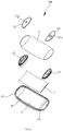
FIG. 2 is an exploded schematic view of a terminal device provided by an embodiment of the present application; -
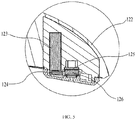
FIG. 3 is a cross-sectional view of the terminal device ofFIG. 1 , taken along the line of III-III; -
FIG. 4 is an exploded schematic view of an earphone assembly provided by an embodiment of the present application; -
FIG. 5 is an enlarged view of a circled portion V ofFIG. 3 ; -
FIG. 6 is an exploded schematic view of a microphone assembly provided by an embodiment of the present application; -
FIG. 7 is a partially inverted, enlarged view of a circled portion VII ofFIG. 3 ; -
FIG. 8 is an exploded schematic view of a pedestal provided by an embodiment of the present application; -
FIG. 9 is a schematic view of another perspective ofFIG. 8 . - The technical solutions in the embodiments of the present application will be described clearly and completely hereinafter with reference to the accompanying drawings in the embodiments of the present application. Apparently, the described embodiments are merely a part but not all embodiments of the present application. All other embodiments obtained by those skilled in the art based on the embodiments of the present application without paying any creative labor shall fall in the protecting scope of the present application.
- For ease of description, spatial relative terms, for example, "under", "below", "down", "above", "on", or the like, may be described a relationship between one element or feature and another element or feature as shown in the figures. It should be noted that when one element or layer is referred as being "on" another element or layer, or being "connected with" or "coupled to" another element or layer, it may be directly on the other element or layer, directly be connected or coupled to another element or layer, or may be present an intervening element or layer.
- It should be understood that the terms used herein is for the purpose of describing particular embodiments only, and is not intended to limit the application. As used herein, the singular forms "a" and "the" are intended to include the plural forms as well, unless the context clearly indicates otherwise. Furthermore, the terms "include" and/or "comprise" when used in this specification indicate the presence of stated features, integers, steps, elements, and/or components, but do not preclude the presence or addition of one or more other features, integers, presence, or addition of steps, elements, components, and/or groups thereof. Described later in the specification is a preferred embodiment for carrying out the present application. However, the description is for the purpose illustrating the general principles of the present application, and the description is not intended to limit the scope of the present application. The scope of the present application should be defined by the appended claims.
- As shown in
FIG. 1 , anelectronic device 1000 is provided by the embodiment of the present application, the electronic device 1000includes aterminal device 100 and apedestal 200, and theterminal device 100 is located on thepedestal 200. - In the embodiment of the present invention, the
electronic device 1000 may be, but is not limited to, a telephone, a mobile phone, or other electronic devices. In the embodiment, theelectronic device 1000 is configured as the telephone for illustration. - As shown in
FIGS. 2 to 7 , which are structural schematic views of theelectronic device 100 provided by one embodiment of the present application. Theterminal device 100 includes amain body 1 and aflexible touch panel 2. Themain body 1 includes asubstrate 11, anearphone assembly 12, and amicrophone assembly 13. Theearphone assembly 12 and themicrophone assembly 13 are respectively set on thesubstrate 11, and theearphone assembly 12 is set opposite to themicrophone assembly 13. Theflexible touch panel 2 is set on a surface of thesubstrate 11, and located between theearphone assembly 12 and themicrophone assembly 13. - Specifically, an
earphone cavity 111 and amicrophone cavity 112 opposite to theearphone cavity 111 are defined in thesubstrate 11. Theearphone assembly 12 and themicrophone assembly 13 are set in theearphone cavity 111 and themicrophone cavity 112, respectively. Theearphone assembly 12 includes anearphone cover 121 covering theearphone cavity 111 and enclosing an opening of theearphone cavity 111. Themicrophone assembly 13 includes a microphone cover131setonthe microphone cavity 112 and enclosing an opening of the microphone cavity 112.The opening of theearphone cavity 111 and the opening of themicrophone cavity 112 are enclosed by theearphone cover 121 and themicrophone cover 131, thus to prevent dust or debris from entering theearphone cavity 111 and themicrophone cavity 112, and facilitate to clean. - In the embodiment, the
substrate 11 is integrally made from a monolithic piece of transparent material. Specifically, the material of thesubstrate 11 may be selected as acrylic and integrally molded, to ensure the transparency of thesubstrate 11 and facilitate the processing of thesubstrate 11. In addition, thesubstrate 11 adopts the acrylic material, so that theterminal device 100 may be light and portable. In order to further improve an appearance and decorative effect of theterminal device 100, thesubstrate 11 may be substantially an arc-shaped block structure, and edges of thesubstrate 11 may be transitioned in a rounded corner. The design of the arc-shaped block structure enables thesubstrate 11 to be more in line with an ergonomic design, which is easy for user to hold. Meanwhile, the edge of the substrate is adopted as the rounded corner to further improve the comfort of the user's holding. Preferably, a cross-sectional shape of thesubstrate 11 is substantially a semi-moon shape to further ensure the good appearance and decorative effect of thesubstrate 11, and there is enough space to define theearphone cavity 111 and themicrophone cavity 112. - For further improvement, dialing numerals (not shown) are set on a surface of the
substrate 11, so that the user may see the dialing numerals through theflexible touch panel 2, and thereby realizing a communication function via dialing, and other functions. In the embodiment, the dialing numerals are set on the surface of thesubstrate 11 by a laser engraving to ensure a service life and a good decorative effect thereof. In addition, the dialing numerals are set on thesubstrate 11 by a mode of laser engraving, so that the appearance of thesubstrate 11 has an embossed effect, and further enhances the whole decorative effect of theterminal device 100. It should be understood that, in other embodiments, the dialing numerals may also be integrally formed on the surface of thesubstrate 11 when thesubstrate 11 is molded. - In the embodiment, the
earphone cavity 111 may be substantially an arc-shaped cavity defined on an end of thesubstrate 11. Themicrophone cavity 112 may be substantially an arc-shaped cavity defined on an end of thesubstrate 11 away from theearphone cavity 111, to maintain the whole appearance of thesubstrate 11. - As shown in
FIGS. 2 ,3 ,4 , and5 , theearphone assembly 12 further includes afirst housing 122, abattery 123, abracket 124, afirst circuit board 125 and aspeaker 126. Thefirst housing 122 defines abattery compartment 122a. Thebattery 123 is received in thebattery compartment 122a. In the embodiment, thefirst housing 122 is substantially an arc-shaped housing corresponding to a shape of theearphone cavity 111. Because the volume of theearphone cavity 111 is small, the volume of thefirst housing 122 is also small. Thebattery compartment 122a is set on one side of thefirst housing 122, and thebattery compartment 122a is substantially a square cavity, thus to facilitate the placement of thebattery 123. It should be understood that, in other embodiments, the appearance of thefirst housing 122 may also be adjusted according to the shape of theearphone cavity 111. For example, when theearphone cavity 111 is substantially a square cavity, thefirst housing 122 may be substantially a square housing. - For further improvement, in the embodiment, the
bracket 124 is detachably connected to thebattery compartment 122a, and thebracket 124 encloses an opening of thebattery compartment 122a to prevent dust or debris from entering thebattery compartment 122a to resolve an inconvenient cleaning problem. In addition, because thebracket 124 is detachably connected to thebattery compartment 122a, thebattery compartment 122a can be easily opened at any time for placing, replacing or checking thebattery 123. Specifically, edges of thebattery compartment 122a set a plurality of grooves (not shown). A plurality ofprotrusions 124a are set on edges of thebracket 124 corresponding to the plurality of grooves. The plurality ofprotrusions 124a are buckled in the plurality of grooves, thus to facilitate the connection between thebracket 124 and thebattery compartment 122a. Applying the buckle connection, thebracket 124 can be easily detached, and thebracket 124 can completely enclose the opening of thebattery compartment 122a. It should be understood that, in other embodiments, thebracket 124 may also be connected to thebattery compartment 122a by other manners. For example, one end of thebracket 124 may be rotatably connected to thebattery compartment 122a, and the other end may be fixed on thebattery compartment 122a by a screw, or the other end may also be provided with a protrusion, then a slot is provided at a corresponding end of thebattery compartment 122a, and the protrusion is engaged in the slot, therefore a connection between thebracket 124 and thebattery compartment 122a may be also realized. - Furthermore, the
bracket 124 includes acover plate 124b and an elastic abuttingportion 124c formed at one end of thecover plate 124b. Thecover plate 124b is clamped on the edge of the opening of thebattery compartment 122a and abuts an end surface of thebattery 123 received in thebattery compartment 122a to prevent thebattery 123 from falling off thebattery compartment 122a. The elastic abuttingportion 124c is substantially U-shaped, and bent down and then up from one end of thecover plate 124b. The elastic abuttingportion 124c elastically abuts a side surface of thebattery 123 adjacent to the end surface thereof to further fix thebattery 123 and prevent thebattery 123 from swaying in thebattery compartment 122a. Because the elastic abuttingportion 124c has elasticity, a better stabilizing effect can be obtained. - The
first circuit board 125 is set in thefirst housing 122, and thefirst circuit board 125 is electrically connected with thebattery 123. In the embodiment, in order to make the whole structure of theearphone assembly 12 be more compact, thefirst circuit board 125 is set at one side of thebattery compartment 122a to save a routing space between thefirst circuit board 125 and thebattery 123. Specifically, a supportingplatform 122b is set in thefirst housing 122. The supportingplatform 122b and thebattery compartment 122a are set side by side. Thefirst circuit board 125 is fixed on the supportingplatform 122b. Preferably, because thefirst circuit board 125 is substantially a square plate structure, thus to facilitate the fixing of thefirst circuit board 125, aslot 122c is set in thesecond housing 122, and the supportingplatform 122b is a step extending on an inner wall of theslot 122c. It should be understood that, in other embodiments, thefirst circuit board 125 may also be directly fixed on thebracket 124 to further save the routing space of thefirst circuit board 125 and thebattery 123. - The
speaker 126 is set on thefirst circuit board 125 and electrically connected with thefirst circuit board 125. In the embodiment, two pins (not shown) are set on thespeaker 126, and both of the two pins are a metal elastic piece. The two pins are electrically connected with corresponding pins of thefirst circuit board 125 to realize the electrical connection between thespeaker 126 and thefirst circuit board 125. Adopting the design that thespeaker 126 is directly set on thefirst circuit board 125, the space occupied by thefirst housing 122 can be saved, and the pins of thespeaker 126 can also be directly abutted against thefirst circuit board 125, so that thespeaker 126 is connected with thefirst circuit board 125 more tightly, to prevent thespeaker 126 from separating thefirst circuit board 125 when being used which may cause a problem of poor call effect, and thereby ensuring the reliability of theearphone assembly 12. Specifically, one surface of thefirst circuit board 125 abuts against the supportingplatform 122b, and the opposite surface is connected with thespeaker 126. Therefore, thespeaker 126 is substantially at the same height as thebracket 124. In other words, thespeaker 126 and thebracket 124 are set side by side. - The
earphone cover 121 is detachably set on theearphone cavity 111. In the embodiment, theearphone cover 121 is substantially an arc-shaped plate, which corresponds to the shape of theearphone cavity 111, and theearphone cover 121 is substantially an opaque plate to shelter the components in theearphone cavity 111. Preferably, in order to correspond to thesubstrate 11 and make the whole appearance of themain body 1 be better, theearphone cover 121 may be made of white plastic or coated with a white layer on a surface of theearphone cover 121. Theearphone cover 121 may be connected to theearphone cavity 111 by a screw, thus to ensure a tight connection between theearphone cover 121 and theearphone cavity 111, and prevent theearphone cover 121 from separating from theearphone cavity 111, causing debris, dust, or the like to enter theearphone cavity 111, and thereby causing a malfunction of thespeaker 126 and thefirst circuit board 125. - Furthermore, the
earphone cover 121 defines a plurality of soundingholes 121a, which are sequentially set, to ensure thespeaker 126 being capable of transmitting the sound for a user to hear. Specifically, each of the plurality of soundingholes 121a is set at a position of theearphone cover 121 corresponding to thespeaker 126 to ensure the sounding effect. Preferably, each of the plurality of soundingholes 121a has a filter (not shown) to prevent dust or debris from blocking the soundingholes 121a and causing a poor sounding effect. At the same time, the filter is designed in the soundinghole 121a, therefore the dust particles and the like may also be prevented from entering thespeaker 126 and thefirst circuit board 125 through the soundingholes 121a, to ensure the use reliability of elements of thefirst circuit board 125 and thespeaker 126. - Referring to
FIGS. 2 ,3 ,6 , and7 , themicrophone assembly 13 further includes asecond housing 132, asecond circuit board 133, amicrophone 134 and a plurality of LED lights 135. Thesecond circuit board 133 is fixed in thesecond housing 132. In the embodiment, thesecond housing 132 is substantially an arc housing, and the second housing 132corresponds to a shape of themicrophone cavity 112. Thesecond circuit board 133 is substantially a square plate structure, and thesecond circuit board 133 is preferably fixed in thesecond housing 132 through screws. Specifically, thesecond circuit board 133 defines a plurality of screw holes (not shown) for the screws passing through, thesecond housing 132 includes a plurality of studs (not shown), the screws pass through the screw holes and holes of the studs, therefore thecircuit board 133 may be fixed in thesecond housing 132. An inner portion of thesecond housing 132 forms a plurality of bracingbars 132a, which are vertically extended and adjacent to thesecond circuit board 133. Thefirst circuit board 125 is placed horizontally, and thesecond circuit board 133 is placed inclinedly relative to thefirst circuit board 125. In particular, thesecond circuit board 133 is inclined towards themicrophone cover 131 along a direction far away from theearphone cavity 111. - The
microphone 134 is set on thesecond circuit board 133, and themicrophone 134 is electrically connected with thesecond circuit board 133,to realize the electrical conduction of themicrophone 134. In the embodiment, themicrophone 134 may be electrically connected with thesecond circuit board 134 through a connecting wire, or may be connected with thesecond circuit board 134 by pins set on themicrophone 134. Themicrophone 134 is mounted on a surface of thesecond circuit board 133 facing towards themicrophone cover 131. - The plurality of
LED lights 135 are set side by side in thesecond housing 132, and the plurality ofLED lights 135 are electrically connected with thesecond circuit board 133. The plurality ofLED lights 135 are sandwiched between the bracingbars 132a and an inner wall of thesecond housing 132, thus to realize a positioning function. In the embodiment, the plurality ofLED lights 135 are electrically connected with thesecond circuit board 133 through a bentflexible circuit board 135a. Of course, theLED light 135 may also be set on an aluminum substrate, and then the aluminum substrate is fixed in thesecond housing 132. In addition, in order to save an inner space of thesecond housing 132, the plurality ofLED lights 135 may be directly set on thesecond circuit board 133. The plurality ofLED lights 135 are configured to emit light to irradiate thesubstrate 11 in an environment with weak light or in a dark environment, so that the user can see the dialing numerals on thesubstrate 11, and thereby make a dial-up call. Specifically, in order to facilitate the light emitted from the LED lights 135 to irradiate thesubstrate 11, thesecond housing 132 defines a plurality of light-transmittingholes 132b corresponding to the LED lights 135. The plurality ofLED lights 135 emit the light, and then the light is irradiated into thesubstrate 11 through the light-transmittingholes 132b, so that theterminal device 100 can be still used in an environment with the weak or dark light to increase the scope of its application. The plurality ofLED lights 135 may emit the same color of the light or emit different color of the light. For example, the plurality ofLED lights 135 may emit white light, red light, or yellow light simultaneously. It should be understood that the number of the LED lights 135 can be set according to actual lighting requirements, such as two, three or more. - The
microphone assembly 13 further includes a fixingframe 136, athird circuit board 137, and a vibratingelement 138. The fixingframe 136 is fixed in thesecond housing 132. In the embodiment, in order to save an inner space of thesecond housing 132, the fixingframe 136 is substantially an arc frame, which corresponds to a shape of thesecond housing 132, and the fixingframe 136 is set on one side of theLED light 135. The fixingframe 136 is fixed to thesecond housing 132 by a screw, thus to ensure the tightness of the connection between the fixingframe 136 and thesecond housing 132. - The
third circuit board 137 is fixedly set on an inclined plane of an inner portion of thesecond housing 132, and thethird circuit board 137 is electrically connected with thesecond circuit board 133 through a bentflexible circuit board 137a. Thethird circuit board 137 is more inclined than thesecond circuit board 134, that is, an inclination degree of thethird circuit board 137 relative to thefirst circuit board 125 is greater than an inclination degree of thesecond circuit board 134 relative to thefirst circuit board 125. It may also be said that an angle formed between thethird circuit board 137 and thefirst circuit board 125 is greater than an angle formed between the second circuit board 133and thefirst circuit board 125. In the embodiment, thethird circuit board 137 is electrically connected with the vibratingelement 138, thereby to realize an electrical conduction of the vibratingelement 138, and thereby alert the user. In addition, thesecond circuit board 133 and thethird circuit board 137 are designed respectively to connect different electronic components, thus to reduce the interference between the electronic components. It should be understood that, in other embodiments, thethird circuit board 137 may be omitted, if there is enough space to directly and electrically connect the vibratingelement 138 with thesecond circuit board 133, that is, theflexible circuit board 137a can be omitted simultaneously, therefore, the whole structure of themicrophone assembly 13 may be compact simultaneously, the assembly between components may be also reduced, and the production cost and the assembly cost may be reduced. - In addition, a communication module (not shown), a Bluetooth module (not shown), and a control module (not shown) are further set on the
third circuit board 137. The communication module, the Bluetooth module and the control module are electrically connected together, and the communication module, the Bluetooth module, and the control module are electrically connected with thethird circuit board 137. The call module is electrically connected with themicrophone 134 to realize a call function of themicrophone 134. The Bluetooth module is configured to realize a Bluetooth function of theterminal device 100, therefore theterminal device 100 may transfer data to, or share the data with other terminal devices through the Bluetooth module. The control module is configured to control the call module and the Bluetooth module to realize their respective functions. - The vibrating
element 138 is fixedly set on the fixingpart 136. In the embodiment, the vibratingelement 138 is fixedly set on a surface (a bottom surface of the fixingframe 136 inFig. 7 ) of the fixingframe 136 away from an opening of thesecond housing 132, thus to save the occupied space of the vibratingelement 138 in thesecond housing 132. Preferably, the vibratingelement 138 is fixedly set on the fixingframe 138 by a screw, and then connected with thethird circuit board 137 through a wire or a lead wire to realize conduction. A vibrating cavity of the vibratingelement 138 is formed in thesecond housing 132. The fixingframe 136 covers the vibrating cavity. The fixingframe 136 also includes abuckle 136a.Thebuckle 136a includes a vertical connectingpart 1361 and ahorizontal hook 1362. Thehook 1362 extends toward theearphone assembly 12 and abuts against thethird circuit board 137, thus to position thethird circuit board 137. - The
microphone cover 131 can be detachably set on themicrophone cavity 112. In the embodiment, themicrophone cover 131 is substantially an arc-shaped plate corresponding to the shape of themicrophone cavity 112, and themicrophone cover 131 is substantially an opaque plate, and the opaque plate shields the components in the microphone chamber 112.Preferably, in order to correspond to thesubstrate 11 and make the whole appearance effect of themain body 1 be better, themicrophone cover 131 may be made from white plastic or coated a white layer on a surface of themicrophone cover 131. Themicrophone cover 131 may be connected to the microphone cavity 112by a screw, thus to ensure a tightness of its connection, therefore, themicrophone cover 131 separated from themicrophone cavity 112, causing the debris or dust entering into themicrophone cavity 112 and generating an abnormal use between themicrophone 134 and thesecond circuit board 133, may be avoided. - Furthermore, the
microphone assembly 13 further includes aswitch button 139 configured to control theterminal device 100 to be turned on or off, for example, control to unlock screen, lock screen, or turn on the terminal device, turn off the terminal device, or the like. Theswitch button 139 includes aswitch portion 139a and abutton portion 139b. Theswitch portion 139a is set on thesecond circuit board 133 and electrically connected with thesecond circuit board 133. Thebutton portion 139b is set on theswitch portion 139a. Agroove 131a is set on themicrophone cover 131 corresponding to thebutton portion 139b to expose thebutton portion 139b. Thebutton portion 139b may be a silicone button, so that the user has a good hand feeling when the user presses thebutton portion 139b. In addition, thebutton portion 139b is substantially a round button, thus to facilitate a good appearance and decorative effect, and the decoration of the appearance of theterminal device 100 may be further enhanced. - For further improvement, at least one groove 14 is set on the
substrate 11. The at least one groove 14 extends along a direction of the length of thesubstrate 11 and communicates with theearphone cavity 111 and themicrophone cavity 112. The at least one groove 14 has a connecting wire (not shown) disposed therein. The connecting wire is connected with theearphone assembly 12 and themicrophone assembly 13. In the embodiment, because thesubstrate 11 is transparent and the whole shape of thesubstrate 11 is substantially an arc-shaped block, in order to prevent the connecting wire between theearphone assembly 12 and themicrophone assembly 13 from appearing on thesubstrate 11 and influence the whole appearance and decorative effect of theterminal device 100, the at least one groove 14 is set on thesubstrate 11, and the at least one groove 14 is set along edges of thesubstrate 11. Specifically, because four connecting wires are required to be connected between theearphone assembly 12 and themicrophone assembly 13, in order to prevent the connecting wires from being concentrated in one of the grooves 14, which is easily viewed on thesubstrate 11, four grooves 14 are defined, and a width of each of the grooves 14 is designed to accommodate only one of the connecting wires. Preferably, the connecting wire may be a silver wire or a copper wire with a diameter of 0.1 mm. Because the diameter of the connecting wire is small, the user can ignore the connecting wire when the user watches the terminal device, therefore, not only the appearance and decorative effect of the terminal device 100is ensured, but also an electrical connection between themicrophone assembly 13 and theearphone assembly 12 is ensured. It should be understood that, in other embodiments, the number of the groove 14 may be adjusted according to an actual connecting condition, such as two or three. It should be understood that, because theflexible touch panel 2 may conduct electricity, theflexible touch panel 2 may be configured as a conductive path of themicrophone assembly 13 and theearphone assembly 12. Therefore, in some other embodiments, it is not necessary to provide the connecting wires. - The
flexible touch panel 2 is a transparent touch panel. In the embodiment, because thesubstrate 11 is substantially an arc-shaped block structure, in order to correspond to a shape of thesubstrate 11, theflexible touch panel 2 may be bent to form an arc shape corresponding to thesubstrate 11. Theflexible touch panel 2 is attached to the surface of thesubstrate 11 with dialing numerals, so that the dialing numerals may be seen through theflexible touch panel 2, and then the flexible touch panel 2may be touched to realize the dialing. Because both of theflexible touch panel 2 and thesubstrate 11 are transparent, the wholeterminal device 100 looks like a transparent terminal device. Therefore, the appearance and decorative effect is better, and the user's experience is better. In addition, theflexible touch panel 2 is thin, so that the wholeterminal device 100 may be made thin. At the same time, because theflexible touch panel 2 is a flexible screen, theflexible touch panel 2 may directly configured as a front cover of theterminal device 100 without a protecting housing, thereby an assembly of theterminal device 100 may be further simplified. Moreover, because the mechanical structure of theflexible touch panel 2 is simple, theflexible touch panel 2 is hard to be damaged during use, to ensure the normal use of theterminal device 100. - Furthermore, in order to protect a surface of the
flexible touch panel 2 from damage or reduce fingerprints and dust on the surface of theflexible touch panel 2, theterminal device 100 further includes a protectingfilm 3 attached to theflexible touch panel 2 and covering the edge of thesubstrate 11, and exposing theearphone cover 121 and themicrophone cover 131 simultaneously. Specifically, the protectingfilm 3 may be a tempered film, a matte film or the like, and the protectingfilm 3 is set according to a different need of the user. - The
terminal device 100 is provided in the embodiment of the present invention. Thesubstrate 11 and theflexible touch panel 2 are set to allow the whole appearance of theterminal device 100 to be a transparent terminal device with the good appearance and decorative effect. At the same time, because theflexible touch panel 2 enables the user to perform the touching function, a failure problem of the button caused by pressing the button of the related art may be avoided, and thereby further ensure the reliability of the use of theterminal device 100. In addition, because thesubstrate 11 is thin, and theearphone assembly 12 is separated from themicrophone assembly 13, the wholeterminal device 100 is thin. Therefore, theterminal device 100 may have the characteristic of the excellent portability and improve user's experience. - Referring to
FIGS. 1 ,8 and9 again, which are the schematic structural views of apedestal 200 provided by an embodiment of the present invention. Thepedestal 200 is configured to support theterminal device 100, thus to charge theterminal device 100. - Specifically, the
pedestal 200 includes apedestal body 201, afourth circuit board 202 and acover plate 203. Thefourth circuit board 202 is set on thepedestal body 201. In the embodiment, in order to further enhance the appearance and decorative effect of theelectronic device 1000 and facilitate the placement of theterminal device 100, thepedestal body 201 is substantially a bowl-shaped structure, and abottom surface 201a of thepedestal body 201 is substantially planar, thus to place thepedestal body 201 conveniently on a desktop, a supporting column, or the like. In addition, in order to correspond to the appearance of theterminal device 100, thepedestal body 201 may also be made from transparent material, such as acrylic. Preferably, in order to reduce the whole quality of theelectronic device 1000, thepedestal body 201 is substantially a hollow bowl-shaped structure, and one end of thepedestal body 201 is obliquely set to increase a size of thebottom surface 201a of thepedestal body 201, thus to facilitate the placement and fixing of thepedestal body 201. It should be understood that, in other embodiments, thepedestal body 201 may further be other shapes, for example, a square block structure, a circular block structure, or the like. - The
pedestal body 201 defines a receiving cavity 201b, and thefourth circuit board 202 is received in the receiving cavity 201b. In the embodiment, acircular boss 201c is set in thepedestal body 201, thecircular boss 201c defines the receiving cavity 201b, and a supportingmember 2011 is set in the receiving cavity 201b. Thefourth circuit board 202 is clamped in the supportingmember 2011 to facilitate disassembly. It should be understood that, in other embodiments, thefourth circuit board 202 may also be fixed on the supportingmember 2011 by a screw. - The
cover plate 203 covers the receivingcavity 201a and encloses an opening of the receiving cavity 201b. In the embodiment, when thepedestal body 201 is made from transparent material, thecover plate 203 is made from non-transparent material to prevent the user from seeing the connecting wires in the receiving cavity 201b and a connection of the electronic components, and thereby improve the whole decorative effect of thepedestal 200. Thecover plate 203 is substantially a circular plate-like structure that corresponds to a shape of the receiving cavity 201b, and a central portion of thecover plate 203 is recessed to facilitate a subsequent placement of theterminal device 100. Therefore, when theterminal device 100 is placed on thecover plate 203, thesubstrate 11 with an arc structure may be completely contacted to thecover plate 203 to ensure the reliability of placement. It should be understood that, in other embodiments, thecover plate 203 may also be substantially a square plate structure, an arc plate structure, or the like. - Furthermore, a
cylindrical boss 203a corresponding to a shape of the receiving cavity 201b is set on a surface of thecover plate 203 facing towards the receiving cavity 201b, and thecylindrical boss 203a is designed to be hollow. Thecylindrical boss 203a has a screw thread configured to screw on the receiving cavity 201b, so that thecover plate 203 may cover the receiving cavity 201b. In addition, a screw connection enables thecover plate 203 to conveniently disassemble at any time, and then to check the connection of thefourth circuit board 202 to facilitate the overhaul and maintenance. It should be understood that, in other embodiments, thecover plate 203 may also be connected to the receiving cavity 201b by a buckle, or fixed to the receiving cavity 201b by a screw. - In order to enable the
pedestal 200 to charge theterminal device 100, a charging module (not shown) is set on thefourth circuit board 202. The charging module is electrically connected with thefourth circuit board 202, thus to facilitate the charge of theterminal device 100. In the embodiment, in order to charge conveniently, the charging module may be a wireless charging module, a wireless sensing module (not shown) is set in theterminal device 100 corresponding to the wireless charging module. The wireless sensing module is inductively connected with the wireless charging module, to realize the charging. Specifically, the wireless sensing module is set on thesecond circuit board 125 of theterminal device 100 and electrically connected with thesecond circuit board 125. When theterminal device 100 needs to charge, only one side of theflexible touch panel 2 is placed on thecover plate 203, thus to realize inductive charging. Of course, the wireless sensing module can also be on thefirst circuit board 125 to reduce a distance of a current transmitting to thebattery 123. - It should be understood that, in other embodiments, the charging module may also be a wired charging module, and a charging interface (not shown) is set on the
pedestal body 201. The charging interface is electrically connected with the charging module. A socket (not shown) is set on thesubstrate 11 of theterminal device 100 corresponding to the charging interface, and the socket is connected with the charging interface through a charging cable. When theterminal device 100 is charged by the charging cable, theterminal device 100 may be placed on thecover plate 203 or separated from thecover plate 203 as long as the charging cable is connected with the charging interface and the socket. - In addition, in other embodiments, a charging-connection contact may also be set on the
substrate 11, and then a charging contact may be correspondingly set on the pedestal body 201.When the charging-connection contact of thesubstrate 11 is abutted against the charging contact of thepedestal body 201, thesubstrate 11 may be charged by thepedestal 200. - The
electronic device 1000 is provided by the embodiment of the present invention. Theterminal device 100 is charged through thepedestal 200. Therefore, theterminal device 100 may not require an additional charger, thus to save component and cost. In addition, because thepedestal 200 and theterminal device 100 adopt a wireless charging manner, thus to charge theterminal device 100 conveniently, and improve the user's experience. - The
terminal device 100 and theelectronic device 1000 are provided by the present invention. Theflexible touch panel 2 is set on the substrate 11to realize the touch function during using by a user, so that a means using a mechanical button of related art may be replaced, a problem that the button is pressed in a long term causing damage can be avoided, and the reliability of theterminal device 100 may be greatly improved. At the same time, because thewhole substrate 11 is thin, and theearphone assembly 12 and themicrophone assembly 13 are set respectively on both ends of thesubstrate 11, the communication may be realized simultaneously, the whole structural compactness of theterminal device 100 may be improved, and the whole thickness of theterminal device 100 may be reduced. - In the description of the present specification, the description with reference to "one embodiment", "some embodiments", "an example", "a specific example", "some examples", similar to "first embodiment", or the like may refer to the specific feature, structure, material, or characteristic including in at least one embodiment or example of the present invention, which are described in the embodiments or examples. In the specification, the schematic representation of the above terms does not necessarily refer to the same embodiment or example. Furthermore, the specific feature, structure, material, or characteristic described in any one or more embodiments or examples may be combined in any suitable manner.
- The above embodiments do not limit the protection scope of the technical solutions. Any modification, equivalent replacement and improvement made in the spirit and principle of the above embodiments should be included in the protection scope of the technical solution.
Claims (18)
- A terminal device, comprising:a main body comprising a substrate, an earphone assembly and a microphone assembly, wherein the earphone assembly and the microphone assembly are respectively set on two opposite ends of the substrate; anda flexible touch panel set on the substrate, wherein the flexible touch panel is located between the earphone assembly and the microphone assembly.
- The terminal device of the claim 1, wherein the substrate is integrally made from a single monolithic piece of transparent material.
- The terminal device of the claim 1, wherein the substrate defines an earphone cavity and a microphone cavity opposite to the earphone cavity, the earphone assembly and the microphone assembly are respectively received in the earphone cavity and the microphone cavity.
- The terminal device of the claim 1, wherein the earphone assembly comprises a first housing, a speaker, and a first circuit board, the first circuit board is mounted in the first housing, and the speaker is electrically connected with the first circuit board.
- The terminal device of the claim 4, wherein the first housing defines a battery compartment, and the earphone assembly comprises a battery received in the battery compartment and a bracket, and the bracket fixes the battery in the battery compartment.
- The terminal device of the claim 5, wherein the bracket comprises a cover plate clamping on an opening of the battery compartment and an elastic abutting portion extending from the cover plate, the cover plate covers an end surface of the battery, and the elastic abutting portion elastically abuts against a side surface of the battery adjacent to the end surface of the battery.
- The terminal device of the claim 1, wherein the microphone assembly comprises a second housing, a second circuit board, and a microphone, the second circuit board is fixed in the second housing, and the microphone is set on the second circuit board and electrically connected with the second circuit board.
- The terminal device of the claim 7, wherein the microphone assembly further comprises a fixing frame and a vibrating element, the fixing frame is fixed in the second housing, and the vibrating element is fixed on the fixing frame.
- The terminal device of the claim 8, wherein the microphone assembly further comprises a third circuit board, the third circuit board is electrically connected with the second circuit board, and the vibrating element is electrically connected with the third circuit board.
- The terminal device of the claim 9, wherein the fixing frame comprises a hook extending toward the earphone assembly, and the hook abuts against the third circuit board.
- The terminal device of the claim 9, wherein both of the second circuit board and the third circuit board are inclined relative to the first circuit board, an angle formed between the second circuit board and the first circuit board is substantially less than an angle formed between the third circuit board and the first circuit board.
- The terminal device of the claim 7, wherein the microphone assembly further comprises an LED light, a position of the second housing corresponding to the LED light defines a light-transmitting hole, a light emitted by the LED light is irradiated into the substrate through the light-transmitting hole.
- The terminal device of the claim 12, wherein a bracing bar is formed in the second housing, and the LED light is sandwiched between the bracing bar and an inner wall of the second housing.
- The terminal device of the claim 7, wherein the microphone assembly further comprises a switch button, the switch button comprises a button portion and a switch portion, the switch portion is set on the second circuit board and electrically connected with the second circuit board, and the button portion is set on the switch portion.
- The terminal device of the claim 1, wherein the substrate defines a groove, the groove extends along a length direction of the substrate, a connecting wire is set in the groove, and the connecting wire is connected with the earphone assembly and the microphone assembly.
- The terminal device of the claim 1, wherein the flexible touch panel is configured as a conductive path to electrically connect the microphone assembly with the earphone assembly.
- An electronic device, wherein the electronic device comprises a pedestal and the terminal device of any one of claims 1 to 16, and the terminal device is located on the pedestal.
- The electronic device of claim 17, wherein the pedestal comprises a pedestal body, a fourth circuit board and a cover plate, the pedestal body defines a receiving cavity, and the fourth circuit board is received in the receiving cavity, the cover plate covers the receiving cavity and encloses an opening of the receiving cavity.
Applications Claiming Priority (1)
| Application Number | Priority Date | Filing Date | Title |
|---|---|---|---|
| PCT/CN2015/100156 WO2017113311A1 (en) | 2015-12-31 | 2015-12-31 | Terminal and electronic device |
Publications (2)
| Publication Number | Publication Date |
|---|---|
| EP3399730A1 true EP3399730A1 (en) | 2018-11-07 |
| EP3399730A4 EP3399730A4 (en) | 2019-08-14 |
Family
ID=59224256
Family Applications (1)
| Application Number | Title | Priority Date | Filing Date |
|---|---|---|---|
| EP15911937.9A Withdrawn EP3399730A4 (en) | 2015-12-31 | 2015-12-31 | TERMINAL AND ELECTRONIC DEVICE |
Country Status (5)
| Country | Link |
|---|---|
| US (1) | US10536567B2 (en) |
| EP (1) | EP3399730A4 (en) |
| JP (1) | JP6586527B2 (en) |
| CN (1) | CN107211054A (en) |
| WO (1) | WO2017113311A1 (en) |
Families Citing this family (8)
| Publication number | Priority date | Publication date | Assignee | Title |
|---|---|---|---|---|
| CN206284396U (en) * | 2016-11-11 | 2017-06-30 | 深圳市艾维普思科技股份有限公司 | Battery case and electronic cigarette |
| CN108399917B (en) * | 2018-01-26 | 2023-08-04 | 百度在线网络技术(北京)有限公司 | Speech processing method, apparatus and computer readable storage medium |
| CN108443666A (en) * | 2018-04-26 | 2018-08-24 | 置富科技(深圳)股份有限公司 | A kind of support rack for mobile terminal |
| CN108882077B (en) | 2018-08-24 | 2024-08-23 | 深圳市韶音科技有限公司 | Electronic component and glasses |
| CN112882582B (en) | 2019-11-29 | 2023-09-01 | 华为技术有限公司 | Touchpad components and electronics |
| CN111669932B (en) * | 2020-07-10 | 2022-01-25 | Oppo广东移动通信有限公司 | Circuit board assembly and electronic equipment |
| CN112887867B (en) * | 2021-01-28 | 2022-06-24 | 上海闻泰信息技术有限公司 | Earphone assembly |
| US12035091B2 (en) | 2021-06-10 | 2024-07-09 | Samsung Electronics Co., Ltd. | Electronic device including microphone module |
Family Cites Families (26)
| Publication number | Priority date | Publication date | Assignee | Title |
|---|---|---|---|---|
| JPH0221760A (en) * | 1988-07-11 | 1990-01-24 | Matsushita Electric Ind Co Ltd | Handset |
| JP2889320B2 (en) * | 1990-05-17 | 1999-05-10 | 沖電気工業株式会社 | Telephone |
| JP2979875B2 (en) * | 1993-01-27 | 1999-11-15 | 日本電気株式会社 | mobile phone |
| JP2001007905A (en) * | 1999-06-18 | 2001-01-12 | Hitachi Kokusai Electric Inc | Paging receiver display structure |
| EP1724800B1 (en) * | 2005-05-19 | 2008-12-17 | Samsung Electronics Co., Ltd. | Key pad and keypad assembly |
| CN2919719Y (en) | 2006-05-08 | 2007-07-04 | 程洪 | Waterproof telephone with touch screen |
| US8650925B2 (en) * | 2007-01-05 | 2014-02-18 | Apple Inc. | Extrusion method for fabricating a compact tube with internal features |
| JP2008306244A (en) * | 2007-06-05 | 2008-12-18 | Mitsubishi Electric Corp | Mobile terminal device |
| CN101600005A (en) * | 2008-06-04 | 2009-12-09 | 深圳富泰宏精密工业有限公司 | Microphone assembly and use its portable electron device |
| CN101360136A (en) * | 2008-06-27 | 2009-02-04 | 杨开艳 | a mobile phone |
| CN201233573Y (en) * | 2008-06-30 | 2009-05-06 | 宇龙计算机通信科技(深圳)有限公司 | Electronic terminal having touch control keyboard |
| CN201303366Y (en) | 2008-09-13 | 2009-09-02 | 惠州市惠阳区美思奇实业发展有限公司 | Quasi-cordless telephone with handset with functions of switching on-off telephone |
| CN101715032A (en) | 2009-05-07 | 2010-05-26 | 翁印嵩 | Telephone fax machine with touch display screen |
| TW201110170A (en) * | 2009-09-02 | 2011-03-16 | Ichia Tech Inc | Manufacturing method for keycap structure, keypad structure, panel, and housing |
| CN201515405U (en) | 2009-10-26 | 2010-06-23 | 深圳国威电子有限公司 | Touch-sensitive keyboard cordless handset |
| TW201119329A (en) * | 2009-11-20 | 2011-06-01 | Utw Technologies Corp | Docking station for a wireless communication device |
| WO2011099581A1 (en) * | 2010-02-12 | 2011-08-18 | 京セラ株式会社 | Portable electronic device |
| US9158371B2 (en) * | 2010-03-25 | 2015-10-13 | Nokia Technologies Oy | Contortion of an electronic apparatus |
| JP5717170B2 (en) * | 2010-09-16 | 2015-05-13 | 埼玉日本電気株式会社 | Electronic equipment and case |
| JP5876747B2 (en) * | 2012-02-23 | 2016-03-02 | シャープ株式会社 | COMMUNICATION TERMINAL DEVICE, CONTROL METHOD, PROGRAM, AND RECORDING MEDIUM |
| JP2013239900A (en) * | 2012-05-15 | 2013-11-28 | Sharp Corp | Portable terminal |
| CN203014890U (en) | 2012-12-06 | 2013-06-19 | 周城城 | Handset having function of sound amplification |
| US9182864B2 (en) * | 2013-06-03 | 2015-11-10 | Rajkumari Mohindra | Pressure sensitive projected capacitive touch sensing |
| CN103338033A (en) * | 2013-06-05 | 2013-10-02 | 海芯科技(厦门)有限公司 | Capacitance-type touch keys applied to cell phones and a design method thereof |
| KR20150067673A (en) | 2013-12-10 | 2015-06-18 | 엘지전자 주식회사 | Wireless charging device |
| US10222840B2 (en) * | 2014-10-15 | 2019-03-05 | Samsung Electronics Co., Ltd. | Display apparatus and controlling method thereof |
-
2015
- 2015-12-31 EP EP15911937.9A patent/EP3399730A4/en not_active Withdrawn
- 2015-12-31 CN CN201580073624.9A patent/CN107211054A/en active Pending
- 2015-12-31 WO PCT/CN2015/100156 patent/WO2017113311A1/en not_active Ceased
- 2015-12-31 US US15/744,975 patent/US10536567B2/en not_active Expired - Fee Related
- 2015-12-31 JP JP2018528250A patent/JP6586527B2/en not_active Expired - Fee Related
Also Published As
| Publication number | Publication date |
|---|---|
| JP6586527B2 (en) | 2019-10-02 |
| US10536567B2 (en) | 2020-01-14 |
| WO2017113311A1 (en) | 2017-07-06 |
| JP2018537040A (en) | 2018-12-13 |
| US20180213072A1 (en) | 2018-07-26 |
| EP3399730A4 (en) | 2019-08-14 |
| CN107211054A (en) | 2017-09-26 |
Similar Documents
| Publication | Publication Date | Title |
|---|---|---|
| US10536567B2 (en) | Terminal device and electronic device | |
| KR101886752B1 (en) | Mobile terminal | |
| KR101587138B1 (en) | Mobile terminal | |
| US8260382B2 (en) | Portable sliding wireless communication terminal | |
| US9746882B2 (en) | Electronic device with curved display module | |
| KR102167928B1 (en) | Mobile terminal | |
| EP3448056B1 (en) | Electronic device including electronic part and earphone jack assembly | |
| CN107770315A (en) | Mobile terminal | |
| KR100995424B1 (en) | Wireless communication terminal with removable active housing and associated connector | |
| KR101734286B1 (en) | Connecting terminal and mobile terminal having the same | |
| CN209748935U (en) | Terminal device | |
| KR100757448B1 (en) | Handheld terminal | |
| KR20150076961A (en) | Protective cover and electronic device having it | |
| JP6543740B1 (en) | Electronic device and receptacle connector | |
| CN107979665A (en) | Mobile terminal | |
| CN116249954A (en) | Electronic equipment | |
| CN108206874B (en) | Mobile phone shell | |
| CN108318897B (en) | Tracking device | |
| RU2009111904A (en) | STATIONARY DEVICE FOR HOME NEGOTIATION DEVICE | |
| CN111182425A (en) | Electronic device | |
| CN214756839U (en) | Charging box capable of automatically switching on and off charging of Bluetooth headset | |
| JP5100679B2 (en) | Earpiece structure and cellular phone in telephone device | |
| CN110602286A (en) | Electronic equipment, sensor extension device and electronic equipment assembly | |
| KR101772078B1 (en) | Mobile terminal | |
| KR102097081B1 (en) | Assembling structure for module and electronic device having it |
Legal Events
| Date | Code | Title | Description |
|---|---|---|---|
| STAA | Information on the status of an ep patent application or granted ep patent |
Free format text: STATUS: THE INTERNATIONAL PUBLICATION HAS BEEN MADE |
|
| PUAI | Public reference made under article 153(3) epc to a published international application that has entered the european phase |
Free format text: ORIGINAL CODE: 0009012 |
|
| STAA | Information on the status of an ep patent application or granted ep patent |
Free format text: STATUS: REQUEST FOR EXAMINATION WAS MADE |
|
| 17P | Request for examination filed |
Effective date: 20180430 |
|
| AK | Designated contracting states |
Kind code of ref document: A1 Designated state(s): AL AT BE BG CH CY CZ DE DK EE ES FI FR GB GR HR HU IE IS IT LI LT LU LV MC MK MT NL NO PL PT RO RS SE SI SK SM TR |
|
| AX | Request for extension of the european patent |
Extension state: BA ME |
|
| DAV | Request for validation of the european patent (deleted) | ||
| DAX | Request for extension of the european patent (deleted) | ||
| A4 | Supplementary search report drawn up and despatched |
Effective date: 20190715 |
|
| RIC1 | Information provided on ipc code assigned before grant |
Ipc: G06F 3/01 20060101ALI20190709BHEP Ipc: H04M 1/23 20060101AFI20190709BHEP Ipc: G06F 1/16 20060101ALI20190709BHEP Ipc: H04M 1/02 20060101ALI20190709BHEP Ipc: G06F 3/041 20060101ALI20190709BHEP Ipc: H04M 1/03 20060101ALI20190709BHEP |
|
| STAA | Information on the status of an ep patent application or granted ep patent |
Free format text: STATUS: THE APPLICATION HAS BEEN WITHDRAWN |
|
| 18W | Application withdrawn |
Effective date: 20200203 |