EP3399581A1 - Reinigungsvorrichtung, mit einer reinigungsrolle, für schutzfilm zur batteriezellenherstellung - Google Patents
Reinigungsvorrichtung, mit einer reinigungsrolle, für schutzfilm zur batteriezellenherstellung Download PDFInfo
- Publication number
- EP3399581A1 EP3399581A1 EP17875608.6A EP17875608A EP3399581A1 EP 3399581 A1 EP3399581 A1 EP 3399581A1 EP 17875608 A EP17875608 A EP 17875608A EP 3399581 A1 EP3399581 A1 EP 3399581A1
- Authority
- EP
- European Patent Office
- Prior art keywords
- protective film
- roll
- cleaning
- foreign substances
- cleaning roll
- Prior art date
- Legal status (The legal status is an assumption and is not a legal conclusion. Google has not performed a legal analysis and makes no representation as to the accuracy of the status listed.)
- Granted
Links
- 230000001681 protective effect Effects 0.000 title claims abstract description 165
- 238000004140 cleaning Methods 0.000 title claims abstract description 119
- 238000004519 manufacturing process Methods 0.000 title description 3
- 239000010408 film Substances 0.000 claims abstract description 165
- 239000000126 substance Substances 0.000 claims abstract description 66
- 238000004804 winding Methods 0.000 claims abstract description 55
- 238000000034 method Methods 0.000 claims abstract description 27
- 239000010409 thin film Substances 0.000 claims abstract description 19
- 238000003475 lamination Methods 0.000 claims abstract description 12
- 238000003825 pressing Methods 0.000 claims abstract description 10
- 238000010438 heat treatment Methods 0.000 claims abstract description 8
- 239000002245 particle Substances 0.000 claims description 22
- WHXSMMKQMYFTQS-UHFFFAOYSA-N Lithium Chemical compound [Li] WHXSMMKQMYFTQS-UHFFFAOYSA-N 0.000 description 4
- 229910052744 lithium Inorganic materials 0.000 description 4
- 230000007547 defect Effects 0.000 description 2
- 239000000463 material Substances 0.000 description 2
- 239000000243 solution Substances 0.000 description 2
- 238000003915 air pollution Methods 0.000 description 1
- 230000003247 decreasing effect Effects 0.000 description 1
- 230000006866 deterioration Effects 0.000 description 1
- 230000000694 effects Effects 0.000 description 1
- 239000008151 electrolyte solution Substances 0.000 description 1
- 238000002474 experimental method Methods 0.000 description 1
- 239000002803 fossil fuel Substances 0.000 description 1
- 239000007921 spray Substances 0.000 description 1
- 238000002834 transmittance Methods 0.000 description 1
Images

Classifications
-
- B—PERFORMING OPERATIONS; TRANSPORTING
- B65—CONVEYING; PACKING; STORING; HANDLING THIN OR FILAMENTARY MATERIAL
- B65H—HANDLING THIN OR FILAMENTARY MATERIAL, e.g. SHEETS, WEBS, CABLES
- B65H20/00—Advancing webs
- B65H20/02—Advancing webs by friction roller
-
- B—PERFORMING OPERATIONS; TRANSPORTING
- B08—CLEANING
- B08B—CLEANING IN GENERAL; PREVENTION OF FOULING IN GENERAL
- B08B1/00—Cleaning by methods involving the use of tools
- B08B1/30—Cleaning by methods involving the use of tools by movement of cleaning members over a surface
- B08B1/32—Cleaning by methods involving the use of tools by movement of cleaning members over a surface using rotary cleaning members
-
- B—PERFORMING OPERATIONS; TRANSPORTING
- B08—CLEANING
- B08B—CLEANING IN GENERAL; PREVENTION OF FOULING IN GENERAL
- B08B1/00—Cleaning by methods involving the use of tools
- B08B1/20—Cleaning of moving articles, e.g. of moving webs or of objects on a conveyor
-
- B—PERFORMING OPERATIONS; TRANSPORTING
- B08—CLEANING
- B08B—CLEANING IN GENERAL; PREVENTION OF FOULING IN GENERAL
- B08B5/00—Cleaning by methods involving the use of air flow or gas flow
- B08B5/02—Cleaning by the force of jets, e.g. blowing-out cavities
- B08B5/023—Cleaning travelling work
- B08B5/026—Cleaning moving webs
-
- B—PERFORMING OPERATIONS; TRANSPORTING
- B08—CLEANING
- B08B—CLEANING IN GENERAL; PREVENTION OF FOULING IN GENERAL
- B08B7/00—Cleaning by methods not provided for in a single other subclass or a single group in this subclass
- B08B7/0028—Cleaning by methods not provided for in a single other subclass or a single group in this subclass by adhesive surfaces
-
- B—PERFORMING OPERATIONS; TRANSPORTING
- B65—CONVEYING; PACKING; STORING; HANDLING THIN OR FILAMENTARY MATERIAL
- B65H—HANDLING THIN OR FILAMENTARY MATERIAL, e.g. SHEETS, WEBS, CABLES
- B65H18/00—Winding webs
-
- B—PERFORMING OPERATIONS; TRANSPORTING
- B65—CONVEYING; PACKING; STORING; HANDLING THIN OR FILAMENTARY MATERIAL
- B65H—HANDLING THIN OR FILAMENTARY MATERIAL, e.g. SHEETS, WEBS, CABLES
- B65H37/00—Article or web delivery apparatus incorporating devices for performing specified auxiliary operations
-
- H—ELECTRICITY
- H01—ELECTRIC ELEMENTS
- H01M—PROCESSES OR MEANS, e.g. BATTERIES, FOR THE DIRECT CONVERSION OF CHEMICAL ENERGY INTO ELECTRICAL ENERGY
- H01M10/00—Secondary cells; Manufacture thereof
- H01M10/04—Construction or manufacture in general
- H01M10/0404—Machines for assembling batteries
-
- H—ELECTRICITY
- H01—ELECTRIC ELEMENTS
- H01M—PROCESSES OR MEANS, e.g. BATTERIES, FOR THE DIRECT CONVERSION OF CHEMICAL ENERGY INTO ELECTRICAL ENERGY
- H01M10/00—Secondary cells; Manufacture thereof
- H01M10/04—Construction or manufacture in general
- H01M10/0468—Compression means for stacks of electrodes and separators
-
- H—ELECTRICITY
- H01—ELECTRIC ELEMENTS
- H01M—PROCESSES OR MEANS, e.g. BATTERIES, FOR THE DIRECT CONVERSION OF CHEMICAL ENERGY INTO ELECTRICAL ENERGY
- H01M10/00—Secondary cells; Manufacture thereof
- H01M10/05—Accumulators with non-aqueous electrolyte
- H01M10/052—Li-accumulators
-
- H—ELECTRICITY
- H01—ELECTRIC ELEMENTS
- H01M—PROCESSES OR MEANS, e.g. BATTERIES, FOR THE DIRECT CONVERSION OF CHEMICAL ENERGY INTO ELECTRICAL ENERGY
- H01M10/00—Secondary cells; Manufacture thereof
- H01M10/05—Accumulators with non-aqueous electrolyte
- H01M10/058—Construction or manufacture
-
- H—ELECTRICITY
- H01—ELECTRIC ELEMENTS
- H01M—PROCESSES OR MEANS, e.g. BATTERIES, FOR THE DIRECT CONVERSION OF CHEMICAL ENERGY INTO ELECTRICAL ENERGY
- H01M10/00—Secondary cells; Manufacture thereof
- H01M10/05—Accumulators with non-aqueous electrolyte
- H01M10/058—Construction or manufacture
- H01M10/0585—Construction or manufacture of accumulators having only flat construction elements, i.e. flat positive electrodes, flat negative electrodes and flat separators
-
- B—PERFORMING OPERATIONS; TRANSPORTING
- B65—CONVEYING; PACKING; STORING; HANDLING THIN OR FILAMENTARY MATERIAL
- B65H—HANDLING THIN OR FILAMENTARY MATERIAL, e.g. SHEETS, WEBS, CABLES
- B65H2301/00—Handling processes for sheets or webs
- B65H2301/50—Auxiliary process performed during handling process
- B65H2301/51—Modifying a characteristic of handled material
- B65H2301/511—Processing surface of handled material upon transport or guiding thereof, e.g. cleaning
- B65H2301/5115—Cleaning
-
- B—PERFORMING OPERATIONS; TRANSPORTING
- B65—CONVEYING; PACKING; STORING; HANDLING THIN OR FILAMENTARY MATERIAL
- B65H—HANDLING THIN OR FILAMENTARY MATERIAL, e.g. SHEETS, WEBS, CABLES
- B65H2801/00—Application field
- B65H2801/72—Fuel cell manufacture
-
- Y—GENERAL TAGGING OF NEW TECHNOLOGICAL DEVELOPMENTS; GENERAL TAGGING OF CROSS-SECTIONAL TECHNOLOGIES SPANNING OVER SEVERAL SECTIONS OF THE IPC; TECHNICAL SUBJECTS COVERED BY FORMER USPC CROSS-REFERENCE ART COLLECTIONS [XRACs] AND DIGESTS
- Y02—TECHNOLOGIES OR APPLICATIONS FOR MITIGATION OR ADAPTATION AGAINST CLIMATE CHANGE
- Y02E—REDUCTION OF GREENHOUSE GAS [GHG] EMISSIONS, RELATED TO ENERGY GENERATION, TRANSMISSION OR DISTRIBUTION
- Y02E60/00—Enabling technologies; Technologies with a potential or indirect contribution to GHG emissions mitigation
- Y02E60/10—Energy storage using batteries
-
- Y—GENERAL TAGGING OF NEW TECHNOLOGICAL DEVELOPMENTS; GENERAL TAGGING OF CROSS-SECTIONAL TECHNOLOGIES SPANNING OVER SEVERAL SECTIONS OF THE IPC; TECHNICAL SUBJECTS COVERED BY FORMER USPC CROSS-REFERENCE ART COLLECTIONS [XRACs] AND DIGESTS
- Y02—TECHNOLOGIES OR APPLICATIONS FOR MITIGATION OR ADAPTATION AGAINST CLIMATE CHANGE
- Y02P—CLIMATE CHANGE MITIGATION TECHNOLOGIES IN THE PRODUCTION OR PROCESSING OF GOODS
- Y02P70/00—Climate change mitigation technologies in the production process for final industrial or consumer products
- Y02P70/50—Manufacturing or production processes characterised by the final manufactured product
Definitions
- the present disclosure relates to a device including a cleaning roll, and for cleaning a protective film for preparing a battery cell.
- Rechargeable secondary batteries are attracting attention as a power source for devices which require high output and large capacity such as electric vehicles (EVs), hybrid EVs (HEVs), plug-in HEVs, and the like, which have been proposed as a solution to the problem of air pollution generated by conventional gasoline vehicles and diesel vehicles using fossil fuel.
- EVs electric vehicles
- HEVs hybrid EVs
- plug-in HEVs plug-in HEVs
- lithium secondary batteries As described above, as the devices in which a secondary battery is applied are being diversified, lithium secondary batteries have been diversified to provide the output and capacity suitable for the devices, and there is additionally a strong demand for the miniaturization of lithium secondary batteries.
- a lithium secondary battery includes a battery case, and an electrode assembly and an electrolytic solution incorporated in the battery case.
- Lithium secondary batteries are classified into cylindrical batteries, prismatic batteries, and pouch-type batteries according to an outer shape of the battery case.
- the electrode assembly includes a positive electrode, a negative electrode, and a separator interposed between the positive electrode and the negative electrode, and a plurality of positive electrodes and negative electrodes are alternately stacked.
- the electrode assembly in which a plurality of positive electrodes, negative electrodes, and separators are stacked is subjected to a lamination process of bonding the positive electrodes, the negative electrodes, and the separators by heating and pressing.
- heating and pressing the electrode assembly While heating and pressing the electrode assembly, in order to prevent the outer surface of the electrode assembly from being damaged by a pressing plate, heating and pressing are performed in a state in which a protective film is attached to a portion where the electrode assembly faces the pressing plate.
- the protective film is only intended to protect the outer surface of the electrode assembly during the heating and pressing processes, a production cost can be reduced by reusing the film after the lamination process.
- a protective film which has already been used for the lamination process may inevitably be contaminated with microscopic foreign substances during the heating and pressing processes.
- the electrode assembly When the protective film contaminated by the foreign substances is attached to the outer surface of the electrode assembly again and the lamination process is performed, the electrode assembly may become contaminated with foreign substances.
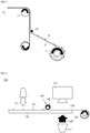
- FIG. 1 is a schematic view briefly showing a winding device for a protective film used in a conventional lamination process.
- a protective film winding device 10 includes a feed roll 11, a guide roll 15 and a winding roll 17.
- a protective film 12 is moved in one direction, and the protective film 12 is wound around the winding roll 17 by the rotation of the winding roll 17 corresponding to the rotation of the feed roll 11.
- the present disclosure is provided to solve the above-described problems of the related art and technical problems which have been identified in the past.
- the inventors of the present application have conducted intense research and various experiments and have confirmed that when a cleaning device for a protective film is formed with a specific structure, foreign substances remaining on the protective film can be adsorbed and removed, and ultimately it is possible to prevent deterioration of battery capacity and a battery cell defect beforehand, thereby attaining the present disclosure.
- the present disclosure provides a device for cleaning a protective film to be attached to an outer surface of a laminate during a lamination process of heating and pressing the laminate of electrodes and a separator to produce an electrode assembly for a battery cell, including: a feed roll configured to supply the protective film; at least one guide roll configured to guide a progress of the protective film supplied from the feed roll; a cleaning roll located between the feed roll and a winding roll and configured to remove foreign substances remaining on the protective film supplied from the feed roll; and the winding roll configured to wind the protective film from which foreign substances have been removed by the cleaning roll, wherein a nano thin film is formed on an outer surface of the cleaning roll to adsorb and remove the foreign substances remaining on the protective film.
- the feed roll, the guide roll, the winding roll, and the cleaning roll may be positioned such that their rotation axes are parallel to each other.
- the feed roll, the guide roll, the winding roll, and the cleaning roll may rotate in the same direction and with the same circumferential velocity.
- the protective film supplied from the feed roll may be moved to the winding roll through the cleaning roll.
- the feed roll configured to supply the protective film and the winding roll configured to wind the protective film may not be separately rotated by separate power sources, but may be formed so that the power source is connected only to a rotation axis of the winding roll.
- the protective film may be transported while the feed roll configured to supply the protective film is rotated.
- the protective film supplied from the feed roll may be transported in a taut state having a predetermined tensile force, thereby increasing a foreign substance cleaning efficiency of the cleaning roll.
- a sensor positioned between the cleaning roll and the winding roll with respect to a movement direction of the protective film and configured to check whether or not the foreign substances on the protective film have been removed may be further included.
- the senor may include a light source part configured to irradiate, onto the protective film, light transmitted through the protective film; and a monitor part configured to sense the light transmitted through the protective film.
- the light source part and the monitor part may be positioned in a straight line with the protective film interposed therebetween and the sensor may be configured to visually check through the monitor part whether or not the foreign substances on the protective film have been removed.
- the protective film may be formed of a light-transmitting material.
- an intensity of the light emitted from the light source part may be adjusted depending on the material of the protective film.
- the monitor part may be configured to sense the light transmitted through the protective film, so that an operator may visually check through the monitor part whether or not the foreign substances on the protective film have been removed.
- the light irradiated from the light source part cannot pass through the foreign substances. Therefore, when the foreign substances have not been removed by the cleaning roll, the foreign substances may be seen as a shadow or a dot in the monitor part.
- the brightness of the protective film viewed from the monitor part may be significantly reduced.
- an operator may stop the movement of the protective film.
- the senor may further include a light intensity sensing part configured to measure a light intensity of the light transmitted through the protective film; and operations of the winding roll and the feel roll may be stopped when the light intensity measured by the light intensity sensing part is less than a predetermined value.
- the senor may include the light intensity sensing part which, by using the property of the light emitted from the light source part of not passing through the foreign substances, automatically measures the light intensity of the light transmitted through the protective film.
- a reference value of the light intensity for adjustment of the operations of the winding roll and the feed roll by the light intensity sensing part may be adjusted according to the operator's choice.
- the operations of the winding roll and the feed roll stop which means that there is a foreign substance not yet removed on the protective film, and therefore the foreign substance needs to be removed.
- the cleaning roll may be formed to be movable in a movement direction of the protective film and an opposite direction thereof, and when it is confirmed by the sensor that foreign substances have not been removed, the cleaning roll may move in the movement direction of the protective film and the opposite direction thereof, and the foreign substances on the protective film may be removed.
- Only the cleaning roll may rotate and move in the movement direction of the protective film to remove the foreign substances which are not removed by the cleaning roll in a state in which the operations of the winding roll and the feed roll are stopped, that is, in a state in which the movement of the protective film is stopped.
- the cleaning roll rotates and moves, the remaining foreign substances on the protective film may be removed, and the cleaning roll may be moved back into place by being moved back and forth.
- a nano thin film formed on an outer surface of the cleaning roll may be formed such that particles having a particle size of 0.5 ⁇ m or less are adsorbed.
- an air compressor may be further included to spray air on both sides of the protective film and remove large particles of the foreign substances.
- the movement direction of the protective film may be changed to be vertical by the guide roll, and by changing the movement direction of the protective film, the large particles of the foreign substances may be naturally removed when the movement direction of the protective film is changed,.
- the guide roll may be a plurality of guide rolls, and sections in which the movement direction of the protective film is an upward vertical direction or a downward vertical direction may be formed.
- power sources may be respectively connected to the feed roll configured to supply the protective film and the winding roll configured to wind the protective film.
- the power source connected to the feed roll may be formed to rotate the feed roll in a direction opposite to a rotating direction of the winding roll, and when the feed roll is reversed, the protective film may be transported to the feed roll again.
- the protective film may be moved to the winding roll as the winding roll rotates, and then the protective film wound on the winding roll may be unwound and moved to the feed roll as the feed roll rotates in a reverse direction.
- the protective film may be moved in both directions so that a portion where the foreign substances on the protective film have not been removed may be repeatedly passed through the cleaning roll.
- the cleaning roll may include a first cleaning roll and a second cleaning roll; nano thin films of the first cleaning roll and the second cleaning roll may be formed to adsorb foreign particles having different sizes, and the first cleaning roll may be formed to adsorb larger foreign particles than the second cleaning roll; and the first cleaning roll and the second cleaning roll may be arranged in sequence on the basis of a movement direction of the protective film moving from the feed roll to the winding roll.
- the nano thin film formed on the first cleaning roll may be formed so that particles having a size of 1 ⁇ m to 2 ⁇ m are adsorbed
- the nano thin film formed on the second cleaning roll may be formed so that particles having a size of less than 0.5 ⁇ m are adsorbed.
- the cleaning roll may include a pair of rolls, and the rolls may be formed in a straight line in a vertical direction with the protective film interposed therebetween.
- the foreign substances remaining on both sides of the protective film may be removed while the protective film passes between the pair of rolls.
- a device for cleaning a protective film and according to the present disclosure includes a cleaning roll having a nano thin film on its outer surface, thereby effectively removing foreign substances on the protective film contaminated in a lamination process. Accordingly, the protective film can be reused and a production cost can be reduced.
- FIG. 2 is a schematic view briefly showing a process of cleaning a protective film using a protective film cleaning device according to an exemplary embodiment of the present disclosure.
- a cleaning device for a protective film 100 may include an air compressor 120, a feed roll (not shown), a cleaning roll 140, a winding roll 160, a support frame 130, and sensors 151 and 153.
- the air compressor 120 may strongly jet air to the protective film 110 according to the rotation of the winding roll 160 when the protective film 110 moves so that foreign substances 112 remaining on the protective film 110 may be primarily removed.
- the protective film 110 may be formed to move on the support frame 130, and the cleaning roll 140 may be rotatably fixed to an upper part of the support frame 130.
- the sensors 151 and 153 may be positioned between the cleaning roll 140 and the winding roll 160, and the sensor may include a light source part 151 and a monitor part 153.
- the light source part 151 of the sensor may irradiate, toward the protective film 110, light transmitted through the protective film 110, and the monitor part 153 may sense the light transmitted through the protective film 110.
- the monitor part 153 may be positioned in a straight line in a direction facing the light source part 151 with the protective film 110 interposed therebetween.
- the monitor part 153 may be formed such that an operator can visually check the light transmitted through the protective film 110, and an operation of the winding roll 160 may be controlled by the operator.
- the operator may stop the rotation of the winding roll 160 to remove the foreign substances on the protective film 110.
- the sensor may further include a light intensity sensing part (not shown) configured to measure light intensity of the light transmitted through the protective film 110.
- the light intensity sensing part may sense the light intensity using a principle of light intensity decreasing when a large amount of particles of the foreign substances 112 remain on the protective film 110, and transmittance of the light emitted from the light source part 151 through the protective film 151 is reduced.
- the rotation of the winding roll 160 may be automatically stopped by the light intensity sensing part which measures the light intensity of the light transmitted through the protective film 110, so that the efficiency of a cleaning process of the protective film 110 may be increased.
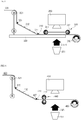
- FIG. 3 is a schematic view briefly showing a process of cleaning a protective film using a protective film cleaning device according to another exemplary embodiment of the present disclosure.
- a cleaning device for a protective film 200 includes a feed roll 221, guide rolls 225 and 227, a cleaning roll 240 having a nano thin film 242 formed on an outer surface thereof, a winding roll 260, a support frame 230, and sensors 251 and 253.
- the feed roll 221 of FIG. 3 may have a type which supplies the protective film 210 from one side without the protective film 210 being wound, but is not limited thereto, and the protective film 210 may be wound around the feed roll 221.
- a lower side of the feed roll 221 may be connected to the guide rolls 225 and 227 in order to change a movement direction of the protective film 210 to be vertical.
- the movement direction of the protective film 210 may be changed. While being changed the movement direction of the protective film 210, large particles of the foreign substances may be unforcedly removed.
- the movement direction of the protective film 210 must be changed again toward the support frame 230, and the guide roll 227 may thus be formed.
- FIG. 4 is a schematic view briefly showing a process of stopping a movement of a protective film in the state in FIG. 3 and then removing foreign substances on the protective film as a cleaning roll moves.
- the foreign substances remaining on the protective film 210 may be removed by being adsorbed by the nano thin film 242 of the cleaning roll 240.
- the feed roll 221 or the winding roll 260 may not rotate in a direction opposite to a direction in which the protective film 210 is wound by the winding roll 260, which is an original movement direction of the protective film 210.
- the rotation of the feed roll 221 and the winding roll 260 may be stopped and only the cleaning roll 240 may be reciprocally rotated so that the foreign substances remaining on the protective film 210 may be adsorbed.
- FIG. 3 shows the cleaning roll 240 in its regular position
- FIG. 4 shows the cleaning roll 240 rotating and moving along the upper surface of the protective film 210, and the cleaning roll 240 moves again to the regular position shown in FIG. 3 .
- the number of times the cleaning roll 240 reciprocally rotates and moves is freely controllable in accordance with the operator's choice or a removal state of the foreign substances.
- FIG. 5 is a schematic view briefly showing a process of cleaning a protective film using a protective film cleaning device according to another exemplary embodiment of the present disclosure.
- a cleaning device for a protective film 300 may be constructed in the same manner as in the above-described embodiments, with exception for the cleaning roll 340.
- a plurality of cleaning rolls 340 may be fixed to a support frame 330, and while rotating in a fixed state, foreign substances may be adsorbed by nano thin films on outer surfaces of cleaning rolls 341 and 342.
- a first cleaning roll 341 and a second cleaning roll 342 are disposed in sequence with respect to the movement direction of of the protective film 310 moving from a feed roll 321 to a winding roll 360.
- a size of the foreign substances adsorbed on the nano thin film of the first cleaning roll 341 may be larger than a size of the foreign substances adsorbed on the nano thin film of the second cleaning roll 342.
- first cleaning roll 341 and the second cleaning roll 342 having nano thin films for adsorbing foreign particles of different sizes, coarse and large particles are first adsorbed by the first cleaning roll 341 and smaller particles are adsorbed by the second cleaning roll 342, thereby increasing cleaning efficiency.
- FIG. 6 is a schematic view briefly showing a process of cleaning a protective film using a protective film cleaning device according to another exemplary embodiment of the present disclosure.
- cleaning rolls 440 may be formed in a straight line in a vertical direction with a protective film 410 interposed therebetween.
- a protective film 410 interposed therebetween.
Landscapes
- Engineering & Computer Science (AREA)
- Manufacturing & Machinery (AREA)
- Chemical & Material Sciences (AREA)
- Chemical Kinetics & Catalysis (AREA)
- Electrochemistry (AREA)
- General Chemical & Material Sciences (AREA)
- Cleaning In General (AREA)
Applications Claiming Priority (3)
| Application Number | Priority Date | Filing Date | Title |
|---|---|---|---|
| KR20160161266 | 2016-11-30 | ||
| KR1020170160256A KR102104297B1 (ko) | 2016-11-30 | 2017-11-28 | 세정 롤이 구비되어 있는 전지셀 제조용 보호 필름의 세정 장치 |
| PCT/KR2017/013771 WO2018101725A1 (ko) | 2016-11-30 | 2017-11-29 | 세정 롤이 구비되어 있는 전지셀 제조용 보호 필름의 세정 장치 |
Publications (3)
| Publication Number | Publication Date |
|---|---|
| EP3399581A1 true EP3399581A1 (de) | 2018-11-07 |
| EP3399581A4 EP3399581A4 (de) | 2019-01-09 |
| EP3399581B1 EP3399581B1 (de) | 2022-02-16 |
Family
ID=62241583
Family Applications (1)
| Application Number | Title | Priority Date | Filing Date |
|---|---|---|---|
| EP17875608.6A Active EP3399581B1 (de) | 2016-11-30 | 2017-11-29 | Reinigungsvorrichtung, mit einer reinigungsrolle, für schutzfilm zur batteriezellenherstellung |
Country Status (2)
| Country | Link |
|---|---|
| EP (1) | EP3399581B1 (de) |
| WO (1) | WO2018101725A1 (de) |
Families Citing this family (2)
| Publication number | Priority date | Publication date | Assignee | Title |
|---|---|---|---|---|
| CN110420934A (zh) * | 2019-08-06 | 2019-11-08 | 速博达(深圳)自动化有限公司 | 一种除尘装置、电池极片清洗机及电池生产设备 |
| CN115799597A (zh) * | 2023-01-06 | 2023-03-14 | 深圳市兴禾自动化股份有限公司 | 极片热复合机构和极片加工设备 |
Family Cites Families (11)
| Publication number | Priority date | Publication date | Assignee | Title |
|---|---|---|---|---|
| JP3005705B2 (ja) * | 1994-08-08 | 2000-02-07 | テクノロール 株式会社 | 粘着ゴミ取り装置 |
| US6523208B1 (en) * | 2000-03-24 | 2003-02-25 | Xerox Corporation | Flexible web cleaning system |
| JP2001321732A (ja) * | 2000-05-16 | 2001-11-20 | Funai Electric Co Ltd | タッチパネルの清掃機構、タッチパネルの清掃方法、および、表示装置 |
| WO2005009633A1 (en) * | 2003-07-22 | 2005-02-03 | Arizona Board Of Regents | System and method of dry contract cleaning for removing particles from semiconductor wafers |
| US20100175716A1 (en) * | 2006-08-11 | 2010-07-15 | Nitto Denko Corporation | Cleaning Member, Delivery Member with Cleaning Function, and Method of Cleaning Substrate Processing Apparatus |
| DE102006051313A1 (de) * | 2006-10-31 | 2008-05-08 | Robert Bosch Gmbh | Verfahren zur Erkennung von Verunreinigungen auf einer Oberfläche |
| JP4388986B2 (ja) * | 2008-03-19 | 2009-12-24 | シャープ株式会社 | シート積層体の清掃装置およびシート積層体の清掃方法 |
| KR101355834B1 (ko) * | 2010-12-02 | 2014-01-28 | 주식회사 엘지화학 | 이차전지 제조용 라미네이션 장치 |
| WO2012155215A1 (en) * | 2011-05-19 | 2012-11-22 | Automation Concepts & Solutions Pty Ltd | Improved apparatus for dry cleaning of layer pads |
| JP2013003436A (ja) * | 2011-06-20 | 2013-01-07 | Sumitomo Chemical Co Ltd | 異物除去方法 |
| KR101677974B1 (ko) * | 2014-12-15 | 2016-11-21 | (주)에이앤티 | 실리콘을 이용한 이물 포집용 점착 롤러 및 이물 포집용 점착 매트 |
-
2017
- 2017-11-29 EP EP17875608.6A patent/EP3399581B1/de active Active
- 2017-11-29 WO PCT/KR2017/013771 patent/WO2018101725A1/ko active Application Filing
Also Published As
| Publication number | Publication date |
|---|---|
| WO2018101725A1 (ko) | 2018-06-07 |
| EP3399581A4 (de) | 2019-01-09 |
| EP3399581B1 (de) | 2022-02-16 |
Similar Documents
| Publication | Publication Date | Title |
|---|---|---|
| US10974285B2 (en) | Device comprising cleaning roll and for cleaning protective film for preparing battery cell | |
| KR102256378B1 (ko) | 이차전지의 셀 스택 제조 시스템 및 방법 | |
| US11101490B2 (en) | Apparatus and method for manufacturing electrode assembly and electrode assembly manufactured using the same | |
| US20150333361A1 (en) | Secondary battery manufacturing method and manufacturing apparatus | |
| KR20170117681A (ko) | 전지셀에 접착테이프를 부착 가능한 테이핑 장치 | |
| KR20230122050A (ko) | 2차 배터리용 전극 조립체의 제조를 위한 방법 및 장치 | |
| CN110165274B (zh) | 方形二次电池用堆栈制造装置 | |
| EP3399581B1 (de) | Reinigungsvorrichtung, mit einer reinigungsrolle, für schutzfilm zur batteriezellenherstellung | |
| KR101429132B1 (ko) | 극판 와인딩장치 및 이를 사용하여 제조되는 전지셀 | |
| KR101572720B1 (ko) | 전극조립체의 권취장치 | |
| KR102414044B1 (ko) | 전지 셀에 부착 가능한 접착 테이프용 테이핑 장치 및 테이핑 방법 | |
| KR101040704B1 (ko) | 이차전지용 스택 제작장치 | |
| KR20210119787A (ko) | 단위 셀 제조 장치 및 방법 | |
| KR101963739B1 (ko) | 적층형 2차전지의 분리막 마감장치 | |
| KR102370758B1 (ko) | 이차전지용 셀스택 제조장치의 분리막 공급시스템 | |
| KR102253132B1 (ko) | 2차 전지용 단위 셀 제조 방법, 장치 및 시스템 | |
| KR20220154582A (ko) | 전극조립체 제조장치의 스윙 모듈 | |
| KR20130120745A (ko) | 이차전지용 전극의 롤프레스 시스템 | |
| EP3747548B1 (de) | Vorrichtung zur herstellung einer elektrodenanordnung mit luftreinigungsfunktion | |
| KR102273330B1 (ko) | 2차 전지용 전극 생산 시스템의 스태킹 장치 | |
| EP4254580A1 (de) | Vorrichtung zum stapeln von elektrodenplatten mit drehbarer abwickelvorrichtung für den separator | |
| KR102608817B1 (ko) | 이차전지 제조용 히팅 롤러 유니트 및 이를 갖는 이차전지스태킹 설비 | |
| KR102637366B1 (ko) | 셀 스택 제조장치의 분리막 컷팅유닛 | |
| CN219378077U (zh) | 一种极片分离装置和排废系统 | |
| KR102043114B1 (ko) | 2차전지셀 전극리드탭의 용접 가이드 장치 |
Legal Events
| Date | Code | Title | Description |
|---|---|---|---|
| STAA | Information on the status of an ep patent application or granted ep patent |
Free format text: STATUS: THE INTERNATIONAL PUBLICATION HAS BEEN MADE |
|
| PUAI | Public reference made under article 153(3) epc to a published international application that has entered the european phase |
Free format text: ORIGINAL CODE: 0009012 |
|
| STAA | Information on the status of an ep patent application or granted ep patent |
Free format text: STATUS: REQUEST FOR EXAMINATION WAS MADE |
|
| 17P | Request for examination filed |
Effective date: 20180731 |
|
| AK | Designated contracting states |
Kind code of ref document: A1 Designated state(s): AL AT BE BG CH CY CZ DE DK EE ES FI FR GB GR HR HU IE IS IT LI LT LU LV MC MK MT NL NO PL PT RO RS SE SI SK SM TR |
|
| AX | Request for extension of the european patent |
Extension state: BA ME |
|
| A4 | Supplementary search report drawn up and despatched |
Effective date: 20181207 |
|
| RIC1 | Information provided on ipc code assigned before grant |
Ipc: B08B 1/02 20060101ALI20181130BHEP Ipc: H01M 10/04 20060101AFI20181130BHEP Ipc: B08B 1/04 20060101ALI20181130BHEP Ipc: H01M 10/058 20100101ALI20181130BHEP |
|
| STAA | Information on the status of an ep patent application or granted ep patent |
Free format text: STATUS: REQUEST FOR EXAMINATION WAS MADE |
|
| DAV | Request for validation of the european patent (deleted) | ||
| DAX | Request for extension of the european patent (deleted) | ||
| GRAP | Despatch of communication of intention to grant a patent |
Free format text: ORIGINAL CODE: EPIDOSNIGR1 |
|
| STAA | Information on the status of an ep patent application or granted ep patent |
Free format text: STATUS: GRANT OF PATENT IS INTENDED |
|
| INTG | Intention to grant announced |
Effective date: 20211109 |
|
| GRAS | Grant fee paid |
Free format text: ORIGINAL CODE: EPIDOSNIGR3 |
|
| GRAA | (expected) grant |
Free format text: ORIGINAL CODE: 0009210 |
|
| STAA | Information on the status of an ep patent application or granted ep patent |
Free format text: STATUS: THE PATENT HAS BEEN GRANTED |
|
| RAP1 | Party data changed (applicant data changed or rights of an application transferred) |
Owner name: LG ENERGY SOLUTION LTD. |
|
| AK | Designated contracting states |
Kind code of ref document: B1 Designated state(s): AL AT BE BG CH CY CZ DE DK EE ES FI FR GB GR HR HU IE IS IT LI LT LU LV MC MK MT NL NO PL PT RO RS SE SI SK SM TR |
|
| REG | Reference to a national code |
Ref country code: GB Ref legal event code: FG4D |
|
| REG | Reference to a national code |
Ref country code: CH Ref legal event code: EP |
|
| REG | Reference to a national code |
Ref country code: DE Ref legal event code: R096 Ref document number: 602017053555 Country of ref document: DE |
|
| REG | Reference to a national code |
Ref country code: AT Ref legal event code: REF Ref document number: 1469457 Country of ref document: AT Kind code of ref document: T Effective date: 20220315 |
|
| REG | Reference to a national code |
Ref country code: IE Ref legal event code: FG4D |
|
| RAP4 | Party data changed (patent owner data changed or rights of a patent transferred) |
Owner name: LG ENERGY SOLUTION, LTD. |
|
| REG | Reference to a national code |
Ref country code: LT Ref legal event code: MG9D |
|
| REG | Reference to a national code |
Ref country code: NL Ref legal event code: MP Effective date: 20220216 |
|
| REG | Reference to a national code |
Ref country code: AT Ref legal event code: MK05 Ref document number: 1469457 Country of ref document: AT Kind code of ref document: T Effective date: 20220216 |
|
| PG25 | Lapsed in a contracting state [announced via postgrant information from national office to epo] |
Ref country code: SE Free format text: LAPSE BECAUSE OF FAILURE TO SUBMIT A TRANSLATION OF THE DESCRIPTION OR TO PAY THE FEE WITHIN THE PRESCRIBED TIME-LIMIT Effective date: 20220216 Ref country code: RS Free format text: LAPSE BECAUSE OF FAILURE TO SUBMIT A TRANSLATION OF THE DESCRIPTION OR TO PAY THE FEE WITHIN THE PRESCRIBED TIME-LIMIT Effective date: 20220216 Ref country code: PT Free format text: LAPSE BECAUSE OF FAILURE TO SUBMIT A TRANSLATION OF THE DESCRIPTION OR TO PAY THE FEE WITHIN THE PRESCRIBED TIME-LIMIT Effective date: 20220616 Ref country code: NO Free format text: LAPSE BECAUSE OF FAILURE TO SUBMIT A TRANSLATION OF THE DESCRIPTION OR TO PAY THE FEE WITHIN THE PRESCRIBED TIME-LIMIT Effective date: 20220516 Ref country code: NL Free format text: LAPSE BECAUSE OF FAILURE TO SUBMIT A TRANSLATION OF THE DESCRIPTION OR TO PAY THE FEE WITHIN THE PRESCRIBED TIME-LIMIT Effective date: 20220216 Ref country code: LT Free format text: LAPSE BECAUSE OF FAILURE TO SUBMIT A TRANSLATION OF THE DESCRIPTION OR TO PAY THE FEE WITHIN THE PRESCRIBED TIME-LIMIT Effective date: 20220216 Ref country code: HR Free format text: LAPSE BECAUSE OF FAILURE TO SUBMIT A TRANSLATION OF THE DESCRIPTION OR TO PAY THE FEE WITHIN THE PRESCRIBED TIME-LIMIT Effective date: 20220216 Ref country code: ES Free format text: LAPSE BECAUSE OF FAILURE TO SUBMIT A TRANSLATION OF THE DESCRIPTION OR TO PAY THE FEE WITHIN THE PRESCRIBED TIME-LIMIT Effective date: 20220216 Ref country code: BG Free format text: LAPSE BECAUSE OF FAILURE TO SUBMIT A TRANSLATION OF THE DESCRIPTION OR TO PAY THE FEE WITHIN THE PRESCRIBED TIME-LIMIT Effective date: 20220516 |
|
| PG25 | Lapsed in a contracting state [announced via postgrant information from national office to epo] |
Ref country code: PL Free format text: LAPSE BECAUSE OF FAILURE TO SUBMIT A TRANSLATION OF THE DESCRIPTION OR TO PAY THE FEE WITHIN THE PRESCRIBED TIME-LIMIT Effective date: 20220216 Ref country code: LV Free format text: LAPSE BECAUSE OF FAILURE TO SUBMIT A TRANSLATION OF THE DESCRIPTION OR TO PAY THE FEE WITHIN THE PRESCRIBED TIME-LIMIT Effective date: 20220216 Ref country code: GR Free format text: LAPSE BECAUSE OF FAILURE TO SUBMIT A TRANSLATION OF THE DESCRIPTION OR TO PAY THE FEE WITHIN THE PRESCRIBED TIME-LIMIT Effective date: 20220517 Ref country code: FI Free format text: LAPSE BECAUSE OF FAILURE TO SUBMIT A TRANSLATION OF THE DESCRIPTION OR TO PAY THE FEE WITHIN THE PRESCRIBED TIME-LIMIT Effective date: 20220216 Ref country code: AT Free format text: LAPSE BECAUSE OF FAILURE TO SUBMIT A TRANSLATION OF THE DESCRIPTION OR TO PAY THE FEE WITHIN THE PRESCRIBED TIME-LIMIT Effective date: 20220216 |
|
| PG25 | Lapsed in a contracting state [announced via postgrant information from national office to epo] |
Ref country code: IS Free format text: LAPSE BECAUSE OF FAILURE TO SUBMIT A TRANSLATION OF THE DESCRIPTION OR TO PAY THE FEE WITHIN THE PRESCRIBED TIME-LIMIT Effective date: 20220617 |
|
| PG25 | Lapsed in a contracting state [announced via postgrant information from national office to epo] |
Ref country code: SM Free format text: LAPSE BECAUSE OF FAILURE TO SUBMIT A TRANSLATION OF THE DESCRIPTION OR TO PAY THE FEE WITHIN THE PRESCRIBED TIME-LIMIT Effective date: 20220216 Ref country code: SK Free format text: LAPSE BECAUSE OF FAILURE TO SUBMIT A TRANSLATION OF THE DESCRIPTION OR TO PAY THE FEE WITHIN THE PRESCRIBED TIME-LIMIT Effective date: 20220216 Ref country code: RO Free format text: LAPSE BECAUSE OF FAILURE TO SUBMIT A TRANSLATION OF THE DESCRIPTION OR TO PAY THE FEE WITHIN THE PRESCRIBED TIME-LIMIT Effective date: 20220216 Ref country code: EE Free format text: LAPSE BECAUSE OF FAILURE TO SUBMIT A TRANSLATION OF THE DESCRIPTION OR TO PAY THE FEE WITHIN THE PRESCRIBED TIME-LIMIT Effective date: 20220216 Ref country code: DK Free format text: LAPSE BECAUSE OF FAILURE TO SUBMIT A TRANSLATION OF THE DESCRIPTION OR TO PAY THE FEE WITHIN THE PRESCRIBED TIME-LIMIT Effective date: 20220216 Ref country code: CZ Free format text: LAPSE BECAUSE OF FAILURE TO SUBMIT A TRANSLATION OF THE DESCRIPTION OR TO PAY THE FEE WITHIN THE PRESCRIBED TIME-LIMIT Effective date: 20220216 |
|
| REG | Reference to a national code |
Ref country code: DE Ref legal event code: R097 Ref document number: 602017053555 Country of ref document: DE |
|
| PG25 | Lapsed in a contracting state [announced via postgrant information from national office to epo] |
Ref country code: AL Free format text: LAPSE BECAUSE OF FAILURE TO SUBMIT A TRANSLATION OF THE DESCRIPTION OR TO PAY THE FEE WITHIN THE PRESCRIBED TIME-LIMIT Effective date: 20220216 |
|
| PLBE | No opposition filed within time limit |
Free format text: ORIGINAL CODE: 0009261 |
|
| STAA | Information on the status of an ep patent application or granted ep patent |
Free format text: STATUS: NO OPPOSITION FILED WITHIN TIME LIMIT |
|
| 26N | No opposition filed |
Effective date: 20221117 |
|
| PG25 | Lapsed in a contracting state [announced via postgrant information from national office to epo] |
Ref country code: SI Free format text: LAPSE BECAUSE OF FAILURE TO SUBMIT A TRANSLATION OF THE DESCRIPTION OR TO PAY THE FEE WITHIN THE PRESCRIBED TIME-LIMIT Effective date: 20220216 |
|
| P01 | Opt-out of the competence of the unified patent court (upc) registered |
Effective date: 20230512 |
|
| PG25 | Lapsed in a contracting state [announced via postgrant information from national office to epo] |
Ref country code: MC Free format text: LAPSE BECAUSE OF FAILURE TO SUBMIT A TRANSLATION OF THE DESCRIPTION OR TO PAY THE FEE WITHIN THE PRESCRIBED TIME-LIMIT Effective date: 20220216 |
|
| REG | Reference to a national code |
Ref country code: CH Ref legal event code: PL |
|
| REG | Reference to a national code |
Ref country code: BE Ref legal event code: MM Effective date: 20221130 |
|
| PG25 | Lapsed in a contracting state [announced via postgrant information from national office to epo] |
Ref country code: LI Free format text: LAPSE BECAUSE OF NON-PAYMENT OF DUE FEES Effective date: 20221130 Ref country code: IT Free format text: LAPSE BECAUSE OF FAILURE TO SUBMIT A TRANSLATION OF THE DESCRIPTION OR TO PAY THE FEE WITHIN THE PRESCRIBED TIME-LIMIT Effective date: 20220216 Ref country code: CH Free format text: LAPSE BECAUSE OF NON-PAYMENT OF DUE FEES Effective date: 20221130 |
|
| PG25 | Lapsed in a contracting state [announced via postgrant information from national office to epo] |
Ref country code: LU Free format text: LAPSE BECAUSE OF NON-PAYMENT OF DUE FEES Effective date: 20221129 |
|
| PG25 | Lapsed in a contracting state [announced via postgrant information from national office to epo] |
Ref country code: IE Free format text: LAPSE BECAUSE OF NON-PAYMENT OF DUE FEES Effective date: 20221129 |
|
| PG25 | Lapsed in a contracting state [announced via postgrant information from national office to epo] |
Ref country code: BE Free format text: LAPSE BECAUSE OF NON-PAYMENT OF DUE FEES Effective date: 20221130 |
|
| PGFP | Annual fee paid to national office [announced via postgrant information from national office to epo] |
Ref country code: GB Payment date: 20231023 Year of fee payment: 7 |
|
| PGFP | Annual fee paid to national office [announced via postgrant information from national office to epo] |
Ref country code: FR Payment date: 20231024 Year of fee payment: 7 Ref country code: DE Payment date: 20231023 Year of fee payment: 7 |
|
| PG25 | Lapsed in a contracting state [announced via postgrant information from national office to epo] |
Ref country code: HU Free format text: LAPSE BECAUSE OF FAILURE TO SUBMIT A TRANSLATION OF THE DESCRIPTION OR TO PAY THE FEE WITHIN THE PRESCRIBED TIME-LIMIT; INVALID AB INITIO Effective date: 20171129 |
|
| PG25 | Lapsed in a contracting state [announced via postgrant information from national office to epo] |
Ref country code: CY Free format text: LAPSE BECAUSE OF FAILURE TO SUBMIT A TRANSLATION OF THE DESCRIPTION OR TO PAY THE FEE WITHIN THE PRESCRIBED TIME-LIMIT Effective date: 20220216 |