EP3399298A1 - Smoking machine for electronic cigarette - Google Patents
Smoking machine for electronic cigarette Download PDFInfo
- Publication number
- EP3399298A1 EP3399298A1 EP16881178.4A EP16881178A EP3399298A1 EP 3399298 A1 EP3399298 A1 EP 3399298A1 EP 16881178 A EP16881178 A EP 16881178A EP 3399298 A1 EP3399298 A1 EP 3399298A1
- Authority
- EP
- European Patent Office
- Prior art keywords
- cigarette
- catcher
- smoking
- electronic cigarette
- housing
- Prior art date
- Legal status (The legal status is an assumption and is not a legal conclusion. Google has not performed a legal analysis and makes no representation as to the accuracy of the status listed.)
- Granted
Links
- 230000000391 smoking effect Effects 0.000 title claims abstract description 318
- 239000003571 electronic cigarette Substances 0.000 title claims abstract description 315
- 235000019504 cigarettes Nutrition 0.000 claims abstract description 266
- 238000007789 sealing Methods 0.000 claims abstract description 115
- 238000009423 ventilation Methods 0.000 claims abstract description 44
- 230000000149 penetrating effect Effects 0.000 claims abstract description 10
- 230000007246 mechanism Effects 0.000 claims description 80
- 238000003860 storage Methods 0.000 claims description 77
- 238000005303 weighing Methods 0.000 claims description 57
- 239000000779 smoke Substances 0.000 claims description 34
- 238000004891 communication Methods 0.000 claims description 32
- 230000005540 biological transmission Effects 0.000 claims description 29
- 238000003825 pressing Methods 0.000 claims description 20
- 238000002360 preparation method Methods 0.000 claims description 19
- 238000012546 transfer Methods 0.000 claims description 6
- 238000000034 method Methods 0.000 abstract description 41
- 241000208125 Nicotiana Species 0.000 abstract description 38
- 235000002637 Nicotiana tabacum Nutrition 0.000 abstract description 38
- 230000008569 process Effects 0.000 abstract description 29
- 238000000889 atomisation Methods 0.000 abstract description 19
- 238000002474 experimental method Methods 0.000 abstract description 15
- 229920000742 Cotton Polymers 0.000 abstract description 7
- 238000010586 diagram Methods 0.000 description 28
- 238000012360 testing method Methods 0.000 description 16
- 238000001514 detection method Methods 0.000 description 15
- 238000009413 insulation Methods 0.000 description 14
- 230000008859 change Effects 0.000 description 12
- 239000000463 material Substances 0.000 description 12
- 230000009471 action Effects 0.000 description 11
- 239000000443 aerosol Substances 0.000 description 9
- 239000011152 fibreglass Substances 0.000 description 9
- 230000000694 effects Effects 0.000 description 8
- 238000010438 heat treatment Methods 0.000 description 7
- 230000001960 triggered effect Effects 0.000 description 7
- 238000005259 measurement Methods 0.000 description 6
- 230000005484 gravity Effects 0.000 description 5
- 238000005452 bending Methods 0.000 description 4
- 230000008021 deposition Effects 0.000 description 4
- 230000009286 beneficial effect Effects 0.000 description 3
- 230000008901 benefit Effects 0.000 description 3
- 238000013461 design Methods 0.000 description 3
- 238000012986 modification Methods 0.000 description 3
- 230000004048 modification Effects 0.000 description 3
- 238000011160 research Methods 0.000 description 3
- 238000012827 research and development Methods 0.000 description 3
- 230000006399 behavior Effects 0.000 description 2
- 238000009833 condensation Methods 0.000 description 2
- 230000005494 condensation Effects 0.000 description 2
- 238000004519 manufacturing process Methods 0.000 description 2
- 230000002093 peripheral effect Effects 0.000 description 2
- 230000001105 regulatory effect Effects 0.000 description 2
- 230000004936 stimulating effect Effects 0.000 description 2
- SNICXCGAKADSCV-JTQLQIEISA-N (-)-Nicotine Chemical compound CN1CCC[C@H]1C1=CC=CN=C1 SNICXCGAKADSCV-JTQLQIEISA-N 0.000 description 1
- 244000061176 Nicotiana tabacum Species 0.000 description 1
- 230000003044 adaptive effect Effects 0.000 description 1
- 239000003795 chemical substances by application Substances 0.000 description 1
- 239000000470 constituent Substances 0.000 description 1
- 230000001276 controlling effect Effects 0.000 description 1
- 238000013480 data collection Methods 0.000 description 1
- 230000003247 decreasing effect Effects 0.000 description 1
- 238000011161 development Methods 0.000 description 1
- 238000011026 diafiltration Methods 0.000 description 1
- 238000007599 discharging Methods 0.000 description 1
- 230000005611 electricity Effects 0.000 description 1
- 239000004615 ingredient Substances 0.000 description 1
- 239000007788 liquid Substances 0.000 description 1
- 229960002715 nicotine Drugs 0.000 description 1
- SNICXCGAKADSCV-UHFFFAOYSA-N nicotine Natural products CN1CCCC1C1=CC=CN=C1 SNICXCGAKADSCV-UHFFFAOYSA-N 0.000 description 1
- 238000003908 quality control method Methods 0.000 description 1
- 238000010998 test method Methods 0.000 description 1
- 235000019505 tobacco product Nutrition 0.000 description 1
- 230000009466 transformation Effects 0.000 description 1
- 239000002699 waste material Substances 0.000 description 1
Images


Classifications
-
- A—HUMAN NECESSITIES
- A24—TOBACCO; CIGARS; CIGARETTES; SIMULATED SMOKING DEVICES; SMOKERS' REQUISITES
- A24F—SMOKERS' REQUISITES; MATCH BOXES; SIMULATED SMOKING DEVICES
- A24F40/00—Electrically operated smoking devices; Component parts thereof; Manufacture thereof; Maintenance or testing thereof; Charging means specially adapted therefor
- A24F40/80—Testing
-
- A—HUMAN NECESSITIES
- A24—TOBACCO; CIGARS; CIGARETTES; SIMULATED SMOKING DEVICES; SMOKERS' REQUISITES
- A24F—SMOKERS' REQUISITES; MATCH BOXES; SIMULATED SMOKING DEVICES
- A24F40/00—Electrically operated smoking devices; Component parts thereof; Manufacture thereof; Maintenance or testing thereof; Charging means specially adapted therefor
- A24F40/40—Constructional details, e.g. connection of cartridges and battery parts
- A24F40/42—Cartridges or containers for inhalable precursors
-
- A—HUMAN NECESSITIES
- A24—TOBACCO; CIGARS; CIGARETTES; SIMULATED SMOKING DEVICES; SMOKERS' REQUISITES
- A24C—MACHINES FOR MAKING CIGARS OR CIGARETTES
- A24C5/00—Making cigarettes; Making tipping materials for, or attaching filters or mouthpieces to, cigars or cigarettes
- A24C5/32—Separating, ordering, counting or examining cigarettes; Regulating the feeding of tobacco according to rod or cigarette condition
- A24C5/34—Examining cigarettes or the rod, e.g. for regulating the feeding of tobacco; Removing defective cigarettes
- A24C5/3406—Controlling cigarette combustion
-
- A—HUMAN NECESSITIES
- A24—TOBACCO; CIGARS; CIGARETTES; SIMULATED SMOKING DEVICES; SMOKERS' REQUISITES
- A24F—SMOKERS' REQUISITES; MATCH BOXES; SIMULATED SMOKING DEVICES
- A24F40/00—Electrically operated smoking devices; Component parts thereof; Manufacture thereof; Maintenance or testing thereof; Charging means specially adapted therefor
- A24F40/50—Control or monitoring
- A24F40/51—Arrangement of sensors
-
- A—HUMAN NECESSITIES
- A61—MEDICAL OR VETERINARY SCIENCE; HYGIENE
- A61M—DEVICES FOR INTRODUCING MEDIA INTO, OR ONTO, THE BODY; DEVICES FOR TRANSDUCING BODY MEDIA OR FOR TAKING MEDIA FROM THE BODY; DEVICES FOR PRODUCING OR ENDING SLEEP OR STUPOR
- A61M15/00—Inhalators
- A61M15/06—Inhaling appliances shaped like cigars, cigarettes or pipes
-
- G—PHYSICS
- G01—MEASURING; TESTING
- G01M—TESTING STATIC OR DYNAMIC BALANCE OF MACHINES OR STRUCTURES; TESTING OF STRUCTURES OR APPARATUS, NOT OTHERWISE PROVIDED FOR
- G01M99/00—Subject matter not provided for in other groups of this subclass
- G01M99/005—Testing of complete machines, e.g. washing-machines or mobile phones
-
- G—PHYSICS
- G01—MEASURING; TESTING
- G01N—INVESTIGATING OR ANALYSING MATERIALS BY DETERMINING THEIR CHEMICAL OR PHYSICAL PROPERTIES
- G01N1/00—Sampling; Preparing specimens for investigation
- G01N1/02—Devices for withdrawing samples
- G01N1/22—Devices for withdrawing samples in the gaseous state
- G01N1/24—Suction devices
-
- G—PHYSICS
- G01—MEASURING; TESTING
- G01N—INVESTIGATING OR ANALYSING MATERIALS BY DETERMINING THEIR CHEMICAL OR PHYSICAL PROPERTIES
- G01N5/00—Analysing materials by weighing, e.g. weighing small particles separated from a gas or liquid
-
- A—HUMAN NECESSITIES
- A24—TOBACCO; CIGARS; CIGARETTES; SIMULATED SMOKING DEVICES; SMOKERS' REQUISITES
- A24F—SMOKERS' REQUISITES; MATCH BOXES; SIMULATED SMOKING DEVICES
- A24F40/00—Electrically operated smoking devices; Component parts thereof; Manufacture thereof; Maintenance or testing thereof; Charging means specially adapted therefor
- A24F40/10—Devices using liquid inhalable precursors
-
- A—HUMAN NECESSITIES
- A61—MEDICAL OR VETERINARY SCIENCE; HYGIENE
- A61M—DEVICES FOR INTRODUCING MEDIA INTO, OR ONTO, THE BODY; DEVICES FOR TRANSDUCING BODY MEDIA OR FOR TAKING MEDIA FROM THE BODY; DEVICES FOR PRODUCING OR ENDING SLEEP OR STUPOR
- A61M2205/00—General characteristics of the apparatus
- A61M2205/82—Internal energy supply devices
- A61M2205/8206—Internal energy supply devices battery-operated
-
- G—PHYSICS
- G01—MEASURING; TESTING
- G01N—INVESTIGATING OR ANALYSING MATERIALS BY DETERMINING THEIR CHEMICAL OR PHYSICAL PROPERTIES
- G01N1/00—Sampling; Preparing specimens for investigation
- G01N1/02—Devices for withdrawing samples
- G01N2001/028—Sampling from a surface, swabbing, vaporising
Definitions
- the present invention relates to the technical field of electronic cigarettes, and in particular to a smoking machine for an electronic cigarette.
- An electronic cigarette is a new type of product. Different from a cigarette manufactured by using conventional tobacco and smoked through lighting, currently, main electronic cigarette products atomize tobacco tar through electrical heating and turns aerosol agent, odorous constituents, and nicotine in the tobacco tar into an aerosol state, so as to simulate an effect of cigarette smoke for inhaling by a consumer and the consumer will obtain a satisfactory feeling. Because the electronic cigarette provides a consumption experience similar to that of a cigarette, and has extremely few harmful ingredients therein relative to the conventional tobacco, the electronic cigarette has become a representative developing direction of a new type of tobacco product. China is a cradle and a main manufacturing site of the electronic cigarette. Globally, 90% or more than 90% of electronic cigarettes are produced in China.
- an existing rotary-disc smoking machine has a rotary disc 81 that horizontally rotates.
- the rotary disc 81 is perpendicular to a horizontal plane with a rotary axis 84 as a central line.
- Several cigarette clamps are evenly arranged on the rotary disc 81 along a periphery of the rotary disc 81.
- a cigarette is inserted into a cigarette clamp 82, and the rotary disc 81 horizontally rotates.
- An axial central line of the cigarette is perpendicular to the rotary axis 84.
- smoke is transmitted to a catcher in the rotary-disc smoking machine from a smoke transmission bending pipe 83 of 90 degrees behind the cigarette clamp 82.
- each smoking hole channel 85 is linearly arranged.
- Each smoking hole channel 85 is provided with a cigarette clamp correspondingly.
- Each smoking hole channel 85 is connected to an independent smoking unit. When several cigarettes are lit together, the cigarettes are synchronously smoked based on a smoking capacity defined by a standard.
- a control circuit is triggered by a switch manually or through pneumatic pressure and supplies power to a heating wire.
- a current enables the heating wire to generate a high temperature.
- a fiberglass oil guiding rope twisting inside the heating wire is affected by the high temperature and generates a wick effect.
- Tobacco tar is continuously transmitted to a high temperature end along the fiberglass oil guiding rope.
- the tobacco tar is instantly heated and vaporized into smoke.
- a smoker smokes by using a cigarette holder. Airflow enters from a vapor inlet hole, and vapor smoke generated in an atomization cavity is inhaled from the cigarette holder to obtain a feeling similar to cigarette smoking.
- the tobacco tar can flow in a storage cavity but is unevenly distributed.
- the electronic cigarette does not move on the existing linear smoking machine, but on the existing rotary-disc smoking machine, the electronic cigarette horizontally rotates.
- the tobacco tar is always deposited at a lower portion of a liquid storage cavity due to the gravity.
- the tobacco tar is consumed in a continuous test process.
- a great change may occur on atomization amount due to insufficient tobacco tar replenishment amount, and a smoke amount is decreased.
- different atomization results may be generated in an actual detection process.
- the tobacco tar replenishment amount and timeliness of replenishment cause a difference due to different detection devices or methods. Finally, a deviation and a larger error of a detection result are caused.
- Both of mechanisms of the two conventional smoking machines are not provided with a manually or linkage controlled pressing part, and do not have a function for testing a manually triggered electronic cigarette.
- the two smoking machines For automatic determination of smoking termination of a conventional cigarette, that is, position determination when the cigarette is completely burned, the two smoking machines use a method in which a cotton thread in close contact with the cigarette is burned away or an infrared sensing identification manner.
- An electronic cigarette has no lighting or extinguishment process, the smoking machine cannot directly judge online whether tobacco tar or a battery quantity of the electronic cigarette runs out, that is, a service life of the electronic cigarette.
- a cigarette cartridge portion of an electronic cigarette has a large tobacco tar storage capacity.
- a total aerosol releasing quantity after atomization far exceeds a catching capability of a single fiberglass Cambridge filter. Therefore, when quality stability performance of the electronic cigarette during continuous use is continuously tested, a filter catcher must be changed after several puffs are smoked.
- multiple catcher weighing actions may be added during catching of a single filter.
- an experiment process needs to be manually interrupted to change a catcher provided with a Cambridge filter. In this way, labor costs are inevitably increased, working efficiency is reduced, and a possibility of a deviation or error of an experiment result is increased to a great extent.
- a smoking machine for an electronic cigarette provided in the present invention resolves the following technical problems:
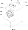
- the present invention provides a smoking machine for an electronic cigarette, comprising: a housing; a rotary disc installed on the housing, the rotary disc rotates relative to the housing with a central axis of the rotary disc as a center; at least one disc-body smoking through hole is provided on an end face of the rotary disc; a housing sealing member is disposed on the housing, a sealing ventilation hole penetrating into an inner portion of the housing is provided in the housing sealing member, and when the sealing ventilation hole is in communication with one end of a catcher, the other end of the catcher is in communication with a smoking apparatus; the central axis of the rotary disc is parallel to a horizontal plane; and at least one cigarette clamping mechanism, comprising a clamping mechanism body and a cigarette clamp disposed on the clamping mechanism body, wherein the cigarette clamp is installed on the disc-body smoking through hole of the rotary disc; one end of the cigarette clamp is a cigarette clamping end for inserting therein an electronic cigarette in a horizontal direction, the
- the central axis of the rotary disc consistent with the present invention is parallel to the horizontal plane, that is, a central line around which the rotary disc rotates is parallel to the horizontal plane.
- the rotary disc is provided with at least one disc-body smoking through hole.
- the disc-body smoking through hole passes through two end faces of the rotary disc.
- the disc-body smoking through hole is provided with the cigarette clamping mechanism for clamping the electronic cigarette.
- the axial through hole of the cigarette clamp on the cigarette clamping mechanism is disposed in the horizontal direction.
- the catcher is pushed to move in the horizontal direction to a smoking position, so that the catcher is in communication with the sealing ventilation hole of the housing sealing member. That is, during smoking, smoke enters the catcher in the horizontal direction from the axial through hole of the cigarette clamp and the sealing ventilation hole of the housing sealing member.
- the catcher and the electronic cigarette can be coaxially arranged, which remarkably reduces bumping condensation deposition of aerosol in a bending pipe of a conventional smoking machine, reduces transmission losses, is beneficial to correctness of smoke detection analysis, and resolves a technical problem that is difficult to solve for a conventional smoking machine during smoking of the electronic cigarette.
- the two or more disc-body smoking through holes are evenly arranged on the rotary disc, and distances between central axes of the disc-body smoking through holes and the central axis of the rotary disc are the same.
- this structure enables the axial through hole of the cigarette clamp to sequentially come into communication with the sealing ventilation hole of the housing sealing member.
- the housing sealing member is disposed on an upper portion of a side surface of the housing, and a central axis of the sealing ventilation hole and the central axis of the rotary disc both pass through a vertical plane perpendicular to the horizontal plane.
- the catcher is generally disposed inside from a top portion of the housing.
- the housing sealing member is disposed on an upper portion of the housing, and the central axis of the sealing ventilation hole and the central axis of the rotary disc pass through the vertical plane. This structure enables the axial through hole to move to a position close to the top portion of the housing and come into communication with the sealing ventilation hole of the housing sealing member.
- an end face of the housing sealing member is in contact with the end face of the rotary disc, and the end face of the rotary disc in contact with the housing sealing member is a plane. This facilitates the end face of the rotary disc and the sealing ventilation hole of the housing sealing member to be sealed during rotation of the rotary disc.
- the smoking machine for an electronic cigarette further comprises an automatic loading and weighing system of a catcher
- the automatic loading and weighing system of a catcher comprises: a temporary feeding storage store and a temporary discharge storage store, which are disposed on the housing of the smoking machine for an electronic cigarette and in communication with an inner portion of the housing; a transmission mechanism, a balance, an ejector pin assembly, and a discharge transferring mechanism, which are disposed inside the housing; and a main control circuit board electrically connected to the ejector pin assembly, the transmission mechanism, the temporary feeding storage store, the temporary discharge storage store, and the discharge transferring mechanism; the temporary feeding storage store receives the catcher disposed from an outer portion of the smoking machine for an electronic cigarette, and the catcher is taken out from the temporary discharge storage store; a robotic arm is installed on the transmission mechanism, the robotic arm obtains the catcher, the transmission mechanism drives the robotic arm to move, so that the catcher reaches a preparation position and a weighing position, and during moving of the catcher,
- the catcher is disposed inside the temporary feeding storage store from the outer portion of the smoking machine for an electronic cigarette.
- the main control circuit board controls the transmission mechanism to drive the robotic arm to move from the preparation position to a supporting position close to the bottom of the temporary feeding storage store.
- the preparation position is an initial zero position.
- the position is a reference position from which the robotic arm moves to other working positions and is used for calculating a moving distance.
- the main control circuit board controls the catcher in the temporary feeding storage store to fall on the robotic arm.
- the robotic arm carries the catcher and returns to the preparation position.
- the main control circuit board controls the ejector pin assembly to push the catcher to the smoking position, so that the catcher comes into connection to a smoking end of the electronic cigarette, and the vapor channel comes into communication with the catcher.
- the smoking apparatus sucks vapor from the electronic cigarette by using the vapor channel, and vapor smoke of the electronic cigarette is absorbed by the catcher.
- the main control circuit board controls the ejector pin assembly to contract.
- the main control circuit board controls the transmission mechanism to drive the catcher on the robotic arm to move to the weighing position of the balance and the balance weighs the catcher.
- the catcher is transmitted to a discharge position of the temporary discharge storage store by a discharge transferring mechanism.
- a ventilation direction of the catcher is always consistent with a smoking experiment direction of the electronic cigarette.
- the catcher drops material and cooperates with the robotic arm depending on the gravity, thereby ensuring that the catcher is quickly and stably changed within a smoking interval of two puffs.
- the catcher is always controlled by the robotic arm inside the smoking machine.
- the smoking position is quite close to the weighing position, so that the robotic arm can quickly move to a required position under control of the main control circuit board. This ensures that the catcher returns to the smoking position after a weighing action is completed within the smoking interval of two puffs.
- the discharge transferring mechanism comprises an inclined slideway for the catcher to slide and a discharge pushing cylinder.
- a horizontal height of an end of the inclined slideway close to the temporary discharge storage store is less than a horizontal height of an end of the inclined slideway far away from the temporary discharge storage store, the discharge pushing cylinder is disposed below the end of the inclined slideway close to the temporary discharge storage store, and a piston rod of the discharge pushing cylinder is located exactly below the temporary discharge storage store.
- the discharge transferring mechanism is provided with the inclined slideway.
- the robotic arm places the catcher at the end of the slideway far away from the temporary discharge storage store, the catcher slides along an inclined direction of the inclined slideway to the end of the inclined slideway close to the temporary discharge storage store.
- the piston rod of the discharge pushing cylinder is exactly below the catcher.
- the main control circuit board controls the piston rod of the discharge pushing cylinder to push the catcher in a vertical direction, so that the catcher can be quickly pushed to the discharge position of the temporary discharge storage store.
- the catcher comprises a catching body and a vapor guiding head disposed on each of two axial end faces of the catching body, the robotic arm is formed by two grippers with a V-shaped groove at an end portion, and the V-shaped groove supports the corresponding vapor guiding head.
- This structure enables the grippers of the robotic arm to stably support the vapor guiding head and facilitates the robotic arm to drive the catcher to move.
- the ejector pin assembly comprises an ejector pin cylinder and an adapter sealing member.
- the adapter sealing member is connected to a piston rod of the ejector pin cylinder, the vapor channel is disposed on the adapter sealing member, and when the catcher is located at the smoking position, the adapter sealing member is in sealing connection to a vapor outlet end of the catcher, and the vapor channel communicates the catcher with the smoking apparatus.
- This structure can quickly push the catcher to the smoking position and enable the catcher to be in sealing connection to the vapor channel.
- the smoking machine for an electronic cigarette further comprises an electronic cigarette triggering system
- the electronic cigarette triggering system comprises a cigarette triggering portion and a triggering control cylinder connected to the cigarette triggering portion, the cigarette triggering portion is able to come into contact with the electronic cigarette under control of the triggering control cylinder, the triggering control cylinder is fixed on a connection block, and the connection block is connected to the housing by using a connection structure.
- a dedicated electronic cigarette triggering system is installed on the housing, so that automatic control of electronic cigarette triggering is implemented, and a problem that an existing smoking machine does not have a manually triggered electronic cigarette triggering system and external power supply is resolved.
- the cigarette triggering portion comprises a negative contact terminal and a positive contact terminal
- the negative contact terminal corresponds to a position of a negative electrode of the electronic cigarette
- the positive contact terminal corresponds to a position of a positive electrode of the electronic cigarette
- the negative contact terminal and the positive contact terminal are connected to a current control apparatus.
- a steady direct current supplied by the current control apparatus of the smoking machine is used.
- Power is supplied to the cigarette cartridge connected to the electronic cigarette rod in a manner in which the positive contact terminal and the negative contact terminal are respectively in contact with the positive electrode and negative electrode of the electronic cigarette.
- parameters such as a voltage, a current, and power can be adjusted and set by using the current control apparatus, the temperature of a heating wire can be changed, atomization efficiency of tobacco tar under different electric quantities can be examined, and a technical basis is provided for research and development of a product.
- the cigarette triggering portion comprises a cigarette pressing terminal, and the cigarette pressing terminal corresponds to a position of a power-on button of the electronic cigarette.
- a pre-triggering time may be set pinpointing to a millisecond level, an advance amount of a specified triggering time may be implemented, thereby eliminating a delay problem of the triggering time and more accurately cooperating with a smoking starting time of the smoking machine.
- the clamping mechanism body comprises a horizontal base plate and a vertical supporting plate, an upper surface of the horizontal base plate is provided with a guiding groove, the guiding groove is disposed in a direction of the length of the horizontal base plate; and a bottom portion of the vertical supporting plate is connected to a rear end of the horizontal base plate, and the vertical supporting plate is provided with a base through hole penetrating in a horizontal direction; the other end of the cigarette clamp is a disc body connection end, and the disc body connection end penetrates into the base through hole of the vertical supporting plate; and the cigarette clamping mechanism further comprises a cigarette gripper, and the cigarette gripper comprises a gripper base plate and two side surface clamping portions disposed opposite to each other provided on the gripper base plate, the gripper base plate is installed on the guiding groove of the horizontal base plate and is movable in a direction of the length of the guiding groove, and the two side surface clamping portions are symmetrically disposed by using a vertical plane of a central axis of the
- the smoking end of a cigarette is inserted into the cigarette clamping end of the cigarette clamp. Since the two side surface clamping portions are symmetrically disposed by using a vertical plane of a central axis of the axial through hole as an axial plane, after the two side surface clamping portions disposed opposite to each other clamp side surfaces of the cigarette, a central axis of the cigarette can accurately align with the axial through hole on the cigarette clamp, keeping the cigarette airtight all the time after being inserted into the cigarette clamp and keeping a position of the cigarette to be stable.
- the gripper base plate is movable along the direction of the length of the guiding groove, a position at which the two side surface clamping portions clamp the cigarette can change based on a structure of the cigarette. This enables cigarette clamping mechanism consistent with the present invention to clamp cigarettes of various types.
- the rotary disc consistent with the present invention is perpendicular to the horizontal plane, and the electronic cigarette circumferentially rotates along with the rotary disc in a smoking experiment process, so that tobacco tar in a cigarette cartridge flows and fully immerses the oil guiding cotton, thus ensuring sufficient and steady supply of the tobacco tar to an atomizer, and guaranteeing atomization efficiency, atomization amount, and the stability and accuracy of experiment data.
- the cigarette clamping mechanism cooperates with a rotation direction of the rotary disc to stably clamp the electronic cigarette.
- the automatic loading and weighing system of the catcher cooperates with an operation direction of the rotary disc to control the catcher to move to a required position.
- a ventilation direction of the catcher is always consistent with a smoking experiment direction of the electronic cigarette. This can ensure that the catcher is quickly and stably changed during a smoking interval of two puffs, and can also ensure that the catcher returns to the smoking position after a weighing action is completed during the smoking interval of two puffs.
- the electronic cigarette triggering system consistent with the present invention implements automatic control of triggering of the electronic cigarette and resolves a problem that an existing smoking machine does not have a manually triggered electronic cigarette triggering system and external power supply.
- a smoking machine for an electronic cigarette comprises:
- the central axis of the rotary disc 200 consistent with the present invention is parallel to the horizontal plane, that is, a central line around which the rotary disc 200 rotates is parallel to the horizontal plane.
- the rotary disc 200 is provided with at least one disc-body smoking through hole 210.
- the disc-body smoking through hole 210 passes through two end faces of the rotary disc 200.
- the disc-body smoking through hole 210 is provided with the cigarette clamping mechanism for clamping the electronic cigarette 1.
- the axial through hole 322 of the cigarette clamp 320 on the cigarette clamping mechanism is disposed in the horizontal direction. When the axial through hole 322 of the cigarette clamp 320 rotates to a position aligning with the sealing ventilation hole 121, the axial through hole 322 can come into communication with the sealing ventilation hole 121.
- the catcher 2 is pushed to move in the horizontal direction to a smoking position, so that the catcher 2 is in communication with the sealing ventilation hole 121 of the housing sealing member 120. That is, during smoking, smoke goes into the catcher 2 in the horizontal direction from the axial through hole 322 of the cigarette clamp 320 and the sealing ventilation hole 121 of the housing sealing member 120.
- the catcher 2 and the electronic cigarette 1 can be coaxially arranged, which remarkably reduces bumping condensation deposition of aerosol in a bending pipe of a conventional smoking machine, reduces transmission losses, is beneficial to correctness of smoke detection analysis, and resolves a technical problem that is difficult to solve for a conventional smoking machine during smoking of the electronic cigarette 1.
- a central axis of the disc-body smoking through hole 210 is parallel to the central axis of the rotary disc 200; a central axis of a sealing installment hole 110 passes through a circular rotation track by which a center point of the disc-body smoking through hole 210 passes when the rotary disc 200 rotates; and the sealing ventilation hole 121 penetrates into the housing sealing member 120 in a horizontal direction.
- the smoking machine for an electronic cigarette comprises a main control circuit board 300, the main control circuit board 300 is electrically connected to the rotary disc 200, and the main control circuit board 300 controls the rotary disc 200 to rotate.
- a center of the rotary disc 200 is further provided with a housing connection hole 220.
- the housing connection hole 220 is in nested connection to a base connected to the housing 100.
- the cigarette clamping end 321 of the cigarette clamp 320 is in axial concentric sealing connection to the corresponding disc-body smoking through hole 210 on the rotary disc 200 by using a clamping portion O-shaped spring.
- the housing sealing member 120 comprises a sealing core 122.
- the sealing ventilation hole 121 passes through two end faces of the sealing core 122 in a horizontal direction.
- One end of the sealing core 122 close to the rotary disc 200 is provided with an annular concave groove, and the annular concave groove is located between an outer surface of the sealing core 122 and the sealing ventilation hole 121.
- the annular concave groove is sequentially provided with a ring-shaped spring 123, a sealing portion O-shaped spring 124, an annular wear-resistant member, and a spiral cap 125.
- the end face of the rotary disc 200 remains in great contact with a contact surface of the spiral cap 125, and the end face of the rotary disc 200 can perform sliding friction and is airtight.
- the ring-shaped spring 123 remains elastic and enables the end of the sealing core 122 close to the rotary disc 200 to have a certain scalability performance.
- One end of the sealing core 122 far away from the rotary disc 200 axially forms a conical hole.
- a central portion of a conical torus of the conical hole forms a sealing ring-shaped concave groove.
- the sealing ring-shaped concave groove is provided with an adaptable catching sealing O-shaped spring 126, used to support a vapor inlet of the catcher 2 and keep airtight.
- the two or more disc-body smoking through holes 210 are evenly arranged on the rotary disc 200, and distances between central axes of the disc-body smoking through holes 210 and the central axis of the rotary disc 200 are the same.
- this structure enables the axial through hole 322 of the cigarette clamp 320 to sequentially come into communication with the sealing ventilation hole 121 of the housing sealing member 120.
- the housing sealing member 120 is disposed on an upper portion of a side surface of the housing 100, and a central axis of the sealing ventilation hole 121 and the central axis of the rotary disc 200 both pass through a vertical plane perpendicular to the horizontal plane.
- the catcher 2 is generally disposed inside from a top portion of the housing 100. To facilitate the catcher 2 to quickly move to the smoking position corresponding to the sealing ventilation hole 121 of the housing sealing member 120, the housing sealing member 120 is disposed on an upper portion of the housing 100, and the central axis of the sealing ventilation hole 121 and the central axis of the rotary disc 200 pass through the vertical plane.
- This structure enables the axial through hole 322 to move to a position close to the top portion of the housing 100 and come into communication with the sealing ventilation hole 121 of the housing sealing member 120.
- An end face of the housing sealing member 120 is in close contact with the end face of the rotary disc 200. During rotation of the rotary disc 200, it is ensured that a channel in which smoke flows is isolated from the outside atmosphere and no smoke leakage phenomenon happens.
- the rotary disc 200 is flat cylindrical, so that the two end faces of the rotary disc 200 are parallel and are planes. This facilitates the end face of the rotary disc 200 to be sealed with the sealing ventilation hole 121 of the housing sealing member 120 during rotation of the rotary disc 200.
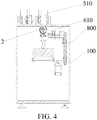
- the smoking machine for an electronic cigarette further comprises an automatic loading and weighing system of a catcher
- the automatic loading and weighing system of a catcher comprises: a temporary feeding storage store 510 and a temporary discharge storage store 520, which are disposed on the housing 100 of the smoking machine for an electronic cigarette and in communication with an inner portion of the housing 100; a transmission mechanism 600, a balance 700, an ejector pin assembly 400, and a discharge transferring mechanism 800, which are disposed inside the housing 100; and a main control circuit board 300 electrically connected to the ejector pin assembly 400, the transmission mechanism 600, the balance 700, the temporary feeding storage store 510, the temporary discharge storage store 520, and the discharge transferring mechanism 800, the temporary feeding storage store 510 receives the catcher 2 disposed from an outer portion of the smoking machine for an electronic cigarette, and the catcher 2 is taken out from the temporary discharge storage store 520; a robotic arm 610 is installed on the transmission mechanism 600, the robotic arm 610 obtains the catcher 2, and the transmission mechanism 600 drives
- the temporary feeding storage store 510 and the temporary discharge storage store 520 may be disposed on a top surface of the housing 100, and the discharge transferring mechanism 800 transfers the catcher 2 to the discharge position of the temporary discharge storage store 520 in a vertical direction.
- the catcher 2 is disposed in the temporary feeding storage store 510 from the outer portion of the smoking machine for an electronic cigarette.
- the main control circuit board 300 controls the transmission mechanism 600 to drive the robotic arm 610 to move from the preparation position to a supporting position close to the bottom of the temporary feeding storage store 510.
- the preparation position is an initial zero position.
- the position is a reference position from which the robotic arm 610 moves to other working positions and is used for calculating a moving distance.
- the main control circuit board 300 controls the catcher 2 in the temporary feeding storage store 510 to fall on the robotic arm 610.
- the robotic arm 610 carries the catcher 2 and returns to the preparation position.
- the main control circuit board 300 controls the ejector pin assembly 400 to push the catcher 2 to the smoking position, and the robotic arm 610 moves together, so that the catcher 2 comes into connection to a smoking end of the electronic cigarette 1 by using the housing sealing member 120, the vapor channel 421 comes into communication with the catcher 2, the smoking apparatus 440 sucks vapor from the electronic cigarette 1 by using the vapor channel 421, and vapor smoke of the electronic cigarette 1 is absorbed by the catcher 2. Based on a specified condition, after a quantity of puffs or cigarettes is smoked, the main control circuit board 300 controls the ejector pin assembly 400 to contract.
- the main control circuit board 300 controls the transmission mechanism 600 to drive the catcher 2 on the robotic arm 610 to spring to the preparation position, and then the catcher 2 moves downward to the weighing position of the balance 700.
- the robotic arm continues to move downward and is slightly separated from the catcher 2, and the balance weighs the catcher 2.
- the main control circuit board 300 controls the transmission mechanism 600 to drive the robotic arm 610 to rise and return to the preparation position.
- the main control circuit board 300 controls the ejector pin assembly 400 to eject the catcher 2 to the smoking position again to perform smoking.
- the smoking and weighing process is repeated based on a specified smoking condition.
- the catcher 2 needs to be taken out when a smoking termination condition is reached, the catcher 2 is transmitted by the discharge transferring mechanism 800 to the discharge position of the temporary discharge storage store 520 by a discharge transferring mechanism.
- a direction at which the central axis of the sealing ventilation hole 121 is located is a smoking experiment direction of the electronic cigarette 1
- the catcher 2 falls on the robotic arm 610 located at a supporting position in a vertical direction, and in a process when the robotic arm 610 drives the catcher 2 to move to the preparation position, the weighing position, and the discharge position, the central axis of the catcher 2 remains in parallel to the central axis of the sealing ventilation hole 121. In this way, when the system consistent with the present invention is used, a ventilation direction of the catcher 2 is always consistent with the smoking experiment direction of the electronic cigarette 1.
- the catcher 2 drops material and cooperates with the robotic arm 610 depending on the gravity, thereby ensuring that the catcher 2 is quickly and stably changed within a smoking interval of two puffs. That is, the electronic cigarette 1 changes the catcher 2 within 27s of the smoking interval of two puffs.
- the catcher 2 is always in an effective control range of the robotic arm 610 inside the smoking machine. Both of the transmission mechanism 600 and the balance 700 are located inside the housing 100. The weighing position and the smoking position are quite close. After smoking is completed, the robotic arm 610 can conveniently move the catcher 2 to the weighing position. After weighing is completed, the robotic arm 610 can move the catcher 2 to the smoking position again. An entire process in which the catcher 2 is moved to the weighing position to be weighed and then returns to the smoking position is controlled by the main control circuit board 300. Therefore, it may also be ensured that all actions are completed within a smoking interval of two puffs. That is, after transferring the catcher 2 from the smoking position to the weighing position to perform weighing within 27s of the smoking interval of two puffs, then returning the catcher 2 to the smoking position.
- the present invention provides an optimized cooperation relationship between rotation of the rotary disc 200 and the automatic loading and weighing system of the catcher 2. While conforming to a related standard rule of a single smoking duration and a smoking volume of the electronic cigarette 1, at least two test procedures may be implemented as follows. Procedure 1: When multiple electronic cigarettes 1 with a same brand and specification are loaded on the rotary disc 200, each of the multiple electronic cigarettes 1 may be continuously and sequentially smoked for one or more puffs. Released aerosol is caught by a filter of the catcher 2. In this process, a smoking interval of two puffs of a single electronic cigarette 1 needs to be longer than 27s according to a rule.
- a smoking process in which the electronic cigarettes 1 are sequentially smoked is set, that is, a next electronic cigarette is smoked after a single electronic cigarette 1 is completely smoked.
- the catcher 2 is automatically changed based on a quantity of puffs of smoking or a set value of a minimum catching amount.
- a continuous test process may complete each puff analysis, entire smoke analysis, and service life detection of multiple electronic cigarettes 1 with different brands and specifications.
- the discharge transferring mechanism 800 comprises an inclined slideway 810 for the catcher 2 to slide and a discharge pushing cylinder 820, a horizontal height of an end of the inclined slideway 810 close to the temporary discharge storage store 520 is less than a horizontal height of an end of the inclined slideway 810 far away from the temporary discharge storage store 520, the discharge pushing cylinder 820 is disposed below the end of the inclined slideway 810 close to the temporary discharge storage store 520, a piston rod of the discharge pushing cylinder 820 is located exactly below the temporary discharge storage store 520, and the piston rod of the discharge pushing cylinder 820 is provided with a supporting portion supporting the catcher 2.
- the inclined slideway 810 is disposed to quickly transfer the catcher 2 to the discharge position. After the robotic arm 610 places the catcher 2 at the end of the slideway 810 far away from the temporary discharge storage store 520, the catcher 2 slides along an inclined direction of the inclined slideway 810 to the end of the inclined slideway 810 close to the temporary discharge storage store 520. In this case, the piston rod of the discharge pushing cylinder 820 is exactly below the catcher 2.
- the main control circuit board 300 controls the piston rod of the discharge pushing cylinder 820 to push the catcher 2 in the vertical direction, so that the catcher 2 can be quickly pushed to the discharge position of the temporary discharge storage store 520.
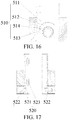
- the temporary feeding storage store 510 is provided with a feeding guiding groove 511 to insert the catcher 2.
- a rotary stopper 512 that can rotate to release the catcher 2 and a feeding identification apparatus 513 that identifies a position of the catcher 2 are disposed in the feeding guiding groove 511. Both the rotary stopper 512 and the feeding identification apparatus 513 are electrically connected to the main control circuit board 300.
- the rotary stopper 512 comprises a stopping portion 514 that can support the catcher 2 and prevent the catcher 2 from moving downward.
- the stopping portion 514 also rotates for 180 degrees, so that the catcher 2 is not restricted by the stopping portion 514 and falls into an inner portion of the housing 100.
- the feeding identification apparatus 513 transmits information of the catcher 2 in the feeding guiding groove 511 to the main control circuit board 300.
- the main control circuit board 300 controls the rotary stopper 512 to rotate by 180 degrees to release the catcher 2, so that the catcher 2 falls on the robotic arm 610 located at the supporting position inside the housing 100.
- the feeding guiding groove 511 limits the position of the catcher 2. Therefore, in the process that the catcher 2 enters the preparation position from the feeding guiding groove 511, the central axis of the catcher 2 is always parallel to a horizontal plane.
- the temporary discharge storage store 520 is provided with a discharge guiding groove 521 to insert the catcher 2.
- An ejecting and pushing stopper 522 that can be turned on when the catcher 2 pushes upward and a discharge identification apparatus 523 that identifies the position of the catcher 2 are disposed in the discharge guiding groove 521. Both the ejecting and pushing stopper 522 and the discharge identification apparatus 523 are electrically connected to the main control circuit board 300.
- the ejecting and pushing stopper 522 comprises two limiting members 524 disposed opposite to each other in the discharge guiding groove 521. Both of the two limiting members 524 are movably connected to the discharge guiding groove 521. The length of an upper portion of the limiting member 524 in a horizontal direction is greater than the length of a lower portion of the limiting member 524 in a horizontal direction.
- the catcher 2 is pushed by the piston rod of the discharge pushing cylinder 820 to the temporary discharge storage store 520.
- the catcher 2 may push the two limiting members 524 to rotate, so that the catcher 2 passes the two limiting members 524.
- the main control circuit board 300 controls the two limiting members 524 to return to an original position and support the catcher 2.
- the piston rod of the discharge pushing cylinder 820 may quickly push the catcher 2 in a vertical direction to pass the two limiting members 524 to reach the discharge position of the discharge guiding groove 521.
- the catcher 2 comprises a catching body 21 and a vapor guiding head 22 disposed on each of two axial end faces of the catching body 21; the robotic arm 610 is formed by two gripers 611 with a V-shaped groove at an end portion; and the V-shaped groove supports the corresponding vapor guiding head 22.
- This structure enables the grippers 611 of the robotic arm 610 to stably support the vapor guiding head 22 and facilitate the robotic arm 610 to drive the catcher 2 to move.
- a weighing end of the balance 700 is provided with an adapter 710 corresponding to the catcher 2.
- the shape of a supporting surface 711 of the adapter 710 corresponds to the shape of a side surface of the catching body 21.
- the supporting surface 711 is arc-shaped. This structure enables the side surface of the catching body 21 of the catcher 2 to be stably placed on the adapter 710, thereby facilitating weighing of the catcher 2.
- the balance 700 is located below the preparation position, so that the robotic arm 610 quickly moves from the smoking position to the weighing position by passing the preparation position.
- the ejector pin assembly 400 comprises an ejector pin cylinder 410 and an adapter sealing member 420.
- the adapter sealing member 420 is connected to a piston rod 41 of the ejector pin cylinder 410, and the vapor channel 421 is disposed on the adapter sealing member 420.
- the adapter sealing member 420 is in sealing connection to a vapor outlet end of the catcher 2, and the vapor channel 421 communicates the catcher 2 with the smoking apparatus 440.
- This structure can quickly push the catcher 2 to the smoking position and enable the catcher 2 to be in sealing connection to the vapor channel 421.
- the adapter sealing member 420 is connected to the smoking apparatus 440 by using a vapor guiding connection rod 430, and the vapor guiding connection rod 430 is in communication with the vapor channel 421.
- the smoking apparatus 440 is in communication with the vapor channel 421 on the adapter sealing member 420 by using the vapor guiding connection rod 430. After smoking is performed, vapor smoke of the electronic cigarette 1 is absorbed by the catcher 2. Both of the smoking apparatus 440 and the ejector pin cylinder 410 are electrically connected to the main control circuit board 300.
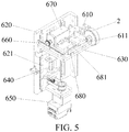
- the transmission mechanism 600 comprises: a vertical guiding plate 620, the vertical guiding plate 620 is provided with a vertical guiding rail 621; a horizontal supporting plate 630, which is installed on the vertical guiding rail 621, and the horizontal supporting plate 630 can vertically move along the vertical guiding rail 621, the horizontal supporting plate 630 is connected to a vertical driving shaft 640, and the vertical driving shaft 640 is connected to a vertical driving motor 650; a horizontal guiding rod 660, which is disposed on the horizontal supporting plate 630; a horizontal guiding plate 680, which is movably connected to the horizontal supporting plate 630, and the horizontal guiding plate 680 can horizontally move on the horizontal supporting plate 630; a horizontal driving motor 670, which is connected to the horizontal guiding plate 680, an output axis of the horizontal driving motor 670 is movable along the horizontal guiding rod 660 in a horizontal direction; and a horizontal guiding rail 681, which is disposed on the horizontal guiding rail 681, which is disposed on the horizontal
- the robotic arm 610 is movably connected to the horizontal guiding rail 681 by using a spring, and the robotic arm 610 is movable along the horizontal guiding rail 681. Both of the vertical driving motor 650 and the horizontal driving motor 670 are electrically connected to the main control circuit board 300.
- the vertical driving motor 650 drives the horizontal supporting plate 630 to move in a vertical direction by using the vertical driving shaft 640.
- the horizontal driving motor 670 drives the horizontal guiding plate 680 to move along the horizontal guiding rod 660.
- the robotic arm 610 can drive the catcher 2 to move along the horizontal guiding rail 681. Since the direction at which the central axis of the horizontal guiding rail 681 is located is perpendicular to the direction in which the horizontal guiding plate 680 horizontally moves on the horizontal supporting plate 630, therefore, the transmission mechanism 600 can enable the robotic arm 610 to drive the catcher 2 to quickly move in three directions perpendicular to each other. In this way, the catcher 2 can quickly move to a required position.
- a usage method of the automatic changing and weighing system of a catcher according to the present embodiment comprises the following steps.
- the catcher 2 is disposed at a feeding position in the temporary feeding storage store 510 from an outer portion of the smoking machine for an electronic cigarette.
- the main control circuit board 300 controls the transmission mechanism 600 to drive the robotic arm 610 to move to the supporting position close to the bottom portion of the temporary feeding storage store 510.
- the main control circuit board 300 controls the rotary stopper 512 of the temporary feeding storage store 510 to rotate by 180 degrees.
- the main control circuit board 300 controls the robotic arm 610 to carry the catcher 2 and move to the preparation position.
- the main control circuit board 300 controls the ejector pin assembly 400 to push the catcher 2 to the smoking position in a horizontal direction.
- the robotic arm 610 moves with the catcher 2, and a spring (not shown in the figures) of the robotic arm 610 connected to the horizontal guiding rail 681 contracts.
- the catcher 2 is connected to the smoking end of the electronic cigarette 1.
- the vapor channel 421 of the ejector pin assembly 400 is in communication with the catcher 2.
- the main control circuit board 300 controls the smoking apparatus 440 to smoke the electronic cigarette 1 by using the vapor channel 421, so that vapor smoke of the electronic cigarette 1 enters the catcher 2 and is absorbed by the catcher 2.
- the main control circuit board 300 controls the ejector pin assembly 400 to contract.
- the spring of the robotic arm 610 connected to the horizontal guiding rail 681 extends, and the robotic arm 610 drives the catcher 2 to return to the preparation position.
- the main control circuit board 300 controls the transmission mechanism 600, so that the transmission mechanism 600 drives the catcher 2 on the robotic arm 610 to move to the weighing position of the balance 700.
- the main control circuit board 300 controls the robotic arm 610 to release the catcher 2, and the balance 700 measures the weight of the catcher 2.
- the main control circuit board 300 controls the robotic arm 610 by using the transmission mechanism 600, so that the catcher 2 moves to an end of the inclined slideway 810 far away from the temporary discharge storage store 520.
- the robotic arm 610 releases the catcher 2, and the catcher 2 slides along the inclined slideway 810 to the supporting portion of the discharge pushing cylinder 820.
- the main control circuit board 300 controls the piston rod of the discharge pushing cylinder 820 to move upward to drive the catcher 2 to push the ejecting and pushing stopper 522 in the temporary discharge storage store 520 to open.
- the discharge identification apparatus 523 transmits detected information indicating that the catcher 2 is located at the discharge position to the main control circuit board 300.
- the main control circuit board 300 controls the two limiting members 524 to return to an initial position and support the catcher 2 below the catcher 2.
- a quantity of smoking puffs of the electronic cigarette 1 is far greater than that of a conventional cigarette, and generally comprises at least 150 or more than 150 puffs.
- a fiberglass Cambridge filter having a diameter of 44 mm well known in this professional technical field is generally used for catching smoke, and a theoretical smoke carrying amount of the fiberglass Cambridge filter is 150 mg.
- a catcher 2 provided with a Cambridge filter needs to be changed after a quantity of smoking puffs. Therefore, the temporary feeding storage store 510 and the temporary discharge storage store 520 of the catcher 2 designed by the present invention are vertically arranged on the top portion of the housing 100.
- An axial direction of the catcher 2 is consistent with a direction of the catcher 2 in a smoking experiment.
- a direction of the vapor inlet of the catcher 2 keeps facing the rotary disc 200.
- the catcher drops material and cooperates with the robotic arm 610 depending on the gravity, thereby ensuring that the catcher 2 is quickly and stably changed within a smoking interval of two puffs.
- the catcher 2 In the continuous measurement process, when a quality change of the catcher 2 in the smoking process needs to be monitored before the catcher 2 is changed, that is, when an amount change occurs on smoke of the electronic cigarette 1, the catcher 2 needs to be weighed at an interval of a quantity of smoking puffs (for example, 1, 2, 3, ... puffs). In this case, the catcher 2 must be removed from a smoking working position originally sealed between the smoking hole channel and a smoking unit of the electronic cigarette 1 and be loaded at the original smoking working position and sealed again after being weighed.
- a quality change of the catcher 2 in the smoking process needs to be monitored before the catcher 2 is changed, that is, when an amount change occurs on smoke of the electronic cigarette 1
- the catcher 2 needs to be weighed at an interval of a quantity of smoking puffs (for example, 1, 2, 3, ... puffs).
- the catcher 2 must be removed from a smoking working position originally sealed between the smoking hole channel and a smoking unit of the electronic cigarette 1 and be loaded at the original smoking working
- a maximum interval of two smoking puffs does not exceed 1 min.
- an interval between two smoking puffs of the electronic cigarette 1 is generally stipulated as 27s.
- the balance 700 disposed inside the smoking machine and the adapter 710 of the balance 700 used to support the catcher 2 are disposed below and quite close to the smoking working position.
- the catcher 2 is pushed to the smoking working position by the ejector pin assembly 400 located at a direction of a vapor outlet of the catcher 2.
- the ejector pin cylinder 410 releases an ejector pin.
- the catcher 2 is supported by the robotic arm 610 and is quickly sent to the adapter 710 supported by the balance 700.
- the catcher 2 is returned by the robotic arm 610, and the ejector pin assembly 400 is tightly pushed again.
- a data collection process of transferring and weighing of the catcher 2 is fully and automatically completed by an instrument, thereby ensuring that all actions are completed within the smoking interval of two puffs.
- a method for determining smoking determination by using a weighting method may be implemented, so as to resolve a determining problem of smoking determination of the electronic cigarette 1:
- a conventional cigarette generates smoke by burning a tobacco segment of the cigarette. Therefore, when the cigarette is burned to a cigarette stub length defined by a standard, a cotton thread in close contact with an outer surface of the cigarette and located at a termination position is burned away to trigger a micro switch, or an infrared sensor disposed at a corresponding position is triggered to terminate smoking.
- the largest value in the following three sets of data is used as the cigarette stub length determining smoking termination: 1. a cigarette without a cigarette filter is 23 mm away from the smoking end; 2.
- the length of a cigarette filter rod is +8 mm; 3. the length of tipping paper is +3 mm.
- the electronic cigarette 1 atomizes tar in the electronic cigarette 1 to generate smoke without a lighting and burning process.
- the method and an apparatus for determining smoking termination of a conventional smoking machine cannot determine whether the electronic cigarette 1 completes smoking.
- a current conventional smoking machine cannot automatically resolve this technical problem.
- the balance 700 weighs the catcher 2 in combination with actions of the robotic arm 610. A weight change of the catcher 2 obtained by the balance 700 is transferred to the main control circuit board 300. In this method, whether smoke is still generated is determined by examining whether the weight increases. This can indirectly determine whether the tobacco tar or electric quantity runs out, thereby determining that smoking of the electronic cigarette 1 terminates.
- a function may further be expanded as follows: the second puffs, the third puffs, or the like of all the electronic cigarettes 1 are sequentially caught on the first filter, the second filter, or the like.
- An advantage of this manner lies in that, for electronic cigarette 1 products with a same brand or specification, when quality detection needs to be performed on an entire batch of the products, quality levels vary between different individuals of a sample test batch. To reduce a detection data error caused by a produce quality difference, a quantity of tested samples must be increased. If the samples are measured one by one by using the conventional smoking machine, that is, the second cigarette is smoked after the first cigarette is completely smoked, a smoking interval of two puffs of each cigarette causes a great amount of time waste.
- the system provided by the present invention can fully utilize a smoking interval of each electronic cigarette 1 to complete smoking of other electronic cigarettes 1, thereby greatly improving the smoking detection efficiency.
- a single electronic cigarette 1 is smoked for one puff every 30 seconds, and 10 minutes are consumed to complete 20 puffs of smoking.
- a total time of 100 minutes is consumed to complete smoking 10 cigarettes one by one.
- each puff of smoking a single electronic cigarette 1 lasts for 3 seconds, and the rotary disc 200 rotates for 1 second.
- a next electronic cigarette 1 is smoked for 3 seconds, and the rotary disc 200 rotates for 1 second again.
- a total time consumed to complete a task for all the 200 puffs of smoking all the 10 cigarettes is 13 minutes and 20 seconds, and a time of 86 minutes and 40 seconds is saved.
- the smoking machine for an electronic cigarette is combined with an automatic material changing system of a catcher.
- a function for which the catcher 2 is successively replenished to the smoking machine for an electronic cigarette and the catcher 2 on the smoking machine for an electronic cigarette that has completed a test is taken out and placed in a discharge store of the automatic material changing system of a catcher can be automatically implemented.
- one or more smoking machines controlled by a bus are combined with the automatic material changing system of a catcher.
- the automatic material changing system of a catcher sends an identification instruction to the feeding identification apparatus 513 on the temporary feeding storage store 510 of each smoking machine for an electronic cigarette and receives a feedback signal indicating whether a catcher 2 exists. If no catcher 2 exists, the catcher 2 is delivered from a feeding rack of the automatic material changing system of a catcher to the temporary feeding storage store of each smoking machine for an electronic cigarette.
- the discharge identification apparatus 523 of the temporary discharge storage store 520 sends the feedback signal to the automatic material changing system of a catcher.
- the system takes out the catcher 2 and sends it to a discharge rack of the system.
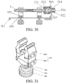
- the smoking machine for an electronic cigarette further comprises an electronic cigarette triggering system.
- the electronic cigarette triggering system comprises a cigarette triggering portion 3 and a triggering control cylinder 4 connected to the cigarette triggering portion 3.
- the cigarette triggering portion 3 is able to come into contact with the electronic cigarette 1 under control of the triggering control cylinder 4, the triggering control cylinder 4 is fixed on a connection block 5, and the connection block 5 is connected to the housing 100 by using a connection structure 6.
- the electronic cigarette triggering system controls the cigarette triggering portion 3 to perform an action by using the triggering control cylinder 4.
- the cigarette triggering portion 3 comes into contact with the electronic cigarette 1; and when the electronic cigarette 1 needs to be powered off, the cigarette triggering portion 3 hangs close to the electronic cigarette 1 and is not in contact with the electronic cigarette 1.
- the electronic cigarette 1 can be clamped by using the cigarette clamp 320 of the cigarette clamping mechanism and a cigarette gripper 330.
- a rear portion of the electronic cigarette 1 is inserted into the housing 100 and is in communication with the smoking apparatus 440 by using a smoking channel.
- the triggering system is installed at a position exactly above the cigarette clamping mechanism. The triggering system controls power on and off of the electronic cigarette 1, and cooperates with a smoking action of the smoking apparatus 440, thereby implementing a function of stimulating cigarette smoking of a consumer.
- the electronic cigarette 1 generally consists of a cigarette cartridge 201 storing tobacco tar and a cigarette rod for installing the cigarette cartridge 201, wherein the cigarette rod is provided with a battery.
- the battery supplies a current to a thermal resistor 2014 in the cigarette cartridge 201, and the thermal resistor 2014 is heated to atomize the tobacco tar.
- the smoking machine is used to detect the electronic cigarette 1, there are two manners to power on the electronic cigarette 1.
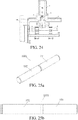
- One manner is to remove an original cigarette rod with the battery of the electronic cigarette 1 and connect the cigarette cartridge 201 to a specially-made electronic cigarette rod 1001 (as shown in Fig. 25a to Fig.
- Another manner is to perform no transformation on the original electronic cigarette 1, but to directly press a power-on button 33 on the cigarette rod of the electronic cigarette 1 in a mechanical manner, thereby powering on the electronic cigarette 1, as shown in Fig. 23 to Fig. 24 .
- the cigarette triggering portion 3 comprises a negative contact terminal 31 and a positive contact terminal 32.
- the negative contact terminal 31 corresponds to a position of the negative electrode 11 of the electronic cigarette 1
- the positive contact terminal 32 corresponds to a position of the positive electrode 12 of the electronic cigarette 1
- the negative contact terminal 31 and the positive contact terminal 32 are connected to a current control apparatus.
- the negative contact terminal 31 and the positive contact terminal 32 are respectively in contact with the negative electrode 11 and the positive electrode 12 under control of the triggering control cylinder 4, thereby powering on the electronic cigarette 1.
- the current control apparatus can adjust parameters such as a current, a voltage, and power, and change the temperature of the thermal resistor 2014 in the cigarette cartridge 201, thereby adjusting an atomization degree of tobacco tar.
- an external direct current has characteristics such as supplying power by using a regulated voltage and a regulated current.
- a one-time charging electric quantity of a rechargeable battery of the electronic cigarette is usually insufficient to completely consume tobacco tar in the cigarette cartridge 201.
- the examination cannot be completed in one time by using the rechargeable battery.
- a sample needs to be removed to recharge the battery, which will inevitably cause an experimental process to be interrupted, resulting in an experimental error.
- a steady direct current supplied by the current control apparatus of the smoking machine is used.
- Power is supplied to the cigarette cartridge 201 in a manner in which the negative contact terminal 31 and the positive contact terminal 32 are respectively in contact with the negative electrode 11 and the positive electrode 12 of the electronic cigarette 1.
- a measurement process is continuous and stable, and measurement data is accurate and effective.
- parameters such as a voltage, a current, and power can be adjusted and set by using the current control apparatus, the temperature of a heating wire can be changed, atomization efficiency of tobacco tar under different electric quantities can be examined, and a technical basis is provided for research and development of a product.
- the present invention specially designs an electronic cigarette rod 1001 applicable to the electronic cigarette triggering system.
- an electronic cigarette 1 formed by the electronic cigarette rod 1001 provided with the cigarette cartridge 201 is applicable to the direct-current power-on mode of the electronic cigarette triggering system.
- a structure of the electronic cigarette rod 1001 is shown in Fig. 25a to Fig. 25c .
- the electronic cigarette rod 1001 comprises a positive electrode pipe 101 and a negative electrode pipe 102 sleeved over the positive electrode pipe 101.
- An end of the positive electrode pipe 101 far away from the cigarette cartridge 201 is in contact with the positive contact terminal 32, and an end of the positive electrode pipe 101 close to the cigarette cartridge 201 passes through the inner portion of the negative electrode pipe 102 and is in contact with a positive electrode of the cigarette cartridge 201.
- An outer surface of the negative electrode pipe 102 is in contact with the negative contact terminal 31, and an end of the negative electrode pipe 102 close to the cigarette cartridge 201 is in contact with a negative electrode of the cigarette cartridge 201.
- the negative electrode pipe 102 is isolated from the positive electrode pipe 101 by using multiple insulation rings.
- the negative electrode pipe 102 and the positive electrode pipe 101 are respectively connected to the negative electrode and the positive electrode of the cigarette cartridge 201, and are further connected to the negative contact terminal 31 and the positive contact terminal 32.
- the negative contact terminal 31 and the positive contact terminal 32 are respectively conductive to the negative electrode and the positive electrode of the cigarette cartridge 201.
- a current from the electronic cigarette triggering system causes the thermal resistor 2014 of the cigarette cartridge 201 to be heated, so that tobacco tar is atomized.
- a function of stimulating cigarette smoking of a consumer is implemented.
- the electronic cigarette rod 1001 may be in threaded connection to the cigarette cartridge 201 or an adapter 105.
- a specific structure is that a conductive threaded head 103 is fixed in the end of the negative electrode pipe 102 close to the cigarette cartridge 201, an outer surface of the threaded head 103 cooperates with an inner surface of the negative electrode pipe 102, and an inner surface of the threaded head 103 is provided with a connection thread.
- the cigarette cartridge 201 or the adapter 105 is provided with a thread corresponding to the thread of the inner surface of the threaded head 103, and the cigarette cartridge 201 or the adapter 105 is in threaded connection to the threaded head 103.
- the inner surface of the threaded head 103 is further provided with a limiting protruding ring 1031 extending radially inward.
- a first insulation ring 104 is filled between the limiting protruding ring 1031 and an outer surface of the positive electrode pipe 101.
- the positive electrode pipe 101 is fixed at a central position of the negative electrode pipe 102 by using the limiting protruding ring 1031 and the first insulation ring 104.
- the limiting protruding ring 1031 and the first insulation ring 104 ensure insulativity between the positive electrode pipe 101 and the negative electrode pipe 102.
- a second insulation ring 106 is further disposed between an end of the negative electrode pipe 102 far away from the cigarette cartridge 201 and the positive electrode pipe 101.
- the second insulation ring 106 also ensures insulativity between the positive electrode pipe 101 and the negative electrode pipe 102.
- the positive electrode pipe 101 comprises a positive electrode pipe rear segment 1011 and a positive electrode pipe front segment 1012.
- the positive electrode pipe front segment 1012 is inserted into the positive electrode pipe rear segment 1011.
- An outer surface of the positive electrode pipe rear segment 1011 is in contact with the positive contact terminal 32, and the positive electrode pipe front segment 1012 is in contact with the positive electrode of the cigarette cartridge 201.
- the middle of the positive electrode pipe 101 is provided with a smoking channel 97 in communication with a smoking channel 111 of the cigarette cartridge 201.
- two ends of the smoking channel 97 of the positive electrode pipe 101 are respectively in communication with the smoking channel 111 of the cigarette cartridge 1 in external air, and the smoking channel 111 of the cigarette cartridge 1 is in communication with the smoking apparatus 440 located inside the smoking machine.
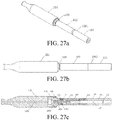
- the electronic cigarette rod 1001 may be directly connected to the cigarette cartridge 1 (as shown in Fig. 26a to Fig. 26c ), or may be connected to the cigarette cartridge 1 by using the adapter 105 (as shown in Fig. 27a to Fig. 27c ).
- the negative conductive pipe 2018 is provided with a positioning protruding ring 2019 radially protruding inward.
- a third insulation ring 2020 is disposed between the positioning protruding ring 2019 and the positive conductive pipe 2017.
- the two ends of the smoking channel 97 of the positive electrode pipe 101 are respectively in communication with the smoking channel 111 of the cigarette cartridge 1 in external air, and the smoking channel 111 of the cigarette cartridge 1 extends into the atomization cavity 2011 of the cigarette cartridge 1.
- the atomization cavity 2011 is in communication with the smoking apparatus 440 located inside the smoking machine by using a through hole on the electronic cigarette cap 2013.
- the electronic cigarette rod 1001 is connected to the cigarette cartridge 201 by using the adapter 105.
- the electronic cigarette rod 1001 further comprises the adapter 105.
- the adapter 105 comprises a negative connection pipe 1051 and a positive connection pipe 1052 located inside the negative connection pipe 1051. Two ends of the negative connection pipe 1051 are respectively in contact with the negative electrode pipe 102 and the negative electrode of the cigarette cartridge 201. Two ends of the positive connection pipe 1052 are respectively in contact with the positive electrode pipe 101 and the positive electrode of the cigarette cartridge 201.
- a fourth insulation ring 953 is disposed between the negative connection pipe 1051 and the positive connection pipe 1052.
- the middle of the adapter 105 is further provided with a smoking channel 954 passing through the positive connection pipe 1052.
- the smoking channel 97 of the electronic cigarette rod 1001 is in communication with the smoking channel 111 of the cigarette cartridge 201 by using the smoking channel 954.
- a peripheral surface of the negative connection pipe 1051 is provided with a thread.
- One end of the negative connection pipe 1051 is in threaded connection to the threaded head 103 of the electronic cigarette rod 1001, and the other end is in threaded connection to the cigarette cartridge 201.
- the diameter of the peripheral surface of the negative connection pipe 1051 cooperating with the threaded head 103 and the cigarette cartridge 201 depends on the diameter of a threaded cooperating surface of the threaded head 103 and the cigarette cartridge 201.
- the cigarette cartridges 201 with different diameters may be connected to the electronic cigarette rod 1001 by using the adapter 105, thereby expanding an applicable range of the electronic cigarette rod 1001.
- the cigarette triggering portion 3 comprises a cigarette pressing terminal 13, and the cigarette pressing terminal 13 corresponds to a position of the power-on button 33 of the electronic cigarette 1.
- the triggering control cylinder 4 controls the cigarette pressing terminal 13 to press the power-on button 33 of the electronic cigarette 1, thereby powering on the electronic cigarette 1.
- a pressing force of the cigarette pressing terminal 13 may be adjusted.
- a reducing valve is disposed on the triggering control cylinder 4. Air source pressure of the triggering control cylinder 4 is adjustable by adjusting the reducing valve, thereby controlling the pressure of the cigarette pressing terminal 13, and the cigarette pressing terminal 13 is able to be adaptive to pressing strength required by electronic cigarettes 1 with different versions.
- a pre-triggering time may be set pinpointing to a millisecond level.
- time needs to be controlled quite accurately.
- a pressing action and an electronic cigarette triggering moment itself will lead to a triggering delay.
- an advance amount of a given triggering time may be implemented, thereby eliminating a delay problem of the triggering time.
- the foregoing cigarette triggering portion 3 is fixed on an integrated block 7.
- the integrated block 7 is fixedly connected to the piston rod 41 of the triggering control cylinder 4.
- the integrated block 7 and the cigarette triggering portion 3 are driven to move by triggering scalability of the piston rod 41 of the triggering control cylinder 4, so that a position of the cigarette triggering portion 3 is adjusted and contact between the cigarette triggering portion 3 and the electronic cigarette 1 is controlled.
- an axis of the piston rod 41 of the triggering control cylinder 4 is preferably disposed perpendicular to an axis of the electronic cigarette 1.
- the negative contact terminal 31 and the positive contact terminal 32 of the cigarette triggering portion 3 used for direct current power-on and the cigarette pressing terminal 13 used for pressing power-on may be jointly integrated and installed on one integrated block 7.
- the cigarette triggering portion 3 has two triggering manners and the cigarette triggering portion 3 may flexibly select direct current power-on or pressing power-on.
- a preferable arranging manner is as follows: the cigarette pressing terminal 13 is located between the negative contact terminal 31 and the positive contact terminal 32, and the three terminals are sequentially arranged in a direction parallel to the axis of the electronic cigarette 1.
- the connection structure 6 comprises a fixed rod 61 connected to the smoking machine.
- the fixed rod 61 is provided with a guiding rail 62, and a connection block 5 slides on the guiding rail 62.
- a position of the cigarette triggering portion 3 may be flexibly adjusted when the connection block 5 slides on the guiding rail 62, so that the cigarette triggering portion 3 may be applicable to electronic cigarettes 1 with different specifications.
- an axis of the guiding rail 62 is parallel to the axis of the electronic cigarette 1.
- the connection block 5 is further provided with a lock bolt. After the connection block 5 slides in position, the lock bolt is pressed on the guiding rail 62, so that the connection block 5 is fixed relative to the guiding rail 62.
- a position of the cigarette triggering portion 3 in a direction parallel to the axis of the electronic cigarette 1 is adjusted through the sliding of the connection block 5 on the guiding rail 62; and a position of the cigarette triggering portion 3 in a direction perpendicular to the axis of the electronic cigarette 1 is adjusted through stretching of the piston rod 41 of the triggering control cylinder 4.
- the cigarette triggering portion 3 may be adjusted to different positions.
- the triggering system can be applicable to electronic cigarettes 1 with different specifications.
- the clamping mechanism body 310 comprises a horizontal base plate 311 and a vertical supporting plate 314, an upper surface of the horizontal base plate 311 is provided with a guiding groove 312, the guiding groove 312 is disposed in a direction of the length of the horizontal base plate 311; and a bottom portion of the vertical supporting plate 314 is connected to a rear end of the horizontal base plate 311, and the vertical supporting plate 314 is provided with a base through hole 315 penetrating in a horizontal direction; the other end of the cigarette clamp 320 is a disc body connection end 324, and the disc body connection end 324 passes through the base through hole 315 of the vertical supporting plate 314; and the cigarette clamping mechanism further comprises a cigarette gripper 330, and the cigarette gripper 330 comprises a gripper base plate 331 and two side surface clamping portions 334 disposed opposite to each other provided on the gripper base plate 331, the gripper base plate 331 is installed on the guiding groove 312 of the
- the smoking end of a cigarette is inserted into the cigarette clamping end 321 of the cigarette clamp 320.
- the two side surface clamping portions 334 are symmetrically disposed by using a vertical plane of a central axis of the axial through hole 322 as a central axial plane, so that after the two side surface clamping portions 334 disposed opposite to each other clamp side surfaces of the cigarette, a central axis of the cigarette can accurately align with the axial through hole 322 on the cigarette clamp 320, keeping the cigarette airtight all the time after being inserted into the cigarette clamp 320 and keeping a position of the cigarette to be stable.
- the gripper base plate 331 is movable in the direction of the length of the guiding groove 312, so that a position at which the two side surface clamping portions 334 clamp the cigarette can change based on a structure of the cigarette. This enables the cigarette clamping mechanism consistent with the present invention to clamp cigarettes of various types.
- the rotary disc 200 consistent with the present invention is perpendicular to a horizontal plane, and the electronic cigarette 1 circumferentially rotates along with the rotary disc 200 in a smoking experiment process, so that tobacco tar in a cigarette cartridge flows and fully immerses the oil guiding cotton, thus ensuring sufficient and steady supply of the tobacco tar to an atomizer, and guaranteeing atomization efficiency, atomization amount, and the stability and accuracy of experiment data.
- the cigarette clamping mechanism cooperates with a rotation direction of the rotary disc 200 to stably clamp the electronic cigarette 1.
- the automatic loading and weighing system of a catcher cooperates with an operation direction of the rotary disc 200 to control the catcher 2 to move to a required position.
- a ventilation direction of the catcher 2 is always consistent with a smoking experiment direction of the electronic cigarette 1. This can ensure that the catcher 2 is quickly and stably changed during a smoking interval of two puffs, and can also ensure that the catcher 2 returns to the smoking position after a weighing action is completed during the smoking interval of two puffs.
- the electronic cigarette triggering system consistent with the present invention implements automatic control of triggering of the electronic cigarette 1 and resolves a problem that an existing smoking machine does not have a manually triggered electronic cigarette triggering system and external power supply.
- the two side surface clamping portions 334 are symmetrically disposed by using a vertical plane of a central axis of the axial through hole 322 as a central axial plane, so that after the two side surface clamping portions 334 clamp side surfaces of the cigarette, a central axis of the cigarette can accurately align with the axial through hole 322 on the cigarette clamp 320, keeping the cigarette airtight all the time after being inserted into the cigarette clamp 320 and keeping a position of the cigarette to be stable.
- the gripper base plate 331 is movable in a direction of the length of the guiding groove 312, so that a position at which the two side surface clamping portions 334 clamp the cigarette can change based on a structure of the cigarette. This enables the cigarette clamping mechanism consistent with the present invention to clamp cigarettes of various types.
- a bottom surface of the guiding groove 312 is provided with a guiding through hole 313.
- the gripper base plate 331 is provided with a fastening hole 332.
- a fastening member 338 sequentially passes through the guiding through hole 313 and the fastening hole 332 so as to connect the horizontal base plate 311 and the gripper base plate 331.
- the fastening hole 332 is a threaded hole and the fastening member 338 is a screw.
- This structure enables the gripper base plate 331 to be fixedly connected to the horizontal base plate 311 after the gripper base plate 331 moves to a required position in a direction of the length of the guiding groove 312, so that a position of the gripper base plate 331 can be fixed.
- a bottom surface of the gripper base plate 331 is provided with a protruding portion 333.
- the protruding portion 333 is inserted into the guiding groove 312 and is in contact with the bottom surface of the guiding groove 312.
- the fastening hole 332 passes through the protruding portion 333.
- the gripper base plate 331 and the protruding portion 333 are integrally formed to form a T-shaped structure.
- the protruding portion 333 is in contact with the bottom surface of the guiding groove 312, and the gripper base plate 331 is in contact with an upper surface of the horizontal base plate 311.
- each side surface clamping portion 334 comprises a spring plate 335 disposed on the gripper base plate 331 and a guiding member 336 disposed in an inner side of the spring plate 335.
- An inner side surface of the guiding member 336 is provided with a V-shaped groove. V-shaped grooves of two guiding members 336 on a same gripper base plate 331 are disposed opposite to each other.
- the spring plate 335 is elastic. When the two spring plates 335 are pulled open, a cigarette can be conveniently placed between the two spring plates 335, a resilience of the two spring plates 335 can be used to clamp the cigarette, and the two spring plates 335 can clamp cigarettes with different sizes.
- a connected line between central points of groove bottoms of the V-shaped grooves of the two guiding members 336 is perpendicular to the central axis of the axial through hole 322 on the cigarette clamp 320. This structure enables a central axis of a cigarette clamped by the two V-shaped grooves to accurately align with the central axis of the axial through hole 322.
- An inner wall of the cigarette clamping end 321 of the cigarette clamp 320 is provided with a labyrinth ring 323. This structure facilitates the smoking end of the cigarette to be connected to the cigarette clamping end 321 of the cigarette clamp 320.
- At least two cigarette grippers 330 There are at least two cigarette grippers 330. At least two cigarette grippers 330 can clamp a cigarette at multiple clamping positions. This ensures a stable position for each cigarette.
- an outer diameter of the cigarette clamping end 321 of the cigarette clamp 320 is greater than a diameter of the base through hole 315 of the vertical supporting plate 314.
- the present invention effectively overcomes various disadvantages in the prior art and has high industrial usage value.
Landscapes
- Health & Medical Sciences (AREA)
- Life Sciences & Earth Sciences (AREA)
- General Physics & Mathematics (AREA)
- Physics & Mathematics (AREA)
- General Health & Medical Sciences (AREA)
- Chemical & Material Sciences (AREA)
- Pathology (AREA)
- Immunology (AREA)
- Biochemistry (AREA)
- Analytical Chemistry (AREA)
- Engineering & Computer Science (AREA)
- Biomedical Technology (AREA)
- Molecular Biology (AREA)
- Anesthesiology (AREA)
- Pulmonology (AREA)
- Bioinformatics & Cheminformatics (AREA)
- Veterinary Medicine (AREA)
- Public Health (AREA)
- Heart & Thoracic Surgery (AREA)
- Animal Behavior & Ethology (AREA)
- Hematology (AREA)
- Manufacturing Of Cigar And Cigarette Tobacco (AREA)
- Sampling And Sample Adjustment (AREA)
Abstract
Description
- The present invention relates to the technical field of electronic cigarettes, and in particular to a smoking machine for an electronic cigarette.
- An electronic cigarette is a new type of product. Different from a cigarette manufactured by using conventional tobacco and smoked through lighting, currently, main electronic cigarette products atomize tobacco tar through electrical heating and turns aerosol agent, odorous constituents, and nicotine in the tobacco tar into an aerosol state, so as to simulate an effect of cigarette smoke for inhaling by a consumer and the consumer will obtain a satisfactory feeling. Because the electronic cigarette provides a consumption experience similar to that of a cigarette, and has extremely few harmful ingredients therein relative to the conventional tobacco, the electronic cigarette has become a representative developing direction of a new type of tobacco product. China is a cradle and a main manufacturing site of the electronic cigarette. Globally, 90% or more than 90% of electronic cigarettes are produced in China. However, research and supervision for the electronic cigarette is still in infancy both home and abroad. Currently, a smoking method applied to electronic cigarette detection work and a related technical standard are also in a research and stipulation stage. With continuous development of the product scale, continuous in-depth research, and continuous increased technical requirements, a dedicated instrument device suitable for electronic cigarette detection, especially a smoking machine with perfect functions and stable performance required for product research and development and quality control is more urgently needed.
- As shown in
Fig. 1 , an existing rotary-disc smoking machine has arotary disc 81 that horizontally rotates. Therotary disc 81 is perpendicular to a horizontal plane with arotary axis 84 as a central line. Several cigarette clamps are evenly arranged on therotary disc 81 along a periphery of therotary disc 81. During smoking, a cigarette is inserted into acigarette clamp 82, and therotary disc 81 horizontally rotates. An axial central line of the cigarette is perpendicular to therotary axis 84. During smoking, smoke is transmitted to a catcher in the rotary-disc smoking machine from a smoketransmission bending pipe 83 of 90 degrees behind thecigarette clamp 82. - As shown in
Fig. 2 , on an existing linear smoking machine, severalsmoking hole channels 85 are linearly arranged. Eachsmoking hole channel 85 is provided with a cigarette clamp correspondingly. Eachsmoking hole channel 85 is connected to an independent smoking unit. When several cigarettes are lit together, the cigarettes are synchronously smoked based on a smoking capacity defined by a standard. - The working principle of the existing electronic cigarette is as follows: A control circuit is triggered by a switch manually or through pneumatic pressure and supplies power to a heating wire. A current enables the heating wire to generate a high temperature. A fiberglass oil guiding rope twisting inside the heating wire is affected by the high temperature and generates a wick effect. Tobacco tar is continuously transmitted to a high temperature end along the fiberglass oil guiding rope. When reaching a twisted position of the heating wire, the tobacco tar is instantly heated and vaporized into smoke. A smoker smokes by using a cigarette holder. Airflow enters from a vapor inlet hole, and vapor smoke generated in an atomization cavity is inhaled from the cigarette holder to obtain a feeling similar to cigarette smoking. Because of a gravity relationship, the tobacco tar can flow in a storage cavity but is unevenly distributed. The electronic cigarette does not move on the existing linear smoking machine, but on the existing rotary-disc smoking machine, the electronic cigarette horizontally rotates. The tobacco tar is always deposited at a lower portion of a liquid storage cavity due to the gravity. The tobacco tar is consumed in a continuous test process. When a remaining amount of the tobacco tar cannot ensure that the upper fiberglass oil guiding rope is always immersed and replenished by the tobacco tar, a great change may occur on atomization amount due to insufficient tobacco tar replenishment amount, and a smoke amount is decreased. For different electronic cigarette sample rooms or individual rooms having same design, different atomization results may be generated in an actual detection process. Compared with some electronic cigarette oil storage cavities having different types of design, for example, an electronic cigarette whose oil guiding cotton is wrapped in oil storage cotton, the tobacco tar replenishment amount and timeliness of replenishment cause a difference due to different detection devices or methods. Finally, a deviation and a larger error of a detection result are caused.
- Both of mechanisms of the two conventional smoking machines are not provided with a manually or linkage controlled pressing part, and do not have a function for testing a manually triggered electronic cigarette.
- For automatic determination of smoking termination of a conventional cigarette, that is, position determination when the cigarette is completely burned, the two smoking machines use a method in which a cotton thread in close contact with the cigarette is burned away or an infrared sensing identification manner. An electronic cigarette has no lighting or extinguishment process, the smoking machine cannot directly judge online whether tobacco tar or a battery quantity of the electronic cigarette runs out, that is, a service life of the electronic cigarette.
- A cigarette cartridge portion of an electronic cigarette has a large tobacco tar storage capacity. A total aerosol releasing quantity after atomization far exceeds a catching capability of a single fiberglass Cambridge filter. Therefore, when quality stability performance of the electronic cigarette during continuous use is continuously tested, a filter catcher must be changed after several puffs are smoked. In addition, in consideration of a real-time monitored changing condition of the aerosol releasing quantity, multiple catcher weighing actions may be added during catching of a single filter. In use of a conventional smoking machine, an experiment process needs to be manually interrupted to change a catcher provided with a Cambridge filter. In this way, labor costs are inevitably increased, working efficiency is reduced, and a possibility of a deviation or error of an experiment result is increased to a great extent.
- In view of the shortcomings in the prior art described above, a smoking machine for an electronic cigarette provided in the present invention resolves the following technical problems:
- 1. During test, flowing of tobacco tar is automatically implemented by circumferentially rotating an electronic cigarette, so that tobacco tar fully immerses fiberglass tar guiding rope, thereby ensuring a tar guiding effect and atomization amount stability.
- 2. Through an automatic loading and weighing system of a catcher disposed on the smoking machine for an electronic cigarette. In a smoking gap of the electronic cigarette, a catcher is automatically weighed, and whether smoke is still released is judged based on a variation between two weighing values, that is, a service life of the electronic cigarette is judged. At the same time, the stability of the quality of the electronic cigarette is judged based on several recorded weighing results.
- 3. Through an automatic loading and weighing system of a catcher disposed on the smoking machine for an electronic cigarette, a new catcher is automatically exchanged in a smoking gap of the electronic cigarette according to a set quantity of smoking puffs or cigarettes. While a test process is not interrupted, a problem that a releasing amount of electronic cigarette smoke exceeds a bearing capability of a filter of a single catcher is resolved.
- 4. Through an electronic cigarette triggering system and an electronic cigarette rod used in combination, which are carried in the smoking machine for an electronic cigarette, online smoking synchronization triggering can be implemented for a manually triggered electronic cigarette, and external power supply may be performed on a cigarette cartridge of a split-type electronic cigarette by using the electronic cigarette rod used in combination. This resolves a condition in which a battery of the split-type electronic cigarette is in lack of electricity or unstably supplies power, and ensures continuity of the test process.
- The present invention provides a smoking machine for an electronic cigarette, comprising: a housing; a rotary disc installed on the housing, the rotary disc rotates relative to the housing with a central axis of the rotary disc as a center; at least one disc-body smoking through hole is provided on an end face of the rotary disc; a housing sealing member is disposed on the housing, a sealing ventilation hole penetrating into an inner portion of the housing is provided in the housing sealing member, and when the sealing ventilation hole is in communication with one end of a catcher, the other end of the catcher is in communication with a smoking apparatus; the central axis of the rotary disc is parallel to a horizontal plane; and at least one cigarette clamping mechanism, comprising a clamping mechanism body and a cigarette clamp disposed on the clamping mechanism body, wherein the cigarette clamp is installed on the disc-body smoking through hole of the rotary disc; one end of the cigarette clamp is a cigarette clamping end for inserting therein an electronic cigarette in a horizontal direction, the cigarette clamp is provided with an axial through hole penetrating in a horizontal direction for smoke to pass through, and the rotary disc is able to rotate to a position to make the axial through hole in communication with the sealing ventilation hole of the housing sealing member.
- The central axis of the rotary disc consistent with the present invention is parallel to the horizontal plane, that is, a central line around which the rotary disc rotates is parallel to the horizontal plane. The rotary disc is provided with at least one disc-body smoking through hole. The disc-body smoking through hole passes through two end faces of the rotary disc. The disc-body smoking through hole is provided with the cigarette clamping mechanism for clamping the electronic cigarette. The axial through hole of the cigarette clamp on the cigarette clamping mechanism is disposed in the horizontal direction. When the axial through hole of the cigarette clamp is driven by the rotary disc to rotate to a position aligning with the sealing ventilation hole, the axial through hole comes into communication with the sealing ventilation hole. When the rotary disc rotates for a circle, since the electronic cigarette is clamped and fixed on the cigarette clamping mechanism, and the electronic cigarette rolls for a circle relative to the housing with the central axis of the rotary disc as a center. Tobacco tar stored inside the electronic cigarette flows along an inner wall of a tobacco tar storage cavity for a circle, automatically fully immersing a fiberglass tar guiding rope during flowing. This effectively resolves a smoke output stability problem generated by tobacco tar deposition of a conventional smoking machine, so that a test result is more accurate and close to a real smoking behavior.
- At the same time, the catcher is pushed to move in the horizontal direction to a smoking position, so that the catcher is in communication with the sealing ventilation hole of the housing sealing member. That is, during smoking, smoke enters the catcher in the horizontal direction from the axial through hole of the cigarette clamp and the sealing ventilation hole of the housing sealing member. The catcher and the electronic cigarette can be coaxially arranged, which remarkably reduces bumping condensation deposition of aerosol in a bending pipe of a conventional smoking machine, reduces transmission losses, is beneficial to correctness of smoke detection analysis, and resolves a technical problem that is difficult to solve for a conventional smoking machine during smoking of the electronic cigarette.
- Preferably, when two or more disc-body smoking through holes exist, the two or more disc-body smoking through holes are evenly arranged on the rotary disc, and distances between central axes of the disc-body smoking through holes and the central axis of the rotary disc are the same. When the rotary disc rotates, this structure enables the axial through hole of the cigarette clamp to sequentially come into communication with the sealing ventilation hole of the housing sealing member.
- Further, the housing sealing member is disposed on an upper portion of a side surface of the housing, and a central axis of the sealing ventilation hole and the central axis of the rotary disc both pass through a vertical plane perpendicular to the horizontal plane. The catcher is generally disposed inside from a top portion of the housing. To facilitate the catcher to quickly move to the smoking position corresponding to the sealing ventilation hole of the housing sealing member, the housing sealing member is disposed on an upper portion of the housing, and the central axis of the sealing ventilation hole and the central axis of the rotary disc pass through the vertical plane. This structure enables the axial through hole to move to a position close to the top portion of the housing and come into communication with the sealing ventilation hole of the housing sealing member.
- Preferably, an end face of the housing sealing member is in contact with the end face of the rotary disc, and the end face of the rotary disc in contact with the housing sealing member is a plane. This facilitates the end face of the rotary disc and the sealing ventilation hole of the housing sealing member to be sealed during rotation of the rotary disc.
- Preferably, the smoking machine for an electronic cigarette further comprises an automatic loading and weighing system of a catcher, and the automatic loading and weighing system of a catcher comprises: a temporary feeding storage store and a temporary discharge storage store, which are disposed on the housing of the smoking machine for an electronic cigarette and in communication with an inner portion of the housing; a transmission mechanism, a balance, an ejector pin assembly, and a discharge transferring mechanism, which are disposed inside the housing; and a main control circuit board electrically connected to the ejector pin assembly, the transmission mechanism, the temporary feeding storage store, the temporary discharge storage store, and the discharge transferring mechanism; the temporary feeding storage store receives the catcher disposed from an outer portion of the smoking machine for an electronic cigarette, and the catcher is taken out from the temporary discharge storage store; a robotic arm is installed on the transmission mechanism, the robotic arm obtains the catcher, the transmission mechanism drives the robotic arm to move, so that the catcher reaches a preparation position and a weighing position, and during moving of the catcher, a central axis of the catcher remains in parallel to a central axis of the sealing ventilation hole; the balance weighs the catcher reaching the weighing position; the ejector pin assembly pushes the catcher to horizontally move to a smoking position, and the ejector pin assembly is provided with a vapor channel for sucking vapor; and the discharge transferring mechanism transfers the catcher to the temporary discharge storage store.
- The catcher is disposed inside the temporary feeding storage store from the outer portion of the smoking machine for an electronic cigarette. When the electronic cigarette needs to be smoked, the main control circuit board controls the transmission mechanism to drive the robotic arm to move from the preparation position to a supporting position close to the bottom of the temporary feeding storage store. The preparation position is an initial zero position. The position is a reference position from which the robotic arm moves to other working positions and is used for calculating a moving distance. The main control circuit board controls the catcher in the temporary feeding storage store to fall on the robotic arm. The robotic arm carries the catcher and returns to the preparation position. Subsequently, the main control circuit board controls the ejector pin assembly to push the catcher to the smoking position, so that the catcher comes into connection to a smoking end of the electronic cigarette, and the vapor channel comes into communication with the catcher. The smoking apparatus sucks vapor from the electronic cigarette by using the vapor channel, and vapor smoke of the electronic cigarette is absorbed by the catcher. After smoking is completed, the main control circuit board controls the ejector pin assembly to contract. The main control circuit board controls the transmission mechanism to drive the catcher on the robotic arm to move to the weighing position of the balance and the balance weighs the catcher. When the catcher needs to be taken out, the catcher is transmitted to a discharge position of the temporary discharge storage store by a discharge transferring mechanism.
- A ventilation direction of the catcher is always consistent with a smoking experiment direction of the electronic cigarette. The catcher drops material and cooperates with the robotic arm depending on the gravity, thereby ensuring that the catcher is quickly and stably changed within a smoking interval of two puffs. The catcher is always controlled by the robotic arm inside the smoking machine. The smoking position is quite close to the weighing position, so that the robotic arm can quickly move to a required position under control of the main control circuit board. This ensures that the catcher returns to the smoking position after a weighing action is completed within the smoking interval of two puffs.
- Further, the discharge transferring mechanism comprises an inclined slideway for the catcher to slide and a discharge pushing cylinder. A horizontal height of an end of the inclined slideway close to the temporary discharge storage store is less than a horizontal height of an end of the inclined slideway far away from the temporary discharge storage store, the discharge pushing cylinder is disposed below the end of the inclined slideway close to the temporary discharge storage store, and a piston rod of the discharge pushing cylinder is located exactly below the temporary discharge storage store.
- In order to quickly transfer the catcher to the discharge position, the discharge transferring mechanism is provided with the inclined slideway. After the robotic arm places the catcher at the end of the slideway far away from the temporary discharge storage store, the catcher slides along an inclined direction of the inclined slideway to the end of the inclined slideway close to the temporary discharge storage store. In this case, the piston rod of the discharge pushing cylinder is exactly below the catcher. The main control circuit board controls the piston rod of the discharge pushing cylinder to push the catcher in a vertical direction, so that the catcher can be quickly pushed to the discharge position of the temporary discharge storage store.
- Further, the catcher comprises a catching body and a vapor guiding head disposed on each of two axial end faces of the catching body, the robotic arm is formed by two grippers with a V-shaped groove at an end portion, and the V-shaped groove supports the corresponding vapor guiding head. This structure enables the grippers of the robotic arm to stably support the vapor guiding head and facilitates the robotic arm to drive the catcher to move.
- Further, the ejector pin assembly comprises an ejector pin cylinder and an adapter sealing member. The adapter sealing member is connected to a piston rod of the ejector pin cylinder, the vapor channel is disposed on the adapter sealing member, and when the catcher is located at the smoking position, the adapter sealing member is in sealing connection to a vapor outlet end of the catcher, and the vapor channel communicates the catcher with the smoking apparatus. This structure can quickly push the catcher to the smoking position and enable the catcher to be in sealing connection to the vapor channel.
- Preferably, the smoking machine for an electronic cigarette further comprises an electronic cigarette triggering system, the electronic cigarette triggering system comprises a cigarette triggering portion and a triggering control cylinder connected to the cigarette triggering portion, the cigarette triggering portion is able to come into contact with the electronic cigarette under control of the triggering control cylinder, the triggering control cylinder is fixed on a connection block, and the connection block is connected to the housing by using a connection structure. A dedicated electronic cigarette triggering system is installed on the housing, so that automatic control of electronic cigarette triggering is implemented, and a problem that an existing smoking machine does not have a manually triggered electronic cigarette triggering system and external power supply is resolved.
- Further, the cigarette triggering portion comprises a negative contact terminal and a positive contact terminal, the negative contact terminal corresponds to a position of a negative electrode of the electronic cigarette, the positive contact terminal corresponds to a position of a positive electrode of the electronic cigarette, and the negative contact terminal and the positive contact terminal are connected to a current control apparatus. In this technical solution, a steady direct current supplied by the current control apparatus of the smoking machine is used. Power is supplied to the cigarette cartridge connected to the electronic cigarette rod in a manner in which the positive contact terminal and the negative contact terminal are respectively in contact with the positive electrode and negative electrode of the electronic cigarette. This solution makes a measurement process continuous and stable, and measurement data is accurate and effective. In addition, in the foregoing technical solution, parameters such as a voltage, a current, and power can be adjusted and set by using the current control apparatus, the temperature of a heating wire can be changed, atomization efficiency of tobacco tar under different electric quantities can be examined, and a technical basis is provided for research and development of a product.
- Further, the cigarette triggering portion comprises a cigarette pressing terminal, and the cigarette pressing terminal corresponds to a position of a power-on button of the electronic cigarette. The foregoing solution is used to trigger the electronic cigarette, and a pre-triggering time may be set pinpointing to a millisecond level, an advance amount of a specified triggering time may be implemented, thereby eliminating a delay problem of the triggering time and more accurately cooperating with a smoking starting time of the smoking machine.
- Preferably, the clamping mechanism body comprises a horizontal base plate and a vertical supporting plate, an upper surface of the horizontal base plate is provided with a guiding groove, the guiding groove is disposed in a direction of the length of the horizontal base plate; and a bottom portion of the vertical supporting plate is connected to a rear end of the horizontal base plate, and the vertical supporting plate is provided with a base through hole penetrating in a horizontal direction; the other end of the cigarette clamp is a disc body connection end, and the disc body connection end penetrates into the base through hole of the vertical supporting plate; and the cigarette clamping mechanism further comprises a cigarette gripper, and the cigarette gripper comprises a gripper base plate and two side surface clamping portions disposed opposite to each other provided on the gripper base plate, the gripper base plate is installed on the guiding groove of the horizontal base plate and is movable in a direction of the length of the guiding groove, and the two side surface clamping portions are symmetrically disposed by using a vertical plane of a central axis of the axial through hole as a central axial plane.
- The smoking end of a cigarette is inserted into the cigarette clamping end of the cigarette clamp. Since the two side surface clamping portions are symmetrically disposed by using a vertical plane of a central axis of the axial through hole as an axial plane, after the two side surface clamping portions disposed opposite to each other clamp side surfaces of the cigarette, a central axis of the cigarette can accurately align with the axial through hole on the cigarette clamp, keeping the cigarette airtight all the time after being inserted into the cigarette clamp and keeping a position of the cigarette to be stable. In addition, since the gripper base plate is movable along the direction of the length of the guiding groove, a position at which the two side surface clamping portions clamp the cigarette can change based on a structure of the cigarette. This enables cigarette clamping mechanism consistent with the present invention to clamp cigarettes of various types.
- The rotary disc consistent with the present invention is perpendicular to the horizontal plane, and the electronic cigarette circumferentially rotates along with the rotary disc in a smoking experiment process, so that tobacco tar in a cigarette cartridge flows and fully immerses the oil guiding cotton, thus ensuring sufficient and steady supply of the tobacco tar to an atomizer, and guaranteeing atomization efficiency, atomization amount, and the stability and accuracy of experiment data. The cigarette clamping mechanism cooperates with a rotation direction of the rotary disc to stably clamp the electronic cigarette. The automatic loading and weighing system of the catcher cooperates with an operation direction of the rotary disc to control the catcher to move to a required position. In addition, a ventilation direction of the catcher is always consistent with a smoking experiment direction of the electronic cigarette. This can ensure that the catcher is quickly and stably changed during a smoking interval of two puffs, and can also ensure that the catcher returns to the smoking position after a weighing action is completed during the smoking interval of two puffs. The electronic cigarette triggering system consistent with the present invention implements automatic control of triggering of the electronic cigarette and resolves a problem that an existing smoking machine does not have a manually triggered electronic cigarette triggering system and external power supply.
-
-
Fig. 1 is a schematic structural diagram of an existing rotary-disc smoking machine. -
Fig. 2 is a schematic structural diagram of an existing linear smoking machine. -
Fig. 3 is a schematic diagram of an external structure of a smoking machine for an electronic cigarette according to an embodiment. -
Fig. 4 is a schematic cross-sectional structural diagram when a catcher is located at a preparation position of an automatic changing and weighing system of a catcher in a smoking machine for an electronic cigarette according to an embodiment. -
Fig. 5 is a schematic three-dimensional structural diagram when a catcher is located at a preparation position of an automatic changing and weighing system of a catcher in a smoking machine for an electronic cigarette according to an embodiment. -
Fig. 6 is a schematic cross-sectional structural diagram of a smoking machine for an electronic cigarette according to an embodiment. -
Fig. 7 is a schematic three-dimensional structural diagram when a catcher is located at a smoking position of an automatic changing and weighing system of a catcher in a smoking machine for an electronic cigarette according to an embodiment. -
Fig. 8 is a schematic three-dimensional structural diagram when a catcher is located at a weighing position of an automatic changing and weighing system of a catcher in a smoking machine for an electronic cigarette according to an embodiment. -
Fig. 9 is a schematic structural diagram of a rotary disc of a smoking machine for an electronic cigarette according to an embodiment. -
Fig. 10 is a schematic structural diagram of a housing sealing member of a smoking machine for an electronic cigarette according to an embodiment. -
Fig. 11 is a schematic structural diagram of a balance of an automatic changing and weighing system of a catcher in a smoking machine for an electronic cigarette according to an embodiment. -
Fig. 12 is a schematic structural diagram of a catcher sliding on an inclined slideway of an automatic changing and weighing system of a catcher in a smoking machine for an electronic cigarette according to an embodiment. -
Fig. 13 is a schematic structural diagram when a catcher is located at a discharging position of an automatic changing and weighing system of a catcher in a smoking machine for an electronic cigarette according to an embodiment. -
Fig. 14 is a schematic structural diagram of a catcher according to an embodiment. -
Fig. 15 is a schematic structural diagram when a rotary stopper in a temporary feeding storage store of an automatic changing and weighing system of a catcher does not rotate to release a catcher in a smoking machine for an electronic cigarette according to an embodiment. -
Fig. 16 is a schematic structural diagram after a rotary stopper in a temporary feeding storage store of an automatic changing and weighing system of a catcher rotates to release a catcher in a smoking machine for an electronic cigarette according to an embodiment. -
Fig. 17 is a schematic structural diagram when a limiting member of an automatic changing and weighing system of a catcher is located in an initial state in a smoking machine for an electronic cigarette according to an embodiment. -
Fig. 18 is a schematic structural diagram when a limiting member of an automatic changing and weighing system of a catcher rotates to open after being pushed by a catcher in a smoking machine for an electronic cigarette according to an embodiment. -
Fig. 19 is a flowchart of a smoking machine for an electronic cigarette operating under control of a main control circuit board according to an embodiment. -
Fig. 20 is a schematic structural diagram of an electronic cigarette triggering system in a smoking machine for an electronic cigarette according to an embodiment. -
Fig. 21 is a schematic diagram when an electronic cigarette triggering system is powered on by using a direct current in a smoking machine for an electronic cigarette according to an embodiment. -
Fig. 22 is a left view of an electronic cigarette triggering system in a smoking machine for an electronic cigarette according to an embodiment. -
Fig. 23 is a schematic diagram when an electronic cigarette triggering system is powered on through pressing in a smoking machine for an electronic cigarette according to an embodiment. -
Fig. 24 is a left view of an electronic cigarette triggering system in a smoking machine for an electronic cigarette according to an embodiment. -
Fig. 25a to Fig. 25c are schematic structural diagrams of an electronic cigarette rod used in combination when the electronic cigarette triggering system shown inFig. 21 is powered on by using the direct current. -
Fig. 26a to Fig. 26c are schematic structural diagrams of the electronic cigarette rod shown inFig. 25a to Fig. 25c directly connected to a cigarette cartridge. -
Fig. 27a to Fig. 27c are schematic structural diagrams of the electronic cigarette rod shown inFig. 25a to Fig. 25c connected to a cigarette cartridge by using an adapter. -
Fig. 28 is a schematic structural diagram when a cigarette clamping mechanism is not provided with a cigarette clamp in a smoking machine for an electronic cigarette according to an embodiment. -
Fig. 29 is a schematic structural diagram when a cigarette clamping mechanism is in use in a smoking machine for an electronic cigarette according to an embodiment. -
Fig. 30 is a schematic cross-sectional structural diagram ofFig. 29 . -
Fig. 31 is a schematic structural diagram of a cigarette gripper of a cigarette clamping mechanism in a smoking machine for an electronic cigarette according to an embodiment. -
- 1 Electronic cigarette
- 11 Negative electrode
- 12 Positive electrode
- 13 Power-on button
- 2 Catcher
- 21 Catching body
- 22 Vapor guiding head
- 300 Main control circuit board
- 100 Housing
- 110 Sealing installment hole
- 200 Rotary disc
- 210 Disc-body smoking through hole
- 220 Housing connection hole
- 120 Housing sealing member
- 121 Sealing ventilation hole
- 122 Sealing core
- 123 Ring-shaped spring
- 124 Sealing portion O-shaped spring
- 125 Spiral cap
- 126 Catching sealing O-shaped spring
- 310 Clamping mechanism body
- 311 Horizontal base plate
- 312 Guiding groove
- 313 Guiding through hole
- 314 Vertical supporting plate
- 315 Base through hole
- 320 Cigarette clamp
- 321 Cigarette clamping end
- 322 Axial through hole
- 323 Labyrinth ring
- 324 Disc body connection end
- 330 Cigarette gripper
- 331 Gripper base plate
- 332 Fastening hole
- 333 Protruding portion
- 334 Side surface clamping portion
- 335 Spring plate
- 336 Guiding member
- 338 Fastening member
- 400 Ejector pin assembly
- 410 Ejector pin cylinder
- 420 Adapter sealing member
- 421 Vapor channel
- 430 Vapor guiding connection rod
- 440 Smoking apparatus
- 510 Temporary feeding storage store
- 511 Feeding guiding groove
- 512 Rotary stopper
- 513 Feeding identification apparatus
- 514 Stopping portion
- 520 Temporary discharge storage store
- 521 Discharge guiding groove
- 522 Ejecting and pushing stopper
- 523 Discharge identification apparatus
- 524 Limiting member
- 600 Transmission mechanism
- 610 Robotic arm
- 611 Gripper
- 620 Vertical guiding plate
- 621 Vertical guiding rail
- 630 Horizontal supporting plate
- 640 Vertical driving shaft
- 650 Vertical driving motor
- 660 Horizontal guiding rod
- 670 Horizontal driving motor
- 680 Horizontal guiding plate
- 681 Horizontal guiding rail
- 700 Balance
- 710 Adapter
- 711 Supporting plane
- 800 Discharge transferring mechanism
- 810 Inclined slideway
- 820 Discharge pushing cylinder
- 3 Cigarette triggering portion
- 31 Negative contact terminal
- 32 Positive contact terminal
- 33 Cigarette pressing terminal
- 4 Triggering control cylinder
- 41 Piston rod
- 5 Connection block
- 6 Connection structure
- 61 Fixed rod
- 62 Guiding rail
- 7 Integrated block
- 1001 Electronic cigarette rod
- 101 Positive electrode pipe
- 1011 Positive electrode pipe rear segment
- 1012 Positive electrode pipe front segment
- 102 Negative electrode pipe
- 103 Threaded head
- 1031 Limiting protruding ring
- 104 First insulation ring
- 105 Adapter
- 1051 Negative connection pipe
- 1052 Positive connection pipe
- 1053 Fourth insulation ring
- 106 Second insulation ring
- 201 Cigarette cartridge
- 2011 Atomization cavity
- 2012 Electronic cigarette pipe
- 2013 Electronic cigarette cap
- 2014 Thermal resistor
- 2015 Positive wiring
- 2016 Negative wiring
- 2017 Positive conductive pipe
- 2018 Negative conductive pipe
- 2019 Positioning protruding ring
- 2020 Third insulation ring
- 2221 Cigarette cartridge smoking channel
- 81 Rotary disc
- 82 Cigarette clamp
- 83 Smoke transmission bending pipe
- 84 Rotary axis
- 85 Smoking hole channel
- Implementations of the present invention are described below with reference to specific embodiments, and those skilled in the art can easily understand other advantages and effects of the present invention based on contents disclosed by the present specification.
- Please refer to the accompanying drawings. It should be noted that the structures, proportions, sizes, and the like shown in the accompanying drawings of this specification are merely used for cooperating with the contents disclosed by this specification for understanding and reading by those skilled in the art and are not intended to set a limited condition for implementing the present invention. Therefore, the structures, proportions, sizes, and the like do not have substantial meanings technically. Any modification of the structures, change of a proportion relationship, or adjustment of the sizes without affecting the effects that can be generated and the objective that can be achieved by the present invention shall still fall within the scope that can be covered by the technical contents disclosed by the present invention. In addition, the terms such as "up", "down", "left", "right", "middle", and "one" cited in this specification are merely for convenience of description and are not intended to limit the implementable scope of the present invention, and a change or adjustment of a relative relationship thereof without a substantial technical content change shall also be considered as the implementable scope of the present invention.
- As shown in
Fig. 3 to Fig. 12 ,Fig. 19 andFig. 30 , a smoking machine for an electronic cigarette according to an embodiment comprises: - a
housing 100; - a
rotary disc 200 installed on a side surface of the housing, therotary disc 200 rotates relative to thehousing 100 with a central axis of the rotary disc as a center; - at least one disc-body smoking through
hole 210 is disposed on an end face of therotary disc 200; - a
housing sealing member 120 is disposed on a side surface of thehousing 100, and a sealingventilation hole 121 penetrating into an inner portion of thehousing 100 is provided in thehousing sealing member 120, - when the sealing
ventilation hole 121 is in communication with one end of acatcher 2, the other end of thecatcher 2 is in communication with asmoking apparatus 440; and - the central axis of the
rotary disc 200 is parallel to a horizontal plane; and - at least one cigarette clamping mechanism, comprising a
clamping mechanism body 310 and acigarette clamp 320 disposed on theclamping mechanism body 310, wherein thecigarette clamp 320 is installed on the disc-body smoking throughhole 210 of therotary disc 200, one end of thecigarette clamp 320 is acigarette clamping end 321 for inserting therein anelectronic cigarette 1 in a horizontal direction, thecigarette clamp 320 is provided with an axial throughhole 322 penetrating in a horizontal direction for smoke to pass through, and therotary disc 200 is able to rotate to a position to make the axial throughhole 322 in communication with the sealingventilation hole 121 of thehousing sealing member 120. - The central axis of the
rotary disc 200 consistent with the present invention is parallel to the horizontal plane, that is, a central line around which therotary disc 200 rotates is parallel to the horizontal plane. Therotary disc 200 is provided with at least one disc-body smoking throughhole 210. The disc-body smoking throughhole 210 passes through two end faces of therotary disc 200. The disc-body smoking throughhole 210 is provided with the cigarette clamping mechanism for clamping theelectronic cigarette 1. The axial throughhole 322 of thecigarette clamp 320 on the cigarette clamping mechanism is disposed in the horizontal direction. When the axial throughhole 322 of thecigarette clamp 320 rotates to a position aligning with the sealingventilation hole 121, the axial throughhole 322 can come into communication with the sealingventilation hole 121. When therotary disc 200 rotates for a circle, since theelectronic cigarette 1 is clamped and fixed on the cigarette clamping mechanism, and theelectronic cigarette 1 rolls for a circle relative to thehousing 100 with the central axis of therotary disc 200 as a center. Tobacco tar stored inside theelectronic cigarette 1 flows along an inner wall of a tobacco tar storage cavity for a circle, automatically fully immersing a fiberglass tar guiding rope during flowing. This effectively resolves a smoke output stability problem generated by tobacco tar deposition of a conventional smoking machine, so that a test result is more accurate and close to a real smoking behavior. - At the same time, the
catcher 2 is pushed to move in the horizontal direction to a smoking position, so that thecatcher 2 is in communication with the sealingventilation hole 121 of thehousing sealing member 120. That is, during smoking, smoke goes into thecatcher 2 in the horizontal direction from the axial throughhole 322 of thecigarette clamp 320 and the sealingventilation hole 121 of thehousing sealing member 120. Thecatcher 2 and theelectronic cigarette 1 can be coaxially arranged, which remarkably reduces bumping condensation deposition of aerosol in a bending pipe of a conventional smoking machine, reduces transmission losses, is beneficial to correctness of smoke detection analysis, and resolves a technical problem that is difficult to solve for a conventional smoking machine during smoking of theelectronic cigarette 1. - To enable a structure of the entire smoking machine for an electronic cigarette to be more compact and appropriate, a central axis of the disc-body smoking through
hole 210 is parallel to the central axis of therotary disc 200; a central axis of asealing installment hole 110 passes through a circular rotation track by which a center point of the disc-body smoking throughhole 210 passes when therotary disc 200 rotates; and the sealingventilation hole 121 penetrates into thehousing sealing member 120 in a horizontal direction. - To more stably control the
rotary disc 200, the smoking machine for an electronic cigarette comprises a maincontrol circuit board 300, the maincontrol circuit board 300 is electrically connected to therotary disc 200, and the maincontrol circuit board 300 controls therotary disc 200 to rotate. - In this embodiment, a center of the
rotary disc 200 is further provided with ahousing connection hole 220. Thehousing connection hole 220 is in nested connection to a base connected to thehousing 100. Thecigarette clamping end 321 of thecigarette clamp 320 is in axial concentric sealing connection to the corresponding disc-body smoking throughhole 210 on therotary disc 200 by using a clamping portion O-shaped spring. - The
housing sealing member 120 comprises a sealingcore 122. The sealingventilation hole 121 passes through two end faces of the sealingcore 122 in a horizontal direction. One end of the sealingcore 122 close to therotary disc 200 is provided with an annular concave groove, and the annular concave groove is located between an outer surface of the sealingcore 122 and the sealingventilation hole 121. The annular concave groove is sequentially provided with a ring-shapedspring 123, a sealing portion O-shapedspring 124, an annular wear-resistant member, and aspiral cap 125. When therotary disc 200 rotates, the end face of therotary disc 200 remains in great contact with a contact surface of thespiral cap 125, and the end face of therotary disc 200 can perform sliding friction and is airtight. The ring-shapedspring 123 remains elastic and enables the end of the sealingcore 122 close to therotary disc 200 to have a certain scalability performance. - One end of the sealing
core 122 far away from therotary disc 200 axially forms a conical hole. A central portion of a conical torus of the conical hole forms a sealing ring-shaped concave groove. The sealing ring-shaped concave groove is provided with an adaptable catching sealing O-shapedspring 126, used to support a vapor inlet of thecatcher 2 and keep airtight. - When two or more disc-body smoking through
holes 210 exist, the two or more disc-body smoking throughholes 210 are evenly arranged on therotary disc 200, and distances between central axes of the disc-body smoking throughholes 210 and the central axis of therotary disc 200 are the same. When therotary disc 200 rotates, this structure enables the axial throughhole 322 of thecigarette clamp 320 to sequentially come into communication with the sealingventilation hole 121 of thehousing sealing member 120. - The
housing sealing member 120 is disposed on an upper portion of a side surface of thehousing 100, and a central axis of the sealingventilation hole 121 and the central axis of therotary disc 200 both pass through a vertical plane perpendicular to the horizontal plane. Thecatcher 2 is generally disposed inside from a top portion of thehousing 100. To facilitate thecatcher 2 to quickly move to the smoking position corresponding to the sealingventilation hole 121 of thehousing sealing member 120, thehousing sealing member 120 is disposed on an upper portion of thehousing 100, and the central axis of the sealingventilation hole 121 and the central axis of therotary disc 200 pass through the vertical plane. This structure enables the axial throughhole 322 to move to a position close to the top portion of thehousing 100 and come into communication with the sealingventilation hole 121 of thehousing sealing member 120. An end face of thehousing sealing member 120 is in close contact with the end face of therotary disc 200. During rotation of therotary disc 200, it is ensured that a channel in which smoke flows is isolated from the outside atmosphere and no smoke leakage phenomenon happens. - In this embodiment, the
rotary disc 200 is flat cylindrical, so that the two end faces of therotary disc 200 are parallel and are planes. This facilitates the end face of therotary disc 200 to be sealed with the sealingventilation hole 121 of thehousing sealing member 120 during rotation of therotary disc 200. - The smoking machine for an electronic cigarette further comprises an automatic loading and weighing system of a catcher, and the automatic loading and weighing system of a catcher comprises: a temporary feeding storage store 510 and a temporary discharge storage store 520, which are disposed on the housing 100 of the smoking machine for an electronic cigarette and in communication with an inner portion of the housing 100; a transmission mechanism 600, a balance 700, an ejector pin assembly 400, and a discharge transferring mechanism 800, which are disposed inside the housing 100; and a main control circuit board 300 electrically connected to the ejector pin assembly 400, the transmission mechanism 600, the balance 700, the temporary feeding storage store 510, the temporary discharge storage store 520, and the discharge transferring mechanism 800, the temporary feeding storage store 510 receives the catcher 2 disposed from an outer portion of the smoking machine for an electronic cigarette, and the catcher 2 is taken out from the temporary discharge storage store 520; a robotic arm 610 is installed on the transmission mechanism 600, the robotic arm 610 obtains the catcher 2, and the transmission mechanism 600 drives the robotic arm 610 to move, so that the catcher 2 reaches a preparation position and a weighing position, and during moving of the catcher 2, a central axis of the catcher 2 remains in parallel to the central axis of the sealing ventilation hole 121; the balance 700 weighs the catcher 2 reaching the weighing position; the ejector pin assembly 400 pushes the catcher 2 to horizontally move to the smoking position, and the ejector pin assembly 400 is provided with a vapor channel 421 for sucking vapor; and the discharge transferring mechanism 800 transfers the catcher 2 to a discharge position of the temporary discharge storage store 520 in a vertical direction.
- To enable the structure of the smoking machine to be compact, the temporary
feeding storage store 510 and the temporarydischarge storage store 520 may be disposed on a top surface of thehousing 100, and thedischarge transferring mechanism 800 transfers thecatcher 2 to the discharge position of the temporarydischarge storage store 520 in a vertical direction. - When the automatic loading and weighing system of a catcher consistent with the present invention is used, the
catcher 2 is disposed in the temporaryfeeding storage store 510 from the outer portion of the smoking machine for an electronic cigarette. When theelectronic cigarette 1 needs to be smoked, the maincontrol circuit board 300 controls thetransmission mechanism 600 to drive therobotic arm 610 to move from the preparation position to a supporting position close to the bottom of the temporaryfeeding storage store 510. The preparation position is an initial zero position. The position is a reference position from which therobotic arm 610 moves to other working positions and is used for calculating a moving distance. The maincontrol circuit board 300 controls thecatcher 2 in the temporaryfeeding storage store 510 to fall on therobotic arm 610. Therobotic arm 610 carries thecatcher 2 and returns to the preparation position. Subsequently, the maincontrol circuit board 300 controls theejector pin assembly 400 to push thecatcher 2 to the smoking position, and therobotic arm 610 moves together, so that thecatcher 2 comes into connection to a smoking end of theelectronic cigarette 1 by using thehousing sealing member 120, thevapor channel 421 comes into communication with thecatcher 2, thesmoking apparatus 440 sucks vapor from theelectronic cigarette 1 by using thevapor channel 421, and vapor smoke of theelectronic cigarette 1 is absorbed by thecatcher 2. Based on a specified condition, after a quantity of puffs or cigarettes is smoked, the maincontrol circuit board 300 controls theejector pin assembly 400 to contract. The maincontrol circuit board 300 controls thetransmission mechanism 600 to drive thecatcher 2 on therobotic arm 610 to spring to the preparation position, and then thecatcher 2 moves downward to the weighing position of thebalance 700. The robotic arm continues to move downward and is slightly separated from thecatcher 2, and the balance weighs thecatcher 2. After weighing is completed, the maincontrol circuit board 300 controls thetransmission mechanism 600 to drive therobotic arm 610 to rise and return to the preparation position. When smoking needs to be continued based on the specified condition, the maincontrol circuit board 300 controls theejector pin assembly 400 to eject thecatcher 2 to the smoking position again to perform smoking. The smoking and weighing process is repeated based on a specified smoking condition. When thecatcher 2 needs to be taken out when a smoking termination condition is reached, thecatcher 2 is transmitted by thedischarge transferring mechanism 800 to the discharge position of the temporarydischarge storage store 520 by a discharge transferring mechanism. - Since a direction at which the central axis of the sealing
ventilation hole 121 is located is a smoking experiment direction of theelectronic cigarette 1, in the present invention, thecatcher 2 falls on therobotic arm 610 located at a supporting position in a vertical direction, and in a process when therobotic arm 610 drives thecatcher 2 to move to the preparation position, the weighing position, and the discharge position, the central axis of thecatcher 2 remains in parallel to the central axis of the sealingventilation hole 121. In this way, when the system consistent with the present invention is used, a ventilation direction of thecatcher 2 is always consistent with the smoking experiment direction of theelectronic cigarette 1. Therefore, thecatcher 2 drops material and cooperates with therobotic arm 610 depending on the gravity, thereby ensuring that thecatcher 2 is quickly and stably changed within a smoking interval of two puffs. That is, theelectronic cigarette 1 changes thecatcher 2 within 27s of the smoking interval of two puffs. - The
catcher 2 is always in an effective control range of therobotic arm 610 inside the smoking machine. Both of thetransmission mechanism 600 and thebalance 700 are located inside thehousing 100. The weighing position and the smoking position are quite close. After smoking is completed, therobotic arm 610 can conveniently move thecatcher 2 to the weighing position. After weighing is completed, therobotic arm 610 can move thecatcher 2 to the smoking position again. An entire process in which thecatcher 2 is moved to the weighing position to be weighed and then returns to the smoking position is controlled by the maincontrol circuit board 300. Therefore, it may also be ensured that all actions are completed within a smoking interval of two puffs. That is, after transferring thecatcher 2 from the smoking position to the weighing position to perform weighing within 27s of the smoking interval of two puffs, then returning thecatcher 2 to the smoking position. - The present invention provides an optimized cooperation relationship between rotation of the
rotary disc 200 and the automatic loading and weighing system of thecatcher 2. While conforming to a related standard rule of a single smoking duration and a smoking volume of theelectronic cigarette 1, at least two test procedures may be implemented as follows. Procedure 1: When multipleelectronic cigarettes 1 with a same brand and specification are loaded on therotary disc 200, each of the multipleelectronic cigarettes 1 may be continuously and sequentially smoked for one or more puffs. Released aerosol is caught by a filter of thecatcher 2. In this process, a smoking interval of two puffs of a singleelectronic cigarette 1 needs to be longer than 27s according to a rule. After the first puff of smoking of the firstelectronic cigarette 1 is completed, in a smoking interval when the second puff has not started, anotherelectronic cigarette 1 may be smoked. When a set quantity of puffs of smoking of allelectronic cigarettes 1 is completed, acatcher 2 is changed, and a next group of a set quantity of puffs of smoking is continued. It continues until all theelectronic cigarettes 1 complete a total set quantity of puffs of smoking or service lives of all theelectronic cigarettes 1 terminate, an analysis process of a single or several puffs of a mass ofelectronic cigarettes 1 is implemented, at the same time, detection time is greatly reduced. Procedure 2: Multipleelectronic cigarettes 1 with different brands and specifications are loaded to each smoking hole channel on therotary disc 200. A smoking process in which theelectronic cigarettes 1 are sequentially smoked is set, that is, a next electronic cigarette is smoked after a singleelectronic cigarette 1 is completely smoked. During smoking process of a singleelectronic cigarette 1, thecatcher 2 is automatically changed based on a quantity of puffs of smoking or a set value of a minimum catching amount. In such a manner, a continuous test process may complete each puff analysis, entire smoke analysis, and service life detection of multipleelectronic cigarettes 1 with different brands and specifications. - The
discharge transferring mechanism 800 comprises aninclined slideway 810 for thecatcher 2 to slide and adischarge pushing cylinder 820, a horizontal height of an end of theinclined slideway 810 close to the temporarydischarge storage store 520 is less than a horizontal height of an end of theinclined slideway 810 far away from the temporarydischarge storage store 520, thedischarge pushing cylinder 820 is disposed below the end of theinclined slideway 810 close to the temporarydischarge storage store 520, a piston rod of thedischarge pushing cylinder 820 is located exactly below the temporarydischarge storage store 520, and the piston rod of thedischarge pushing cylinder 820 is provided with a supporting portion supporting thecatcher 2. - The
inclined slideway 810 is disposed to quickly transfer thecatcher 2 to the discharge position. After therobotic arm 610 places thecatcher 2 at the end of theslideway 810 far away from the temporarydischarge storage store 520, thecatcher 2 slides along an inclined direction of theinclined slideway 810 to the end of theinclined slideway 810 close to the temporarydischarge storage store 520. In this case, the piston rod of thedischarge pushing cylinder 820 is exactly below thecatcher 2. The maincontrol circuit board 300 controls the piston rod of thedischarge pushing cylinder 820 to push thecatcher 2 in the vertical direction, so that thecatcher 2 can be quickly pushed to the discharge position of the temporarydischarge storage store 520. - As shown in
Fig. 3 ,Fig. 15 ,Fig. 16 , andFig. 19 , the temporaryfeeding storage store 510 is provided with afeeding guiding groove 511 to insert thecatcher 2. Arotary stopper 512 that can rotate to release thecatcher 2 and a feedingidentification apparatus 513 that identifies a position of thecatcher 2 are disposed in thefeeding guiding groove 511. Both therotary stopper 512 and the feedingidentification apparatus 513 are electrically connected to the maincontrol circuit board 300. - The
rotary stopper 512 comprises a stoppingportion 514 that can support thecatcher 2 and prevent thecatcher 2 from moving downward. When therotary stopper 512 is controlled to rotate by 180 degrees, the stoppingportion 514 also rotates for 180 degrees, so that thecatcher 2 is not restricted by the stoppingportion 514 and falls into an inner portion of thehousing 100. - When the
catcher 2 cannot move downward because thecatcher 2 is stopped by the stoppingportion 514 of therotary stopper 512 in thefeeding guiding groove 511, the feedingidentification apparatus 513 transmits information of thecatcher 2 in thefeeding guiding groove 511 to the maincontrol circuit board 300. The maincontrol circuit board 300 controls therotary stopper 512 to rotate by 180 degrees to release thecatcher 2, so that thecatcher 2 falls on therobotic arm 610 located at the supporting position inside thehousing 100. Thefeeding guiding groove 511 limits the position of thecatcher 2. Therefore, in the process that thecatcher 2 enters the preparation position from thefeeding guiding groove 511, the central axis of thecatcher 2 is always parallel to a horizontal plane. - As shown in
Fig. 3 ,Fig. 17 , andFig. 19 , the temporarydischarge storage store 520 is provided with adischarge guiding groove 521 to insert thecatcher 2. An ejecting and pushingstopper 522 that can be turned on when thecatcher 2 pushes upward and adischarge identification apparatus 523 that identifies the position of thecatcher 2 are disposed in thedischarge guiding groove 521. Both the ejecting and pushingstopper 522 and thedischarge identification apparatus 523 are electrically connected to the maincontrol circuit board 300. - The ejecting and pushing
stopper 522 comprises two limiting members 524 disposed opposite to each other in thedischarge guiding groove 521. Both of the two limiting members 524 are movably connected to thedischarge guiding groove 521. The length of an upper portion of the limiting member 524 in a horizontal direction is greater than the length of a lower portion of the limiting member 524 in a horizontal direction. - The
catcher 2 is pushed by the piston rod of thedischarge pushing cylinder 820 to the temporarydischarge storage store 520. Thecatcher 2 may push the two limiting members 524 to rotate, so that thecatcher 2 passes the two limiting members 524. After thecatcher 2 is pushed to the discharge position, the maincontrol circuit board 300 controls the two limiting members 524 to return to an original position and support thecatcher 2. The piston rod of thedischarge pushing cylinder 820 may quickly push thecatcher 2 in a vertical direction to pass the two limiting members 524 to reach the discharge position of thedischarge guiding groove 521. - As shown in
Fig. 5 andFig. 14 , thecatcher 2 comprises a catchingbody 21 and avapor guiding head 22 disposed on each of two axial end faces of the catchingbody 21; therobotic arm 610 is formed by twogripers 611 with a V-shaped groove at an end portion; and the V-shaped groove supports the correspondingvapor guiding head 22. This structure enables thegrippers 611 of therobotic arm 610 to stably support thevapor guiding head 22 and facilitate therobotic arm 610 to drive thecatcher 2 to move. - As shown in
Fig. 8 ,Fig. 9 , andFig. 12 , since a side surface of the catchingbody 21 is arc-shaped. A weighing end of thebalance 700 is provided with anadapter 710 corresponding to thecatcher 2. The shape of a supportingsurface 711 of theadapter 710 corresponds to the shape of a side surface of the catchingbody 21. The supportingsurface 711 is arc-shaped. This structure enables the side surface of the catchingbody 21 of thecatcher 2 to be stably placed on theadapter 710, thereby facilitating weighing of thecatcher 2. - To facilitate weighing of the
catcher 2 after smoking is completed, thebalance 700 is located below the preparation position, so that therobotic arm 610 quickly moves from the smoking position to the weighing position by passing the preparation position. - As shown in
Fig. 6 ,Fig. 7 , andFig. 19 , theejector pin assembly 400 comprises anejector pin cylinder 410 and anadapter sealing member 420. Theadapter sealing member 420 is connected to apiston rod 41 of theejector pin cylinder 410, and thevapor channel 421 is disposed on theadapter sealing member 420. When thecatcher 2 is located at the smoking position, theadapter sealing member 420 is in sealing connection to a vapor outlet end of thecatcher 2, and thevapor channel 421 communicates thecatcher 2 with thesmoking apparatus 440. This structure can quickly push thecatcher 2 to the smoking position and enable thecatcher 2 to be in sealing connection to thevapor channel 421. - The
adapter sealing member 420 is connected to thesmoking apparatus 440 by using a vapor guidingconnection rod 430, and the vapor guidingconnection rod 430 is in communication with thevapor channel 421. Thesmoking apparatus 440 is in communication with thevapor channel 421 on theadapter sealing member 420 by using the vapor guidingconnection rod 430. After smoking is performed, vapor smoke of theelectronic cigarette 1 is absorbed by thecatcher 2. Both of thesmoking apparatus 440 and theejector pin cylinder 410 are electrically connected to the maincontrol circuit board 300. - As shown in
Fig. 5 andFig. 19 , thetransmission mechanism 600 comprises: avertical guiding plate 620, thevertical guiding plate 620 is provided with avertical guiding rail 621; a horizontal supportingplate 630, which is installed on the vertical guidingrail 621, and the horizontal supportingplate 630 can vertically move along the vertical guidingrail 621, the horizontal supportingplate 630 is connected to avertical driving shaft 640, and thevertical driving shaft 640 is connected to avertical driving motor 650; ahorizontal guiding rod 660, which is disposed on the horizontal supportingplate 630; ahorizontal guiding plate 680, which is movably connected to the horizontal supportingplate 630, and thehorizontal guiding plate 680 can horizontally move on the horizontal supportingplate 630; ahorizontal driving motor 670, which is connected to thehorizontal guiding plate 680, an output axis of thehorizontal driving motor 670 is movable along thehorizontal guiding rod 660 in a horizontal direction; and ahorizontal guiding rail 681, which is disposed on thehorizontal guiding plate 680, a direction at which a central axis of thehorizontal guiding rail 681 is located is perpendicular to a direction in which thehorizontal guiding plate 680 horizontally moves on the horizontal supportingplate 630. Therobotic arm 610 is movably connected to thehorizontal guiding rail 681 by using a spring, and therobotic arm 610 is movable along thehorizontal guiding rail 681. Both of thevertical driving motor 650 and thehorizontal driving motor 670 are electrically connected to the maincontrol circuit board 300. - The
vertical driving motor 650 drives the horizontal supportingplate 630 to move in a vertical direction by using thevertical driving shaft 640. Thehorizontal driving motor 670 drives thehorizontal guiding plate 680 to move along thehorizontal guiding rod 660. Therobotic arm 610 can drive thecatcher 2 to move along thehorizontal guiding rail 681. Since the direction at which the central axis of thehorizontal guiding rail 681 is located is perpendicular to the direction in which thehorizontal guiding plate 680 horizontally moves on the horizontal supportingplate 630, therefore, thetransmission mechanism 600 can enable therobotic arm 610 to drive thecatcher 2 to quickly move in three directions perpendicular to each other. In this way, thecatcher 2 can quickly move to a required position. - A usage method of the automatic changing and weighing system of a catcher according to the present embodiment comprises the following steps.
- As shown in
Fig. 3 to Fig. 5 ,Fig. 15 ,Fig. 16 , andFig. 19 , thecatcher 2 is disposed at a feeding position in the temporaryfeeding storage store 510 from an outer portion of the smoking machine for an electronic cigarette. After the feedingidentification apparatus 513 transmits detected information indicating that thecatcher 2 is located at the feeding position to the maincontrol circuit board 300, the maincontrol circuit board 300 controls thetransmission mechanism 600 to drive therobotic arm 610 to move to the supporting position close to the bottom portion of the temporaryfeeding storage store 510. The maincontrol circuit board 300 controls therotary stopper 512 of the temporaryfeeding storage store 510 to rotate by 180 degrees. After the stoppingportion 514 rotates for 180 degrees, thecatcher 2 falls on therobotic arm 610, so that thecatcher 2 reaches the supporting position. Subsequently, the maincontrol circuit board 300 controls therobotic arm 610 to carry thecatcher 2 and move to the preparation position. - As shown in
Fig. 6 ,Fig. 7 , andFig. 19 , when theelectronic cigarette 1 needs to be smoked, the maincontrol circuit board 300 controls theejector pin assembly 400 to push thecatcher 2 to the smoking position in a horizontal direction. Therobotic arm 610 moves with thecatcher 2, and a spring (not shown in the figures) of therobotic arm 610 connected to thehorizontal guiding rail 681 contracts. Thecatcher 2 is connected to the smoking end of theelectronic cigarette 1. Thevapor channel 421 of theejector pin assembly 400 is in communication with thecatcher 2. The maincontrol circuit board 300 controls thesmoking apparatus 440 to smoke theelectronic cigarette 1 by using thevapor channel 421, so that vapor smoke of theelectronic cigarette 1 enters thecatcher 2 and is absorbed by thecatcher 2. - As shown in
Fig. 4 ,Fig. 5 ,Fig. 8 ,Fig. 11 , andFig. 19 , when smoking is completed, the maincontrol circuit board 300 controls theejector pin assembly 400 to contract. The spring of therobotic arm 610 connected to thehorizontal guiding rail 681 extends, and therobotic arm 610 drives thecatcher 2 to return to the preparation position. The maincontrol circuit board 300 controls thetransmission mechanism 600, so that thetransmission mechanism 600 drives thecatcher 2 on therobotic arm 610 to move to the weighing position of thebalance 700. The maincontrol circuit board 300 controls therobotic arm 610 to release thecatcher 2, and thebalance 700 measures the weight of thecatcher 2. - As shown in
Fig. 12 ,Fig. 13 , andFig. 17 toFig. 19 , when thecatcher 2 needs to be taken out, the maincontrol circuit board 300 controls therobotic arm 610 by using thetransmission mechanism 600, so that thecatcher 2 moves to an end of theinclined slideway 810 far away from the temporarydischarge storage store 520. Therobotic arm 610 releases thecatcher 2, and thecatcher 2 slides along theinclined slideway 810 to the supporting portion of thedischarge pushing cylinder 820. The maincontrol circuit board 300 controls the piston rod of thedischarge pushing cylinder 820 to move upward to drive thecatcher 2 to push the ejecting and pushingstopper 522 in the temporarydischarge storage store 520 to open. That is, the two limiting members 524 rotate, so that thecatcher 2 moves upward to the discharge position of the temporarydischarge storage store 520. Thedischarge identification apparatus 523 transmits detected information indicating that thecatcher 2 is located at the discharge position to the maincontrol circuit board 300. The maincontrol circuit board 300 controls the two limiting members 524 to return to an initial position and support thecatcher 2 below thecatcher 2. - As shown in
Fig. 2 to Fig. 19 , a quantity of smoking puffs of theelectronic cigarette 1 is far greater than that of a conventional cigarette, and generally comprises at least 150 or more than 150 puffs. A fiberglass Cambridge filter having a diameter of 44 mm well known in this professional technical field is generally used for catching smoke, and a theoretical smoke carrying amount of the fiberglass Cambridge filter is 150 mg. To avoid a diafiltration phenomenon caused when a smoke catching amount exceeds a filter bearing amount in a continuous measurement process, acatcher 2 provided with a Cambridge filter needs to be changed after a quantity of smoking puffs. Therefore, the temporaryfeeding storage store 510 and the temporarydischarge storage store 520 of thecatcher 2 designed by the present invention are vertically arranged on the top portion of thehousing 100. An axial direction of thecatcher 2 is consistent with a direction of thecatcher 2 in a smoking experiment. A direction of the vapor inlet of thecatcher 2 keeps facing therotary disc 200. The catcher drops material and cooperates with therobotic arm 610 depending on the gravity, thereby ensuring that thecatcher 2 is quickly and stably changed within a smoking interval of two puffs. - In the continuous measurement process, when a quality change of the
catcher 2 in the smoking process needs to be monitored before thecatcher 2 is changed, that is, when an amount change occurs on smoke of theelectronic cigarette 1, thecatcher 2 needs to be weighed at an interval of a quantity of smoking puffs (for example, 1, 2, 3, ... puffs). In this case, thecatcher 2 must be removed from a smoking working position originally sealed between the smoking hole channel and a smoking unit of theelectronic cigarette 1 and be loaded at the original smoking working position and sealed again after being weighed. According to a rule in a well known related detection standard or method in this professional technical field, generally, a maximum interval of two smoking puffs does not exceed 1 min., and an interval between two smoking puffs of theelectronic cigarette 1 is generally stipulated as 27s. When a conventional smoking machine is used to smoke theelectronic cigarette 1, if thecatcher 2 needs to be weighed, thecatcher 2 needs to be taken manually or by using therobotic arm 610 and is manually weighed. Neither can ensure that thecatcher 2 can be returned to the smoking working position for smoking again after thecatcher 2 is weighed within the time limit. Therefore, an advantage consistent with the present invention lies in that thecatcher 2 is always in and quite close to an effective control range of therobotic arm 610 inside the smoking machine. Thebalance 700 disposed inside the smoking machine and theadapter 710 of thebalance 700 used to support thecatcher 2 are disposed below and quite close to the smoking working position. During smoking, thecatcher 2 is pushed to the smoking working position by theejector pin assembly 400 located at a direction of a vapor outlet of thecatcher 2. During weighing, theejector pin cylinder 410 releases an ejector pin. Thecatcher 2 is supported by therobotic arm 610 and is quickly sent to theadapter 710 supported by thebalance 700. After the weighing is completed, thecatcher 2 is returned by therobotic arm 610, and theejector pin assembly 400 is tightly pushed again. During this process, a data collection process of transferring and weighing of thecatcher 2 is fully and automatically completed by an instrument, thereby ensuring that all actions are completed within the smoking interval of two puffs. - By using the system consistent with the present invention, a method for determining smoking determination by using a weighting method may be implemented, so as to resolve a determining problem of smoking determination of the electronic cigarette 1: A conventional cigarette generates smoke by burning a tobacco segment of the cigarette. Therefore, when the cigarette is burned to a cigarette stub length defined by a standard, a cotton thread in close contact with an outer surface of the cigarette and located at a termination position is burned away to trigger a micro switch, or an infrared sensor disposed at a corresponding position is triggered to terminate smoking. The largest value in the following three sets of data is used as the cigarette stub length determining smoking termination: 1. a cigarette without a cigarette filter is 23 mm away from the smoking end; 2. the length of a cigarette filter rod is +8 mm; 3. the length of tipping paper is +3 mm. The
electronic cigarette 1 atomizes tar in theelectronic cigarette 1 to generate smoke without a lighting and burning process. The method and an apparatus for determining smoking termination of a conventional smoking machine cannot determine whether theelectronic cigarette 1 completes smoking. When whether tobacco tar of theelectronic cigarette 1 or an electric quantity of a battery runs out needs to be determined, a current conventional smoking machine cannot automatically resolve this technical problem. In the present invention, thebalance 700 weighs thecatcher 2 in combination with actions of therobotic arm 610. A weight change of thecatcher 2 obtained by thebalance 700 is transferred to the maincontrol circuit board 300. In this method, whether smoke is still generated is determined by examining whether the weight increases. This can indirectly determine whether the tobacco tar or electric quantity runs out, thereby determining that smoking of theelectronic cigarette 1 terminates. - By using the system consistent with the present invention, online successive puff analysis can be implemented, thereby substantially improving the detection efficiency. After the smoking machine automatically loads the
first catcher 2, with rotation of therotary disc 200, the smoking machine automatically smokes theelectronic cigarettes 1 loaded on the smoking machine one by one. When all theelectronic cigarettes 1 complete the first puffs of smoking, that is, aerosol of the first puffs of all theelectronic cigarettes 1 is caught on afirst catcher 2, asecond catcher 2 is changed, and then the second puff of eachelectronic cigarette 1 is smoked. Successive puff catching analysis of theelectronic cigarettes 1 may be implemented by analogy. In this way, a function may further be expanded as follows: the second puffs, the third puffs, or the like of all theelectronic cigarettes 1 are sequentially caught on the first filter, the second filter, or the like. An advantage of this manner lies in that, forelectronic cigarette 1 products with a same brand or specification, when quality detection needs to be performed on an entire batch of the products, quality levels vary between different individuals of a sample test batch. To reduce a detection data error caused by a produce quality difference, a quantity of tested samples must be increased. If the samples are measured one by one by using the conventional smoking machine, that is, the second cigarette is smoked after the first cigarette is completely smoked, a smoking interval of two puffs of each cigarette causes a great amount of time waste. The system provided by the present invention can fully utilize a smoking interval of eachelectronic cigarette 1 to complete smoking of otherelectronic cigarettes 1, thereby greatly improving the smoking detection efficiency. For example, a singleelectronic cigarette 1 is smoked for one puff every 30 seconds, and 10 minutes are consumed to complete 20 puffs of smoking. A total time of 100 minutes is consumed to complete smoking 10 cigarettes one by one. By using the present invention, each puff of smoking a singleelectronic cigarette 1 lasts for 3 seconds, and therotary disc 200 rotates for 1 second. A nextelectronic cigarette 1 is smoked for 3 seconds, and therotary disc 200 rotates for 1 second again. In such a manner, one puff of smoking all the 10 cigarettes can be completed in 40 seconds. A total time consumed to complete a task for all the 200 puffs of smoking all the 10 cigarettes is 13 minutes and 20 seconds, and a time of 86 minutes and 40 seconds is saved. - By using the system consistent with the present invention, the smoking machine for an electronic cigarette is combined with an automatic material changing system of a catcher. In this way, a function for which the
catcher 2 is successively replenished to the smoking machine for an electronic cigarette and thecatcher 2 on the smoking machine for an electronic cigarette that has completed a test is taken out and placed in a discharge store of the automatic material changing system of a catcher can be automatically implemented. Specifically, one or more smoking machines controlled by a bus are combined with the automatic material changing system of a catcher. When the maincontrol circuit board 300 sends a detection task to each smoking machine for an electronic cigarette and the automatic material changing system of a catcher, the automatic material changing system of a catcher sends an identification instruction to the feedingidentification apparatus 513 on the temporaryfeeding storage store 510 of each smoking machine for an electronic cigarette and receives a feedback signal indicating whether acatcher 2 exists. If nocatcher 2 exists, thecatcher 2 is delivered from a feeding rack of the automatic material changing system of a catcher to the temporary feeding storage store of each smoking machine for an electronic cigarette. Likewise, when one of the smoking machines for an electronic cigarette completes smoking and discharges thecatcher 2 to the temporarydischarge storage store 520, thedischarge identification apparatus 523 of the temporarydischarge storage store 520 sends the feedback signal to the automatic material changing system of a catcher. The system takes out thecatcher 2 and sends it to a discharge rack of the system. Thus, in combination with 2 large capacity storage of 500 catchers and an automatic access capability of the automatic material changing system of a catcher, , and a successive automatic test capability of the smoking machine for an electronic cigarette, a single successive test of large quantities of electronic cigarette samples is implemented. For example, 5 smoking machines for an electronic cigarette are combined with the automatic material changing system of a catcher. Assuming that aerosol obtained through 40 puffs of smoking each electronic cigarette is caught in aCambridge filter catcher spare catchers 2 are provided for each smoking machine for an electronic cigarette, so that each smoking machine for an electronic cigarette can test electronic cigarettes with 10 brands or specifications, that is, 50 samples in total. Therefore, another beneficial effect is as follows: since this process is a procedure in which the cigarette is tested one by one, that is, it takes 200 minutes to complete 400 puffs of smoking an electronic cigarette, and a next electronic cigarette is smoked. It takes about 2000 minutes in total for each of the 5 smoking machines to complete the test of 10 electronic cigarettes at the same time, approximately 33.33 hours. The entire process is automatically and continuously completed by the system, no human labor is used. Obviously, it can save a lot of labor costs and improve the utilization and working efficiency of non-working time. - As shown in
Fig. 20 to Fig. 24 andFig. 29 , in this embodiment, the smoking machine for an electronic cigarette further comprises an electronic cigarette triggering system. The electronic cigarette triggering system comprises acigarette triggering portion 3 and a triggeringcontrol cylinder 4 connected to thecigarette triggering portion 3. Thecigarette triggering portion 3 is able to come into contact with theelectronic cigarette 1 under control of the triggeringcontrol cylinder 4, the triggeringcontrol cylinder 4 is fixed on aconnection block 5, and theconnection block 5 is connected to thehousing 100 by using a connection structure 6. The electronic cigarette triggering system controls thecigarette triggering portion 3 to perform an action by using the triggeringcontrol cylinder 4. When theelectronic cigarette 1 needs to be powered on, thecigarette triggering portion 3 comes into contact with theelectronic cigarette 1; and when theelectronic cigarette 1 needs to be powered off, thecigarette triggering portion 3 hangs close to theelectronic cigarette 1 and is not in contact with theelectronic cigarette 1. - The
electronic cigarette 1 can be clamped by using thecigarette clamp 320 of the cigarette clamping mechanism and acigarette gripper 330. A rear portion of theelectronic cigarette 1 is inserted into thehousing 100 and is in communication with thesmoking apparatus 440 by using a smoking channel. The triggering system is installed at a position exactly above the cigarette clamping mechanism. The triggering system controls power on and off of theelectronic cigarette 1, and cooperates with a smoking action of thesmoking apparatus 440, thereby implementing a function of stimulating cigarette smoking of a consumer. - The
electronic cigarette 1 generally consists of acigarette cartridge 201 storing tobacco tar and a cigarette rod for installing thecigarette cartridge 201, wherein the cigarette rod is provided with a battery. The battery supplies a current to athermal resistor 2014 in thecigarette cartridge 201, and thethermal resistor 2014 is heated to atomize the tobacco tar. When the smoking machine is used to detect theelectronic cigarette 1, there are two manners to power on theelectronic cigarette 1. One manner is to remove an original cigarette rod with the battery of theelectronic cigarette 1 and connect thecigarette cartridge 201 to a specially-made electronic cigarette rod 1001 (as shown inFig. 25a to Fig. 27c ), so that thethermal resistor 2014 in thecigarette cartridge 201 is connected to positive and negative electrodes of theelectronic cigarette rod 1001 so as to form anelectronic cigarette 1 for testing. In this way, anegative electrode 11 and apositive electrode 12 of the electronic cigarette 1 (that is, the electronic cigarette rod 1001) is exposed to the outside. Subsequently, this triggering system is directly connected to thenegative electrode 11 and thepositive electrode 12 of theelectronic cigarette 1, thereby powering on theelectronic cigarette 1, as shown inFig. 21 to Fig. 22 . Another manner is to perform no transformation on the originalelectronic cigarette 1, but to directly press a power-onbutton 33 on the cigarette rod of theelectronic cigarette 1 in a mechanical manner, thereby powering on theelectronic cigarette 1, as shown inFig. 23 to Fig. 24 . - As shown in
Fig. 21 to Fig. 22 , when theelectronic cigarette 1 is powered on by accessing a direct current, thecigarette triggering portion 3 comprises anegative contact terminal 31 and apositive contact terminal 32. Thenegative contact terminal 31 corresponds to a position of thenegative electrode 11 of theelectronic cigarette 1, thepositive contact terminal 32 corresponds to a position of thepositive electrode 12 of theelectronic cigarette 1, and thenegative contact terminal 31 and thepositive contact terminal 32 are connected to a current control apparatus. Thenegative contact terminal 31 and thepositive contact terminal 32 are respectively in contact with thenegative electrode 11 and thepositive electrode 12 under control of the triggeringcontrol cylinder 4, thereby powering on theelectronic cigarette 1. The current control apparatus can adjust parameters such as a current, a voltage, and power, and change the temperature of thethermal resistor 2014 in thecigarette cartridge 201, thereby adjusting an atomization degree of tobacco tar. - In the foregoing power-on manners, an external direct current has characteristics such as supplying power by using a regulated voltage and a regulated current. When a conventional smoking machine is used for testing, a one-time charging electric quantity of a rechargeable battery of the electronic cigarette is usually insufficient to completely consume tobacco tar in the
cigarette cartridge 201. When a service life of the cigarette cartridge needs to be researched and examined through experiments, the examination cannot be completed in one time by using the rechargeable battery. During the examination, a sample needs to be removed to recharge the battery, which will inevitably cause an experimental process to be interrupted, resulting in an experimental error. In the foregoing technical solution, a steady direct current supplied by the current control apparatus of the smoking machine is used. Power is supplied to thecigarette cartridge 201 in a manner in which thenegative contact terminal 31 and thepositive contact terminal 32 are respectively in contact with thenegative electrode 11 and thepositive electrode 12 of theelectronic cigarette 1. In such a solution, a measurement process is continuous and stable, and measurement data is accurate and effective. In addition, in the foregoing technical solution, parameters such as a voltage, a current, and power can be adjusted and set by using the current control apparatus, the temperature of a heating wire can be changed, atomization efficiency of tobacco tar under different electric quantities can be examined, and a technical basis is provided for research and development of a product. - To enable the
electronic cigarette 1 to be applicable to the direct-current power-on mode of the electronic cigarette triggering system, the present invention specially designs anelectronic cigarette rod 1001 applicable to the electronic cigarette triggering system. anelectronic cigarette 1 formed by theelectronic cigarette rod 1001 provided with thecigarette cartridge 201 is applicable to the direct-current power-on mode of the electronic cigarette triggering system. A structure of theelectronic cigarette rod 1001 is shown inFig. 25a to Fig. 25c . Theelectronic cigarette rod 1001 comprises apositive electrode pipe 101 and anegative electrode pipe 102 sleeved over thepositive electrode pipe 101. An end of thepositive electrode pipe 101 far away from thecigarette cartridge 201 is in contact with thepositive contact terminal 32, and an end of thepositive electrode pipe 101 close to thecigarette cartridge 201 passes through the inner portion of thenegative electrode pipe 102 and is in contact with a positive electrode of thecigarette cartridge 201. An outer surface of thenegative electrode pipe 102 is in contact with thenegative contact terminal 31, and an end of thenegative electrode pipe 102 close to thecigarette cartridge 201 is in contact with a negative electrode of thecigarette cartridge 201. Thenegative electrode pipe 102 is isolated from thepositive electrode pipe 101 by using multiple insulation rings. Since thenegative electrode pipe 102 and thepositive electrode pipe 101 are respectively connected to the negative electrode and the positive electrode of thecigarette cartridge 201, and are further connected to thenegative contact terminal 31 and thepositive contact terminal 32. In this way, thenegative contact terminal 31 and thepositive contact terminal 32 are respectively conductive to the negative electrode and the positive electrode of thecigarette cartridge 201. A current from the electronic cigarette triggering system causes thethermal resistor 2014 of thecigarette cartridge 201 to be heated, so that tobacco tar is atomized. In combination with a smoking action of thesmoking apparatus 440, a function of stimulating cigarette smoking of a consumer is implemented. - Wherein the
electronic cigarette rod 1001 may be in threaded connection to thecigarette cartridge 201 or anadapter 105. A specific structure is that a conductive threadedhead 103 is fixed in the end of thenegative electrode pipe 102 close to thecigarette cartridge 201, an outer surface of the threadedhead 103 cooperates with an inner surface of thenegative electrode pipe 102, and an inner surface of the threadedhead 103 is provided with a connection thread. Thecigarette cartridge 201 or theadapter 105 is provided with a thread corresponding to the thread of the inner surface of the threadedhead 103, and thecigarette cartridge 201 or theadapter 105 is in threaded connection to the threadedhead 103. - To ensure that a position of the
positive electrode pipe 101 remains unchanged in thenegative electrode pipe 102, the inner surface of the threadedhead 103 is further provided with a limitingprotruding ring 1031 extending radially inward. Afirst insulation ring 104 is filled between the limiting protrudingring 1031 and an outer surface of thepositive electrode pipe 101. Thepositive electrode pipe 101 is fixed at a central position of thenegative electrode pipe 102 by using the limiting protrudingring 1031 and thefirst insulation ring 104. In addition, the limiting protrudingring 1031 and thefirst insulation ring 104 ensure insulativity between thepositive electrode pipe 101 and thenegative electrode pipe 102. Meanwhile, asecond insulation ring 106 is further disposed between an end of thenegative electrode pipe 102 far away from thecigarette cartridge 201 and thepositive electrode pipe 101. Thesecond insulation ring 106 also ensures insulativity between thepositive electrode pipe 101 and thenegative electrode pipe 102. - To facilitate manufacturing and installment of the
positive electrode pipe 101, thepositive electrode pipe 101 comprises a positive electrodepipe rear segment 1011 and a positive electrodepipe front segment 1012. The positive electrodepipe front segment 1012 is inserted into the positive electrodepipe rear segment 1011. An outer surface of the positive electrodepipe rear segment 1011 is in contact with thepositive contact terminal 32, and the positive electrodepipe front segment 1012 is in contact with the positive electrode of thecigarette cartridge 201. The middle of thepositive electrode pipe 101 is provided with a smoking channel 97 in communication with a smoking channel 111 of thecigarette cartridge 201. After thecigarette cartridge 201 is installed on theelectronic cigarette rod 1001, two ends of the smoking channel 97 of thepositive electrode pipe 101 are respectively in communication with the smoking channel 111 of thecigarette cartridge 1 in external air, and the smoking channel 111 of thecigarette cartridge 1 is in communication with thesmoking apparatus 440 located inside the smoking machine. - The
electronic cigarette rod 1001 may be directly connected to the cigarette cartridge 1 (as shown inFig. 26a to Fig. 26c ), or may be connected to thecigarette cartridge 1 by using the adapter 105 (as shown inFig. 27a to Fig. 27c ). - As shown in
Fig. 26a to Fig. 26c , theelectronic cigarette rod 1001 is directly in threaded connection to thecigarette cartridge 1. Thecigarette cartridge 201 comprises anatomization cavity 2011 formed by anelectronic cigarette pipe 2012 and anelectronic cigarette cap 2013. Thethermal resistor 2014 is disposed inside theatomization cavity 2011. Thethermal resistor 2014 is connected to a negativeconductive pipe 2018 by using anegative wiring 2016, and thethermal resistor 2014 is further connected to a positiveconductive pipe 2017 by using apositive wiring 2015. The positiveconductive pipe 2017 is located inside the negativeconductive pipe 2018. The negativeconductive pipe 2018 is in threaded connection to the threadedhead 103 of theelectronic cigarette rod 1001. The positiveconductive pipe 2017 is in contact with thepositive electrode pipe 101 of theelectronic cigarette rod 1001. To ensure that the positiveconductive pipe 2017 is located at a central position and to ensure an insulation effect between the positiveconductive pipe 2017 and the negativeconductive pipe 2018, the negativeconductive pipe 2018 is provided with apositioning protruding ring 2019 radially protruding inward. Athird insulation ring 2020 is disposed between the positioning protrudingring 2019 and the positiveconductive pipe 2017. - After the
cigarette cartridge 201 is installed on theelectronic cigarette rod 1001, the two ends of the smoking channel 97 of thepositive electrode pipe 101 are respectively in communication with the smoking channel 111 of thecigarette cartridge 1 in external air, and the smoking channel 111 of thecigarette cartridge 1 extends into theatomization cavity 2011 of thecigarette cartridge 1. Theatomization cavity 2011 is in communication with thesmoking apparatus 440 located inside the smoking machine by using a through hole on theelectronic cigarette cap 2013. - As shown in
Fig. 27a to Fig. 27c , theelectronic cigarette rod 1001 is connected to thecigarette cartridge 201 by using theadapter 105. Theelectronic cigarette rod 1001 further comprises theadapter 105. Theadapter 105 comprises anegative connection pipe 1051 and apositive connection pipe 1052 located inside thenegative connection pipe 1051. Two ends of thenegative connection pipe 1051 are respectively in contact with thenegative electrode pipe 102 and the negative electrode of thecigarette cartridge 201. Two ends of thepositive connection pipe 1052 are respectively in contact with thepositive electrode pipe 101 and the positive electrode of thecigarette cartridge 201. - To ensure that the
positive connection pipe 1052 is located at a central position and to ensure an insulation effect between thepositive connection pipe 1052 and thenegative connection pipe 1051, a fourth insulation ring 953 is disposed between thenegative connection pipe 1051 and thepositive connection pipe 1052. The middle of theadapter 105 is further provided with a smoking channel 954 passing through thepositive connection pipe 1052. The smoking channel 97 of theelectronic cigarette rod 1001 is in communication with the smoking channel 111 of thecigarette cartridge 201 by using the smoking channel 954. - A peripheral surface of the
negative connection pipe 1051 is provided with a thread. One end of thenegative connection pipe 1051 is in threaded connection to the threadedhead 103 of theelectronic cigarette rod 1001, and the other end is in threaded connection to thecigarette cartridge 201. The diameter of the peripheral surface of thenegative connection pipe 1051 cooperating with the threadedhead 103 and thecigarette cartridge 201 depends on the diameter of a threaded cooperating surface of the threadedhead 103 and thecigarette cartridge 201. Thecigarette cartridges 201 with different diameters may be connected to theelectronic cigarette rod 1001 by using theadapter 105, thereby expanding an applicable range of theelectronic cigarette rod 1001. - As shown in
Fig. 23 to Fig. 24 , thecigarette triggering portion 3 comprises acigarette pressing terminal 13, and thecigarette pressing terminal 13 corresponds to a position of the power-onbutton 33 of theelectronic cigarette 1. The triggeringcontrol cylinder 4 controls thecigarette pressing terminal 13 to press the power-onbutton 33 of theelectronic cigarette 1, thereby powering on theelectronic cigarette 1. - A pressing force of the
cigarette pressing terminal 13 may be adjusted. A reducing valve is disposed on the triggeringcontrol cylinder 4. Air source pressure of the triggeringcontrol cylinder 4 is adjustable by adjusting the reducing valve, thereby controlling the pressure of thecigarette pressing terminal 13, and thecigarette pressing terminal 13 is able to be adaptive to pressing strength required byelectronic cigarettes 1 with different versions. - The foregoing solution is used to trigger the
electronic cigarette 1, and a pre-triggering time may be set pinpointing to a millisecond level. When the smoking machine periodically works based on a standard smoking time and a smoking interval, time needs to be controlled quite accurately. A pressing action and an electronic cigarette triggering moment itself will lead to a triggering delay. In the foregoing technical solution, an advance amount of a given triggering time may be implemented, thereby eliminating a delay problem of the triggering time. - The foregoing
cigarette triggering portion 3 is fixed on anintegrated block 7. Theintegrated block 7 is fixedly connected to thepiston rod 41 of the triggeringcontrol cylinder 4. Theintegrated block 7 and thecigarette triggering portion 3 are driven to move by triggering scalability of thepiston rod 41 of the triggeringcontrol cylinder 4, so that a position of thecigarette triggering portion 3 is adjusted and contact between thecigarette triggering portion 3 and theelectronic cigarette 1 is controlled. To more conveniently adjust relative positions of thecigarette triggering portion 3 and theelectronic cigarette 1, an axis of thepiston rod 41 of the triggeringcontrol cylinder 4 is preferably disposed perpendicular to an axis of theelectronic cigarette 1. - The
negative contact terminal 31 and thepositive contact terminal 32 of thecigarette triggering portion 3 used for direct current power-on and thecigarette pressing terminal 13 used for pressing power-on may be jointly integrated and installed on oneintegrated block 7. In this way, thecigarette triggering portion 3 has two triggering manners and thecigarette triggering portion 3 may flexibly select direct current power-on or pressing power-on. Wherein, a preferable arranging manner is as follows: thecigarette pressing terminal 13 is located between thenegative contact terminal 31 and thepositive contact terminal 32, and the three terminals are sequentially arranged in a direction parallel to the axis of theelectronic cigarette 1. - As shown in
Fig. 20 to Fig. 24 , the connection structure 6 comprises a fixedrod 61 connected to the smoking machine. The fixedrod 61 is provided with a guidingrail 62, and aconnection block 5 slides on the guidingrail 62. A position of thecigarette triggering portion 3 may be flexibly adjusted when theconnection block 5 slides on the guidingrail 62, so that thecigarette triggering portion 3 may be applicable toelectronic cigarettes 1 with different specifications. To more conveniently adjust the relative position of thecigarette triggering portion 3, an axis of the guidingrail 62 is parallel to the axis of theelectronic cigarette 1. Theconnection block 5 is further provided with a lock bolt. After theconnection block 5 slides in position, the lock bolt is pressed on the guidingrail 62, so that theconnection block 5 is fixed relative to the guidingrail 62. - A position of the
cigarette triggering portion 3 in a direction parallel to the axis of theelectronic cigarette 1 is adjusted through the sliding of theconnection block 5 on the guidingrail 62; and a position of thecigarette triggering portion 3 in a direction perpendicular to the axis of theelectronic cigarette 1 is adjusted through stretching of thepiston rod 41 of the triggeringcontrol cylinder 4. In combination of the two adjustment manners, thecigarette triggering portion 3 may be adjusted to different positions. The triggering system can be applicable toelectronic cigarettes 1 with different specifications. - In conclusion, for the electronic cigarette triggering system consistent with the present invention and the electronic cigarette rod used in combination, automatic control of power-on of the electronic cigarette is implemented by installing a specialized electronic cigarette triggering system on the smoking machine. This resolves a problem that an existing smoking machine has no electronic cigarette triggering system. In addition, in use of the triggering system, a triggering time of the electronic cigarette is accurately controlled, and parameters such as a current value and an on duration of the electronic cigarette may be adjusted based on an experimental requirement. Therefore, the present invention effectively overcomes various disadvantages in the prior art and has a high industrial usage value.
- As shown in
Fig. 28 to Fig. 31 , the clamping mechanism body 310 comprises a horizontal base plate 311 and a vertical supporting plate 314, an upper surface of the horizontal base plate 311 is provided with a guiding groove 312, the guiding groove 312 is disposed in a direction of the length of the horizontal base plate 311; and a bottom portion of the vertical supporting plate 314 is connected to a rear end of the horizontal base plate 311, and the vertical supporting plate 314 is provided with a base through hole 315 penetrating in a horizontal direction; the other end of the cigarette clamp 320 is a disc body connection end 324, and the disc body connection end 324 passes through the base through hole 315 of the vertical supporting plate 314; and the cigarette clamping mechanism further comprises a cigarette gripper 330, and the cigarette gripper 330 comprises a gripper base plate 331 and two side surface clamping portions 334 disposed opposite to each other provided on the gripper base plate 331, the gripper base plate 331 is installed on the guiding groove 312 of the horizontal base plate 311 and is movable in a direction of the length of the guiding groove 312, and the two side surface clamping portions 334 are symmetrically disposed by using a vertical plane of a central axis of the axial through hole 322 as a central axial plane. - The smoking end of a cigarette is inserted into the
cigarette clamping end 321 of thecigarette clamp 320. The two sidesurface clamping portions 334 are symmetrically disposed by using a vertical plane of a central axis of the axial throughhole 322 as a central axial plane, so that after the two sidesurface clamping portions 334 disposed opposite to each other clamp side surfaces of the cigarette, a central axis of the cigarette can accurately align with the axial throughhole 322 on thecigarette clamp 320, keeping the cigarette airtight all the time after being inserted into thecigarette clamp 320 and keeping a position of the cigarette to be stable. In addition, thegripper base plate 331 is movable in the direction of the length of the guidinggroove 312, so that a position at which the two sidesurface clamping portions 334 clamp the cigarette can change based on a structure of the cigarette. This enables the cigarette clamping mechanism consistent with the present invention to clamp cigarettes of various types. - The
rotary disc 200 consistent with the present invention is perpendicular to a horizontal plane, and theelectronic cigarette 1 circumferentially rotates along with therotary disc 200 in a smoking experiment process, so that tobacco tar in a cigarette cartridge flows and fully immerses the oil guiding cotton, thus ensuring sufficient and steady supply of the tobacco tar to an atomizer, and guaranteeing atomization efficiency, atomization amount, and the stability and accuracy of experiment data. The cigarette clamping mechanism cooperates with a rotation direction of therotary disc 200 to stably clamp theelectronic cigarette 1. The automatic loading and weighing system of a catcher cooperates with an operation direction of therotary disc 200 to control thecatcher 2 to move to a required position. In addition, a ventilation direction of thecatcher 2 is always consistent with a smoking experiment direction of theelectronic cigarette 1. This can ensure that thecatcher 2 is quickly and stably changed during a smoking interval of two puffs, and can also ensure that thecatcher 2 returns to the smoking position after a weighing action is completed during the smoking interval of two puffs. The electronic cigarette triggering system consistent with the present invention implements automatic control of triggering of theelectronic cigarette 1 and resolves a problem that an existing smoking machine does not have a manually triggered electronic cigarette triggering system and external power supply. - The two side
surface clamping portions 334 are symmetrically disposed by using a vertical plane of a central axis of the axial throughhole 322 as a central axial plane, so that after the two sidesurface clamping portions 334 clamp side surfaces of the cigarette, a central axis of the cigarette can accurately align with the axial throughhole 322 on thecigarette clamp 320, keeping the cigarette airtight all the time after being inserted into thecigarette clamp 320 and keeping a position of the cigarette to be stable. In addition, thegripper base plate 331 is movable in a direction of the length of the guidinggroove 312, so that a position at which the two sidesurface clamping portions 334 clamp the cigarette can change based on a structure of the cigarette. This enables the cigarette clamping mechanism consistent with the present invention to clamp cigarettes of various types. - To prevent the
gripper base plate 331 moving to a corresponding clamping position from sliding freely, a bottom surface of the guidinggroove 312 is provided with a guiding throughhole 313. Thegripper base plate 331 is provided with afastening hole 332. Afastening member 338 sequentially passes through the guiding throughhole 313 and thefastening hole 332 so as to connect thehorizontal base plate 311 and thegripper base plate 331. In an embodiment, thefastening hole 332 is a threaded hole and thefastening member 338 is a screw. This structure enables thegripper base plate 331 to be fixedly connected to thehorizontal base plate 311 after thegripper base plate 331 moves to a required position in a direction of the length of the guidinggroove 312, so that a position of thegripper base plate 331 can be fixed. - After the
gripper base plate 331 is fixedly connected to thehorizontal base plate 311, thegripper base plate 331 may move from left to right or the other way around. Therefore, a bottom surface of thegripper base plate 331 is provided with a protrudingportion 333. The protrudingportion 333 is inserted into the guidinggroove 312 and is in contact with the bottom surface of the guidinggroove 312. Thefastening hole 332 passes through the protrudingportion 333. This structure enables the protrudingportion 333 to be positioned in the guidinggroove 312, and effectively prevents thegripper base plate 331 from moving from left to right or the other way around, so that a position of the cigarette remains stable. Thegripper base plate 331 and the protrudingportion 333 are integrally formed to form a T-shaped structure. The protrudingportion 333 is in contact with the bottom surface of the guidinggroove 312, and thegripper base plate 331 is in contact with an upper surface of thehorizontal base plate 311. - To facilitate a cigarette to be installed between the two side
surface clamping portions 334, each sidesurface clamping portion 334 comprises aspring plate 335 disposed on thegripper base plate 331 and a guidingmember 336 disposed in an inner side of thespring plate 335. An inner side surface of the guidingmember 336 is provided with a V-shaped groove. V-shaped grooves of two guidingmembers 336 on a samegripper base plate 331 are disposed opposite to each other. Thespring plate 335 is elastic. When the twospring plates 335 are pulled open, a cigarette can be conveniently placed between the twospring plates 335, a resilience of the twospring plates 335 can be used to clamp the cigarette, and the twospring plates 335 can clamp cigarettes with different sizes. A cigarette may be clamped between V-shaped grooves on inner side surfaces of the two guidingmembers 336, so that the cigarette is in contact with each V-shaped groove through two points. This enables the V-shaped grooves to more stably clamp and fix the cigarette. - A connected line between central points of groove bottoms of the V-shaped grooves of the two guiding
members 336 is perpendicular to the central axis of the axial throughhole 322 on thecigarette clamp 320. This structure enables a central axis of a cigarette clamped by the two V-shaped grooves to accurately align with the central axis of the axial throughhole 322. - An inner wall of the
cigarette clamping end 321 of thecigarette clamp 320 is provided with alabyrinth ring 323. This structure facilitates the smoking end of the cigarette to be connected to thecigarette clamping end 321 of thecigarette clamp 320. - There are at least two
cigarette grippers 330. At least twocigarette grippers 330 can clamp a cigarette at multiple clamping positions. This ensures a stable position for each cigarette. - To restrict a position of the
cigarette clamp 320 installed on the base throughhole 315 of the vertical supportingplate 314, an outer diameter of thecigarette clamping end 321 of thecigarette clamp 320 is greater than a diameter of the base throughhole 315 of the vertical supportingplate 314. - Generally, the
electronic cigarette 1 has a weight far greater than a conventional cigarette. Theelectronic cigarette 1 loaded on the smoking machine can maintain at an accurate and stable position by using the cigarette clamping mechanism. In addition, the mechanism adapts to most cylindricalelectronic cigarettes 1 with different diameters, and thecigarette gripper 330 may be changed to adapt to anelectronic cigarette 1 in a special shape. It is convenient to replace thecigarette gripper 330 and the clamping mechanism, and theelectronic cigarette 1 can be conveniently loaded and removed. - In conclusion, the present invention effectively overcomes various disadvantages in the prior art and has high industrial usage value.
- The foregoing embodiments merely exemplarily describe the principle and effect of the present invention, and are not intended to limit the present invention. Any person skilled in the art can make modifications or changes to the foregoing embodiments without departing from the spirit and scope of the present invention. Therefore, all equivalent modifications or changes made by those of ordinary skill in the art without departing from the spirit and technical idea disclosed in the present invention shall still be covered by the claims of the present invention.
Claims (12)
- A smoking machine for an electronic cigarette, comprising: a housing (100); a rotary disc (200)installed on the housing (100), the rotary disc (200) rotates relative to the housing (100) with a central axis of the rotary disc as a center; at least one disc-body smoking through hole (210) is disposed on an end face of the rotary disc (200); a housing sealing member (120) is disposed on the housing (100), a sealing ventilation hole (121) penetrating into an inner portion of the housing (100) is provided in the housing sealing member (120), and when the sealing ventilation hole (121) is in communication with one end of a catcher (2), the other end of the catcher (2) is in communication with a smoking apparatus (440);
wherein
the central axis of the rotary disc (200) is parallel to a horizontal plane; and
the smoking machine for an electronic cigarette comprising at least one cigarette clamping mechanism, the cigarette clamping mechanism comprising a clamping mechanism body (310) and a cigarette clamp (320) disposed on the clamping mechanism body (310), wherein the cigarette clamp (320) is installed on the disc-body smoking through hole (210) of the rotary disc (200); one end of the cigarette clamp (320) is a cigarette clamping end (321) for inserting therein an electronic cigarette (1) in a horizontal direction, the cigarette clamp (320) is provided with an axial through hole (322) penetrating in a horizontal direction for smoke to pass through, and the rotary disc (200) is able to rotate to a position to make the axial through hole (322) in communication with the sealing ventilation hole (121) of the housing sealing member (120). - The smoking machine for an electronic cigarette as in claim 1, wherein when two or more disc-body smoking through holes (210) exist, the two or more disc-body smoking through holes (210) are evenly arranged on the rotary disc (200), and distances between central axes of the disc-body smoking through holes (210) and the central axis of the rotary disc (200) are the same.
- The smoking machine for an electronic cigarette as in claim 2, wherein the housing sealing member (120) is disposed on an upper portion of a side surface of the housing (100), a central axis of the sealing ventilation hole (121) and the central axis of the rotary disc (200) both pass through a vertical plane perpendicular to the horizontal plane.
- The smoking machine for an electronic cigarette as in claim 1, wherein an end face of the housing sealing member (120) is in contact with the end face of the rotary disc (200), and the end face of the rotary disc (200) in contact with the housing sealing member (120) is a plane.
- The smoking machine for an electronic cigarette as in claim 1, wherein further comprising an automatic loading and weighing system of a catcher, the automatic loading and weighing system of a catcher comprises:a temporary feeding storage store (510) and a temporary discharge storage store (520), which are disposed on the housing (100) of the smoking machine for an electronic cigarette and in communication with an inner portion of the housing (100);a transmission mechanism (600), a balance (700), an ejector pin assembly (400), and a discharge transferring mechanism (800), which are disposed inside the housing (100); anda main control circuit board (300) electrically connected to the ejector pin assembly (400), the transmission mechanism (600), the temporary feeding storage store (510), the temporary discharge storage store (520), and the discharge transferring mechanism (800);the temporary feeding storage store (510) receives the catcher (2) disposed from an outer portion of the smoking machine for an electronic cigarette, and the catcher (2) is taken out from the temporary discharge storage store (520);a robotic arm (610) is installed on the transmission mechanism (600), the robotic arm (610) obtains the catcher (2), the transmission mechanism (600) drives the robotic arm (610) to move, so that the catcher (2) reaches a preparation position and a weighing position, and during moving of the catcher (2), a central axis of the catcher (2) remains in parallel to a central axis of the sealing ventilation hole (121);the balance (700) weighs the catcher (2) reaching the weighing position;the ejector pin assembly (400) pushes the catcher (2) to horizontally move to a smoking position, and the ejector pin assembly (400) is provided with a vapor channel (421) for sucking vapor; andthe discharge transferring mechanism (800) transfers the catcher (2) to the temporary discharge storage store (520).
- The smoking machine for an electronic cigarette as in claim 5, wherein the discharge transferring mechanism (800) comprises an inclined slideway (810) for the catcher (2) to slide and a discharge pushing cylinder (820), a horizontal height of an end of the inclined slideway (810) close to the temporary discharge storage store (520) is less than a horizontal height of an end of the inclined slideway (810) far away from the temporary discharge storage store (520), the discharge pushing cylinder (820) is disposed below the end of the inclined slideway (810) close to the temporary discharge storage store (520), and a piston rod of the discharge pushing cylinder (820) is located exactly below the temporary discharge storage store (520).
- The smoking machine for an electronic cigarette as in claim 5, wherein the catcher (2) comprises a catching body (21) and a vapor guiding head (22) disposed on each of two axial end faces of the catching body (21); the robotic arm (610) is formed by two grippers (611) with a V-shaped groove at an end portion; and the V-shaped groove supports the corresponding vapor guiding head (22).
- The smoking machine for an electronic cigarette as in claim 5, wherein the ejector pin assembly (400) comprises an ejector pin cylinder (410) and an adapter sealing member (420), the adapter sealing member (420) is connected to a piston rod of the ejector pin cylinder (410), the vapor channel (421) is disposed on the adapter sealing member (420), and when the catcher (2) is located at the smoking position, the adapter sealing member (420) is in sealing connection to a vapor outlet end of the catcher (2), and the vapor channel (421) communicates the catcher (2) with the smoking apparatus (440).
- The smoking machine for an electronic cigarette as in claim 1, wherein further comprising an electronic cigarette triggering system, the electronic cigarette triggering system comprises a cigarette triggering portion (3) and a triggering control cylinder (4) connected to the cigarette triggering portion (3), the cigarette triggering portion (3) is able to come into contact with the electronic cigarette (1) under control of the triggering control cylinder (4), the triggering control cylinder (4) is fixed on a connection block (5), and the connection block (5) is connected to the housing (100) by using a connection structure (6).
- The smoking machine for an electronic cigarette as in claim 9, wherein the cigarette triggering portion (3) comprises a negative contact terminal (31) and a positive contact terminal (32), the negative contact terminal (31) corresponds to a position of a negative electrode (11) of the electronic cigarette (1), the positive contact terminal (32) corresponds to a position of a positive electrode (12) of the electronic cigarette (1), and the negative contact terminal (31) and the positive contact terminal (32) are connected to a current control apparatus.
- The smoking machine for an electronic cigarette as in claim 9, wherein the cigarette triggering portion (3) comprises a cigarette pressing terminal (33), and the cigarette pressing terminal (33) corresponds to a position of a power-on button (13) of the electronic cigarette (1).
- The smoking machine for an electronic cigarette as in claim 1, wherein
the clamping mechanism body (310) comprises a horizontal base plate (311) and a vertical supporting plate (314), an upper surface of the horizontal base plate (311) is provided with a guiding groove (312), the guiding groove (312) is disposed in a direction of the length of the horizontal base plate (311); and a bottom portion of the vertical supporting plate (314) is connected to a rear end of the horizontal base plate (311), and the vertical supporting plate (314) is provided with a base through hole (315) penetrating in a horizontal direction;
the other end of the cigarette clamp (320) is a disc body connection end (324), and the disc body connection end (324) penetrates into the base through hole (315) of the vertical supporting plate (314); and
the cigarette clamping mechanism further comprises a cigarette gripper (330), and the cigarette gripper (330) comprises a gripper base plate (331) and two side surface clamping portions (334) disposed opposite to each other provided on the gripper base plate (331), the gripper base plate (331) is installed on the guiding groove (312) of the horizontal base plate (311) and is movable in a direction of the length of the guiding groove (312), and the two side surface clamping portions (334) are symmetrically disposed by using a vertical plane of a central axis of the axial through hole (322) as a central axial plane.
Applications Claiming Priority (3)
| Application Number | Priority Date | Filing Date | Title |
|---|---|---|---|
| CN201521136486.8U CN205352882U (en) | 2015-12-31 | 2015-12-31 | Electron cigarette smoking machine |
| CN201511027728.4A CN106932296B (en) | 2015-12-31 | 2015-12-31 | Electronic cigarette smoking machine |
| PCT/CN2016/112391 WO2017114389A1 (en) | 2015-12-31 | 2016-12-27 | Smoking machine for electronic cigarette |
Publications (3)
| Publication Number | Publication Date |
|---|---|
| EP3399298A1 true EP3399298A1 (en) | 2018-11-07 |
| EP3399298A4 EP3399298A4 (en) | 2019-09-18 |
| EP3399298B1 EP3399298B1 (en) | 2020-10-07 |
Family
ID=59225910
Family Applications (1)
| Application Number | Title | Priority Date | Filing Date |
|---|---|---|---|
| EP16881178.4A Active EP3399298B1 (en) | 2015-12-31 | 2016-12-27 | Smoking machine for electronic cigarette |
Country Status (6)
| Country | Link |
|---|---|
| US (1) | US10368586B2 (en) |
| EP (1) | EP3399298B1 (en) |
| JP (1) | JP6689988B2 (en) |
| KR (1) | KR102167490B1 (en) |
| CA (1) | CA3015236C (en) |
| WO (1) | WO2017114389A1 (en) |
Cited By (1)
| Publication number | Priority date | Publication date | Assignee | Title |
|---|---|---|---|---|
| WO2021229536A1 (en) * | 2020-05-15 | 2021-11-18 | Swm Luxembourg | Aerosol matter collection device |
Families Citing this family (29)
| Publication number | Priority date | Publication date | Assignee | Title |
|---|---|---|---|---|
| US10244793B2 (en) | 2005-07-19 | 2019-04-02 | Juul Labs, Inc. | Devices for vaporization of a substance |
| US10279934B2 (en) | 2013-03-15 | 2019-05-07 | Juul Labs, Inc. | Fillable vaporizer cartridge and method of filling |
| US10159282B2 (en) | 2013-12-23 | 2018-12-25 | Juul Labs, Inc. | Cartridge for use with a vaporizer device |
| US10076139B2 (en) | 2013-12-23 | 2018-09-18 | Juul Labs, Inc. | Vaporizer apparatus |
| US10058129B2 (en) | 2013-12-23 | 2018-08-28 | Juul Labs, Inc. | Vaporization device systems and methods |
| USD825102S1 (en) | 2016-07-28 | 2018-08-07 | Juul Labs, Inc. | Vaporizer device with cartridge |
| USD842536S1 (en) | 2016-07-28 | 2019-03-05 | Juul Labs, Inc. | Vaporizer cartridge |
| HRP20211514T1 (en) | 2013-12-23 | 2021-12-24 | Juul Labs International Inc. | Vaporization device systems |
| US20160366947A1 (en) | 2013-12-23 | 2016-12-22 | James Monsees | Vaporizer apparatus |
| JP6802792B2 (en) | 2014-12-05 | 2020-12-23 | ジュール・ラブズ・インコーポレイテッドJuul Labs, Inc. | Adjusted dose control |
| SG10202108578XA (en) | 2016-02-11 | 2021-09-29 | Juul Labs Inc | Securely attaching cartridges for vaporizer devices |
| WO2017139595A1 (en) | 2016-02-11 | 2017-08-17 | Pax Labs, Inc. | Fillable vaporizer cartridge and method of filling |
| US10405582B2 (en) | 2016-03-10 | 2019-09-10 | Pax Labs, Inc. | Vaporization device with lip sensing |
| USD849996S1 (en) | 2016-06-16 | 2019-05-28 | Pax Labs, Inc. | Vaporizer cartridge |
| USD836541S1 (en) | 2016-06-23 | 2018-12-25 | Pax Labs, Inc. | Charging device |
| USD851830S1 (en) | 2016-06-23 | 2019-06-18 | Pax Labs, Inc. | Combined vaporizer tamp and pick tool |
| CN110191649B (en) | 2016-12-12 | 2022-06-14 | Vmr产品有限责任公司 | Evaporator material box |
| EP3675661B1 (en) | 2017-08-28 | 2023-06-07 | Juul Labs, Inc. | Wick for vaporizer device |
| USD887632S1 (en) | 2017-09-14 | 2020-06-16 | Pax Labs, Inc. | Vaporizer cartridge |
| KR20210087962A (en) | 2018-11-05 | 2021-07-13 | 쥴 랩스, 인크. | Cartridge for carburetor device |
| US11690405B2 (en) | 2019-04-25 | 2023-07-04 | Rai Strategic Holdings, Inc. | Artificial intelligence in an aerosol delivery device |
| US11754635B2 (en) * | 2019-07-12 | 2023-09-12 | Rai Strategic Holdings, Inc. | Power unit test system and method |
| CN112085806B (en) * | 2020-09-16 | 2021-08-24 | 云南中烟工业有限责任公司 | Cigarette fly ash detection device and method based on machine vision by adopting gray difference method |
| CN112945694B (en) * | 2021-02-01 | 2022-11-11 | 青岛颐中科技有限公司 | Heating cigarette bullet automatic loading experimental apparatus and animal expose smoking machine |
| CN112964824A (en) * | 2021-02-01 | 2021-06-15 | 青岛颐中科技有限公司 | Smoking machine |
| CN112964523B (en) * | 2021-02-01 | 2022-08-02 | 国家烟草质量监督检验中心 | Full-automatic high flux heating cigarette animal exposes smoking machine device |
| US11641885B2 (en) | 2021-05-06 | 2023-05-09 | Rai Strategic Holdings, Inc. | Device and system for validation and modification of device state transitions for an aerosol generation device |
| CN113188858B (en) * | 2021-05-07 | 2023-08-04 | 中国烟草总公司郑州烟草研究院 | Detachable flue gas segmentation collection system |
| KR20240077089A (en) * | 2022-11-24 | 2024-05-31 | 한국화학연구원 | Device and method for generating and collecting cigarette-type e-cigarette emissions |
Family Cites Families (18)
| Publication number | Priority date | Publication date | Assignee | Title |
|---|---|---|---|---|
| GB1190926A (en) * | 1966-11-12 | 1970-05-06 | Gallaher Ltd | Improvements relating to Cigarette Smoking Machines |
| US3586007A (en) * | 1967-08-21 | 1971-06-22 | Bio Res Consultants | Cigarette smoking machine |
| US3618365A (en) * | 1970-01-26 | 1971-11-09 | Reynolds Tobacco Co R | Cigarette and filter inspection system |
| US3732874A (en) * | 1972-02-25 | 1973-05-15 | Loew Theatres Inc | Smoking machine |
| CA2073869A1 (en) * | 1990-11-27 | 1992-05-28 | Hisato Haraga | Method of treating air with discs in multilayer structure |
| US7658197B1 (en) * | 2005-07-18 | 2010-02-09 | Alvaro Villagomez | Smoking pipe with cleaning valve |
| EP2193727B1 (en) * | 2008-12-05 | 2012-05-23 | Philip Morris Products S.A. | Smoking machine |
| CN105122039B (en) * | 2013-04-03 | 2018-09-04 | 吉瑞高新科技股份有限公司 | A kind of electronic cigarette smog tester and test method |
| HUE038206T2 (en) * | 2013-06-24 | 2018-10-29 | Philip Morris Products Sa | Smoking machine |
| CN103674761B (en) * | 2013-12-13 | 2017-01-04 | 上海烟草集团有限责任公司 | Automatic cigarette smoke analysis device |
| CN107107287B (en) * | 2014-05-16 | 2019-10-22 | 吉瑞高新科技股份有限公司 | It is a kind of for assembling the assembly equipment and assembly method of electronic cigarette electrode connector |
| NL2012834B1 (en) * | 2014-05-16 | 2016-03-02 | Sluis Cigar Machinery Bv | System for performing a processing step on cigarette parts of an electronic cigarette. |
| NL2013463B1 (en) * | 2014-09-12 | 2016-09-28 | Sluis Cigar Machinery Bv | Testing apparatus and testing method of vaporizers of electronic cigarettes. |
| CN204203193U (en) * | 2014-09-24 | 2015-03-11 | 北京慧荣和科技有限公司 | Fully-automatic multi-channel orthoscopic smoking machine |
| KR101708264B1 (en) * | 2015-10-14 | 2017-02-21 | 한양대학교 산학협력단 | Automatic collection apparatus and method of electronic cigarette smoke |
| CN205352787U (en) * | 2015-12-31 | 2016-06-29 | 上海烟草集团有限责任公司 | Trap is automatic to be changed and weighing system |
| CN205352882U (en) * | 2015-12-31 | 2016-06-29 | 上海烟草集团有限责任公司 | Electron cigarette smoking machine |
| CN106932240B (en) * | 2015-12-31 | 2023-05-09 | 上海烟草集团有限责任公司 | Automatic replacement and weighing system for catcher |
-
2016
- 2016-12-27 CA CA3015236A patent/CA3015236C/en active Active
- 2016-12-27 EP EP16881178.4A patent/EP3399298B1/en active Active
- 2016-12-27 US US16/067,106 patent/US10368586B2/en active Active
- 2016-12-27 KR KR1020187022189A patent/KR102167490B1/en active IP Right Grant
- 2016-12-27 WO PCT/CN2016/112391 patent/WO2017114389A1/en active Application Filing
- 2016-12-27 JP JP2018534170A patent/JP6689988B2/en active Active
Cited By (2)
| Publication number | Priority date | Publication date | Assignee | Title |
|---|---|---|---|---|
| WO2021229536A1 (en) * | 2020-05-15 | 2021-11-18 | Swm Luxembourg | Aerosol matter collection device |
| US11828688B2 (en) | 2020-05-15 | 2023-11-28 | Mativ Holdings, Inc. | Aerosol matter collection device |
Also Published As
| Publication number | Publication date |
|---|---|
| CA3015236C (en) | 2021-06-15 |
| WO2017114389A1 (en) | 2017-07-06 |
| EP3399298A4 (en) | 2019-09-18 |
| EP3399298B1 (en) | 2020-10-07 |
| US20190021397A1 (en) | 2019-01-24 |
| KR102167490B1 (en) | 2020-10-19 |
| JP2019502922A (en) | 2019-01-31 |
| JP6689988B2 (en) | 2020-04-28 |
| KR20180105662A (en) | 2018-09-28 |
| US10368586B2 (en) | 2019-08-06 |
| CA3015236A1 (en) | 2017-07-06 |
Similar Documents
| Publication | Publication Date | Title |
|---|---|---|
| CA3015236C (en) | Smoking machine for electronic cigarette | |
| CN106932296B (en) | Electronic cigarette smoking machine | |
| CN205352882U (en) | Electron cigarette smoking machine | |
| US20210338949A1 (en) | Method for assembling a cartridge for a smoking article | |
| EP3307093B1 (en) | Testing apparatus and testing method of vaporizers of electronic cigarettes | |
| WO2016127327A1 (en) | Measurement device used for measuring resistances of atomisers of electronic cigarettes | |
| KR102203851B1 (en) | Aerosol generating device and method of controlling same | |
| JP2018534913A (en) | Cartridge with capacitance sensor | |
| KR102253231B1 (en) | Smoking machine | |
| CA3022344A1 (en) | An electrically operated aerosol-generating system with a rechargeable power supply | |
| EP4241587A2 (en) | Aerosol-generating device having improved power supply controller | |
| TW202017489A (en) | Inhalation component generating device, control circuit, and control method and control program of inhalation component generating device | |
| CN106932240B (en) | Automatic replacement and weighing system for catcher | |
| KR20210158699A (en) | Aerosol generating apparatus | |
| CA3007764A1 (en) | Aerosol-generating device having multiple power supplies | |
| CN205352787U (en) | Trap is automatic to be changed and weighing system | |
| KR20210144420A (en) | Aerosol generating apparatus, method for operating the same and cartridge used for the same | |
| WO2016119171A1 (en) | Resistance measurement device | |
| KR20210015572A (en) | Cartridge and aerosol generating device comprising the same | |
| US11828688B2 (en) | Aerosol matter collection device | |
| CN211109026U (en) | Novel push-down automatic smoke generator | |
| CN114468381A (en) | Method and device for detecting atomizer or electronic atomization device | |
| CN108241040B (en) | Automatic pressing system | |
| JP2022526324A (en) | Smoking substitute system | |
| CN115067564A (en) | Electronic atomization device, power supply mechanism and atomizer identification method |
Legal Events
| Date | Code | Title | Description |
|---|---|---|---|
| STAA | Information on the status of an ep patent application or granted ep patent |
Free format text: STATUS: THE INTERNATIONAL PUBLICATION HAS BEEN MADE |
|
| PUAI | Public reference made under article 153(3) epc to a published international application that has entered the european phase |
Free format text: ORIGINAL CODE: 0009012 |
|
| STAA | Information on the status of an ep patent application or granted ep patent |
Free format text: STATUS: REQUEST FOR EXAMINATION WAS MADE |
|
| 17P | Request for examination filed |
Effective date: 20180731 |
|
| AK | Designated contracting states |
Kind code of ref document: A1 Designated state(s): AL AT BE BG CH CY CZ DE DK EE ES FI FR GB GR HR HU IE IS IT LI LT LU LV MC MK MT NL NO PL PT RO RS SE SI SK SM TR |
|
| AX | Request for extension of the european patent |
Extension state: BA ME |
|
| DAV | Request for validation of the european patent (deleted) | ||
| DAX | Request for extension of the european patent (deleted) | ||
| A4 | Supplementary search report drawn up and despatched |
Effective date: 20190820 |
|
| RIC1 | Information provided on ipc code assigned before grant |
Ipc: A24C 5/34 20060101ALI20190813BHEP Ipc: G01N 1/24 20060101ALI20190813BHEP Ipc: G01N 5/00 20060101AFI20190813BHEP |
|
| GRAP | Despatch of communication of intention to grant a patent |
Free format text: ORIGINAL CODE: EPIDOSNIGR1 |
|
| STAA | Information on the status of an ep patent application or granted ep patent |
Free format text: STATUS: GRANT OF PATENT IS INTENDED |
|
| RIC1 | Information provided on ipc code assigned before grant |
Ipc: G01N 1/24 20060101ALI20200702BHEP Ipc: A24C 5/34 20060101ALI20200702BHEP Ipc: G01N 5/00 20060101AFI20200702BHEP |
|
| INTG | Intention to grant announced |
Effective date: 20200724 |
|
| GRAS | Grant fee paid |
Free format text: ORIGINAL CODE: EPIDOSNIGR3 |
|
| GRAA | (expected) grant |
Free format text: ORIGINAL CODE: 0009210 |
|
| STAA | Information on the status of an ep patent application or granted ep patent |
Free format text: STATUS: THE PATENT HAS BEEN GRANTED |
|
| AK | Designated contracting states |
Kind code of ref document: B1 Designated state(s): AL AT BE BG CH CY CZ DE DK EE ES FI FR GB GR HR HU IE IS IT LI LT LU LV MC MK MT NL NO PL PT RO RS SE SI SK SM TR |
|
| REG | Reference to a national code |
Ref country code: GB Ref legal event code: FG4D |
|
| REG | Reference to a national code |
Ref country code: AT Ref legal event code: REF Ref document number: 1321679 Country of ref document: AT Kind code of ref document: T Effective date: 20201015 Ref country code: CH Ref legal event code: EP |
|
| REG | Reference to a national code |
Ref country code: IE Ref legal event code: FG4D |
|
| REG | Reference to a national code |
Ref country code: DE Ref legal event code: R096 Ref document number: 602016045621 Country of ref document: DE |
|
| REG | Reference to a national code |
Ref country code: NL Ref legal event code: MP Effective date: 20201007 |
|
| REG | Reference to a national code |
Ref country code: AT Ref legal event code: MK05 Ref document number: 1321679 Country of ref document: AT Kind code of ref document: T Effective date: 20201007 |
|
| PG25 | Lapsed in a contracting state [announced via postgrant information from national office to epo] |
Ref country code: NO Free format text: LAPSE BECAUSE OF FAILURE TO SUBMIT A TRANSLATION OF THE DESCRIPTION OR TO PAY THE FEE WITHIN THE PRESCRIBED TIME-LIMIT Effective date: 20210107 Ref country code: RS Free format text: LAPSE BECAUSE OF FAILURE TO SUBMIT A TRANSLATION OF THE DESCRIPTION OR TO PAY THE FEE WITHIN THE PRESCRIBED TIME-LIMIT Effective date: 20201007 Ref country code: PT Free format text: LAPSE BECAUSE OF FAILURE TO SUBMIT A TRANSLATION OF THE DESCRIPTION OR TO PAY THE FEE WITHIN THE PRESCRIBED TIME-LIMIT Effective date: 20210208 Ref country code: GR Free format text: LAPSE BECAUSE OF FAILURE TO SUBMIT A TRANSLATION OF THE DESCRIPTION OR TO PAY THE FEE WITHIN THE PRESCRIBED TIME-LIMIT Effective date: 20210108 Ref country code: FI Free format text: LAPSE BECAUSE OF FAILURE TO SUBMIT A TRANSLATION OF THE DESCRIPTION OR TO PAY THE FEE WITHIN THE PRESCRIBED TIME-LIMIT Effective date: 20201007 |
|
| REG | Reference to a national code |
Ref country code: LT Ref legal event code: MG4D |
|
| PG25 | Lapsed in a contracting state [announced via postgrant information from national office to epo] |
Ref country code: SE Free format text: LAPSE BECAUSE OF FAILURE TO SUBMIT A TRANSLATION OF THE DESCRIPTION OR TO PAY THE FEE WITHIN THE PRESCRIBED TIME-LIMIT Effective date: 20201007 Ref country code: BG Free format text: LAPSE BECAUSE OF FAILURE TO SUBMIT A TRANSLATION OF THE DESCRIPTION OR TO PAY THE FEE WITHIN THE PRESCRIBED TIME-LIMIT Effective date: 20210107 Ref country code: PL Free format text: LAPSE BECAUSE OF FAILURE TO SUBMIT A TRANSLATION OF THE DESCRIPTION OR TO PAY THE FEE WITHIN THE PRESCRIBED TIME-LIMIT Effective date: 20201007 Ref country code: IS Free format text: LAPSE BECAUSE OF FAILURE TO SUBMIT A TRANSLATION OF THE DESCRIPTION OR TO PAY THE FEE WITHIN THE PRESCRIBED TIME-LIMIT Effective date: 20210207 Ref country code: LV Free format text: LAPSE BECAUSE OF FAILURE TO SUBMIT A TRANSLATION OF THE DESCRIPTION OR TO PAY THE FEE WITHIN THE PRESCRIBED TIME-LIMIT Effective date: 20201007 Ref country code: AT Free format text: LAPSE BECAUSE OF FAILURE TO SUBMIT A TRANSLATION OF THE DESCRIPTION OR TO PAY THE FEE WITHIN THE PRESCRIBED TIME-LIMIT Effective date: 20201007 Ref country code: ES Free format text: LAPSE BECAUSE OF FAILURE TO SUBMIT A TRANSLATION OF THE DESCRIPTION OR TO PAY THE FEE WITHIN THE PRESCRIBED TIME-LIMIT Effective date: 20201007 |
|
| PG25 | Lapsed in a contracting state [announced via postgrant information from national office to epo] |
Ref country code: HR Free format text: LAPSE BECAUSE OF FAILURE TO SUBMIT A TRANSLATION OF THE DESCRIPTION OR TO PAY THE FEE WITHIN THE PRESCRIBED TIME-LIMIT Effective date: 20201007 Ref country code: NL Free format text: LAPSE BECAUSE OF FAILURE TO SUBMIT A TRANSLATION OF THE DESCRIPTION OR TO PAY THE FEE WITHIN THE PRESCRIBED TIME-LIMIT Effective date: 20201007 |
|
| REG | Reference to a national code |
Ref country code: DE Ref legal event code: R097 Ref document number: 602016045621 Country of ref document: DE |
|
| PG25 | Lapsed in a contracting state [announced via postgrant information from national office to epo] |
Ref country code: RO Free format text: LAPSE BECAUSE OF FAILURE TO SUBMIT A TRANSLATION OF THE DESCRIPTION OR TO PAY THE FEE WITHIN THE PRESCRIBED TIME-LIMIT Effective date: 20201007 Ref country code: SK Free format text: LAPSE BECAUSE OF FAILURE TO SUBMIT A TRANSLATION OF THE DESCRIPTION OR TO PAY THE FEE WITHIN THE PRESCRIBED TIME-LIMIT Effective date: 20201007 Ref country code: EE Free format text: LAPSE BECAUSE OF FAILURE TO SUBMIT A TRANSLATION OF THE DESCRIPTION OR TO PAY THE FEE WITHIN THE PRESCRIBED TIME-LIMIT Effective date: 20201007 Ref country code: CZ Free format text: LAPSE BECAUSE OF FAILURE TO SUBMIT A TRANSLATION OF THE DESCRIPTION OR TO PAY THE FEE WITHIN THE PRESCRIBED TIME-LIMIT Effective date: 20201007 Ref country code: SM Free format text: LAPSE BECAUSE OF FAILURE TO SUBMIT A TRANSLATION OF THE DESCRIPTION OR TO PAY THE FEE WITHIN THE PRESCRIBED TIME-LIMIT Effective date: 20201007 Ref country code: LT Free format text: LAPSE BECAUSE OF FAILURE TO SUBMIT A TRANSLATION OF THE DESCRIPTION OR TO PAY THE FEE WITHIN THE PRESCRIBED TIME-LIMIT Effective date: 20201007 |
|
| REG | Reference to a national code |
Ref country code: CH Ref legal event code: PL |
|
| PLBE | No opposition filed within time limit |
Free format text: ORIGINAL CODE: 0009261 |
|
| STAA | Information on the status of an ep patent application or granted ep patent |
Free format text: STATUS: NO OPPOSITION FILED WITHIN TIME LIMIT |
|
| PG25 | Lapsed in a contracting state [announced via postgrant information from national office to epo] |
Ref country code: DK Free format text: LAPSE BECAUSE OF FAILURE TO SUBMIT A TRANSLATION OF THE DESCRIPTION OR TO PAY THE FEE WITHIN THE PRESCRIBED TIME-LIMIT Effective date: 20201007 Ref country code: MC Free format text: LAPSE BECAUSE OF FAILURE TO SUBMIT A TRANSLATION OF THE DESCRIPTION OR TO PAY THE FEE WITHIN THE PRESCRIBED TIME-LIMIT Effective date: 20201007 |
|
| REG | Reference to a national code |
Ref country code: BE Ref legal event code: MM Effective date: 20201231 |
|
| 26N | No opposition filed |
Effective date: 20210708 |
|
| PG25 | Lapsed in a contracting state [announced via postgrant information from national office to epo] |
Ref country code: AL Free format text: LAPSE BECAUSE OF FAILURE TO SUBMIT A TRANSLATION OF THE DESCRIPTION OR TO PAY THE FEE WITHIN THE PRESCRIBED TIME-LIMIT Effective date: 20201007 Ref country code: IE Free format text: LAPSE BECAUSE OF NON-PAYMENT OF DUE FEES Effective date: 20201227 Ref country code: LU Free format text: LAPSE BECAUSE OF NON-PAYMENT OF DUE FEES Effective date: 20201227 Ref country code: IT Free format text: LAPSE BECAUSE OF FAILURE TO SUBMIT A TRANSLATION OF THE DESCRIPTION OR TO PAY THE FEE WITHIN THE PRESCRIBED TIME-LIMIT Effective date: 20201007 |
|
| PG25 | Lapsed in a contracting state [announced via postgrant information from national office to epo] |
Ref country code: LI Free format text: LAPSE BECAUSE OF NON-PAYMENT OF DUE FEES Effective date: 20201231 Ref country code: SI Free format text: LAPSE BECAUSE OF FAILURE TO SUBMIT A TRANSLATION OF THE DESCRIPTION OR TO PAY THE FEE WITHIN THE PRESCRIBED TIME-LIMIT Effective date: 20201007 Ref country code: CH Free format text: LAPSE BECAUSE OF NON-PAYMENT OF DUE FEES Effective date: 20201231 |
|
| PG25 | Lapsed in a contracting state [announced via postgrant information from national office to epo] |
Ref country code: IS Free format text: LAPSE BECAUSE OF FAILURE TO SUBMIT A TRANSLATION OF THE DESCRIPTION OR TO PAY THE FEE WITHIN THE PRESCRIBED TIME-LIMIT Effective date: 20210207 Ref country code: TR Free format text: LAPSE BECAUSE OF FAILURE TO SUBMIT A TRANSLATION OF THE DESCRIPTION OR TO PAY THE FEE WITHIN THE PRESCRIBED TIME-LIMIT Effective date: 20201007 Ref country code: MT Free format text: LAPSE BECAUSE OF FAILURE TO SUBMIT A TRANSLATION OF THE DESCRIPTION OR TO PAY THE FEE WITHIN THE PRESCRIBED TIME-LIMIT Effective date: 20201007 Ref country code: CY Free format text: LAPSE BECAUSE OF FAILURE TO SUBMIT A TRANSLATION OF THE DESCRIPTION OR TO PAY THE FEE WITHIN THE PRESCRIBED TIME-LIMIT Effective date: 20201007 |
|
| PG25 | Lapsed in a contracting state [announced via postgrant information from national office to epo] |
Ref country code: MK Free format text: LAPSE BECAUSE OF FAILURE TO SUBMIT A TRANSLATION OF THE DESCRIPTION OR TO PAY THE FEE WITHIN THE PRESCRIBED TIME-LIMIT Effective date: 20201007 |
|
| PG25 | Lapsed in a contracting state [announced via postgrant information from national office to epo] |
Ref country code: BE Free format text: LAPSE BECAUSE OF NON-PAYMENT OF DUE FEES Effective date: 20201231 |
|
| PGFP | Annual fee paid to national office [announced via postgrant information from national office to epo] |
Ref country code: GB Payment date: 20231222 Year of fee payment: 8 |
|
| PGFP | Annual fee paid to national office [announced via postgrant information from national office to epo] |
Ref country code: FR Payment date: 20231212 Year of fee payment: 8 Ref country code: DE Payment date: 20231214 Year of fee payment: 8 |