EP3399295B1 - Pressure sensor and manufacturing method therefor - Google Patents
Pressure sensor and manufacturing method therefor Download PDFInfo
- Publication number
- EP3399295B1 EP3399295B1 EP16882074.4A EP16882074A EP3399295B1 EP 3399295 B1 EP3399295 B1 EP 3399295B1 EP 16882074 A EP16882074 A EP 16882074A EP 3399295 B1 EP3399295 B1 EP 3399295B1
- Authority
- EP
- European Patent Office
- Prior art keywords
- sensor
- housing
- diameter
- pathway
- circuit board
- Prior art date
- Legal status (The legal status is an assumption and is not a legal conclusion. Google has not performed a legal analysis and makes no representation as to the accuracy of the status listed.)
- Active
Links
- 238000004519 manufacturing process Methods 0.000 title claims description 13
- 230000037361 pathway Effects 0.000 claims description 65
- 238000000034 method Methods 0.000 claims description 17
- 239000000463 material Substances 0.000 claims description 15
- 229910052751 metal Inorganic materials 0.000 claims description 15
- 239000002184 metal Substances 0.000 claims description 15
- 238000003825 pressing Methods 0.000 claims description 11
- 239000012530 fluid Substances 0.000 claims description 8
- 238000009530 blood pressure measurement Methods 0.000 claims description 7
- 238000000926 separation method Methods 0.000 claims description 3
- 230000035882 stress Effects 0.000 description 24
- 230000008859 change Effects 0.000 description 17
- 230000008569 process Effects 0.000 description 8
- 230000000694 effects Effects 0.000 description 7
- 230000004044 response Effects 0.000 description 6
- 230000002093 peripheral effect Effects 0.000 description 4
- 230000005540 biological transmission Effects 0.000 description 3
- 229910000838 Al alloy Inorganic materials 0.000 description 2
- 230000032683 aging Effects 0.000 description 2
- 230000007797 corrosion Effects 0.000 description 2
- 238000005260 corrosion Methods 0.000 description 2
- 238000007789 sealing Methods 0.000 description 2
- 239000010935 stainless steel Substances 0.000 description 2
- 229910001220 stainless steel Inorganic materials 0.000 description 2
- 239000000126 substance Substances 0.000 description 2
- OKTJSMMVPCPJKN-UHFFFAOYSA-N Carbon Chemical compound [C] OKTJSMMVPCPJKN-UHFFFAOYSA-N 0.000 description 1
- 229910052782 aluminium Inorganic materials 0.000 description 1
- XAGFODPZIPBFFR-UHFFFAOYSA-N aluminium Chemical compound [Al] XAGFODPZIPBFFR-UHFFFAOYSA-N 0.000 description 1
- 229910052799 carbon Inorganic materials 0.000 description 1
- 230000006870 function Effects 0.000 description 1
- 150000002739 metals Chemical class 0.000 description 1
- 230000000149 penetrating effect Effects 0.000 description 1
- 238000003908 quality control method Methods 0.000 description 1
- 239000002210 silicon-based material Substances 0.000 description 1
Images


Classifications
-
- G—PHYSICS
- G01—MEASURING; TESTING
- G01L—MEASURING FORCE, STRESS, TORQUE, WORK, MECHANICAL POWER, MECHANICAL EFFICIENCY, OR FLUID PRESSURE
- G01L19/00—Details of, or accessories for, apparatus for measuring steady or quasi-steady pressure of a fluent medium insofar as such details or accessories are not special to particular types of pressure gauges
- G01L19/14—Housings
- G01L19/147—Details about the mounting of the sensor to support or covering means
-
- G—PHYSICS
- G01—MEASURING; TESTING
- G01L—MEASURING FORCE, STRESS, TORQUE, WORK, MECHANICAL POWER, MECHANICAL EFFICIENCY, OR FLUID PRESSURE
- G01L19/00—Details of, or accessories for, apparatus for measuring steady or quasi-steady pressure of a fluent medium insofar as such details or accessories are not special to particular types of pressure gauges
- G01L19/0007—Fluidic connecting means
- G01L19/0038—Fluidic connecting means being part of the housing
-
- G—PHYSICS
- G01—MEASURING; TESTING
- G01L—MEASURING FORCE, STRESS, TORQUE, WORK, MECHANICAL POWER, MECHANICAL EFFICIENCY, OR FLUID PRESSURE
- G01L19/00—Details of, or accessories for, apparatus for measuring steady or quasi-steady pressure of a fluent medium insofar as such details or accessories are not special to particular types of pressure gauges
- G01L19/0061—Electrical connection means
- G01L19/0069—Electrical connection means from the sensor to its support
-
- G—PHYSICS
- G01—MEASURING; TESTING
- G01L—MEASURING FORCE, STRESS, TORQUE, WORK, MECHANICAL POWER, MECHANICAL EFFICIENCY, OR FLUID PRESSURE
- G01L19/00—Details of, or accessories for, apparatus for measuring steady or quasi-steady pressure of a fluent medium insofar as such details or accessories are not special to particular types of pressure gauges
- G01L19/0061—Electrical connection means
- G01L19/0084—Electrical connection means to the outside of the housing
-
- G—PHYSICS
- G01—MEASURING; TESTING
- G01L—MEASURING FORCE, STRESS, TORQUE, WORK, MECHANICAL POWER, MECHANICAL EFFICIENCY, OR FLUID PRESSURE
- G01L19/00—Details of, or accessories for, apparatus for measuring steady or quasi-steady pressure of a fluent medium insofar as such details or accessories are not special to particular types of pressure gauges
- G01L19/06—Means for preventing overload or deleterious influence of the measured medium on the measuring device or vice versa
-
- G—PHYSICS
- G01—MEASURING; TESTING
- G01L—MEASURING FORCE, STRESS, TORQUE, WORK, MECHANICAL POWER, MECHANICAL EFFICIENCY, OR FLUID PRESSURE
- G01L19/00—Details of, or accessories for, apparatus for measuring steady or quasi-steady pressure of a fluent medium insofar as such details or accessories are not special to particular types of pressure gauges
- G01L19/14—Housings
- G01L19/142—Multiple part housings
- G01L19/143—Two part housings
-
- G—PHYSICS
- G01—MEASURING; TESTING
- G01L—MEASURING FORCE, STRESS, TORQUE, WORK, MECHANICAL POWER, MECHANICAL EFFICIENCY, OR FLUID PRESSURE
- G01L9/00—Measuring steady of quasi-steady pressure of fluid or fluent solid material by electric or magnetic pressure-sensitive elements; Transmitting or indicating the displacement of mechanical pressure-sensitive elements, used to measure the steady or quasi-steady pressure of a fluid or fluent solid material, by electric or magnetic means
- G01L9/0041—Transmitting or indicating the displacement of flexible diaphragms
- G01L9/0051—Transmitting or indicating the displacement of flexible diaphragms using variations in ohmic resistance
- G01L9/0052—Transmitting or indicating the displacement of flexible diaphragms using variations in ohmic resistance of piezoresistive elements
Definitions
- Embodiments relate to a pressure sensor and a manufacturing method therefor.
- a sensor refers to a part, device or instrument that senses or detects and measures a physical quantity of heat, light, temperature, pressure or sound or a change therein and sends the corresponding information as a predetermined signal, or a device or part that senses five senses of humans, such as sight and hearing.
- a pressure sensor may sense a pressure.
- a prior art pressure sensor (on which the preamble of claim 1 is based) is disclosed in utility model CN 203616040 U .
- the sensor includes a soft metal body in which a harder metal seat is press-fitted such that a portion of the soft metal body yields and enters a groove in an exterior of the metal seat.
- a passage in the metal body communicates with a passage in the metal seat which is closed by a diaphragm portion of the metal seat on which a sensing head is positioned.
- a similar pressure sensor is disclosed in patent DE 10302281 A1 .
- patent US 2005/0097721 A1 a prior art pressure sensor pressure port of stainless steel which is press-fitted into an aluminum baseplate is disclosed. In its finally installed position a flat shoulder of the pressure port abuts the baseplate to indicate that the pressure port has been fully seated.
- a further pressure sensor, with multiple components positioned between a sensor housing and a sensing element thereof is disclosed in patent US 6457368 B1 .
- a further pressure sensor is disclosed in patent KR 10-2013-0042300 A .
- the sensor includes a hollow stepped circular body with an upstanding part closed by an integrally formed diaphragm on which an insulting layer, a sensing circuit and a carbon pattern are formed.
- An aspect provides a pressure sensor that may be simply manufactured and a manufacturing method therefor.
- the port may be formed of a material having a higher yield stress than a material of the sensor housing.
- the port may include an insert to be inserted into the housing pathway, a press-in part positioned behind the insert based on a direction in which the port is inserted into the housing pathway, the press-in part having a diameter greater than a diameter of the housing pathway, and a fixing groove recessed between the insert and the press-in part, the fixing groove having a minimum diameter less than the diameter of the housing pathway, the fixing groove configured to prevent a separation of the port from the housing pathway by receiving a metal flow formed at an inner end portion of the housing pathway while the press-in part is being pressed in the housing pathway.
- the sensor header includes a flange positioned between the port and the diaphragm, the flange having a diameter greater than a diameter of the port and a diameter of the diaphragm.
- a cross-sectional area of the flange may be greater than a maximum cross-sectional area of the port based on a plane perpendicular to a longitudinal direction of the housing pathway.
- the sensor housing includes a receiver having a diameter greater than the diameter of the housing pathway, the receiver receiving the flange.
- the diameter of the receiver may be greater than the diameter of the flange.
- the flange is disposed to be spaced apart from a bottom surface of the receiver when the sensor header is completely fastened to the sensor housing.
- the sensor header may further include a connecting neck disposed between the flange and the diaphragm, the connecting neck having a diameter less than a maximum diameter of the diaphragm and a maximum diameter of the port.
- the pressure sensor may further include a circuit board including a sensor hole formed to have a diameter greater than a diameter of the diaphragm.
- the diaphragm may be positioned at a center of the sensor hole, and a strain gauge attached to the diaphragm and the circuit board may be electrically connected to each other by wire bonding.
- the pressure sensor may further include a connector configured to transmit a signal received from the circuit board to an external device, and the connector may include a connector housing to be connected to the sensor housing, and a connection terminal to be positioned in the connector housing and electrically connected to the circuit board.
- the pressure sensor may further include a connecting terminal having an elasticity in a direction perpendicular to the circuit board, the connecting terminal configured to connect the circuit board and the connection terminal.
- the pressing may be performed using an exclusive jig configured to pressurize the flange without pressurizing a diaphragm of the sensor header.
- the exclusive jig may include a pressurizing plate, and a pressurizing protrusion protruding from the pressurizing plate and having a protruding length greater than a distance from a top surface of the flange to a top surface of the diaphragm.
- a distance from a center of the pressurizing plate to an inner wall of the pressurizing protrusion may be greater than a distance from a center of the diaphragm to an edge of the diaphragm.
- the method may further include assembling a circuit board with the sensor housing after the pressing, the circuit board configured to transmit, to an external device, a signal measured from a stain gauge disposed on a diaphragm of the sensor header, and wire-bonding the circuit board and the strain gauge after the assembling.
- the circuit board may include a sensor hole formed to have a diameter greater than a diameter of the diaphragm.
- the method may further include assembling a connector with the sensor housing after the wire-bonding, the connector including a connection terminal to be electrically connected to the circuit board, and installing a connecting terminal on the circuit board before the assembling of the circuit board with the sensor housing, the connecting terminal configured to electrically connect the connection terminal and the circuit board.
- the connecting terminal may have an elasticity in a direction perpendicular to the circuit board.
- a pressure sensor may be manufactured by pressing a sensor header in a sensor housing.
- the total number of parts constituting the pressure sensor may be reduced, a manufacturing cost and time may be reduced, and a durability of the pressure sensor including a sealing capability may improve.
- corrosion of the O-ring by a fluid flowing into the pressure sensor may be prevented.
- an effect of a change in mechanical stress on an output of the pressure sensor, the mechanical stress applied to the pressure sensor caused by a change in compressive force in response to aging of the O-ring may be prevented.
- a pressure sensor may prevent an effect of a mechanical stress generated during a press-in process of the sensor header or a miscellaneous load on a diaphragm of the sensor header, whereby an accuracy of the pressure sensor may improve.
- a flange of a sensor header of a pressure sensor may be spaced apart from an inner wall of a sensor housing, thereby preventing an error of the pressure sensor caused by a volume change occurring in response to a change in temperature of the pressure sensor.
- a third component may be “connected”, “coupled”, and “joined” between the first and second components, although the first component may be directly connected, coupled or joined to the second component.
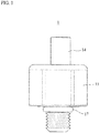
- FIG. 1 is a view illustrating a pressure sensor according to an embodiment
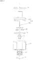
- FIG. 2 is an exploded view illustrating the pressure sensor according to an embodiment.
- a pressure sensor 1 may be fastened to a pressure measurement target to measure a pressure of a fluid flowing from the pressure measurement target and transmit the measured pressure to an external device.
- the pressure sensor 1 may include a sensor housing 11, a sensor header 12, a circuit board 13, a connector 14, a connecting terminal 15, an inner O-ring 16, and an outer O-ring 17.
- the sensor housing 11 and the sensor header 12 may be coupled to each other in a press-in manner while being machined to be cut separately.
- the sensor housing 11 may include a fastener 111 to be fastened to the pressure measurement target, and a housing pathway 112 (see FIG. 4 ) penetrating the fastener 111 to guide the fluid flowing from the pressure measurement target.
- the sensor header 12 is pressed in and fixed to the housing pathway 112.
- the sensor header 12 may be formed of a material having a higher yield stress than a material of the sensor housing 11. A configuration and an assembling process of the sensor header 12 will be described later with reference to FIGS. 3 and 4 .
- the circuit board 13 may transmit the measured signal from the sensor header 12 to the external device through the connector 14.
- the connector 14 may transmit the signal received from the circuit board 13 to the external device.
- the connector 14 may include a connector housing 141 to be connected to the sensor housing 11, and a connection terminal 142 to be positioned in the connector housing 141 and electrically connected to the circuit board 13.
- the connecting terminal 15 may be disposed between the circuit board 13 and the connection terminal 142 to electrically connect the circuit board 13 and the connection terminal 142.
- the connecting terminal 15 may have an elasticity in a direction perpendicular to the circuit board 13. As shown in FIG. 2 , the connecting terminal 15 may have a shape of C-clip.
- the inner O-ring 16 may be disposed between the connector housing 141 and the sensor housing 11 to maintain an airtightness between the connector housing 141 and the sensor housing 11, thereby preventing an inflow of a foreign substance.
- the inner O-ring 16 may be disposed along an outer edge of the connector housing 141 and an inner edge of a portal of the sensor housing 11.
- the outer O-ring 17 may be disposed, for example, in a circumferential direction of the fastener 111 of the connector housing 141.
- the outer O-ring 17 may maintain an airtightness between the pressure measurement target and the sensor housing 11, thereby preventing an inflow of a foreign substance.
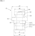
- FIG. 3 is a view illustrating a sensor header according to an embodiment
- F1G. 4 illustrates a cross-sectional view and a partially-enlarged view of a pressure sensor according to an embodiment.
- the sensor header 12 is pressed in and fixed to the sensor housing 11.
- the sensor header 12 and the sensor housing 11 may be formed of materials having different yield stresses, for example, metals having different yield stresses.
- the sensor housing 11 may be formed of an aluminum alloy, and the sensor header 12 may be formed of stainless steel having a higher yield stress than the aluminum alloy.
- one of the sensor header 12 and the sensor housing 11, the one formed of a material having a lower yield stress may be deformed such that a metal flow may be formed, during a process of pressing the sensor header 12 in the sensor housing 11 by applying a sufficient load thereto.
- the formed metal flow may be inserted into an empty space of the other one formed of a material having a higher yield stress, whereby the sensor header 12 and the sensor housing 11 may be coupled and in close contact in shapes to be airtight, without using a separate fastening element. That is, the sensor header 12 may be coupled to and sealed with the sensor housing 11, without using a separate airtight device such as an O-ring.
- a volume may change slightly as the temperature changes.
- a change in the airtightness level with respect to the temperature may be reduced.
- the total number of parts constituting the pressure sensor 1 may be reduced, whereby the production cost may be reduced, and the manufacturing process may be simplified.
- the sensor header 12 may include a port 121, a diaphragm 122, a flange 123, a connecting neck 124, a header pathway 125, and a strain gauge SG.
- the header pathway 125 penetrates the port 121.
- One end of the header pathway 125 may fluidly communicate with the housing pathway 112 to guide the fluid flowing from the housing pathway 112, and the other end thereof is covered by the diaphragm 122.
- the diaphragm 122 is positioned at the other end of the header pathway 125.
- the diaphragm 122 may have a shape of a thin plate to be deformed by the fluid flowing thereinto.
- the strain gauge SG may be attached to one surface, for example, a top surface, of the diaphragm 122.
- the strain gauge SG may convert a deformation level of the diaphragm 122 into an electrical signal, and transmit the electrical signal to the circuit board 13.
- the strain gauge SG may be formed of, for example, a silicon material.
- the port 121 is pressed in and fixed to the housing pathway 112.
- the port 121 may be formed of a material having a higher yield stress than the material of the sensor housing 11.
- the port 121 may include an insert 1211, a press-in part 1222, and a fixing groove 1223.
- the insert 1211 may be inserted into the housing pathway 112.
- a diameter d1 of the insert 1211 may be less than or equal to a diameter d6 of the housing pathway 112.
- the press-in part 1222 may be positioned behind the insert 1211 based on a direction in which the port 121 is inserted into the housing pathway 112, and pressed in the housing pathway 112.
- a diameter d2 of the press-in part 1222 may be greater than the diameter d1 of the insert 1211, and greater than the diameter d6 of the housing pathway 112.
- a yield stress of a material of the press-in part 1222 may be higher than a yield stress of a material of an inner end portion of the housing pathway 112.
- the fixing groove 1223 may be recessed between the insert 1211 and the press-in part 1222.
- a minimum diameter of the fixing groove 1223 may be less than the diameter d6 of the housing pathway 112.
- the flange 123 is positioned between the port 121 and the diaphragm 122, and have a diameter d4 greater than the maximum diameter d2 of the port 121 and a maximum diameter d3 of the diaphragm 122. Based on a place perpendicular to a longitudinal direction of the housing pathway 112 and/or the header pathway 125, a cross-sectional area of the flange 123 excluding the header pathway 125 may be greater than a maximum cross-sectional area of the port 121 excluding the header pathway 125. For example, the cross-sectional area of the flange 123 excluding the header pathway 125 may be at least two times greater than the maximum cross-sectional area of the port 121 excluding the header pathway 125.
- the flange 123 having relatively great cross-sectional area and volume may disperse the mechanical stress, thereby reducing an effect of the mechanical stress on an output of the pressure sensor 1.
- the connecting neck 124 may be disposed between the flange 123 and the diaphragm 122, and have a diameter less than the diameter d3 of the diaphragm 122 and the maximum diameter d2 of the port 121. Although there exists a portion of the mechanical stress dispersed while passing through the flange 123, the mechanical stress may be extinct while deforming the connecting neck 124 before being transmitted to the diaphragm 122. Hence, a miscellaneous load to be transmitted to the diaphragm 122 may be blocked.
- the sensor housing 11 includes a receiver 113 having a diameter d7 greater than the diameter d6 of the housing pathway 112, the receiver 113 to receive the flange 123, and a seat portion 114 positioned above the receiver 113, the seat portion 114 having a greater diameter than the receiver 113, the seat portion 114 to provide a space in which the circuit board 13 is seated.
- the receiver 113 may include a bottom surface 113a connected to the housing pathway 112, and an inner circumferential surface 113b to enclose a circumference of the bottom surface 113a.
- the flange 123 is a distance L1 spaced apart from the bottom surface 113a of the receiver 113.
- the distance L1 may be, for example, 0.5 millimeters (mm).
- the diameter d7 of the receiver 113 may be a distance L2 greater than the diameter of the flange 123.
- the flange 123 may be the distance L2 spaced apart from the inner circumferential surface 113b of the receiver 113.
- the distance L2 may be, for example, 1 mm.
- the circuit board 13 may be seated in the seat portion 114 of the sensor housing 11.
- the circuit board 13 may include a sensor hole 131 formed to have a diameter greater than the diameter of the diaphragm 122.
- the diaphragm 122 may be positioned at a center of the sensor hole 131.
- the strain gauge SG and the circuit board 13 may be electrically connected easily, while the sensor header 12 and the circuit board 13 are sequentially assembled with the sensor housing 11.
- the strain gauge SG and the circuit board 13 may be connected to each other by wire bonding.
- FIG. 5 illustrates a process of pressing a sensor header in a sensor housing using an exclusive jig according to an embodiment.
- an exclusive jig 2 may pressurize the flange 123 without pressurizing the diaphragm 122 of the sensor header 12.
- the exclusive jig 2 may include a pressurizing plate 21 and a pressurizing protrusion 22.
- the pressurizing plate 21 may be spaced apart from the diaphragm 122 when the exclusive jig 2 is in contact with the flange 123.
- the pressurizing plate 21 may have a flat top surface such that a pressurizing device to pressurize the exclusive jig 2 may provide a uniform pressure to the exclusive jig 2.
- the pressurizing protrusion 22 may protrude from the pressurizing plate 21, and have a protruding length greater than a distance from a top surface of the flange 123 to a top surface of the diaphragm 122 in the example of FIG. 5 .
- the pressurizing protrusion 22 may have a symmetric shape about a center of the pressurizing plate 21, for example, a hollow cylindrical shape.
- the shape of the pressurizing protrusion 22 is not limited to the cylindrical shape.
- the pressurizing protrusion 22 may have a shape of a plurality of columns disposed along an edge of the pressurizing plate 21.
- a distance from the center of the pressurizing plate 21 to an inner wall of the pressurizing protrusion 22 may be greater than a distance from the center of the diaphragm 122 to an edge of the diaphragm 122.
- FIG. 6 is a flowchart illustrating a method of manufacturing a pressure sensor according to an embodiment.
- a method of manufacturing the pressure sensor 1 may include operation 91 of aligning the sensor header 12 with the sensor housing 11, operation 92 of pressing the sensor header 12 in using the exclusive jig 2, operation 93 of assembling the circuit board 13 with the sensor housing 11, operation 94 of electrically connecting the diaphragm 122 and the circuit board 13, and operation 95 of assembling the connector 14 with the sensor housing 11.
- the port 121 of the sensor header 12 may be aligned with the housing pathway 112 of the sensor housing 11.
- the insert 1211 and the fixing groove 1223 each having the diameter less than or equal to the diameter of the housing pathway 112, among the port 121 of the sensor header 12, may be inserted into the housing pathway 112, and the press-in part 1222 having the diameter greater than the diameter of the housing pathway 112 may be aligned while being stopped by the portal of the housing pathway 112.
- the port 121 may be pressed in the housing pathway 112 by pressurizing the flange 123 of the sensor header 12.
- a worker may pressurize the flange 123 using the exclusive jig 2 as shown in FIG. 5 .
- the worker may pressurize the exclusive jig 2 using a pressurizing device capable of position control and/or load sensing, for example, a servo press.
- the worker may control the flange 123 to be stopped at a position spaced apart from the bottom surface 113a of the receiver 113 based on a predetermined value. Further, the worker may easily perform quality control based on a load pattern during pressurization and a pressurizing depth of the sensor header 12.
- the circuit board 13 may be seated in the sensor housing 11, the circuit board 13 to transmit, to an external device, a signal measured from the strain gauge SG disposed on the diaphragm 122 of the sensor header 12. While the circuit board 13 is seated in the sensor housing 11, the circuit board 13 and the strain gauge SG may be connected to each other by wire bonding.
- the connector 14 including the connection terminal 142 to be electrically connected to the circuit board 13 may be assembled with the sensor housing 11, in operation 94.
- a pressure sensor according to an embodiment is manufactured by pressing a sensor header in a sensor housing.
- the total number of parts constituting the pressure sensor may be reduced, a manufacturing cost and time may be reduced, and a durability of the pressure sensor including a sealing capability may improve. Further, corrosion of the O-ring by a fluid flowing into the pressure sensor may be prevented. In addition, an effect of a change in mechanical stress on an output of the pressure sensor, the mechanical stress applied to the pressure sensor caused by a change in compressive force in response to aging of the O-ring, may be prevented.
- the pressure sensor may prevent an effect of the mechanical stress generated during the press-in process of the sensor header or a miscellaneous load on a diaphragm of the sensor header, whereby an accuracy of the pressure sensor may improve.
- a flange of the sensor header of the pressure sensor may be spaced apart from an inner wall of the sensor housing, thereby preventing an error of the pressure sensor caused by a volume change occurring in response to a change in temperature of the pressure sensor.
Description
- Embodiments relate to a pressure sensor and a manufacturing method therefor.
- A sensor refers to a part, device or instrument that senses or detects and measures a physical quantity of heat, light, temperature, pressure or sound or a change therein and sends the corresponding information as a predetermined signal, or a device or part that senses five senses of humans, such as sight and hearing. A pressure sensor may sense a pressure. A prior art pressure sensor (on which the preamble of
claim 1 is based) is disclosed in utility modelCN 203616040 U . The sensor includes a soft metal body in which a harder metal seat is press-fitted such that a portion of the soft metal body yields and enters a groove in an exterior of the metal seat. A passage in the metal body communicates with a passage in the metal seat which is closed by a diaphragm portion of the metal seat on which a sensing head is positioned. A similar pressure sensor is disclosed in patentDE 10302281 A1 . In patentUS 2005/0097721 A1 a prior art pressure sensor pressure port of stainless steel which is press-fitted into an aluminum baseplate is disclosed. In its finally installed position a flat shoulder of the pressure port abuts the baseplate to indicate that the pressure port has been fully seated. A further pressure sensor, with multiple components positioned between a sensor housing and a sensing element thereof is disclosed in patentUS 6457368 B1 . A further pressure sensor is disclosed in patentKR 10-2013-0042300 A - An aspect provides a pressure sensor that may be simply manufactured and a manufacturing method therefor.
- According to the invention there is provided a pressure sensor according to
claim 1. - The port may be formed of a material having a higher yield stress than a material of the sensor housing.
- The port may include an insert to be inserted into the housing pathway, a press-in part positioned behind the insert based on a direction in which the port is inserted into the housing pathway, the press-in part having a diameter greater than a diameter of the housing pathway, and a fixing groove recessed between the insert and the press-in part, the fixing groove having a minimum diameter less than the diameter of the housing pathway, the fixing groove configured to prevent a separation of the port from the housing pathway by receiving a metal flow formed at an inner end portion of the housing pathway while the press-in part is being pressed in the housing pathway.
- The sensor header includes a flange positioned between the port and the diaphragm, the flange having a diameter greater than a diameter of the port and a diameter of the diaphragm.
- A cross-sectional area of the flange may be greater than a maximum cross-sectional area of the port based on a plane perpendicular to a longitudinal direction of the housing pathway.
- The sensor housing includes a receiver having a diameter greater than the diameter of the housing pathway, the receiver receiving the flange.
- The diameter of the receiver may be greater than the diameter of the flange.
- The flange is disposed to be spaced apart from a bottom surface of the receiver when the sensor header is completely fastened to the sensor housing.
- The sensor header may further include a connecting neck disposed between the flange and the diaphragm, the connecting neck having a diameter less than a maximum diameter of the diaphragm and a maximum diameter of the port.
- The pressure sensor may further include a circuit board including a sensor hole formed to have a diameter greater than a diameter of the diaphragm. The diaphragm may be positioned at a center of the sensor hole, and a strain gauge attached to the diaphragm and the circuit board may be electrically connected to each other by wire bonding.
- The pressure sensor may further include a connector configured to transmit a signal received from the circuit board to an external device, and the connector may include a connector housing to be connected to the sensor housing, and a connection terminal to be positioned in the connector housing and electrically connected to the circuit board.
- The pressure sensor may further include a connecting terminal having an elasticity in a direction perpendicular to the circuit board, the connecting terminal configured to connect the circuit board and the connection terminal.
- According to the invention there is also provided a method, as set out in the independent method claim 9, of manufacturing a pressure sensor.
- The pressing may be performed using an exclusive jig configured to pressurize the flange without pressurizing a diaphragm of the sensor header.
- The exclusive jig may include a pressurizing plate, and a pressurizing protrusion protruding from the pressurizing plate and having a protruding length greater than a distance from a top surface of the flange to a top surface of the diaphragm.
- A distance from a center of the pressurizing plate to an inner wall of the pressurizing protrusion may be greater than a distance from a center of the diaphragm to an edge of the diaphragm.
- The method may further include assembling a circuit board with the sensor housing after the pressing, the circuit board configured to transmit, to an external device, a signal measured from a stain gauge disposed on a diaphragm of the sensor header, and wire-bonding the circuit board and the strain gauge after the assembling. The circuit board may include a sensor hole formed to have a diameter greater than a diameter of the diaphragm.
- The method may further include assembling a connector with the sensor housing after the wire-bonding, the connector including a connection terminal to be electrically connected to the circuit board, and installing a connecting terminal on the circuit board before the assembling of the circuit board with the sensor housing, the connecting terminal configured to electrically connect the connection terminal and the circuit board. The connecting terminal may have an elasticity in a direction perpendicular to the circuit board.
- According to an embodiment, a pressure sensor may be manufactured by pressing a sensor header in a sensor housing. When compared to a pressure sensor including an O-ring inserted between a sensor housing and a sensor header, the total number of parts constituting the pressure sensor may be reduced, a manufacturing cost and time may be reduced, and a durability of the pressure sensor including a sealing capability may improve. Further, corrosion of the O-ring by a fluid flowing into the pressure sensor may be prevented. In addition, an effect of a change in mechanical stress on an output of the pressure sensor, the mechanical stress applied to the pressure sensor caused by a change in compressive force in response to aging of the O-ring, may be prevented.
- According to an embodiment, due to a structural feature of a sensor header, a pressure sensor may prevent an effect of a mechanical stress generated during a press-in process of the sensor header or a miscellaneous load on a diaphragm of the sensor header, whereby an accuracy of the pressure sensor may improve.
- According to an embodiment, a flange of a sensor header of a pressure sensor may be spaced apart from an inner wall of a sensor housing, thereby preventing an error of the pressure sensor caused by a volume change occurring in response to a change in temperature of the pressure sensor.
-
-
FIG. 1 is a view illustrating a pressure sensor according to an embodiment. -
FIG. 2 is an exploded view illustrating a pressure sensor according to an embodiment. -
FIG. 3 is a view illustrating a sensor header according to an embodiment. -
FIG. 4 illustrates a cross-sectional view and a partially-enlarged view of a pressure sensor according to an embodiment. -
FIG. 5 illustrates a process of pressing a sensor header in a sensor housing using an exclusive jig according to an embodiment. -
FIG. 6 is a flowchart illustrating a method of manufacturing a pressure sensor according to an embodiment. - Hereinafter, some embodiments will be described in detail with reference to the accompanying drawings. Regarding the reference numerals assigned to the elements in the drawings, it should be noted that the same elements will be designated by the same reference numerals, wherever possible, even though they are shown in different drawings. Also, in the description of embodiments, detailed description of well-known related structures or functions will be omitted when it is deemed that such description will cause ambiguous interpretation of the present disclosure.
- In addition, terms such as first, second, A, B, (a), (b), and the like may be used herein to describe components. Each of these terminologies is not used to define an essence, order or sequence of a corresponding component but used merely to distinguish the corresponding component from other component(s).
- It should be noted that if it is described in the specification that one component is "connected", "coupled", or "joined" to another component, a third component may be "connected", "coupled", and "joined" between the first and second components, although the first component may be directly connected, coupled or joined to the second component.
-
FIG. 1 is a view illustrating a pressure sensor according to an embodiment, andFIG. 2 is an exploded view illustrating the pressure sensor according to an embodiment. - Referring to
FIGS. 1 and2 , apressure sensor 1 may be fastened to a pressure measurement target to measure a pressure of a fluid flowing from the pressure measurement target and transmit the measured pressure to an external device. Thepressure sensor 1 may include asensor housing 11, asensor header 12, acircuit board 13, aconnector 14, a connectingterminal 15, an inner O-ring 16, and an outer O-ring 17. For example, the sensor housing 11 and thesensor header 12 may be coupled to each other in a press-in manner while being machined to be cut separately. - The
sensor housing 11 may include afastener 111 to be fastened to the pressure measurement target, and a housing pathway 112 (seeFIG. 4 ) penetrating thefastener 111 to guide the fluid flowing from the pressure measurement target. - The
sensor header 12 is pressed in and fixed to thehousing pathway 112. Thesensor header 12 may be formed of a material having a higher yield stress than a material of thesensor housing 11. A configuration and an assembling process of thesensor header 12 will be described later with reference toFIGS. 3 and4 . - The
circuit board 13 may transmit the measured signal from thesensor header 12 to the external device through theconnector 14. - The
connector 14 may transmit the signal received from thecircuit board 13 to the external device. Theconnector 14 may include aconnector housing 141 to be connected to thesensor housing 11, and aconnection terminal 142 to be positioned in theconnector housing 141 and electrically connected to thecircuit board 13. - The connecting
terminal 15 may be disposed between thecircuit board 13 and theconnection terminal 142 to electrically connect thecircuit board 13 and theconnection terminal 142. The connectingterminal 15 may have an elasticity in a direction perpendicular to thecircuit board 13. As shown inFIG. 2 , the connectingterminal 15 may have a shape of C-clip. By the above structure, even in a case in which there exist a manufacturing tolerance and an assembling tolerance of thecircuit board 13 and/or theconnection terminal 142, an electrical contact state of thecircuit board 13 and theconnection terminal 142 may be stably secured. - The inner O-
ring 16 may be disposed between theconnector housing 141 and thesensor housing 11 to maintain an airtightness between theconnector housing 141 and thesensor housing 11, thereby preventing an inflow of a foreign substance. For example, the inner O-ring 16 may be disposed along an outer edge of theconnector housing 141 and an inner edge of a portal of thesensor housing 11. - The outer O-
ring 17 may be disposed, for example, in a circumferential direction of thefastener 111 of theconnector housing 141. - The outer O-
ring 17 may maintain an airtightness between the pressure measurement target and thesensor housing 11, thereby preventing an inflow of a foreign substance. -
FIG. 3 is a view illustrating a sensor header according to an embodiment, and F1G. 4 illustrates a cross-sectional view and a partially-enlarged view of a pressure sensor according to an embodiment. - Referring to
FIGS. 3 and4 , thesensor header 12 is pressed in and fixed to thesensor housing 11. Thesensor header 12 and thesensor housing 11 may be formed of materials having different yield stresses, for example, metals having different yield stresses. For example, thesensor housing 11 may be formed of an aluminum alloy, and thesensor header 12 may be formed of stainless steel having a higher yield stress than the aluminum alloy. By the above design, one of thesensor header 12 and thesensor housing 11, the one formed of a material having a lower yield stress, may be deformed such that a metal flow may be formed, during a process of pressing thesensor header 12 in thesensor housing 11 by applying a sufficient load thereto. The formed metal flow may be inserted into an empty space of the other one formed of a material having a higher yield stress, whereby thesensor header 12 and thesensor housing 11 may be coupled and in close contact in shapes to be airtight, without using a separate fastening element. That is, thesensor header 12 may be coupled to and sealed with thesensor housing 11, without using a separate airtight device such as an O-ring. By the above manner, a volume may change slightly as the temperature changes. Thus, a change in the airtightness level with respect to the temperature may be reduced. Further, the total number of parts constituting thepressure sensor 1 may be reduced, whereby the production cost may be reduced, and the manufacturing process may be simplified. In addition, an effect of a miscellaneous load generated during an assembling process on a sensor may be reduced. Thesensor header 12 may include aport 121, adiaphragm 122, aflange 123, a connectingneck 124, aheader pathway 125, and a strain gauge SG. - The
header pathway 125 penetrates theport 121. One end of theheader pathway 125 may fluidly communicate with thehousing pathway 112 to guide the fluid flowing from thehousing pathway 112, and the other end thereof is covered by thediaphragm 122. - The
diaphragm 122 is positioned at the other end of theheader pathway 125. Thediaphragm 122 may have a shape of a thin plate to be deformed by the fluid flowing thereinto. The strain gauge SG may be attached to one surface, for example, a top surface, of thediaphragm 122. The strain gauge SG may convert a deformation level of thediaphragm 122 into an electrical signal, and transmit the electrical signal to thecircuit board 13. The strain gauge SG may be formed of, for example, a silicon material. - The
port 121 is pressed in and fixed to thehousing pathway 112. For example, theport 121 may be formed of a material having a higher yield stress than the material of thesensor housing 11. Theport 121 may include aninsert 1211, a press-inpart 1222, and a fixinggroove 1223. - The
insert 1211 may be inserted into thehousing pathway 112. A diameter d1 of theinsert 1211 may be less than or equal to a diameter d6 of thehousing pathway 112. - The press-in
part 1222 may be positioned behind theinsert 1211 based on a direction in which theport 121 is inserted into thehousing pathway 112, and pressed in thehousing pathway 112. A diameter d2 of the press-inpart 1222 may be greater than the diameter d1 of theinsert 1211, and greater than the diameter d6 of thehousing pathway 112. Further, a yield stress of a material of the press-inpart 1222 may be higher than a yield stress of a material of an inner end portion of thehousing pathway 112. By the above structure, the inner end portion of thehousing pathway 112 may be deformed while the press-inpart 1222 is being pressed in thehousing pathway 112 such that a metal flow may be formed. A portion deformed in a form of the metal flow, among the inner end portion of thehousing pathway 112, may be referred to as adeformed portion 112a. - The fixing
groove 1223 may be recessed between theinsert 1211 and the press-inpart 1222. A minimum diameter of the fixinggroove 1223 may be less than the diameter d6 of thehousing pathway 112. By the above structure, thedeformed portion 112a of thehousing pathway 112 may be deformed in a form of a metal flow and fill the fixinggroove 1223 while the press-inpart 1222 is being pressed in thehousing pathway 112, thereby preventing a separation of theport 121 from thehousing pathway 112. - The
flange 123 is positioned between theport 121 and thediaphragm 122, and have a diameter d4 greater than the maximum diameter d2 of theport 121 and a maximum diameter d3 of thediaphragm 122. Based on a place perpendicular to a longitudinal direction of thehousing pathway 112 and/or theheader pathway 125, a cross-sectional area of theflange 123 excluding theheader pathway 125 may be greater than a maximum cross-sectional area of theport 121 excluding theheader pathway 125. For example, the cross-sectional area of theflange 123 excluding theheader pathway 125 may be at least two times greater than the maximum cross-sectional area of theport 121 excluding theheader pathway 125. By the above structure, during a process of transmitting, to thediaphragm 122, a mechanical stress generated in a vicinity of the press-inpart 1222 when the press-inpart 1222 is completely pressed in thehousing pathway 112, theflange 123 having relatively great cross-sectional area and volume may disperse the mechanical stress, thereby reducing an effect of the mechanical stress on an output of thepressure sensor 1. - The connecting
neck 124 may be disposed between theflange 123 and thediaphragm 122, and have a diameter less than the diameter d3 of thediaphragm 122 and the maximum diameter d2 of theport 121. Although there exists a portion of the mechanical stress dispersed while passing through theflange 123, the mechanical stress may be extinct while deforming the connectingneck 124 before being transmitted to thediaphragm 122. Hence, a miscellaneous load to be transmitted to thediaphragm 122 may be blocked. - Meanwhile, the
sensor housing 11 includes areceiver 113 having a diameter d7 greater than the diameter d6 of thehousing pathway 112, thereceiver 113 to receive theflange 123, and aseat portion 114 positioned above thereceiver 113, theseat portion 114 having a greater diameter than thereceiver 113, theseat portion 114 to provide a space in which thecircuit board 13 is seated. Thereceiver 113 may include abottom surface 113a connected to thehousing pathway 112, and an innercircumferential surface 113b to enclose a circumference of thebottom surface 113a. - When the
sensor header 12 is completely fastened to thesensor housing 11 as shown inFIG. 4 , theflange 123 is a distance L1 spaced apart from thebottom surface 113a of thereceiver 113. The distance L1 may be, for example, 0.5 millimeters (mm). By the above structure, although thesensor header 12 and thesensor housing 11 formed of different materials expand by heat with different degrees in response to a change in the peripheral temperature, interference of theflange 123 with thebottom surface 113a of thereceiver 113 may be prevented. Hence, by the above structure, transmission of an undesired mechanical stress to thediaphragm 122 due to a volume change caused by the change in the peripheral temperature of thepressure sensor 1 may be prevented, whereby a measuring accuracy of thepressure sensor 1 may improve. - The diameter d7 of the
receiver 113 may be a distance L2 greater than the diameter of theflange 123. When thesensor header 12 is completely fastened to thesensor housing 11 as shown inFIG. 4 , theflange 123 may be the distance L2 spaced apart from the innercircumferential surface 113b of thereceiver 113. The distance L2 may be, for example, 1 mm. By the above structure, although thesensor header 12 and thesensor housing 11 formed of different materials expand by heat with different degrees in response to a change in the peripheral temperature, interference of theflange 123 with the innercircumferential surface 113b of thereceiver 113 may be prevented. Hence, by the above structure, transmission of an undesired mechanical stress to thediaphragm 122 due to a volume change caused by the change in the peripheral temperature of thepressure sensor 1 may be prevented, whereby the measuring accuracy of thepressure sensor 1 may improve. - Meanwhile, the
circuit board 13 may be seated in theseat portion 114 of thesensor housing 11. Thecircuit board 13 may include asensor hole 131 formed to have a diameter greater than the diameter of thediaphragm 122. When thecircuit board 13 is seated in theseat portion 114, thediaphragm 122 may be positioned at a center of thesensor hole 131. - By the above structure, the strain gauge SG and the
circuit board 13 may be electrically connected easily, while thesensor header 12 and thecircuit board 13 are sequentially assembled with thesensor housing 11. For example, the strain gauge SG and thecircuit board 13 may be connected to each other by wire bonding. -
FIG. 5 illustrates a process of pressing a sensor header in a sensor housing using an exclusive jig according to an embodiment. - Referring to
FIG. 5 , anexclusive jig 2 may pressurize theflange 123 without pressurizing thediaphragm 122 of thesensor header 12. Theexclusive jig 2 may include a pressurizingplate 21 and a pressurizingprotrusion 22. - The pressurizing
plate 21 may be spaced apart from thediaphragm 122 when theexclusive jig 2 is in contact with theflange 123. For example, the pressurizingplate 21 may have a flat top surface such that a pressurizing device to pressurize theexclusive jig 2 may provide a uniform pressure to theexclusive jig 2. - The pressurizing
protrusion 22 may protrude from the pressurizingplate 21, and have a protruding length greater than a distance from a top surface of theflange 123 to a top surface of thediaphragm 122 in the example ofFIG. 5 . The pressurizingprotrusion 22 may have a symmetric shape about a center of the pressurizingplate 21, for example, a hollow cylindrical shape. However, the shape of the pressurizingprotrusion 22 is not limited to the cylindrical shape. For example, the pressurizingprotrusion 22 may have a shape of a plurality of columns disposed along an edge of the pressurizingplate 21. - A distance from the center of the pressurizing
plate 21 to an inner wall of the pressurizingprotrusion 22 may be greater than a distance from the center of thediaphragm 122 to an edge of thediaphragm 122. By the above shape, interference of theexclusive jig 2 with thediaphragm 122 while theexclusive jig 2 is pressurizing theflange 123 may be prevented, whereby transmission of a mechanical stress to thediaphragm 122 may be prevented. -
FIG. 6 is a flowchart illustrating a method of manufacturing a pressure sensor according to an embodiment. - Referring to
FIGS. 1 through 6 , a method of manufacturing thepressure sensor 1 may includeoperation 91 of aligning thesensor header 12 with thesensor housing 11,operation 92 of pressing thesensor header 12 in using theexclusive jig 2,operation 93 of assembling thecircuit board 13 with thesensor housing 11,operation 94 of electrically connecting thediaphragm 122 and thecircuit board 13, andoperation 95 of assembling theconnector 14 with thesensor housing 11. - First, in
operation 91, theport 121 of thesensor header 12 may be aligned with thehousing pathway 112 of thesensor housing 11. For example, theinsert 1211 and the fixinggroove 1223 each having the diameter less than or equal to the diameter of thehousing pathway 112, among theport 121 of thesensor header 12, may be inserted into thehousing pathway 112, and the press-inpart 1222 having the diameter greater than the diameter of thehousing pathway 112 may be aligned while being stopped by the portal of thehousing pathway 112. - Next, in
operation 92, theport 121 may be pressed in thehousing pathway 112 by pressurizing theflange 123 of thesensor header 12. For example, a worker may pressurize theflange 123 using theexclusive jig 2 as shown inFIG. 5 . The worker may pressurize theexclusive jig 2 using a pressurizing device capable of position control and/or load sensing, for example, a servo press. By the above method, the worker may control theflange 123 to be stopped at a position spaced apart from thebottom surface 113a of thereceiver 113 based on a predetermined value. Further, the worker may easily perform quality control based on a load pattern during pressurization and a pressurizing depth of thesensor header 12. - Next, in
operation 93, thecircuit board 13 may be seated in thesensor housing 11, thecircuit board 13 to transmit, to an external device, a signal measured from the strain gauge SG disposed on thediaphragm 122 of thesensor header 12. While thecircuit board 13 is seated in thesensor housing 11, thecircuit board 13 and the strain gauge SG may be connected to each other by wire bonding. - After the wire bonding of the
circuit board 13 and the strain gauge SG, theconnector 14 including theconnection terminal 142 to be electrically connected to thecircuit board 13 may be assembled with thesensor housing 11, inoperation 94. - Meanwhile, after
operation 93 and beforeoperation 94, an operation of installing the connectingterminal 15 on thecircuit board 13, the connectingterminal 15 to electrically connect theconnection terminal 142 and thecircuit board 13, may be performed. - A pressure sensor according to an embodiment is manufactured by pressing a sensor header in a sensor housing.
- When compared to a pressure sensor including an O-ring inserted between a sensor housing and a sensor header, the total number of parts constituting the pressure sensor may be reduced, a manufacturing cost and time may be reduced, and a durability of the pressure sensor including a sealing capability may improve. Further, corrosion of the O-ring by a fluid flowing into the pressure sensor may be prevented. In addition, an effect of a change in mechanical stress on an output of the pressure sensor, the mechanical stress applied to the pressure sensor caused by a change in compressive force in response to aging of the O-ring, may be prevented.
- Due to a structural feature of the sensor header, the pressure sensor may prevent an effect of the mechanical stress generated during the press-in process of the sensor header or a miscellaneous load on a diaphragm of the sensor header, whereby an accuracy of the pressure sensor may improve. A flange of the sensor header of the pressure sensor may be spaced apart from an inner wall of the sensor housing, thereby preventing an error of the pressure sensor caused by a volume change occurring in response to a change in temperature of the pressure sensor.
Claims (12)
- A pressure sensor (1), comprising:a sensor housing (11) including a fastener (111) to be fastened to a pressure measurement target, and a housing pathway (112) configured to penetrate the fastener (111) and guide a fluid flowing from the pressure measurement target; anda sensor header (12) including a port (121) pressed in and fixed to the housing pathway (112), a header pathway (125) configured to penetrate the port (121) and guide the fluid flowing from the housing pathway (112), and a diaphragm (122) positioned at an end portion of the header pathway (125),wherein the sensor header (12) further includes a flange (123) positioned between the port (121) and the diaphragm (122), the flange (123) having a diameter (d4) greater than a diameter of the port (121) and a diameter of the diaphragm (122), andwherein the sensor housing (11) further includes a receiver recess (113) receiving the flange (123) and having: (i) a diameter (d7) greater than the diameter (d6) of the housing pathway (112); (ii) a bottom surface (113a), an inner edge of which is connected to the housing pathway (112); and (iii) an inner circumferential surface (113b) connected to and enclosing a circumference of the bottom surface (113a),characterised in that the flange (123) is disposed spaced apart from the bottom surface (113a) of the receiver recess (113).
- The pressure sensor (1) of claim 1, wherein the port (121) is formed of a material having a higher yield stress than a material of the sensor housing (11).
- The pressure sensor (1) of claim 2, wherein the port (121) includes:an insert (1211) to be inserted into the housing pathway (112);a press-in part (1222) positioned behind the insert (1211) based on a direction in which the port (121) is inserted into the housing pathway (112), the press-in part (1222) having a diameter (d2) greater than the diameter (d6) of the housing pathway (112); anda fixing groove (1223) recessed between the insert (1211) and the press-in part (1222), the fixing groove (1223) having a minimum diameter less than the diameter of the housing pathway (112), the fixing groove (1223) configured to prevent a separation of the port (121) from the housing pathway (112) by receiving a metal flow formed at an inner end portion of the housing pathway (112) while the press-in part (1222) is being pressed in the housing pathway (112).
- The pressure sensor (1) of claim 1, wherein a cross-sectional area of the flange (123) is greater than a maximum cross-sectional area of the port (121) based on a plane perpendicular to a longitudinal direction of the housing pathway (112).
- The pressure sensor (1) of claim 1, wherein the sensor header (12) further includes a connecting neck (124) disposed between the flange (123) and the diaphragm (122), the connecting neck (124) having a diameter less than a maximum diameter (d3) of the diaphragm (122) and a maximum diameter (d2) of the port (121).
- The pressure sensor (1) of claim 1, further comprising:a circuit board (13) including a sensor hole formed to have a diameter greater than a diameter (d3) of the diaphragm (122),wherein the diaphragm (122) is positioned at a center of the sensor hole, anda strain gauge (SG) attached to the diaphragm (122) and the circuit board (13) are electrically connected to each other by wire bonding.
- The pressure sensor (1) of claim 6, further comprising:a connector (14) configured to transmit a signal received from the circuit board (13) to an external device,wherein the connector (14) includes:a connector housing (141) to be connected to the sensor housing (11); anda connection terminal (142) to be positioned in the connector housing (141) and electrically connected to the circuit board (13).
- The pressure sensor (1) of claim 7, further comprising:
a connecting terminal (15) having an elasticity in a direction perpendicular to the circuit board (13), the connecting terminal (15) configured to connect the circuit board (13) and the connection terminal (142). - A method of manufacturing a pressure sensor (1) according to claim 1, the method comprising:aligning the port (121) of the sensor header (12) with the housing pathway (112) of the sensor housing (11) the sensor header (12) further including the flange (123) positioned between the port (121) and the diaphragm (122) of the sensor header (12), the flange having the diameter (d4) greater than the diameter of the port (121) and the diameter of the diaphragm (122), the sensor housing (11) further including the receiver recess (113) having the diameter (d7) greater than the diameter (d6) of the housing pathway (12), the receiver recess (113) configured to receive the flange (123); andpressing the port (121) in the housing pathway (112) by pressurizing the flange (123) of the sensor header (12),wherein the port (121) has the greater diameter (d2) than the housing pathway (112), and the flange (123) has the diameter (d4) greater than the diameter (d2) of the port (121),characterised in that, when the sensor header (12) is completely fastened to the sensor housing (11) the flange (123) is disposed spaced apart from a bottom surface (113a) of the receiver recess (113).
- The method of claim 9, wherein the pressing is performed using an exclusive jig configured to pressurize the flange (123) without pressurizing a diaphragm (122) of the sensor header (12).
- The method of claim 9, further comprising:assembling a circuit board (13) with the sensor housing (11) after the pressing, the circuit board (13) configured to transmit, to an external device, a signal measured from a strain gauge (SG) disposed on a diaphragm (122) of the sensor header (12); andwire-bonding the circuit board (13) and the strain gauge (SG) after the assembling,wherein the circuit board (13) includes a sensor hole formed to have a diameter greater than a diameter of the diaphragm (122).
- The method of claim 11, further comprising:assembling a connector (14) with the sensor housing (11) after the wire-bonding, the connector (14) including a connection terminal (142) to be electrically connected to the circuit board (13); andinstalling a connecting terminal (15) on the circuit board (13) before the assembling of the circuit board (13) with the sensor housing (11), the connecting terminal (15) configured to electrically connect the connection terminal (142) and the circuit board (13),wherein the connecting terminal (15) has an elasticity in a direction perpendicular to the circuit board (13).
Applications Claiming Priority (2)
| Application Number | Priority Date | Filing Date | Title |
|---|---|---|---|
| KR20150188662 | 2015-12-29 | ||
| PCT/KR2016/015353 WO2017116122A1 (en) | 2015-12-29 | 2016-12-28 | Pressure sensor and manufacturing method therefor |
Publications (3)
| Publication Number | Publication Date |
|---|---|
| EP3399295A1 EP3399295A1 (en) | 2018-11-07 |
| EP3399295A4 EP3399295A4 (en) | 2019-08-28 |
| EP3399295B1 true EP3399295B1 (en) | 2021-09-22 |
Family
ID=59225292
Family Applications (1)
| Application Number | Title | Priority Date | Filing Date |
|---|---|---|---|
| EP16882074.4A Active EP3399295B1 (en) | 2015-12-29 | 2016-12-28 | Pressure sensor and manufacturing method therefor |
Country Status (5)
| Country | Link |
|---|---|
| EP (1) | EP3399295B1 (en) |
| JP (1) | JP6865223B2 (en) |
| KR (1) | KR102597323B1 (en) |
| CN (1) | CN108474706B (en) |
| WO (1) | WO2017116122A1 (en) |
Families Citing this family (1)
| Publication number | Priority date | Publication date | Assignee | Title |
|---|---|---|---|---|
| KR102119120B1 (en) * | 2018-11-19 | 2020-06-04 | 세종공업 주식회사 | Plastic housing package for pressure sensor |
Family Cites Families (20)
| Publication number | Priority date | Publication date | Assignee | Title |
|---|---|---|---|---|
| JPS6117925A (en) * | 1984-07-05 | 1986-01-25 | Hitachi Ltd | Pressure sensor |
| RU2041453C1 (en) * | 1986-01-06 | 1995-08-09 | Научно-исследовательский институт физических измерений | Pressure transducer |
| JP2001133345A (en) * | 1999-11-02 | 2001-05-18 | Fuji Koki Corp | Pressure sensor |
| JP2002071495A (en) * | 2000-08-28 | 2002-03-08 | Saginomiya Seisakusho Inc | Structure and method for mounting diaphragm member of pressure sensor |
| DE10302281A1 (en) * | 2002-08-29 | 2004-03-04 | Continental Teves Ag & Co. Ohg | Pressure sensor module for electro-hydraulic car brakes, has pressure sensor in hard mount forced into soft housing to make sealed joint |
| JP4774678B2 (en) * | 2003-08-29 | 2011-09-14 | 富士電機株式会社 | Pressure sensor device |
| US20050097721A1 (en) * | 2003-11-06 | 2005-05-12 | Bratek Daniel J. | High pressure sensor with knurl press-fit assembly |
| JP3976015B2 (en) * | 2004-02-04 | 2007-09-12 | 株式会社デンソー | Pressure sensor |
| JP4227550B2 (en) * | 2004-03-29 | 2009-02-18 | 長野計器株式会社 | Pressure sensor and manufacturing method thereof |
| CN100541157C (en) * | 2004-03-30 | 2009-09-16 | 株式会社电装 | Pressure transducer |
| JP2006258471A (en) * | 2005-03-15 | 2006-09-28 | Denso Corp | Pressure sensor |
| US8371175B2 (en) * | 2009-10-01 | 2013-02-12 | Rosemount Inc. | Pressure transmitter with pressure sensor mount |
| KR101303197B1 (en) * | 2011-10-18 | 2013-09-04 | 김광식 | Pressure sensor and method for manufacturing thereof |
| KR102000294B1 (en) * | 2012-09-28 | 2019-07-15 | 타이코에이엠피 주식회사 | Pressure sensor |
| KR102000293B1 (en) * | 2012-09-28 | 2019-07-15 | 타이코에이엠피 주식회사 | Pressure sensor |
| RU2517798C1 (en) * | 2012-12-03 | 2014-05-27 | Открытое акционерное общество "Научно-исследовательский институт физических измерений" | Strain gage pressure sensor based on thin-film nano- and microelectromechanical system |
| CN203616040U (en) * | 2013-12-03 | 2014-05-28 | 新会康宇测控仪器仪表工程有限公司 | Piezoresistive sensor with metal flow sealing structure |
| DE102014104113A1 (en) * | 2014-03-25 | 2015-10-01 | Kavlico GmbH | Pressure sensor for hydrogen applications |
| KR101573367B1 (en) * | 2014-05-12 | 2015-12-03 | 전자부품연구원 | Piezoresistive typed ceramic pressure sensor |
| CN104316252A (en) * | 2014-10-14 | 2015-01-28 | 秦川机床集团宝鸡仪表有限公司 | Split type hammering union fracturing mud pressure transmitter |
-
2016
- 2016-12-28 CN CN201680077282.2A patent/CN108474706B/en active Active
- 2016-12-28 JP JP2018533916A patent/JP6865223B2/en active Active
- 2016-12-28 WO PCT/KR2016/015353 patent/WO2017116122A1/en active Application Filing
- 2016-12-28 EP EP16882074.4A patent/EP3399295B1/en active Active
- 2016-12-28 KR KR1020167036678A patent/KR102597323B1/en active IP Right Grant
Also Published As
| Publication number | Publication date |
|---|---|
| KR20180088938A (en) | 2018-08-08 |
| CN108474706B (en) | 2020-10-27 |
| CN108474706A (en) | 2018-08-31 |
| JP6865223B2 (en) | 2021-04-28 |
| EP3399295A4 (en) | 2019-08-28 |
| WO2017116122A1 (en) | 2017-07-06 |
| JP2019502121A (en) | 2019-01-24 |
| EP3399295A1 (en) | 2018-11-07 |
| KR102597323B1 (en) | 2023-11-06 |
Similar Documents
| Publication | Publication Date | Title |
|---|---|---|
| US7954994B2 (en) | Combined pressure/temperature sensor having centric temperature measurement | |
| US7627943B2 (en) | Method of manufacturing a pressure sensor | |
| US10845264B2 (en) | Pressure sensor and manufacturing method therefor | |
| EP1146326A2 (en) | Pressure sensor mounting | |
| US20080223142A1 (en) | Sensor and manufacturing method of sensor | |
| WO2016167208A1 (en) | Pressure sensor | |
| EP0922945B1 (en) | Pressure sensor | |
| EP3399295B1 (en) | Pressure sensor and manufacturing method therefor | |
| EP3203204A2 (en) | Pressure detection device | |
| KR101483278B1 (en) | Pressure sensor and manufacturing method thereof | |
| JP6480375B2 (en) | Pressure sensor | |
| CN105745521A (en) | Pressure sensor arrangement for detecting a pressure of a fluid medium in a measurement chamber | |
| CN116576998A (en) | Shaft force sensor | |
| CN116577003A (en) | Shaft force sensor | |
| JP2001324402A (en) | Pressure sensor and its production method | |
| US9618414B2 (en) | Device for determining a pressure and method for manufacturing the same | |
| CN113108831A (en) | Sensor with a sensor element | |
| JP7087375B2 (en) | pressure sensor | |
| US20050097721A1 (en) | High pressure sensor with knurl press-fit assembly | |
| CN219416519U (en) | Shaft force sensor | |
| CN219416507U (en) | Shaft force sensor | |
| JP7004596B2 (en) | pressure sensor | |
| CN219416508U (en) | Shaft force sensor | |
| WO2022085497A1 (en) | Pressure and temperature sensor | |
| JP2010096656A (en) | Pressure sensor |
Legal Events
| Date | Code | Title | Description |
|---|---|---|---|
| STAA | Information on the status of an ep patent application or granted ep patent |
Free format text: STATUS: THE INTERNATIONAL PUBLICATION HAS BEEN MADE |
|
| PUAI | Public reference made under article 153(3) epc to a published international application that has entered the european phase |
Free format text: ORIGINAL CODE: 0009012 |
|
| STAA | Information on the status of an ep patent application or granted ep patent |
Free format text: STATUS: REQUEST FOR EXAMINATION WAS MADE |
|
| 17P | Request for examination filed |
Effective date: 20180723 |
|
| AK | Designated contracting states |
Kind code of ref document: A1 Designated state(s): AL AT BE BG CH CY CZ DE DK EE ES FI FR GB GR HR HU IE IS IT LI LT LU LV MC MK MT NL NO PL PT RO RS SE SI SK SM TR |
|
| AX | Request for extension of the european patent |
Extension state: BA ME |
|
| DAV | Request for validation of the european patent (deleted) | ||
| DAX | Request for extension of the european patent (deleted) | ||
| A4 | Supplementary search report drawn up and despatched |
Effective date: 20190725 |
|
| RIC1 | Information provided on ipc code assigned before grant |
Ipc: G01L 19/00 20060101AFI20190719BHEP Ipc: G01L 19/14 20060101ALI20190719BHEP Ipc: G01L 19/06 20060101ALI20190719BHEP Ipc: G01L 9/00 20060101ALI20190719BHEP |
|
| STAA | Information on the status of an ep patent application or granted ep patent |
Free format text: STATUS: EXAMINATION IS IN PROGRESS |
|
| 17Q | First examination report despatched |
Effective date: 20200615 |
|
| STAA | Information on the status of an ep patent application or granted ep patent |
Free format text: STATUS: EXAMINATION IS IN PROGRESS |
|
| GRAP | Despatch of communication of intention to grant a patent |
Free format text: ORIGINAL CODE: EPIDOSNIGR1 |
|
| STAA | Information on the status of an ep patent application or granted ep patent |
Free format text: STATUS: GRANT OF PATENT IS INTENDED |
|
| INTG | Intention to grant announced |
Effective date: 20210216 |
|
| GRAS | Grant fee paid |
Free format text: ORIGINAL CODE: EPIDOSNIGR3 |
|
| GRAJ | Information related to disapproval of communication of intention to grant by the applicant or resumption of examination proceedings by the epo deleted |
Free format text: ORIGINAL CODE: EPIDOSDIGR1 |
|
| GRAL | Information related to payment of fee for publishing/printing deleted |
Free format text: ORIGINAL CODE: EPIDOSDIGR3 |
|
| STAA | Information on the status of an ep patent application or granted ep patent |
Free format text: STATUS: EXAMINATION IS IN PROGRESS |
|
| GRAP | Despatch of communication of intention to grant a patent |
Free format text: ORIGINAL CODE: EPIDOSNIGR1 |
|
| STAA | Information on the status of an ep patent application or granted ep patent |
Free format text: STATUS: GRANT OF PATENT IS INTENDED |
|
| INTC | Intention to grant announced (deleted) | ||
| GRAA | (expected) grant |
Free format text: ORIGINAL CODE: 0009210 |
|
| STAA | Information on the status of an ep patent application or granted ep patent |
Free format text: STATUS: THE PATENT HAS BEEN GRANTED |
|
| INTG | Intention to grant announced |
Effective date: 20210727 |
|
| RIN1 | Information on inventor provided before grant (corrected) |
Inventor name: KIM, YOUNG DEOK |
|
| AK | Designated contracting states |
Kind code of ref document: B1 Designated state(s): AL AT BE BG CH CY CZ DE DK EE ES FI FR GB GR HR HU IE IS IT LI LT LU LV MC MK MT NL NO PL PT RO RS SE SI SK SM TR |
|
| REG | Reference to a national code |
Ref country code: GB Ref legal event code: FG4D |
|
| REG | Reference to a national code |
Ref country code: IE Ref legal event code: FG4D |
|
| REG | Reference to a national code |
Ref country code: DE Ref legal event code: R096 Ref document number: 602016064160 Country of ref document: DE |
|
| REG | Reference to a national code |
Ref country code: CH Ref legal event code: EP Ref country code: AT Ref legal event code: REF Ref document number: 1432691 Country of ref document: AT Kind code of ref document: T Effective date: 20211015 |
|
| REG | Reference to a national code |
Ref country code: LT Ref legal event code: MG9D |
|
| REG | Reference to a national code |
Ref country code: NL Ref legal event code: MP Effective date: 20210922 |
|
| PG25 | Lapsed in a contracting state [announced via postgrant information from national office to epo] |
Ref country code: RS Free format text: LAPSE BECAUSE OF FAILURE TO SUBMIT A TRANSLATION OF THE DESCRIPTION OR TO PAY THE FEE WITHIN THE PRESCRIBED TIME-LIMIT Effective date: 20210922 Ref country code: SE Free format text: LAPSE BECAUSE OF FAILURE TO SUBMIT A TRANSLATION OF THE DESCRIPTION OR TO PAY THE FEE WITHIN THE PRESCRIBED TIME-LIMIT Effective date: 20210922 Ref country code: BG Free format text: LAPSE BECAUSE OF FAILURE TO SUBMIT A TRANSLATION OF THE DESCRIPTION OR TO PAY THE FEE WITHIN THE PRESCRIBED TIME-LIMIT Effective date: 20211222 Ref country code: LT Free format text: LAPSE BECAUSE OF FAILURE TO SUBMIT A TRANSLATION OF THE DESCRIPTION OR TO PAY THE FEE WITHIN THE PRESCRIBED TIME-LIMIT Effective date: 20210922 Ref country code: FI Free format text: LAPSE BECAUSE OF FAILURE TO SUBMIT A TRANSLATION OF THE DESCRIPTION OR TO PAY THE FEE WITHIN THE PRESCRIBED TIME-LIMIT Effective date: 20210922 Ref country code: HR Free format text: LAPSE BECAUSE OF FAILURE TO SUBMIT A TRANSLATION OF THE DESCRIPTION OR TO PAY THE FEE WITHIN THE PRESCRIBED TIME-LIMIT Effective date: 20210922 Ref country code: NO Free format text: LAPSE BECAUSE OF FAILURE TO SUBMIT A TRANSLATION OF THE DESCRIPTION OR TO PAY THE FEE WITHIN THE PRESCRIBED TIME-LIMIT Effective date: 20211222 |
|
| REG | Reference to a national code |
Ref country code: AT Ref legal event code: MK05 Ref document number: 1432691 Country of ref document: AT Kind code of ref document: T Effective date: 20210922 |
|
| PG25 | Lapsed in a contracting state [announced via postgrant information from national office to epo] |
Ref country code: LV Free format text: LAPSE BECAUSE OF FAILURE TO SUBMIT A TRANSLATION OF THE DESCRIPTION OR TO PAY THE FEE WITHIN THE PRESCRIBED TIME-LIMIT Effective date: 20210922 Ref country code: GR Free format text: LAPSE BECAUSE OF FAILURE TO SUBMIT A TRANSLATION OF THE DESCRIPTION OR TO PAY THE FEE WITHIN THE PRESCRIBED TIME-LIMIT Effective date: 20211223 |
|
| PG25 | Lapsed in a contracting state [announced via postgrant information from national office to epo] |
Ref country code: AT Free format text: LAPSE BECAUSE OF FAILURE TO SUBMIT A TRANSLATION OF THE DESCRIPTION OR TO PAY THE FEE WITHIN THE PRESCRIBED TIME-LIMIT Effective date: 20210922 |
|
| PG25 | Lapsed in a contracting state [announced via postgrant information from national office to epo] |
Ref country code: IS Free format text: LAPSE BECAUSE OF FAILURE TO SUBMIT A TRANSLATION OF THE DESCRIPTION OR TO PAY THE FEE WITHIN THE PRESCRIBED TIME-LIMIT Effective date: 20220122 Ref country code: SK Free format text: LAPSE BECAUSE OF FAILURE TO SUBMIT A TRANSLATION OF THE DESCRIPTION OR TO PAY THE FEE WITHIN THE PRESCRIBED TIME-LIMIT Effective date: 20210922 Ref country code: RO Free format text: LAPSE BECAUSE OF FAILURE TO SUBMIT A TRANSLATION OF THE DESCRIPTION OR TO PAY THE FEE WITHIN THE PRESCRIBED TIME-LIMIT Effective date: 20210922 Ref country code: PT Free format text: LAPSE BECAUSE OF FAILURE TO SUBMIT A TRANSLATION OF THE DESCRIPTION OR TO PAY THE FEE WITHIN THE PRESCRIBED TIME-LIMIT Effective date: 20220124 Ref country code: PL Free format text: LAPSE BECAUSE OF FAILURE TO SUBMIT A TRANSLATION OF THE DESCRIPTION OR TO PAY THE FEE WITHIN THE PRESCRIBED TIME-LIMIT Effective date: 20210922 Ref country code: NL Free format text: LAPSE BECAUSE OF FAILURE TO SUBMIT A TRANSLATION OF THE DESCRIPTION OR TO PAY THE FEE WITHIN THE PRESCRIBED TIME-LIMIT Effective date: 20210922 Ref country code: ES Free format text: LAPSE BECAUSE OF FAILURE TO SUBMIT A TRANSLATION OF THE DESCRIPTION OR TO PAY THE FEE WITHIN THE PRESCRIBED TIME-LIMIT Effective date: 20210922 Ref country code: EE Free format text: LAPSE BECAUSE OF FAILURE TO SUBMIT A TRANSLATION OF THE DESCRIPTION OR TO PAY THE FEE WITHIN THE PRESCRIBED TIME-LIMIT Effective date: 20210922 Ref country code: CZ Free format text: LAPSE BECAUSE OF FAILURE TO SUBMIT A TRANSLATION OF THE DESCRIPTION OR TO PAY THE FEE WITHIN THE PRESCRIBED TIME-LIMIT Effective date: 20210922 Ref country code: AL Free format text: LAPSE BECAUSE OF FAILURE TO SUBMIT A TRANSLATION OF THE DESCRIPTION OR TO PAY THE FEE WITHIN THE PRESCRIBED TIME-LIMIT Effective date: 20210922 |
|
| REG | Reference to a national code |
Ref country code: DE Ref legal event code: R097 Ref document number: 602016064160 Country of ref document: DE |
|
| PG25 | Lapsed in a contracting state [announced via postgrant information from national office to epo] |
Ref country code: MC Free format text: LAPSE BECAUSE OF FAILURE TO SUBMIT A TRANSLATION OF THE DESCRIPTION OR TO PAY THE FEE WITHIN THE PRESCRIBED TIME-LIMIT Effective date: 20210922 Ref country code: DK Free format text: LAPSE BECAUSE OF FAILURE TO SUBMIT A TRANSLATION OF THE DESCRIPTION OR TO PAY THE FEE WITHIN THE PRESCRIBED TIME-LIMIT Effective date: 20210922 |
|
| PLBE | No opposition filed within time limit |
Free format text: ORIGINAL CODE: 0009261 |
|
| REG | Reference to a national code |
Ref country code: CH Ref legal event code: PL |
|
| STAA | Information on the status of an ep patent application or granted ep patent |
Free format text: STATUS: NO OPPOSITION FILED WITHIN TIME LIMIT |
|
| GBPC | Gb: european patent ceased through non-payment of renewal fee |
Effective date: 20211228 |
|
| 26N | No opposition filed |
Effective date: 20220623 |
|
| REG | Reference to a national code |
Ref country code: BE Ref legal event code: MM Effective date: 20211231 |
|
| PG25 | Lapsed in a contracting state [announced via postgrant information from national office to epo] |
Ref country code: LU Free format text: LAPSE BECAUSE OF NON-PAYMENT OF DUE FEES Effective date: 20211228 Ref country code: IE Free format text: LAPSE BECAUSE OF NON-PAYMENT OF DUE FEES Effective date: 20211228 Ref country code: GB Free format text: LAPSE BECAUSE OF NON-PAYMENT OF DUE FEES Effective date: 20211228 |
|
| PG25 | Lapsed in a contracting state [announced via postgrant information from national office to epo] |
Ref country code: SI Free format text: LAPSE BECAUSE OF FAILURE TO SUBMIT A TRANSLATION OF THE DESCRIPTION OR TO PAY THE FEE WITHIN THE PRESCRIBED TIME-LIMIT Effective date: 20210922 Ref country code: BE Free format text: LAPSE BECAUSE OF NON-PAYMENT OF DUE FEES Effective date: 20211231 |
|
| PG25 | Lapsed in a contracting state [announced via postgrant information from national office to epo] |
Ref country code: LI Free format text: LAPSE BECAUSE OF NON-PAYMENT OF DUE FEES Effective date: 20211231 Ref country code: CH Free format text: LAPSE BECAUSE OF NON-PAYMENT OF DUE FEES Effective date: 20211231 |
|
| PG25 | Lapsed in a contracting state [announced via postgrant information from national office to epo] |
Ref country code: CY Free format text: LAPSE BECAUSE OF FAILURE TO SUBMIT A TRANSLATION OF THE DESCRIPTION OR TO PAY THE FEE WITHIN THE PRESCRIBED TIME-LIMIT Effective date: 20210922 |
|
| PG25 | Lapsed in a contracting state [announced via postgrant information from national office to epo] |
Ref country code: SM Free format text: LAPSE BECAUSE OF FAILURE TO SUBMIT A TRANSLATION OF THE DESCRIPTION OR TO PAY THE FEE WITHIN THE PRESCRIBED TIME-LIMIT Effective date: 20210922 Ref country code: HU Free format text: LAPSE BECAUSE OF FAILURE TO SUBMIT A TRANSLATION OF THE DESCRIPTION OR TO PAY THE FEE WITHIN THE PRESCRIBED TIME-LIMIT; INVALID AB INITIO Effective date: 20161228 |
|
| PGFP | Annual fee paid to national office [announced via postgrant information from national office to epo] |
Ref country code: IT Payment date: 20231110 Year of fee payment: 8 Ref country code: FR Payment date: 20231108 Year of fee payment: 8 Ref country code: DE Payment date: 20231031 Year of fee payment: 8 |