EP3399249A1 - Outdoor unit of air conditioning system - Google Patents
Outdoor unit of air conditioning system Download PDFInfo
- Publication number
- EP3399249A1 EP3399249A1 EP17779095.3A EP17779095A EP3399249A1 EP 3399249 A1 EP3399249 A1 EP 3399249A1 EP 17779095 A EP17779095 A EP 17779095A EP 3399249 A1 EP3399249 A1 EP 3399249A1
- Authority
- EP
- European Patent Office
- Prior art keywords
- expanded
- housing
- outdoor unit
- bracket member
- rectangular opening
- Prior art date
- Legal status (The legal status is an assumption and is not a legal conclusion. Google has not performed a legal analysis and makes no representation as to the accuracy of the status listed.)
- Withdrawn
Links
Images


Classifications
-
- F—MECHANICAL ENGINEERING; LIGHTING; HEATING; WEAPONS; BLASTING
- F24—HEATING; RANGES; VENTILATING
- F24F—AIR-CONDITIONING; AIR-HUMIDIFICATION; VENTILATION; USE OF AIR CURRENTS FOR SCREENING
- F24F1/00—Room units for air-conditioning, e.g. separate or self-contained units or units receiving primary air from a central station
- F24F1/06—Separate outdoor units, e.g. outdoor unit to be linked to a separate room comprising a compressor and a heat exchanger
- F24F1/26—Refrigerant piping
- F24F1/32—Refrigerant piping for connecting the separate outdoor units to indoor units
-
- F—MECHANICAL ENGINEERING; LIGHTING; HEATING; WEAPONS; BLASTING
- F24—HEATING; RANGES; VENTILATING
- F24F—AIR-CONDITIONING; AIR-HUMIDIFICATION; VENTILATION; USE OF AIR CURRENTS FOR SCREENING
- F24F1/00—Room units for air-conditioning, e.g. separate or self-contained units or units receiving primary air from a central station
- F24F1/06—Separate outdoor units, e.g. outdoor unit to be linked to a separate room comprising a compressor and a heat exchanger
- F24F1/56—Casing or covers of separate outdoor units, e.g. fan guards
Definitions
- the present invention relates to an outdoor unit of an air conditioning system.
- connection valves connection ports corresponding to the number of indoor units are installed on one side surface of the outdoor unit. For this reason, the outdoor unit is increased in size.
- a platelike attachment member 22 which protrudes laterally, is attached to a side surface 2a of an outdoor unit body 2 and a plurality of connection ports 3 and 4 are installed on the attachment member 22 so as to be arranged in a vertical direction as shown in Figs. 1 to 3 of PTL 1. According to this structure, since a space on the side surface 2a of the outdoor unit body 2 can be efficiently used, an increase in the size of the outdoor unit in a planar shape can be considerably suppressed.
- strainers and various internal devices corresponding to the number of the indoor units are received in a housing of the outdoor unit of the multi-type air conditioning system in addition to the above-mentioned connection valves (connection ports). For this reason, there is a situation that the housing of a single-type outdoor unit is hard to be shared in a multi-type outdoor unit.
- the present invention has been made in consideration of the above-mentioned situation, and an object of the present invention is to provide an outdoor unit of an air conditioning system of which the manufacturing costs can be reduced by a reduction in the size of a housing, the sharing of the housing between a single-type outdoor unit and a multi-type outdoor unit, and a reduction in the material costs of the housing.
- the present invention employs the following means to achieve the object.
- an outdoor unit of an air conditioning system includes: an expanded portion that is formed of a part, which is expanded in the shape of a projection, of a side surface of a housing in which a plurality of internal devices, such as a refrigerant compressor and a heat exchanger, are received; and a connection valve which is installed on an expanded surface of the expanded portion and to which a refrigerant pipe to be connected to an indoor unit is connected. At least one of the internal devices to be connected to the connection valve is disposed in an interior space of the expanded portion.
- At least one of the internal devices is disposed in the interior space of the expanded portion that is formed of a part, which is expanded in the shape of a projection, of the side surface of the housing. Accordingly, even though the housing is a housing for a single-type outdoor unit, a surplus space can be provided in the housing. Accordingly, other internal devices can be installed in this surplus space. For this reason, it is possible to reduce manufacturing costs by sharing the housing between a single-type outdoor unit and a multi-type outdoor unit.
- the expanded portion may include a plurality of installation portions for the connection valve.
- the housing designed for a single-type outdoor unit can be easily shared as a housing for a multi-type outdoor unit.
- the expanded portion may include: a rectangular opening portion that is formed at the side surface of the housing; an expanded bracket member that is formed by bending a sheet metal material separate from the side surface of the housing, is fitted to the rectangular opening portion, and includes the expanded surface which is positioned outside the side surface of the housing and on which the connection valve is installed and a pair of rising surfaces which extends from two opposite sides of the expanded surface and is connected to the rectangular opening portion; and a pair of closing panels that closes opening portions formed on sides of the expanded bracket member at which the rising surfaces are not formed.
- the expanded bracket member can be formed by not drawing but bending a sheet metal material. For this reason, the degree of freedom in the shape of the expanded bracket member can be increased, the expansion height of the expanded portion can be set to be large to enlarge the interior space, and the angles of the rising surfaces with respect to the side surface of the housing can be set to steep angles to increase the area of the top flat portion of the expanded portion. Moreover, since the waste of materials, which occurs during drawing, does not occur, the material costs of the housing can be reduced.
- the closing panels may be integrated with the side surface of the housing, and may rise from two opposite sides of the rectangular opening portion.
- portions which should have been cut off in the past in a case in which the rectangular opening portion is to be formed at the side surface of the housing, are bent from two opposite sides of the rectangular opening portion so as to rise and are used as the closing panels. For this reason, the material costs of the housing can be reduced.
- fastening pieces which overlap a surface of the expanded surface of the expanded bracket member, may be formed at the closing panels, and locking protrusions, which are to be engaged with locking holes formed in the expanded surface, may be formed at the fastening pieces.
- the locking protrusions of the closing panels are engaged with the locking holes of the expanded surface, so that the closing panels are fastened after being maintained in a state in which the both closing panels are pulled to the expanded surface. For this reason, it is possible to prevent the deterioration of appearance or the leakage of interior noise from gaps that is caused in a case in which gaps are formed between the expanded surface (expanded bracket member) and the closing panels.
- the outdoor unit of an air conditioning system of the present invention it is possible to reduce the manufacturing costs of the outdoor unit by reducing the size of the housing, sharing the housing between a single-type outdoor unit and a multi-type outdoor unit, and reducing the material costs of the housing.
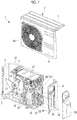
- Fig. 1 is an exploded perspective view of an outdoor unit according to an embodiment of the present invention.
- the outdoor unit 1 forms a multi-type air conditioning system by being connected to a plurality of indoor units, which are installed in a store, an office, a house, and the like, through refrigerant pipes.
- the outdoor unit 1 includes a base plate 2 (see also Fig. 6 ) that is positioned at a bottom portion of the outdoor unit 1 and is formed by, for example, a sheet metal press and a box-like housing 3 that is mounted on the base plate 2 and is made of, for example, sheet metal.
- the housing 3 is a combination of a front panel 4, a top panel 5, a left side panel (not shown), a right side panel 6, and a back panel (not shown).
- An air discharge outlet 4a is formed at the front panel 4, and air suction openings are formed at the left side panel and the back panel (not shown).
- a heat exchanger room 8 is installed one side (for example, left side) in a width direction and a machine room 9 is installed on the other side (for example, right side).
- the heat exchanger room 8 and the machine room 9 are partitioned by a partition wall 10.
- a heat exchanger 12, which is formed in a substantially L shape in plan view, is installed in the heat exchanger room 8.
- the heat exchanger 12 overlaps the air suction openings that are formed at the left side panel and the back panel of the housing 3.
- a fan blade 13 and a fan motor 14, which supplies cooling air to the heat exchanger 12, are supported by a fan bracket 15 and are installed in the heat exchanger room 8. Outside air is sucked into the heat exchanger room 8 from the air suction openings, which are formed at the back surface and left side surface of the housing 3, as cooling air by the rotation of the fan blade 13. After the cooling air exchanges heat with a refrigerant while passing through the heat exchanger 12, the cooling air is discharged from the air discharge outlet 4a that is formed at the front surface of the housing 3.
- a strainer 19 see Figs. 5 and 6
- an accumulator 20 and an electric box (controller) 21, including a refrigerant compressor (compressor) 18 compressing a refrigerant
- the outdoor unit 1 is a multi-type outdoor unit that compresses refrigerants of, for example, two indoor units by one refrigerant compressor 18, the right side panel 6, which forms the right side surface of the housing 3, is provided with two connection valves 25 and 26 and a highpressure refrigerant pipe and a low-pressure refrigerant pipe (not shown) to be connected to each indoor unit are connected to each of the connection valves 25 and 26.
- an expanded portion 30, which is formed of a part of the right side panel 6 expanded in the shape of a projection, is formed on the right side panel 6.
- a height H (see Fig. 6 ) of the expanded portion 30 is set to about 3 to 5 cm
- two upper and lower connection valve-installation portions 35 and 36 are formed on an expanded surface 31 that is the outer surface of the expanded portion 30 expanded to the outermost side
- the respective connection valves 25 and 26 are fastened and fixed to these two connection valve-installation portions 35 and 36 by bolts.
- the expanded portion 30 and the connection valves 25 and 26 are covered with a design cover 38, which is shown in Fig. 1 and molded with a resin, so that the appearance of the outdoor unit 1 is formed.
- the interior space of the housing 3 is enlarged by the internal volume of the expanded portion 30.
- at least one of the internal devices to be connected to the connection valves 25 and 26 is disposed in an interior space S of the expanded portion 30.
- a high-capacity strainer 19, which is to be connected to the connection valves 25 and 26, is disposed in the interior space S of the expanded portion 30 in this embodiment, but other internal devices may be disposed in the interior space S.
- an expanded bracket member 41 which is formed by bending a sheet metal material separate from the right side panel 6, is fitted to a vertically long rectangular opening portion 40, which is formed at the right side panel 6, from the inside, so that the expanded portion 30 is formed.
- the thickness of the expanded bracket member 41 is set to be larger than the thickness of the right side panel 6 so that the expanded bracket member 41 has strength.
- the thickness of the expanded bracket member 41 is set to be the same as the thickness of the base plate 2.
- two fastening bosses 42 are formed at the lower edge portion of the expanded bracket member 41, these fastening bosses 42 overlap the inside of a rising wall 2a formed around the base plate 2, and two screws 43 are fastened to the fastening bosses 42 through the rising wall 2a from the outside, so that the expanded bracket member 41 is firmly fixed to the base plate 2.
- the expanded bracket member 41 includes the above-mentioned expanded surface 31 that is positioned so as to be offset to the outside from the right side panel 6 of the housing 3 by the height H, and a pair of upper and lower rising surfaces 32 and 33 that extends toward the right side panel 6 from two opposite upper and lower sides of the expanded surface 31 and is connected to the rectangular opening portion 40.
- the rising surfaces 32 and 33 are formed so as to be bent at opening angles ⁇ 1 and ⁇ 2 (see Fig. 6 ) of about 90° to 135° with respect to the expanded surface 31.
- the opening angles ⁇ 1 and ⁇ 2 are set so that the expanded surface 31, the rising surface 32, and the rising surface 33 form a substantially trapezoidal shape in front view (see Fig. 6 ).
- these opening angles ⁇ 1 and ⁇ 2 are set to be closer to a right angle, the internal volume (space S) of the expanded portion 30 can be enlarged by an increase in the length of the expanded surface 31 in a vertical direction, that is, the area of the expanded surface 31.
- the opening angles ⁇ 1 and ⁇ 2 of the rising surfaces 32 and 33 are too close to a right angle, condensed water, which drips from the surfaces of the internal devices disposed in the expanded portion 30, flows on the upper surface of the lower rising surface 33 and may flow to the outside. Accordingly, the opening angles ⁇ 1 and 02 need to be set to be larger than a right angle to some extent.
- the effective area of the expanded surface 31 and the effective areas of the connection valve-installation portions 35 and 36 are reduced due to the inclination angles of the rising surfaces 32 and 33 in a case in which the height H of the expanded portion 30 is set to be too large, the height H of the expanded portion 30 needs to be properly selected.
- connection valve-installation portions 35 and 36 are embossed and formed so as to expand outward from the base plane of the expanded surface 31.
- a locking piece 32a which is to be locked to the upper side of the rectangular opening portion 40, is integrally formed at the tip portion of the upper rising surface 32 so as to be bent, and the two fastening bosses 42, which fix the expanded bracket member 41 to the base plate 2, are formed below the lower rising surface 33 as described above.
- overlapping margins 41a which overlap closing panels 45 and 46 to be described below, are provided at both edge portions of each of the surfaces 31, 32, and 33.
- a pair of closing panels 45 and 46 is bent so as to rise from two vertical sides, which face each other, of the rectangular opening portion 40 of the right side panel 6 at a right angle with respect to the surface direction of the right side panel 6.
- the pair of closing panels 45 and 46 faces each other in parallel to each other.
- the inner portions of the rectangular opening portion 40 are bent outward at a right angle without being cut off, so that the closing panels 45 and 46 are formed integrally with the right side panel 6.
- the shape of the contour of the outer periphery of each of these closing panels 45 and 46 in plan view follows the shape of the trapezoidal shape of the expanded bracket member 41.
- bent edge portions 45a and 46a which overlap the expanded surface 31 of the expanded bracket member 41 from the outside, are formed at the closing panels 45 and 46 of the right side panel 6 and, for example, a total of six fastening pieces 45b and 46b are formed at both upper and lower end portions and intermediate portions of the bent edge portions 45a and 46a.
- these six fastening pieces 45b and 46b overlap the expanded surface 31 and screws 48, which penetrate from the outside, are fastened to fastening bosses 31a (see Fig. 6 ) formed on the expanded surface 31 of the expanded bracket member 41, the expanded bracket member 41 is fixed to the right side panel 6 (closing panels 45 and 46) and the rectangular opening portion 40 is closed. As a result, the expanded portion 30 is formed.
- tongue-like locking protrusions 45c and 46c are formed at four fastening pieces 45b and 46b, which correspond to four corners of the expanded surface 31 of the expanded bracket member 41, among the six fastening pieces 45b and 46b that are formed at the closing panels 45 and 46 of the right side panel 6.
- These four locking protrusions 45c and 46c are engaged with slit hole-like locking holes 31b that are formed in four corners of the expanded surface 31. Accordingly, the expanded bracket member 41 is positioned.
- the locking hole 31b is formed as a horizontal slit hole in this embodiment, but may be formed as a vertical slit hole or may have the shape of a hole other than a slit hole.
- the outdoor unit 1 has the above-mentioned structure.
- the interior space of the housing 3 can be enlarged so that other internal devices can be disposed in the interior space S.
- the plurality of connection valves 25 and 26 are installed on the expanded surface 31 of the expanded portion 30 and internal devices (for example, the strainer 19) to be connected to the connection valves 25 and 26 are disposed in the enlarged interior space S of the expanded portion 30.
- the housing 3 can be shared between a single-type outdoor unit and a multi-type outdoor unit, so that the manufacturing costs of the outdoor unit 1 can be significantly reduced.
- the plurality of connection valves 25 and 26 can be installed on the expanded portion 30. Accordingly, in a case in which the expanded portion 30 on which the plurality of connection valves 25 and 26 can be installed as described above is provided on a housing 3 designed for a single-type outdoor unit, the housing 3 can be easily shared as a housing for a multi-type outdoor unit. In a case in which an expanded portion 30 of which the connection valve-installation portions 35 and 36 are replaced with one connection valve-installation portion is provided on a housing, the housing can also be used as a housing for a single-type outdoor unit.
- the expanded bracket member 41 is attached to the rectangular opening portion 40 formed at, for example, the right side panel 6 of the housing 3, so that the expanded portion 30 is formed.
- the expanded bracket member 41 is formed by bending a sheet metal material; and includes the expanded surface 31 on which the connection valves 25 and 26 are installed, and the pair of rising surfaces 32 and 33 that extends from two opposite sides of the expanded surface 31 and is connected to the rectangular opening portion 40. That is, the expanded bracket member 41 is formed by not drawing but bending.
- the degree of freedom in the shape of the expanded bracket member 41 is increased, the height H of the expanded portion 30 is set to be large to further enlarge the interior space of the housing 3, and the angles of the rising surfaces 32 and 33 with respect to the side surface of the housing 3 are set to steep angles to increase the area of the expanded surface 31. Accordingly, two or more connection valves 25 and 26 can be reasonably installed. Moreover, since the waste of materials and the reduction of yield, which occur during drawing, do not occur, material costs involved in the manufacture of the housing 3 can be reduced.
- the pair of closing panels 45 and 46 which closes the opening portions formed on the sides of the expanded bracket member 41, are bent so as to rise from two opposite sides of the rectangular opening portion 40, which are formed at the right side panel 6 of the housing 3, at a right angle. Accordingly, the pair of closing panels 45 and 46 is formed integrally with the right side panel 6. According to this structure, portions, which should have been cut off in the past in a case in which the rectangular opening portion 40 is to be formed at the side surface of the housing 3, can be used as the closing panels 45 and 46. For this reason, material costs involved in the manufacture of the housing 3 can be reduced.
- the fastening pieces 45b and 46b overlapping the surface of the expanded surface 31 of the expanded bracket member 41 are formed at the closing panels 45 and 46, and the locking protrusions 45c and 46c, which are to be engaged with the locking holes 31b formed in the expanded surface 31, are formed at the fastening pieces 45b and 46b.
- the locking protrusions 45c and 46c of the closing panels 45 and 46 are engaged with the locking holes 31b of the expanded surface 31, so that the closing panels 45 and 46 are fastened after being maintained in a state in which the closing panels 45 and 46 are pulled to the expanded surface 31. For this reason, since it is possible to prevent gaps from being formed between the expanded surface 31 (expanded bracket member 41) and the closing panels 45 and 46, it is possible to prevent the deterioration of appearance, the leakage of interior noise, and the like.
- the outdoor unit 1 of an air conditioning system of this embodiment it is possible to reduce the manufacturing costs of the outdoor unit 1 by reducing the size of the housing 3, sharing the housing 3 between a single-type outdoor unit and a multi-type outdoor unit, and reducing the material costs of the housing 3.
- the present invention is not limited to only the structure of the embodiment and can be appropriately modified or improved, and embodiments, which have been modified or improved in this way, are also included in the scope of the right of the present invention.
- the internal devices, which are received in the interior space S of the expanded portion 30, are not limited to the strainer 19, and other devices or only pipes may be received.
- the expanded portion 30 may be formed at the left side surface of the housing 3.
- examples in which the expanded portion 30 is formed at the front surface, the rear surface, and the upper surface of the housing 3 are also considered as modification examples.
- an expanded bracket member 41 formed by bending a sheet metal material is fixed to the right side panel 6 formed by bending a sheet metal material likewise, so that the expanded portion 30 is formed in this embodiment.
- the expanded portion 30 is not limited to this structure, and, for example, the expanded portion 30 may be molded with a resin or may be made of a combination of a resin and metal.
Landscapes
- Engineering & Computer Science (AREA)
- Chemical & Material Sciences (AREA)
- Combustion & Propulsion (AREA)
- Mechanical Engineering (AREA)
- General Engineering & Computer Science (AREA)
- Other Air-Conditioning Systems (AREA)
Abstract
Description
- The present invention relates to an outdoor unit of an air conditioning system.
- In a multi-type air conditioning system in which a plurality of indoor units are connected to one outdoor unit, connection valves (connection ports) corresponding to the number of indoor units are installed on one side surface of the outdoor unit. For this reason, the outdoor unit is increased in size. For the solution of the problem, in an outdoor unit disclosed in PTL 1, a platelike attachment member 22, which protrudes laterally, is attached to a
side surface 2a of anoutdoor unit body 2 and a plurality ofconnection ports Figs. 1 to 3 of PTL 1. According to this structure, since a space on theside surface 2a of theoutdoor unit body 2 can be efficiently used, an increase in the size of the outdoor unit in a planar shape can be considerably suppressed. - [PTL 1] Japanese Unexamined Patent Application Publication No.
11-230581 - However, strainers and various internal devices corresponding to the number of the indoor units are received in a housing of the outdoor unit of the multi-type air conditioning system in addition to the above-mentioned connection valves (connection ports). For this reason, there is a situation that the housing of a single-type outdoor unit is hard to be shared in a multi-type outdoor unit.
- The present invention has been made in consideration of the above-mentioned situation, and an object of the present invention is to provide an outdoor unit of an air conditioning system of which the manufacturing costs can be reduced by a reduction in the size of a housing, the sharing of the housing between a single-type outdoor unit and a multi-type outdoor unit, and a reduction in the material costs of the housing.
- The present invention employs the following means to achieve the object.
- That is, an outdoor unit of an air conditioning system according to the present invention includes: an expanded portion that is formed of a part, which is expanded in the shape of a projection, of a side surface of a housing in which a plurality of internal devices, such as a refrigerant compressor and a heat exchanger, are received; and a connection valve which is installed on an expanded surface of the expanded portion and to which a refrigerant pipe to be connected to an indoor unit is connected. At least one of the internal devices to be connected to the connection valve is disposed in an interior space of the expanded portion.
- According to the outdoor unit having the above-mentioned structure, at least one of the internal devices is disposed in the interior space of the expanded portion that is formed of a part, which is expanded in the shape of a projection, of the side surface of the housing. Accordingly, even though the housing is a housing for a single-type outdoor unit, a surplus space can be provided in the housing. Accordingly, other internal devices can be installed in this surplus space. For this reason, it is possible to reduce manufacturing costs by sharing the housing between a single-type outdoor unit and a multi-type outdoor unit.
- In the above-mentioned structure, the expanded portion may include a plurality of installation portions for the connection valve. In a case in which the expanded portion on which the plurality of connection valves can be installed as described above is attached to a housing designed for a single-type outdoor unit, the housing designed for a single-type outdoor unit can be easily shared as a housing for a multi-type outdoor unit.
- In the above-mentioned structure, the expanded portion may include: a rectangular opening portion that is formed at the side surface of the housing; an expanded bracket member that is formed by bending a sheet metal material separate from the side surface of the housing, is fitted to the rectangular opening portion, and includes the expanded surface which is positioned outside the side surface of the housing and on which the connection valve is installed and a pair of rising surfaces which extends from two opposite sides of the expanded surface and is connected to the rectangular opening portion; and a pair of closing panels that closes opening portions formed on sides of the expanded bracket member at which the rising surfaces are not formed.
- According to this structure, the expanded bracket member can be formed by not drawing but bending a sheet metal material. For this reason, the degree of freedom in the shape of the expanded bracket member can be increased, the expansion height of the expanded portion can be set to be large to enlarge the interior space, and the angles of the rising surfaces with respect to the side surface of the housing can be set to steep angles to increase the area of the top flat portion of the expanded portion. Moreover, since the waste of materials, which occurs during drawing, does not occur, the material costs of the housing can be reduced.
- In the above-mentioned structure, the closing panels may be integrated with the side surface of the housing, and may rise from two opposite sides of the rectangular opening portion. According to this structure, portions, which should have been cut off in the past in a case in which the rectangular opening portion is to be formed at the side surface of the housing, are bent from two opposite sides of the rectangular opening portion so as to rise and are used as the closing panels. For this reason, the material costs of the housing can be reduced.
- In the above-mentioned structure, fastening pieces, which overlap a surface of the expanded surface of the expanded bracket member, may be formed at the closing panels, and locking protrusions, which are to be engaged with locking holes formed in the expanded surface, may be formed at the fastening pieces.
- According to this structure, the locking protrusions of the closing panels (fastening pieces) are engaged with the locking holes of the expanded surface, so that the closing panels are fastened after being maintained in a state in which the both closing panels are pulled to the expanded surface. For this reason, it is possible to prevent the deterioration of appearance or the leakage of interior noise from gaps that is caused in a case in which gaps are formed between the expanded surface (expanded bracket member) and the closing panels.
- According to the outdoor unit of an air conditioning system of the present invention, as described above, it is possible to reduce the manufacturing costs of the outdoor unit by reducing the size of the housing, sharing the housing between a single-type outdoor unit and a multi-type outdoor unit, and reducing the material costs of the housing.
-
-
Fig. 1 is an exploded perspective view of an outdoor unit according to an embodiment of the present invention. -
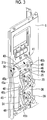
Fig. 2 is an exploded perspective view showing a right side panel of a housing and an expanded bracket member. -
Fig. 3 is a perspective view showing the right side panel of the housing and the expanded bracket member. -
Fig. 4 is a longitudinal sectional view taken along line IV-IV ofFig. 3 . -
Fig. 5 is a perspective view showing the expanded bracket member and internal devices disposed in the interior space of the expanded bracket member. -
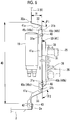
Fig. 6 is a longitudinal sectional view showing the right side panel, an expanded portion (expanded bracket member), and a strainer of the embodiment of the present invention. - An embodiment of the present invention will be described below with reference to the drawings.
-
Fig. 1 is an exploded perspective view of an outdoor unit according to an embodiment of the present invention. The outdoor unit 1 forms a multi-type air conditioning system by being connected to a plurality of indoor units, which are installed in a store, an office, a house, and the like, through refrigerant pipes. - The outdoor unit 1 includes a base plate 2 (see also
Fig. 6 ) that is positioned at a bottom portion of the outdoor unit 1 and is formed by, for example, a sheet metal press and a box-like housing 3 that is mounted on thebase plate 2 and is made of, for example, sheet metal. Thehousing 3 is a combination of afront panel 4, atop panel 5, a left side panel (not shown), aright side panel 6, and a back panel (not shown). Anair discharge outlet 4a is formed at thefront panel 4, and air suction openings are formed at the left side panel and the back panel (not shown). - In the
housing 3, aheat exchanger room 8 is installed one side (for example, left side) in a width direction and amachine room 9 is installed on the other side (for example, right side). Theheat exchanger room 8 and themachine room 9 are partitioned by apartition wall 10. Aheat exchanger 12, which is formed in a substantially L shape in plan view, is installed in theheat exchanger room 8. Theheat exchanger 12 overlaps the air suction openings that are formed at the left side panel and the back panel of thehousing 3. - Further, a
fan blade 13 and afan motor 14, which supplies cooling air to theheat exchanger 12, are supported by afan bracket 15 and are installed in theheat exchanger room 8. Outside air is sucked into theheat exchanger room 8 from the air suction openings, which are formed at the back surface and left side surface of thehousing 3, as cooling air by the rotation of thefan blade 13. After the cooling air exchanges heat with a refrigerant while passing through theheat exchanger 12, the cooling air is discharged from theair discharge outlet 4a that is formed at the front surface of thehousing 3. - Various devices, such as a strainer 19 (see
Figs. 5 and6 ), an accumulator 20, and an electric box (controller) 21, including a refrigerant compressor (compressor) 18 compressing a refrigerant are built in themachine room 9. Since the outdoor unit 1 is a multi-type outdoor unit that compresses refrigerants of, for example, two indoor units by onerefrigerant compressor 18, theright side panel 6, which forms the right side surface of thehousing 3, is provided with twoconnection valves connection valves - As shown in
Figs. 2 to 6 , an expandedportion 30, which is formed of a part of theright side panel 6 expanded in the shape of a projection, is formed on theright side panel 6. A height H (seeFig. 6 ) of the expandedportion 30 is set to about 3 to 5 cm, two upper and lower connection valve-installation portions surface 31 that is the outer surface of the expandedportion 30 expanded to the outermost side, and therespective connection valves installation portions portion 30 and theconnection valves design cover 38, which is shown inFig. 1 and molded with a resin, so that the appearance of the outdoor unit 1 is formed. - Since the expanded
portion 30 is provided, the interior space of thehousing 3 is enlarged by the internal volume of the expandedportion 30. As shown inFigs. 5 and6 , at least one of the internal devices to be connected to theconnection valves portion 30. A high-capacity strainer 19, which is to be connected to theconnection valves portion 30 in this embodiment, but other internal devices may be disposed in the interior space S. - As shown in
Figs. 2 and3 , an expandedbracket member 41, which is formed by bending a sheet metal material separate from theright side panel 6, is fitted to a vertically longrectangular opening portion 40, which is formed at theright side panel 6, from the inside, so that the expandedportion 30 is formed. The thickness of the expandedbracket member 41 is set to be larger than the thickness of theright side panel 6 so that the expandedbracket member 41 has strength. For example, the thickness of the expandedbracket member 41 is set to be the same as the thickness of thebase plate 2. - As shown in
Figs. 2 ,5 , and6 , twofastening bosses 42 are formed at the lower edge portion of the expandedbracket member 41, thesefastening bosses 42 overlap the inside of a risingwall 2a formed around thebase plate 2, and twoscrews 43 are fastened to thefastening bosses 42 through the risingwall 2a from the outside, so that the expandedbracket member 41 is firmly fixed to thebase plate 2. - The expanded
bracket member 41 includes the above-mentioned expandedsurface 31 that is positioned so as to be offset to the outside from theright side panel 6 of thehousing 3 by the height H, and a pair of upper and lower risingsurfaces right side panel 6 from two opposite upper and lower sides of the expandedsurface 31 and is connected to therectangular opening portion 40. The rising surfaces 32 and 33 are formed so as to be bent at opening angles θ1 and θ2 (seeFig. 6 ) of about 90° to 135° with respect to the expandedsurface 31. - In this embodiment, the opening angles θ1 and θ2 are set so that the expanded
surface 31, the risingsurface 32, and the risingsurface 33 form a substantially trapezoidal shape in front view (seeFig. 6 ). As these opening angles θ1 and θ2 are set to be closer to a right angle, the internal volume (space S) of the expandedportion 30 can be enlarged by an increase in the length of the expandedsurface 31 in a vertical direction, that is, the area of the expandedsurface 31. - In a case in which the opening angles θ1 and θ2 of the rising
surfaces portion 30, flows on the upper surface of the lower risingsurface 33 and may flow to the outside. Accordingly, the opening angles θ1 and 02 need to be set to be larger than a right angle to some extent. - Further, since the effective area of the expanded
surface 31 and the effective areas of the connection valve-installation portions surfaces portion 30 is set to be too large, the height H of the expandedportion 30 needs to be properly selected. - The connection valve-
installation portions surface 31. Alocking piece 32a, which is to be locked to the upper side of therectangular opening portion 40, is integrally formed at the tip portion of the upper risingsurface 32 so as to be bent, and the twofastening bosses 42, which fix the expandedbracket member 41 to thebase plate 2, are formed below the lower risingsurface 33 as described above. Further, overlappingmargins 41a, which overlap closingpanels surfaces - A pair of
closing panels rectangular opening portion 40 of theright side panel 6 at a right angle with respect to the surface direction of theright side panel 6. The pair ofclosing panels rectangular opening portion 40 is formed at theright side panel 6, the inner portions of therectangular opening portion 40 are bent outward at a right angle without being cut off, so that theclosing panels right side panel 6. The shape of the contour of the outer periphery of each of these closingpanels bracket member 41. - In a case in which the expanded
bracket member 41 is attached to therectangular opening portion 40 of theright side panel 6, opening portions formed on sides of the expandedbracket member 41 at which the risingsurfaces panels housing 3, is closed by oneclosing panel 45 and the opening portion, which faces the rear side of thehousing 3, is closed by theother closing panel 46. Since the overlappingmargins 41a, which are provided at each of thesurfaces bracket member 41, overlap theclosing panels Figs. 2 ,4 ,5 , and6 , gaps through which the inside of the expandedportion 30 is seen are hard to be formed between each of thesurfaces bracket member 41 and theclosing panels - As shown in
Figs. 2 to 4 ,bent edge portions surface 31 of the expandedbracket member 41 from the outside, are formed at theclosing panels right side panel 6 and, for example, a total of sixfastening pieces bent edge portions fastening pieces surface 31 and screws 48, which penetrate from the outside, are fastened tofastening bosses 31a (seeFig. 6 ) formed on the expandedsurface 31 of the expandedbracket member 41, the expandedbracket member 41 is fixed to the right side panel 6 (closingpanels 45 and 46) and therectangular opening portion 40 is closed. As a result, the expandedportion 30 is formed. - As shown in
Figs. 2 to 4 and6 , tongue-like locking protrusions fastening pieces surface 31 of the expandedbracket member 41, among the sixfastening pieces closing panels right side panel 6. These four lockingprotrusions surface 31. Accordingly, the expandedbracket member 41 is positioned. Thelocking hole 31b is formed as a horizontal slit hole in this embodiment, but may be formed as a vertical slit hole or may have the shape of a hole other than a slit hole. - The outdoor unit 1 has the above-mentioned structure.
- In the outdoor unit 1, an expanded
portion 30, which expands outward in the shape of a projection, is formed on theright side panel 6 that forms, for example, the right side surface of thehousing 3. For this reason, the interior space of thehousing 3 can be enlarged so that other internal devices can be disposed in the interior space S. In this embodiment, the plurality ofconnection valves surface 31 of the expandedportion 30 and internal devices (for example, the strainer 19) to be connected to theconnection valves portion 30. In this case, for example, even though a housing is ahousing 3 for a single-type outdoor unit, the interior space of thehousing 3 is effectively used so that the housing can be used for a multi-type outdoor unit. Accordingly, thehousing 3 can be shared between a single-type outdoor unit and a multi-type outdoor unit, so that the manufacturing costs of the outdoor unit 1 can be significantly reduced. - The plurality of
connection valves portion 30. Accordingly, in a case in which the expandedportion 30 on which the plurality ofconnection valves housing 3 designed for a single-type outdoor unit, thehousing 3 can be easily shared as a housing for a multi-type outdoor unit. In a case in which an expandedportion 30 of which the connection valve-installation portions - The expanded
bracket member 41 is attached to therectangular opening portion 40 formed at, for example, theright side panel 6 of thehousing 3, so that the expandedportion 30 is formed. The expandedbracket member 41 is formed by bending a sheet metal material; and includes the expandedsurface 31 on which theconnection valves surfaces surface 31 and is connected to therectangular opening portion 40. That is, the expandedbracket member 41 is formed by not drawing but bending. - For this reason, the degree of freedom in the shape of the expanded
bracket member 41 is increased, the height H of the expandedportion 30 is set to be large to further enlarge the interior space of thehousing 3, and the angles of the risingsurfaces housing 3 are set to steep angles to increase the area of the expandedsurface 31. Accordingly, two ormore connection valves housing 3 can be reduced. - Further, the pair of
closing panels bracket member 41, are bent so as to rise from two opposite sides of therectangular opening portion 40, which are formed at theright side panel 6 of thehousing 3, at a right angle. Accordingly, the pair ofclosing panels right side panel 6. According to this structure, portions, which should have been cut off in the past in a case in which therectangular opening portion 40 is to be formed at the side surface of thehousing 3, can be used as theclosing panels housing 3 can be reduced. - In addition, the
fastening pieces surface 31 of the expandedbracket member 41 are formed at theclosing panels protrusions holes 31b formed in the expandedsurface 31, are formed at thefastening pieces protrusions closing panels 45 and 46 (fastening pieces holes 31b of the expandedsurface 31, so that theclosing panels closing panels surface 31. For this reason, since it is possible to prevent gaps from being formed between the expanded surface 31 (expanded bracket member 41) and theclosing panels - According to the outdoor unit 1 of an air conditioning system of this embodiment, as described above, it is possible to reduce the manufacturing costs of the outdoor unit 1 by reducing the size of the
housing 3, sharing thehousing 3 between a single-type outdoor unit and a multi-type outdoor unit, and reducing the material costs of thehousing 3. - The present invention is not limited to only the structure of the embodiment and can be appropriately modified or improved, and embodiments, which have been modified or improved in this way, are also included in the scope of the right of the present invention.
- For example, the internal devices, which are received in the interior space S of the expanded
portion 30, are not limited to thestrainer 19, and other devices or only pipes may be received. Further, the expandedportion 30 may be formed at the left side surface of thehousing 3. Alternatively, examples in which the expandedportion 30 is formed at the front surface, the rear surface, and the upper surface of thehousing 3 are also considered as modification examples. Furthermore, an expandedbracket member 41 formed by bending a sheet metal material is fixed to theright side panel 6 formed by bending a sheet metal material likewise, so that the expandedportion 30 is formed in this embodiment. However, the expandedportion 30 is not limited to this structure, and, for example, the expandedportion 30 may be molded with a resin or may be made of a combination of a resin and metal. -
- 1: outdoor unit
- 3: housing
- 6: right side panel
- 12: heat exchanger
- 18: refrigerant compressor
- 19: strainer (internal devices)
- 25, 26: connection valve
- 30: expanded portion
- 31: expanded surface
- 31b: locking hole
- 32, 33: rising surface
- 35, 36: connection valve-installation portion
- 40: rectangular opening portion
- 41: expanded bracket member
- 45, 46: closing panel
- 45b, 46b: fastening piece
- 45c, 46c: locking protrusion
- S: interior space of expanded portion
Claims (5)
- An outdoor unit of an air conditioning system comprising:an expanded portion that is formed of a part, which is expanded in the shape of a projection, of a side surface of a housing in which a plurality of internal devices, such as a refrigerant compressor and a heat exchanger, are received; anda connection valve which is installed on an expanded surface of the expanded portion and to which a refrigerant pipe to be connected to an indoor unit is connected,wherein at least one of the internal devices to be connected to the connection valve is disposed in an interior space of the expanded portion.
- The outdoor unit of an air conditioning system according to claim 1,
wherein the expanded portion includes a plurality of installation portions for the connection valve. - The outdoor unit of an air conditioning system according to claim 1 or 2,
wherein the expanded portion includesa rectangular opening portion that is formed at the side surface of the housing,an expanded bracket member that is formed by bending a sheet metal material separate from the side surface of the housing, is fitted to the rectangular opening portion, and includes the expanded surface which is positioned outside the side surface of the housing and on which the connection valve is installed and a pair of rising surfaces which extends from two opposite sides of the expanded surface and is connected to the rectangular opening portion, anda pair of closing panels that closes opening portions formed on sides of the expanded bracket member at which the rising surfaces are not formed. - The outdoor unit of an air conditioning system according to claim 3,
wherein the closing panels are integrated with the side surface of the housing, and rise from two opposite sides of the rectangular opening portion. - The outdoor unit of an air conditioning system according to claim 4,
wherein fastening pieces, which overlap a surface of the expanded surface of the expanded bracket member, are formed at the closing panels, and
locking protrusions, which are to be engaged with locking holes formed in the expanded surface, are formed at the fastening pieces.
Applications Claiming Priority (2)
| Application Number | Priority Date | Filing Date | Title |
|---|---|---|---|
| JP2016075137A JP2017187204A (en) | 2016-04-04 | 2016-04-04 | Outdoor unit of air conditioning system |
| PCT/JP2017/013944 WO2017175717A1 (en) | 2016-04-04 | 2017-04-03 | Outdoor unit of air conditioning system |
Publications (2)
| Publication Number | Publication Date |
|---|---|
| EP3399249A1 true EP3399249A1 (en) | 2018-11-07 |
| EP3399249A4 EP3399249A4 (en) | 2019-02-27 |
Family
ID=60001173
Family Applications (1)
| Application Number | Title | Priority Date | Filing Date |
|---|---|---|---|
| EP17779095.3A Withdrawn EP3399249A4 (en) | 2016-04-04 | 2017-04-03 | Outdoor unit of air conditioning system |
Country Status (4)
| Country | Link |
|---|---|
| EP (1) | EP3399249A4 (en) |
| JP (1) | JP2017187204A (en) |
| AU (1) | AU2017246781B2 (en) |
| WO (1) | WO2017175717A1 (en) |
Family Cites Families (7)
| Publication number | Priority date | Publication date | Assignee | Title |
|---|---|---|---|---|
| JPH01153425U (en) * | 1988-04-13 | 1989-10-23 | ||
| JPH05133565A (en) * | 1991-11-15 | 1993-05-28 | Matsushita Electric Ind Co Ltd | Outdoor unit for air conditioner |
| JPH11230581A (en) | 1998-02-17 | 1999-08-27 | Daikin Ind Ltd | Outdoor machine of air-conditioner |
| JP4711790B2 (en) * | 2005-09-26 | 2011-06-29 | 三洋電機株式会社 | Air conditioner |
| IT1400970B1 (en) * | 2009-06-23 | 2013-07-05 | Sanyo Electric Co | AIR CONDITIONER WITH HEAT EXCHANGER WITH A PLURALITY OF HEAT EXCHANGES. |
| JP2011007371A (en) * | 2009-06-23 | 2011-01-13 | Sanyo Electric Co Ltd | Air conditioner |
| JP6099925B2 (en) * | 2012-10-04 | 2017-03-22 | 三菱重工業株式会社 | Air conditioner outdoor unit |
-
2016
- 2016-04-04 JP JP2016075137A patent/JP2017187204A/en not_active Withdrawn
-
2017
- 2017-04-03 AU AU2017246781A patent/AU2017246781B2/en not_active Expired - Fee Related
- 2017-04-03 WO PCT/JP2017/013944 patent/WO2017175717A1/en active Application Filing
- 2017-04-03 EP EP17779095.3A patent/EP3399249A4/en not_active Withdrawn
Also Published As
| Publication number | Publication date |
|---|---|
| AU2017246781B2 (en) | 2019-09-12 |
| WO2017175717A1 (en) | 2017-10-12 |
| JP2017187204A (en) | 2017-10-12 |
| EP3399249A4 (en) | 2019-02-27 |
| AU2017246781A1 (en) | 2018-06-28 |
Similar Documents
| Publication | Publication Date | Title |
|---|---|---|
| EP3240973B1 (en) | Outdoor unit of air conditioner | |
| EP3130866B1 (en) | Indoor unit of air conditioner | |
| EP2801763B1 (en) | Outdoor unit and refrigeration cycle device with outdoor unit | |
| US20140224457A1 (en) | Outdoor unit and refrigerating apparatus | |
| AU2014260970B2 (en) | Decorative panel and air-conditioner indoor unit provided with same | |
| EP3040631B1 (en) | Outdoor device of air conditioner | |
| EP3040629B1 (en) | Outdoor device for an air conditioner | |
| CN110770508B (en) | Outdoor unit of refrigerator | |
| US10274209B2 (en) | Air conditioner and indoor unit of the same | |
| JP2015210020A (en) | Outdoor unit of air conditioner | |
| EP3399249A1 (en) | Outdoor unit of air conditioning system | |
| WO2012160749A1 (en) | Outdoor unit for refrigeration device | |
| KR20170001705A (en) | An outdoor unit for a an air conditioner | |
| KR102073002B1 (en) | Air Conditioner | |
| EP3851758B1 (en) | Air conditioner | |
| KR20190141479A (en) | An outdoor unit for a an air conditioner | |
| WO2009133909A1 (en) | Indoor unit for air conditioner | |
| JP6827194B2 (en) | Outdoor refrigerator | |
| KR20160086141A (en) | Outdoor unit of air conditioiner | |
| CN217423585U (en) | Machine and air conditioner in air conditioning | |
| JP2013007561A (en) | Outdoor unit for refrigeration device | |
| CN214148169U (en) | Outdoor unit of air conditioner | |
| JP7438145B2 (en) | Outdoor unit of air conditioner | |
| WO2020129215A1 (en) | Indoor unit of air conditioning device, and air conditioning device | |
| CN109405066B (en) | Indoor unit of air conditioner |
Legal Events
| Date | Code | Title | Description |
|---|---|---|---|
| STAA | Information on the status of an ep patent application or granted ep patent |
Free format text: STATUS: THE INTERNATIONAL PUBLICATION HAS BEEN MADE |
|
| PUAI | Public reference made under article 153(3) epc to a published international application that has entered the european phase |
Free format text: ORIGINAL CODE: 0009012 |
|
| STAA | Information on the status of an ep patent application or granted ep patent |
Free format text: STATUS: REQUEST FOR EXAMINATION WAS MADE |
|
| 17P | Request for examination filed |
Effective date: 20180731 |
|
| AK | Designated contracting states |
Kind code of ref document: A1 Designated state(s): AL AT BE BG CH CY CZ DE DK EE ES FI FR GB GR HR HU IE IS IT LI LT LU LV MC MK MT NL NO PL PT RO RS SE SI SK SM TR |
|
| AX | Request for extension of the european patent |
Extension state: BA ME |
|
| A4 | Supplementary search report drawn up and despatched |
Effective date: 20190128 |
|
| RIC1 | Information provided on ipc code assigned before grant |
Ipc: F24F 1/0059 20190101ALI20190122BHEP Ipc: F24F 1/32 20110101AFI20190122BHEP Ipc: F24F 1/56 20110101ALI20190122BHEP Ipc: F24F 13/20 20060101ALI20190122BHEP |
|
| DAV | Request for validation of the european patent (deleted) | ||
| DAX | Request for extension of the european patent (deleted) | ||
| STAA | Information on the status of an ep patent application or granted ep patent |
Free format text: STATUS: THE APPLICATION HAS BEEN WITHDRAWN |
|
| 18W | Application withdrawn |
Effective date: 20191008 |