EP3399186B1 - Hydraulikvorrichtung - Google Patents
Hydraulikvorrichtung Download PDFInfo
- Publication number
- EP3399186B1 EP3399186B1 EP17169272.6A EP17169272A EP3399186B1 EP 3399186 B1 EP3399186 B1 EP 3399186B1 EP 17169272 A EP17169272 A EP 17169272A EP 3399186 B1 EP3399186 B1 EP 3399186B1
- Authority
- EP
- European Patent Office
- Prior art keywords
- piston
- piston pin
- head member
- hydraulic device
- flange
- Prior art date
- Legal status (The legal status is an assumption and is not a legal conclusion. Google has not performed a legal analysis and makes no representation as to the accuracy of the status listed.)
- Active
Links
- 230000006835 compression Effects 0.000 claims description 14
- 238000007906 compression Methods 0.000 claims description 14
- 125000006850 spacer group Chemical group 0.000 claims description 14
- 230000007704 transition Effects 0.000 claims description 6
- 230000001154 acute effect Effects 0.000 claims 1
- 238000007789 sealing Methods 0.000 description 6
- 230000002706 hydrostatic effect Effects 0.000 description 3
- 238000004519 manufacturing process Methods 0.000 description 3
- 230000008901 benefit Effects 0.000 description 2
- 230000000694 effects Effects 0.000 description 2
- 230000009286 beneficial effect Effects 0.000 description 1
- 239000012530 fluid Substances 0.000 description 1
- 238000005242 forging Methods 0.000 description 1
Images

Classifications
-
- F—MECHANICAL ENGINEERING; LIGHTING; HEATING; WEAPONS; BLASTING
- F04—POSITIVE - DISPLACEMENT MACHINES FOR LIQUIDS; PUMPS FOR LIQUIDS OR ELASTIC FLUIDS
- F04B—POSITIVE-DISPLACEMENT MACHINES FOR LIQUIDS; PUMPS
- F04B1/00—Multi-cylinder machines or pumps characterised by number or arrangement of cylinders
- F04B1/12—Multi-cylinder machines or pumps characterised by number or arrangement of cylinders having cylinder axes coaxial with, or parallel or inclined to, main shaft axis
- F04B1/20—Multi-cylinder machines or pumps characterised by number or arrangement of cylinders having cylinder axes coaxial with, or parallel or inclined to, main shaft axis having rotary cylinder block
- F04B1/2014—Details or component parts
- F04B1/2035—Cylinder barrels
-
- F—MECHANICAL ENGINEERING; LIGHTING; HEATING; WEAPONS; BLASTING
- F04—POSITIVE - DISPLACEMENT MACHINES FOR LIQUIDS; PUMPS FOR LIQUIDS OR ELASTIC FLUIDS
- F04B—POSITIVE-DISPLACEMENT MACHINES FOR LIQUIDS; PUMPS
- F04B1/00—Multi-cylinder machines or pumps characterised by number or arrangement of cylinders
- F04B1/12—Multi-cylinder machines or pumps characterised by number or arrangement of cylinders having cylinder axes coaxial with, or parallel or inclined to, main shaft axis
- F04B1/20—Multi-cylinder machines or pumps characterised by number or arrangement of cylinders having cylinder axes coaxial with, or parallel or inclined to, main shaft axis having rotary cylinder block
- F04B1/2014—Details or component parts
-
- F—MECHANICAL ENGINEERING; LIGHTING; HEATING; WEAPONS; BLASTING
- F04—POSITIVE - DISPLACEMENT MACHINES FOR LIQUIDS; PUMPS FOR LIQUIDS OR ELASTIC FLUIDS
- F04B—POSITIVE-DISPLACEMENT MACHINES FOR LIQUIDS; PUMPS
- F04B1/00—Multi-cylinder machines or pumps characterised by number or arrangement of cylinders
- F04B1/12—Multi-cylinder machines or pumps characterised by number or arrangement of cylinders having cylinder axes coaxial with, or parallel or inclined to, main shaft axis
- F04B1/20—Multi-cylinder machines or pumps characterised by number or arrangement of cylinders having cylinder axes coaxial with, or parallel or inclined to, main shaft axis having rotary cylinder block
- F04B1/2007—Arrangements for pressing the cylinder barrel against the valve plate, e.g. by fluid pressure
-
- F—MECHANICAL ENGINEERING; LIGHTING; HEATING; WEAPONS; BLASTING
- F04—POSITIVE - DISPLACEMENT MACHINES FOR LIQUIDS; PUMPS FOR LIQUIDS OR ELASTIC FLUIDS
- F04B—POSITIVE-DISPLACEMENT MACHINES FOR LIQUIDS; PUMPS
- F04B1/00—Multi-cylinder machines or pumps characterised by number or arrangement of cylinders
- F04B1/12—Multi-cylinder machines or pumps characterised by number or arrangement of cylinders having cylinder axes coaxial with, or parallel or inclined to, main shaft axis
- F04B1/20—Multi-cylinder machines or pumps characterised by number or arrangement of cylinders having cylinder axes coaxial with, or parallel or inclined to, main shaft axis having rotary cylinder block
- F04B1/22—Multi-cylinder machines or pumps characterised by number or arrangement of cylinders having cylinder axes coaxial with, or parallel or inclined to, main shaft axis having rotary cylinder block having two or more sets of cylinders or pistons
-
- F—MECHANICAL ENGINEERING; LIGHTING; HEATING; WEAPONS; BLASTING
- F04—POSITIVE - DISPLACEMENT MACHINES FOR LIQUIDS; PUMPS FOR LIQUIDS OR ELASTIC FLUIDS
- F04B—POSITIVE-DISPLACEMENT MACHINES FOR LIQUIDS; PUMPS
- F04B1/00—Multi-cylinder machines or pumps characterised by number or arrangement of cylinders
- F04B1/12—Multi-cylinder machines or pumps characterised by number or arrangement of cylinders having cylinder axes coaxial with, or parallel or inclined to, main shaft axis
- F04B1/26—Control
- F04B1/30—Control of machines or pumps with rotary cylinder blocks
- F04B1/32—Control of machines or pumps with rotary cylinder blocks by varying the relative positions of a swash plate and a cylinder block
- F04B1/324—Control of machines or pumps with rotary cylinder blocks by varying the relative positions of a swash plate and a cylinder block by changing the inclination of the swash plate
-
- F—MECHANICAL ENGINEERING; LIGHTING; HEATING; WEAPONS; BLASTING
- F04—POSITIVE - DISPLACEMENT MACHINES FOR LIQUIDS; PUMPS FOR LIQUIDS OR ELASTIC FLUIDS
- F04B—POSITIVE-DISPLACEMENT MACHINES FOR LIQUIDS; PUMPS
- F04B53/00—Component parts, details or accessories not provided for in, or of interest apart from, groups F04B1/00 - F04B23/00 or F04B39/00 - F04B47/00
- F04B53/14—Pistons, piston-rods or piston-rod connections
Definitions
- the present invention relates to a hydraulic device according to the preamble of claim 1.
- Such a hydraulic device is known from WO 2006/083163 .
- the shaft has a flange which extends perpendicularly to the first axis and the pistons are fixed to the flange at equiangular distance about the first axis of rotation.
- An equal number of cylindrical sleeves are supported by a barrel plate and rotate together with the barrel plate about the second axis of rotation which is angled with respect to the first axis of rotation.
- Each piston is sealed directly to the inner wall of the corresponding cylindrical sleeve, i.e. without using a piston ring.
- the cylindrical sleeve makes a combined translating and swivelling motion around the piston. Therefore, the circumferential outer side of each piston head is ball-shaped.
- the ball-shape creates a sealing line between the piston and the cylindrical sleeve which extends perpendicularly to the centre line of the cylindrical sleeve. Due to required accuracy of dimensions of the pistons, manufacturing of the pistons is rather expensive.
- An object of the invention is to provide a hydraulic device which can be manufactured in a low-cost manner.
- each of the pistons has a modular structure comprising a piston head member which forms the piston head, a piston pin which is fixed to the flange and to which the piston head member is mounted, and a spacer which is located at the outer side of the piston pin and sandwiched between the piston head member and the flange.
- piston head member which is a part that requires a tight tolerance, is only a part of the entire piston in assembled condition.
- the remainder of the piston parts requires less tight tolerances such that the total manufacturing costs of the hydraulic device can be minimized.
- the piston head member may be manufactured by means of forging or stamping, for example.
- the spacer supports the piston head member with respect to the flange and may be clamped between the piston head member and the flange upon mounting the piston parts to the flange.
- play is present between the piston pin and the spacer. This means that a torque and/or a lateral force onto the piston can be absorbed by the flange rather than the piston pin, since under operating conditions the spacer is pressed against the flange by hydrostatic pressure in the compression chamber.
- the spacer is a bush, which surrounds the piston pin.
- the bush may have a concentrical and cylindrical inner and outer side. Such a bush can be manufactured by cutting pieces from a pipe at relatively low cost.
- the piston head member may have a central through-hole through which the piston pin extends.
- the piston head member may be fixed to the piston pin in axial direction of the piston pin through a press fitting between a surrounding wall of the central through-hole and an outer surface portion of the piston pin.
- the piston pin may partly extend beyond the piston head member as seen from the flange in order to minimize dead volume in the compression chamber if the extension protrudes in an oil discharge channel of the sleeve in top dead centre of the piston, for example. This has an advantageous effect on noise emission and hydraulic efficiency of the hydraulic device.
- the piston head member comprises a circular recess around a centre line of the piston pin at a side of the piston head member facing away from the flange.
- the piston head member has a circumferential wall including the ball-shaped circumferential outer side and an opposite inner side which borders the recess.
- the resulting circumferential wall has the following effect under operating conditions. Due to internal pressure in the compression chamber the cylindrical sleeve deforms in radial direction under operating conditions.
- the recess in the piston head member forms part of the compression chamber and serves to deform the piston head member at the sealing line such that expansion of the piston head member follows the sleeve expansion. Consequently, leakage flow between the piston and the cylindrical sleeve at the sealing line is minimized.
- the piston pin has a piston pin shank which is fixed to the flange and extends through the through-hole and a piston pin head, wherein the piston head member is sandwiched between the piston pin head and the spacer. Due to the presence of the piston pin head which has a larger diameter than the piston pin shank, axial fixing of the piston head member is relatively simple between the spacer and the piston pin head.
- a concave transition zone is present between the piston pin head and the piston pin shank, wherein the piston pin head and the piston head member contact each other within the transition zone, since this provides a more or less automatic centring position of the piston head member with respect to the piston pin.
- the piston head member is cup-shaped including a circumferential wall which has an inner side opposite to said ball-shaped circumferential outer side, which wall surrounds a cavity in which the piston pin head is located such that a circumferential outer side of the piston pin head faces the inner side of the circumferential wall of the piston head member.
- the cup-shaped piston head member provides a cavity which accommodates the piston pin head such that the height of the piston head member and the piston pin head together in longitudinal direction of the piston pin can be limited.
- a slot-shaped cavity is present between the inner side of the circumferential wall and the circumferential outer side of the piston pin head because of the reasons as described hereinbefore in relation to another embodiment: due to internal pressure in the compression chamber the cylindrical sleeve deforms in radial direction under operating conditions.
- the slot-shaped cavity in the piston head member forms part of the compression chamber and serves to deform the piston head member at the sealing line such that expansion of the piston head member follows the sleeve expansion. Consequently, leakage flow between the piston and the sleeve at the sealing line is minimized.
- the outer side of the piston pin head and the inner side of the circumferential wall of the piston head member may be parallel in circumferential direction.
- the piston pin head may partly extend beyond the piston head member as seen from the flange.
- a contact area between the spacer and the flange should be relatively large, for example larger than the cross-sectional area of the piston pin at the flange.
- the ratio may even be larger than two.
- Fig. 1 shows internal parts of a hydraulic device 1, such as a pump or hydromotor, which are fitted into a housing 27 in a known manner.
- the hydraulic device 1 is provided with a shaft 2 which is supported by bearings 3 at both sides of the housing 27 and which is rotatable about a first axis of rotation 4.
- the housing 27 is provided on the one side with an opening with a shaft seal 5 in a known manner, as a result of which the end of the shaft 2, which is provided with a toothed shaft end 6, protrudes from the housing 27.
- a motor can be coupled to the toothed shaft end 6 if the hydraulic device 1 is a pump, and a driven tool can be coupled thereto if the hydraulic device 1 is a motor.
- the hydraulic device 1 comprises face plates 7 which are mounted inside the housing 27 at a distance from each other.
- the face plates 7 have a fixed position with respect to the housing 27 in rotational direction thereof.
- the shaft 2 extends through central through-holes in the face plates 7.
- the shaft 2 is provided with a flange 8 which extends perpendicularly to the first axis of rotation 4.
- a plurality of pistons 9 are fixed at both sides of the flange 8 at equiangular distance about the first axis of rotation 4, in this case fourteen pistons 9 on either side.
- Each of the pistons 9 has a modular structure which will be explained hereinafter.
- the pistons 9 have centre lines which extend parallel to the first axis of rotation 4.
- the planes of the face plates 7 are angled with respect to each other and with respect to the plane of the flange 8 in the embodiment as shown in Fig. 1 .
- Each of the pistons 9 cooperates with a cylindrical sleeve 10 to form a compression chamber 11 of variable volume.
- the hydraulic device 1 as shown in Fig. 1 has 28 compression chambers 11.
- the cylindrical sleeve 10 comprises a sleeve bottom 12 and a sleeve jacket 13.
- Each piston 9 is sealed directly to the inner wall of the sleeve jacket 13 through a piston head which is formed by a piston head member 14.
- the piston head member 14 is a part of the modular piston 9 and has a ball-shaped circumferential outer side.
- Fig. 2 shows the piston 9 including the piston head member 14 on a larger scale.
- each cylindrical sleeve 10 makes a combined translating and swivelling motion around the cooperating piston 9. Therefore, the outer side of each piston head member 14 is ball-shaped.
- the ball-shape creates a sealing line between the piston 9 and the cylindrical sleeve 10 which extends perpendicularly to the centre line of the cooperating cylindrical sleeve 10.
- the diameter of each piston 9 near the flange 8 is smaller than at the piston head member 14 in order to allow the relative motion of the cooperating cylindrical sleeves 10 about the pistons 9.
- the sides of the respective barrel plates 15 which are directed away from the flange 8 are supported by respective supporting surfaces of the face plates 7. Due to the inclined orientation of the face plates 7 with respect to the flange 8 the barrel plates 15 pivot about the ball hinges 16 during rotation with the shaft 2.
- the angle between the first axis of rotation and the respective second axes of rotation is approximately nine degrees in practice, but may be smaller or larger.
- the barrel plates 15 are pressed against the respective face plates 7 by means of springs 18 which are mounted in holes in the shaft 2.
- the compression chambers 11 communicate via a central through-hole in the respective sleeve bottoms 12 with cooperating passages 19 in the barrel plates 15.
- the passages 19 in the barrel plates 15 communicate via passages in the face plates 7 with a high-pressure port and a low-pressure port in the housing 27.
- Fig. 1 shows that each piston 9 is fixed to the flange 8 by means of a piston pin 20 which is pressed into a flange hole 21.
- Fig. 2 shows the press fitting for one piston 9.
- the flange 8 is provided with 28 flange holes 21, such that the pistons 9 on either side of the flange 8 alternately move into the top dead centre and bottom dead centre, which refers to the position where the volume of the compression chambers 11 is at its minimum and maximum, respectively. Consequently, in circumferential direction of the flange 8 adjacent flange holes 21 receive pistons 9 on either side of the flange 8.
- Fig. 2 shows one piston 9 of an embodiment of the hydraulic device 1.
- the piston head member 14 is cup-shaped and has a circumferential wall which has an inner side opposite to its ball-shaped outer side.
- the piston pin 20 has a piston pin head 22 and a piston pin shank 23.
- the diameter of the piston pin head 22 is larger than that of the piston pin shank 23.
- the piston pin shank 23 extends through a central through-hole 24 of the piston head member 14 and an end portion of the piston pin shank 23 is clamped in the flange hole 21.
- the modular piston 9 also comprises a spacer in the form of bush 26 which surrounds the piston pin shank 23 and is sandwiched between the piston head member 14 and the flange 8.
- the bush 26 has concentrical and cylindrical inner and outer surfaces. Furthermore, play is present between the piston pin shank 23 and the bush 26.
- the piston head member 14 is fixed to the piston pin 20 in axial direction of the piston pin 20 through a clamp connection between the piston pin head 14 and the bush 26. More specifically, the piston pin 20 is provided with a concave transition zone between the piston pin head 22 and the piston pin shank 23, whereas the clamp connection is located within the transition zone where a surrounding edge of the central through hole 24 of the piston head member 14 contacts the piston pin 20. Outside this contact location the piston pin 20 is free from the piston head member 14.
- the circumferential wall of the piston head member 14 surrounds a cavity in which a part of the piston pin head 22 is located.
- the diameter of the inner side of the circumferential wall is larger than the diameter of the piston pin head 22. Consequently, a slot-shaped cavity 25 is present between the inner side of the circumferential wall and the outer side of the piston pin head 22.
- the outer side of the piston pin head and the inner side of the circumferential wall of the piston head member 14 are parallel in circumferential direction. Furthermore, the piston pin head 22 partly extends beyond the piston head member 14 as seen from the flange 8.
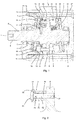
- Fig. 3 shows one modular piston 9 of an alternative embodiment of the hydraulic device 1.
- the piston pin 20 does not have a wide piston pin head, but it has a constant diameter along its longitudinal direction.
- the piston head member 14 is fixed to the piston pin 20 in axial direction of the piston pin 20 through a press fitting between a circumferential surface of the central through-hole 24 and an outer surface portion of the piston pin 20.
- the piston head member 14 is mounted onto the piston pin 20 such that the piston pin 20 partly extends beyond the piston head member 14 as seen from the flange 8.
- the piston head member 14 comprises a circular recess 28 around the centre line of the piston pin 20 at a side of the piston head member 14 facing away from the flange.
- the recess 28 is comparable to the slot-shaped cavity 25 of the embodiment as shown in Fig. 2 .
- the recess 28 is open in a direction directed from the flange 8 towards the piston head member 14.
- the modular piston 9 of the embodiment as shown in Fig. 3 also comprises a bush 26 which is sandwiched between the piston head member 14 and the flange 8.
- the bush 26 Upon assembly of the piston 9 of the embodiments as shown in Figs. 2 and 3 the bush 26 will be clamped between the piston head member 14 and the flange 8.
- the clamping force may be relatively small since a large clamping force will automatically be exerted by hydrostatic pressure in the compression chamber 11 under operating conditions of the hydraulic device 1.
- the hydrostatic pressure appears to press the bush 26 against the flange 8 up to a high level such that a transverse force resulting from the hydraulic pressure onto the piston 9 due to the angled position of the sleeve 10 with respect to the piston 9 is transferred via a contact area between the bush 26 and the flange 8. Consequently, a torque on the piston pin 23 can be minimized or even eliminated.
- the contact area should be relatively large, for example larger than the cross-sectional area of the corresponding flange hole 21.
- the outer diameter of the bush 26 may be at least 40% larger than its inner diameter.
Landscapes
- Engineering & Computer Science (AREA)
- Mechanical Engineering (AREA)
- General Engineering & Computer Science (AREA)
- Physics & Mathematics (AREA)
- Fluid Mechanics (AREA)
- Reciprocating Pumps (AREA)
- Pistons, Piston Rings, And Cylinders (AREA)
Claims (15)
- Hydraulikvorrichtung (1) mit einem Gehäuse (27), einer im Gehäuse (27) montierten und um eine erste Drehachse (4) drehbaren Welle (2), wobei die Welle (2) einen sich senkrecht zur ersten Achse (4) erstreckenden Flansch (8) aufweist, mehreren Kolben (9), die in gleichen Winkelabständen um die erste Drehachse (4) am Flansch (8) befestigt sind, und mehreren zylinderförmigen Hülsen (10), die mit dem Kolben (9) zusammenwirken, um jeweilige Kompressionskammern (11) mit variablem Volumen zu bilden, wobei die Hülsen (10) um eine zweite Drehachse drehbar sind, die die erste Drehachse (4) unter einem spitzen Winkel schneidet, so dass bei einer Drehbewegung der Welle (2) sich die Volumina der Kompressionskammern (11) ändern, und wobei jeder Kolben (9) einen Kolbenkopf (14) mit einer kugelförmigen Umfangsaußenseite aufweist,dadurch gekennzeichnet, dassjeder der Kolben (9) eine modulare Struktur hat, die ein Kolbenkopfelement (14), das den Kolbenkopf bildet, einen Kolbenbolzen (20), der am Flansch (8) befestigt ist und an dem der Kolbenkopf (20) montiert ist, und ein Abstandselement (26) aufweist, das an der Außenseite des Kolbenbolzens (20) angeordnet und zwischen dem Kolbenkopfelement (14) und dem Flansch (8) sandwichartig angeordnet ist.
- Hydraulikvorrichtung (1) nach Anspruch 1, wobei zwischen dem Kolbenbolzen (20) und dem Abstandselement (26) Spiel vorhanden ist.
- Hydraulikvorrichtung (1) nach Anspruch 1 oder 2, wobei das Abstandselement eine Buchse (26) ist, die den Kolbenbolzen (20) umgibt.
- Hydraulikvorrichtung (1) nach Anspruch 4, wobei die Buchse (26) eine konzentrische und zylinderförmige Innen- und Außenseite aufweist.
- Hydraulikvorrichtung (1) nach einem der vorangehenden Ansprüche, wobei das Kolbenkopfelement (14) ein mittiges Durchgangsloch (24) aufweist, durch das sich der Kolbenbolzen (20) erstreckt.
- Hydraulikvorrichtung (1) nach Anspruch 5, wobei das Kolbenkopfelement (14) am Kolbenbolzen (20) in einer axialen Richtung des Kolbenbolzens (20) durch eine Presspassung zwischen einer umgebenden Wand des mittigen Durchgangslochs (24) und einem Außenflächenabschnitt des Kolbenbolzens (20) befestigt ist.
- Hydraulikvorrichtung (1) nach Anspruch 5 oder 6, wobei der Kolbenbolzen (20) sich vom Flansch (8) aus betrachtet teilweise über das Kolbenkopfelement (14) hinaus erstreckt.
- Hydraulikvorrichtung (1) nach einem der vorangehenden Ansprüche, wobei das Kolbenkopfelement (14) eine kreisförmige Vertiefung (23) um eine Mittellinie des Kolbenbolzens (20) an einer dem Flansch (8) abgewandten Seite des Kolbenkopfelements (14) aufweist.
- Hydraulikvorrichtung (1) nach Anspruch 5, wobei der Kolbenbolzen (20) einen Kolbenbolzenschaft (23), der am Flansch (8) befestigt ist und sich durch das Durchgangsloch (24) erstreckt, und einen Kolbenbolzenkopf (22) aufweist, wobei das Kolbenkopfelement (14) zwischen dem Kolbenbolzenkopf (22) und dem Abstandselement (26) sandwichartig angeordnet ist.
- Hydraulikvorrichtung (1) nach Anspruch 9, wobei zwischen dem Kolbenbolzenkopf (22) und dem Kolbenbolzenschaft (23) ein konkaver Übergangsbereich vorhanden ist, wobei der Kolbenbolzenkopf (22) und das Kolbenkopfelement (14) sich innerhalb des Übergangsbereichs gegenseitig kontaktieren.
- Hydraulikvorrichtung (1) nach Anspruch 9 oder 10, wobei das Kolbenkopfelement (14) becherförmig ausgebildet ist und eine Umfangswand aufweist, die eine der kugelförmigen Umfangsaußenseite gegenüberliegende Innenseite aufweist, wobei die Wand einen Hohlraum umgibt, in dem sich der Kolbenbolzenkopf (22) befindet, so dass eine Umfangsaußenseite des Kolbenbolzenkopfs (22) der Innenseite der Umfangswand des Kolbenkopfelements (14) zugewandt ist.
- Hydraulikvorrichtung (1) nach Anspruch 11, wobei zwischen der Innenseite der Umfangswand des Kolbenkopfelements (14) und der Umfangsaußenseite des Kolbenbolzenkopfs (22) ein schlitzförmiger Hohlraum (25) vorhanden ist.
- Hydraulikvorrichtung (1) nach Anspruch 12, wobei die Außenseite des Kolbenbolzenkopfs (22) und die Innenseite der Umfangswand des Kolbenkopfelements (14) sich in Umfangsrichtung parallel erstrecken.
- Hydraulikvorrichtung (1) nach einem der Ansprüche 9 bis 13, wobei sich der Kolbenbolzenkopf (22) vom Flansch (8) aus betrachtet teilweise über das Kolbenkopfelement (14) hinaus erstreckt.
- Hydraulikvorrichtung (1) nach einem der vorangehenden Ansprüche, wobei ein Endabschnitt des Kolbenbolzens (20) im Flansch (8) festgeklemmt ist.
Priority Applications (5)
| Application Number | Priority Date | Filing Date | Title |
|---|---|---|---|
| EP17169272.6A EP3399186B1 (de) | 2017-05-03 | 2017-05-03 | Hydraulikvorrichtung |
| CN201880026215.7A CN110573731B (zh) | 2017-05-03 | 2018-05-02 | 一种液压装置 |
| PCT/EP2018/061117 WO2018202665A1 (en) | 2017-05-03 | 2018-05-02 | A hydraulic device |
| US16/609,974 US10961990B2 (en) | 2017-05-03 | 2018-05-02 | Hydraulic device |
| JP2019559355A JP7228249B2 (ja) | 2017-05-03 | 2018-05-02 | 油圧装置 |
Applications Claiming Priority (1)
| Application Number | Priority Date | Filing Date | Title |
|---|---|---|---|
| EP17169272.6A EP3399186B1 (de) | 2017-05-03 | 2017-05-03 | Hydraulikvorrichtung |
Publications (2)
| Publication Number | Publication Date |
|---|---|
| EP3399186A1 EP3399186A1 (de) | 2018-11-07 |
| EP3399186B1 true EP3399186B1 (de) | 2019-10-16 |
Family
ID=58669668
Family Applications (1)
| Application Number | Title | Priority Date | Filing Date |
|---|---|---|---|
| EP17169272.6A Active EP3399186B1 (de) | 2017-05-03 | 2017-05-03 | Hydraulikvorrichtung |
Country Status (5)
| Country | Link |
|---|---|
| US (1) | US10961990B2 (de) |
| EP (1) | EP3399186B1 (de) |
| JP (1) | JP7228249B2 (de) |
| CN (1) | CN110573731B (de) |
| WO (1) | WO2018202665A1 (de) |
Families Citing this family (1)
| Publication number | Priority date | Publication date | Assignee | Title |
|---|---|---|---|---|
| EP3477102B1 (de) * | 2017-10-25 | 2020-12-16 | Innas B.V. | Hydraulische vorrichtung |
Family Cites Families (23)
| Publication number | Priority date | Publication date | Assignee | Title |
|---|---|---|---|---|
| US3057668A (en) * | 1960-03-14 | 1962-10-09 | Stewart Warner Corp | Piston construction |
| JPS5517234B2 (de) * | 1973-09-20 | 1980-05-09 | ||
| US4363294A (en) * | 1978-05-25 | 1982-12-14 | Searle Russell J | Piston and cylinder machines |
| US6152014A (en) * | 1989-03-17 | 2000-11-28 | Willimczik; Wolfhart | Rotary piston machines |
| US5249506A (en) * | 1990-03-15 | 1993-10-05 | Wolfhart Willimczik | Rotary piston machines with a wear-resistant driving mechanism |
| US5564327A (en) * | 1992-04-22 | 1996-10-15 | Sims; James O. | Piston/piston rod assembly |
| US5304043A (en) * | 1992-09-29 | 1994-04-19 | Avmed Compressor Corporation | Multiple axis rotary compressor |
| SK41195A3 (en) * | 1992-10-30 | 1995-10-11 | Felice Pecorari | Volumetric fluid machine |
| US5794514A (en) * | 1995-01-19 | 1998-08-18 | S.A.I. Societa' Apparecchiature Idrauliche S.P.A. | Volumetric machine with curved liners |
| AT408898B (de) * | 1998-04-27 | 2002-03-25 | Joerg Thurner | Axialkolbenverstellmaschine |
| US20060012881A1 (en) * | 2000-05-25 | 2006-01-19 | Atomic Telecom | Atomic layer controlled optical filter design for next generation dense wavelength division multiplexer |
| NL1020932C2 (nl) | 2002-01-12 | 2003-07-15 | Innas Bv | Hydraulische inrichting. |
| WO2004055369A1 (de) * | 2002-12-18 | 2004-07-01 | Bosch Rexroth Ag | Axialkolbenmaschine |
| US7014429B2 (en) * | 2003-03-06 | 2006-03-21 | The United States Of America As Represented By The Administrator Of The U.S. Environmental Protection Agency | High-efficiency, large angle, variable displacement hydraulic pump/motor |
| NL1027657C2 (nl) | 2004-12-06 | 2006-06-07 | Innas Bv | Hydraulische inrichting. |
| CN100485164C (zh) * | 2006-12-29 | 2009-05-06 | 郭有祥 | 陀螺轮转式引擎 |
| DE102007011441A1 (de) * | 2007-03-08 | 2008-09-11 | Robert Bosch Gmbh | Axialkolbenmaschine |
| US20100107866A1 (en) | 2008-11-04 | 2010-05-06 | Caterpillar Inc. | Three speed floating cup hydraulic motor |
| NL2005504C2 (nl) * | 2010-10-12 | 2012-04-16 | Innas Bv | Hydraulische inrichting met een spiegelplaat. |
| JP6055987B2 (ja) * | 2013-04-10 | 2017-01-11 | 株式会社 神崎高級工機製作所 | 可動斜板式油圧装置 |
| US9890773B2 (en) * | 2014-06-11 | 2018-02-13 | Mat Industries, Llc | Wobble piston having angled compression ring and spherical piston cap |
| WO2016071752A1 (en) * | 2014-11-08 | 2016-05-12 | Money S.R.L. | Hydraulic machine with improved oscillating axial cylinders |
| EP3246565B1 (de) | 2016-05-19 | 2019-09-18 | Innas B.V. | Hydraulikvorrichtung |
-
2017
- 2017-05-03 EP EP17169272.6A patent/EP3399186B1/de active Active
-
2018
- 2018-05-02 CN CN201880026215.7A patent/CN110573731B/zh active Active
- 2018-05-02 WO PCT/EP2018/061117 patent/WO2018202665A1/en active Application Filing
- 2018-05-02 US US16/609,974 patent/US10961990B2/en active Active
- 2018-05-02 JP JP2019559355A patent/JP7228249B2/ja active Active
Non-Patent Citations (1)
| Title |
|---|
| None * |
Also Published As
| Publication number | Publication date |
|---|---|
| JP7228249B2 (ja) | 2023-02-24 |
| JP2020518754A (ja) | 2020-06-25 |
| WO2018202665A1 (en) | 2018-11-08 |
| US20200063722A1 (en) | 2020-02-27 |
| CN110573731A (zh) | 2019-12-13 |
| US10961990B2 (en) | 2021-03-30 |
| CN110573731B (zh) | 2021-08-17 |
| EP3399186A1 (de) | 2018-11-07 |
Similar Documents
| Publication | Publication Date | Title |
|---|---|---|
| US7967574B2 (en) | Variable pump or hydraulic motor | |
| JP5027303B2 (ja) | 調節手段を有する斜板構造の軸流ピストン装置 | |
| US20060120881A1 (en) | Axial piston engine | |
| US11067067B2 (en) | Hydraulic device | |
| CN110067724B (zh) | 一种滑盘支承式通轴柱塞泵或马达 | |
| US10914172B2 (en) | Hydraulic device | |
| JP3386463B2 (ja) | シールドバーレルプレートを備えたアキシャルピストン流体移送装置 | |
| KR970001131B1 (ko) | 경사판식 압축기에 있어서 회전축 지지구조 | |
| US6698199B2 (en) | Swash plate type hydraulic drive transmission and hydrostatic type continuously variable transmission | |
| EP2045465A1 (de) | Verdichter | |
| US10961990B2 (en) | Hydraulic device | |
| US10533544B2 (en) | Swash plate type liquid-pressure rotating device and method of manufacturing same | |
| US7575420B2 (en) | Vane pump | |
| US5085127A (en) | Cavitation resistant hydraulic cylinder block porting faces | |
| KR20080009114A (ko) | 균형 플레이트-셔틀볼 | |
| US4426914A (en) | Axial piston pump | |
| US3636820A (en) | Hydraulic apparatus | |
| US20190032645A1 (en) | Variable displacement swash plate type piston pump | |
| JPH07158744A (ja) | 面シール装置 | |
| CN113874622A (zh) | 密封结构以及液压旋转机 | |
| US20100028169A1 (en) | Hydraulic device having an alignment component | |
| JP3962511B2 (ja) | 多連型ポンプ構造 | |
| CN116104723A (zh) | 一种双列柱塞泵 | |
| CN118188378A (zh) | 一种无需柱塞环的主轴等速驱动浮动斜盘式轴向柱塞泵 | |
| JPS63227964A (ja) | ラジアルピストン形油圧装置 |
Legal Events
| Date | Code | Title | Description |
|---|---|---|---|
| PUAI | Public reference made under article 153(3) epc to a published international application that has entered the european phase |
Free format text: ORIGINAL CODE: 0009012 |
|
| STAA | Information on the status of an ep patent application or granted ep patent |
Free format text: STATUS: THE APPLICATION HAS BEEN PUBLISHED |
|
| AK | Designated contracting states |
Kind code of ref document: A1 Designated state(s): AL AT BE BG CH CY CZ DE DK EE ES FI FR GB GR HR HU IE IS IT LI LT LU LV MC MK MT NL NO PL PT RO RS SE SI SK SM TR |
|
| AX | Request for extension of the european patent |
Extension state: BA ME |
|
| STAA | Information on the status of an ep patent application or granted ep patent |
Free format text: STATUS: REQUEST FOR EXAMINATION WAS MADE |
|
| 17P | Request for examination filed |
Effective date: 20190411 |
|
| RBV | Designated contracting states (corrected) |
Designated state(s): AL AT BE BG CH CY CZ DE DK EE ES FI FR GB GR HR HU IE IS IT LI LT LU LV MC MK MT NL NO PL PT RO RS SE SI SK SM TR |
|
| GRAP | Despatch of communication of intention to grant a patent |
Free format text: ORIGINAL CODE: EPIDOSNIGR1 |
|
| STAA | Information on the status of an ep patent application or granted ep patent |
Free format text: STATUS: GRANT OF PATENT IS INTENDED |
|
| INTG | Intention to grant announced |
Effective date: 20190603 |
|
| GRAS | Grant fee paid |
Free format text: ORIGINAL CODE: EPIDOSNIGR3 |
|
| GRAA | (expected) grant |
Free format text: ORIGINAL CODE: 0009210 |
|
| STAA | Information on the status of an ep patent application or granted ep patent |
Free format text: STATUS: THE PATENT HAS BEEN GRANTED |
|
| AK | Designated contracting states |
Kind code of ref document: B1 Designated state(s): AL AT BE BG CH CY CZ DE DK EE ES FI FR GB GR HR HU IE IS IT LI LT LU LV MC MK MT NL NO PL PT RO RS SE SI SK SM TR |
|
| REG | Reference to a national code |
Ref country code: GB Ref legal event code: FG4D |
|
| REG | Reference to a national code |
Ref country code: CH Ref legal event code: EP |
|
| REG | Reference to a national code |
Ref country code: DE Ref legal event code: R096 Ref document number: 602017007775 Country of ref document: DE |
|
| REG | Reference to a national code |
Ref country code: NL Ref legal event code: FP Ref country code: IE Ref legal event code: FG4D |
|
| REG | Reference to a national code |
Ref country code: AT Ref legal event code: REF Ref document number: 1191526 Country of ref document: AT Kind code of ref document: T Effective date: 20191115 |
|
| REG | Reference to a national code |
Ref country code: SE Ref legal event code: TRGR |
|
| REG | Reference to a national code |
Ref country code: LT Ref legal event code: MG4D |
|
| REG | Reference to a national code |
Ref country code: AT Ref legal event code: MK05 Ref document number: 1191526 Country of ref document: AT Kind code of ref document: T Effective date: 20191016 |
|
| PG25 | Lapsed in a contracting state [announced via postgrant information from national office to epo] |
Ref country code: PT Free format text: LAPSE BECAUSE OF FAILURE TO SUBMIT A TRANSLATION OF THE DESCRIPTION OR TO PAY THE FEE WITHIN THE PRESCRIBED TIME-LIMIT Effective date: 20200217 Ref country code: FI Free format text: LAPSE BECAUSE OF FAILURE TO SUBMIT A TRANSLATION OF THE DESCRIPTION OR TO PAY THE FEE WITHIN THE PRESCRIBED TIME-LIMIT Effective date: 20191016 Ref country code: BG Free format text: LAPSE BECAUSE OF FAILURE TO SUBMIT A TRANSLATION OF THE DESCRIPTION OR TO PAY THE FEE WITHIN THE PRESCRIBED TIME-LIMIT Effective date: 20200116 Ref country code: LT Free format text: LAPSE BECAUSE OF FAILURE TO SUBMIT A TRANSLATION OF THE DESCRIPTION OR TO PAY THE FEE WITHIN THE PRESCRIBED TIME-LIMIT Effective date: 20191016 Ref country code: PL Free format text: LAPSE BECAUSE OF FAILURE TO SUBMIT A TRANSLATION OF THE DESCRIPTION OR TO PAY THE FEE WITHIN THE PRESCRIBED TIME-LIMIT Effective date: 20191016 Ref country code: NO Free format text: LAPSE BECAUSE OF FAILURE TO SUBMIT A TRANSLATION OF THE DESCRIPTION OR TO PAY THE FEE WITHIN THE PRESCRIBED TIME-LIMIT Effective date: 20200116 Ref country code: AT Free format text: LAPSE BECAUSE OF FAILURE TO SUBMIT A TRANSLATION OF THE DESCRIPTION OR TO PAY THE FEE WITHIN THE PRESCRIBED TIME-LIMIT Effective date: 20191016 Ref country code: LV Free format text: LAPSE BECAUSE OF FAILURE TO SUBMIT A TRANSLATION OF THE DESCRIPTION OR TO PAY THE FEE WITHIN THE PRESCRIBED TIME-LIMIT Effective date: 20191016 Ref country code: GR Free format text: LAPSE BECAUSE OF FAILURE TO SUBMIT A TRANSLATION OF THE DESCRIPTION OR TO PAY THE FEE WITHIN THE PRESCRIBED TIME-LIMIT Effective date: 20200117 |
|
| PG25 | Lapsed in a contracting state [announced via postgrant information from national office to epo] |
Ref country code: HR Free format text: LAPSE BECAUSE OF FAILURE TO SUBMIT A TRANSLATION OF THE DESCRIPTION OR TO PAY THE FEE WITHIN THE PRESCRIBED TIME-LIMIT Effective date: 20191016 Ref country code: IS Free format text: LAPSE BECAUSE OF FAILURE TO SUBMIT A TRANSLATION OF THE DESCRIPTION OR TO PAY THE FEE WITHIN THE PRESCRIBED TIME-LIMIT Effective date: 20200224 Ref country code: RS Free format text: LAPSE BECAUSE OF FAILURE TO SUBMIT A TRANSLATION OF THE DESCRIPTION OR TO PAY THE FEE WITHIN THE PRESCRIBED TIME-LIMIT Effective date: 20191016 |
|
| PG25 | Lapsed in a contracting state [announced via postgrant information from national office to epo] |
Ref country code: AL Free format text: LAPSE BECAUSE OF FAILURE TO SUBMIT A TRANSLATION OF THE DESCRIPTION OR TO PAY THE FEE WITHIN THE PRESCRIBED TIME-LIMIT Effective date: 20191016 |
|
| REG | Reference to a national code |
Ref country code: DE Ref legal event code: R097 Ref document number: 602017007775 Country of ref document: DE |
|
| PG2D | Information on lapse in contracting state deleted |
Ref country code: IS |
|
| PG25 | Lapsed in a contracting state [announced via postgrant information from national office to epo] |
Ref country code: EE Free format text: LAPSE BECAUSE OF FAILURE TO SUBMIT A TRANSLATION OF THE DESCRIPTION OR TO PAY THE FEE WITHIN THE PRESCRIBED TIME-LIMIT Effective date: 20191016 Ref country code: RO Free format text: LAPSE BECAUSE OF FAILURE TO SUBMIT A TRANSLATION OF THE DESCRIPTION OR TO PAY THE FEE WITHIN THE PRESCRIBED TIME-LIMIT Effective date: 20191016 Ref country code: ES Free format text: LAPSE BECAUSE OF FAILURE TO SUBMIT A TRANSLATION OF THE DESCRIPTION OR TO PAY THE FEE WITHIN THE PRESCRIBED TIME-LIMIT Effective date: 20191016 Ref country code: CZ Free format text: LAPSE BECAUSE OF FAILURE TO SUBMIT A TRANSLATION OF THE DESCRIPTION OR TO PAY THE FEE WITHIN THE PRESCRIBED TIME-LIMIT Effective date: 20191016 Ref country code: DK Free format text: LAPSE BECAUSE OF FAILURE TO SUBMIT A TRANSLATION OF THE DESCRIPTION OR TO PAY THE FEE WITHIN THE PRESCRIBED TIME-LIMIT Effective date: 20191016 Ref country code: IS Free format text: LAPSE BECAUSE OF FAILURE TO SUBMIT A TRANSLATION OF THE DESCRIPTION OR TO PAY THE FEE WITHIN THE PRESCRIBED TIME-LIMIT Effective date: 20200216 |
|
| PLBE | No opposition filed within time limit |
Free format text: ORIGINAL CODE: 0009261 |
|
| STAA | Information on the status of an ep patent application or granted ep patent |
Free format text: STATUS: NO OPPOSITION FILED WITHIN TIME LIMIT |
|
| PG25 | Lapsed in a contracting state [announced via postgrant information from national office to epo] |
Ref country code: SM Free format text: LAPSE BECAUSE OF FAILURE TO SUBMIT A TRANSLATION OF THE DESCRIPTION OR TO PAY THE FEE WITHIN THE PRESCRIBED TIME-LIMIT Effective date: 20191016 Ref country code: SK Free format text: LAPSE BECAUSE OF FAILURE TO SUBMIT A TRANSLATION OF THE DESCRIPTION OR TO PAY THE FEE WITHIN THE PRESCRIBED TIME-LIMIT Effective date: 20191016 |
|
| 26N | No opposition filed |
Effective date: 20200717 |
|
| PG25 | Lapsed in a contracting state [announced via postgrant information from national office to epo] |
Ref country code: SI Free format text: LAPSE BECAUSE OF FAILURE TO SUBMIT A TRANSLATION OF THE DESCRIPTION OR TO PAY THE FEE WITHIN THE PRESCRIBED TIME-LIMIT Effective date: 20191016 |
|
| PG25 | Lapsed in a contracting state [announced via postgrant information from national office to epo] |
Ref country code: MC Free format text: LAPSE BECAUSE OF FAILURE TO SUBMIT A TRANSLATION OF THE DESCRIPTION OR TO PAY THE FEE WITHIN THE PRESCRIBED TIME-LIMIT Effective date: 20191016 |
|
| REG | Reference to a national code |
Ref country code: BE Ref legal event code: MM Effective date: 20200531 |
|
| PG25 | Lapsed in a contracting state [announced via postgrant information from national office to epo] |
Ref country code: LU Free format text: LAPSE BECAUSE OF NON-PAYMENT OF DUE FEES Effective date: 20200503 |
|
| PG25 | Lapsed in a contracting state [announced via postgrant information from national office to epo] |
Ref country code: IE Free format text: LAPSE BECAUSE OF NON-PAYMENT OF DUE FEES Effective date: 20200503 |
|
| PG25 | Lapsed in a contracting state [announced via postgrant information from national office to epo] |
Ref country code: BE Free format text: LAPSE BECAUSE OF NON-PAYMENT OF DUE FEES Effective date: 20200531 |
|
| PG25 | Lapsed in a contracting state [announced via postgrant information from national office to epo] |
Ref country code: MT Free format text: LAPSE BECAUSE OF FAILURE TO SUBMIT A TRANSLATION OF THE DESCRIPTION OR TO PAY THE FEE WITHIN THE PRESCRIBED TIME-LIMIT Effective date: 20191016 Ref country code: CY Free format text: LAPSE BECAUSE OF FAILURE TO SUBMIT A TRANSLATION OF THE DESCRIPTION OR TO PAY THE FEE WITHIN THE PRESCRIBED TIME-LIMIT Effective date: 20191016 |
|
| PG25 | Lapsed in a contracting state [announced via postgrant information from national office to epo] |
Ref country code: MK Free format text: LAPSE BECAUSE OF FAILURE TO SUBMIT A TRANSLATION OF THE DESCRIPTION OR TO PAY THE FEE WITHIN THE PRESCRIBED TIME-LIMIT Effective date: 20191016 |
|
| PGFP | Annual fee paid to national office [announced via postgrant information from national office to epo] |
Ref country code: IT Payment date: 20230519 Year of fee payment: 7 |
|
| PGFP | Annual fee paid to national office [announced via postgrant information from national office to epo] |
Ref country code: NL Payment date: 20240526 Year of fee payment: 8 |
|
| PGFP | Annual fee paid to national office [announced via postgrant information from national office to epo] |
Ref country code: GB Payment date: 20240527 Year of fee payment: 8 |
|
| PGFP | Annual fee paid to national office [announced via postgrant information from national office to epo] |
Ref country code: DE Payment date: 20240530 Year of fee payment: 8 |
|
| PGFP | Annual fee paid to national office [announced via postgrant information from national office to epo] |
Ref country code: CH Payment date: 20240602 Year of fee payment: 8 |
|
| PGFP | Annual fee paid to national office [announced via postgrant information from national office to epo] |
Ref country code: FR Payment date: 20240527 Year of fee payment: 8 |
|
| PGFP | Annual fee paid to national office [announced via postgrant information from national office to epo] |
Ref country code: TR Payment date: 20240419 Year of fee payment: 8 Ref country code: SE Payment date: 20240527 Year of fee payment: 8 |