EP3399181A1 - Method for designing leading edges and supporting structure provided with said edge - Google Patents
Method for designing leading edges and supporting structure provided with said edge Download PDFInfo
- Publication number
- EP3399181A1 EP3399181A1 EP15912053.4A EP15912053A EP3399181A1 EP 3399181 A1 EP3399181 A1 EP 3399181A1 EP 15912053 A EP15912053 A EP 15912053A EP 3399181 A1 EP3399181 A1 EP 3399181A1
- Authority
- EP
- European Patent Office
- Prior art keywords
- profile
- curve
- base
- leading edge
- point
- Prior art date
- Legal status (The legal status is an assumption and is not a legal conclusion. Google has not performed a legal analysis and makes no representation as to the accuracy of the status listed.)
- Granted
Links
- 238000000034 method Methods 0.000 title claims description 5
- 238000004519 manufacturing process Methods 0.000 claims abstract description 5
- UJCHIZDEQZMODR-BYPYZUCNSA-N (2r)-2-acetamido-3-sulfanylpropanamide Chemical compound CC(=O)N[C@@H](CS)C(N)=O UJCHIZDEQZMODR-BYPYZUCNSA-N 0.000 claims abstract 3
- 241001669680 Dormitator maculatus Species 0.000 claims abstract 3
- 238000012804 iterative process Methods 0.000 abstract 1
- 239000003381 stabilizer Substances 0.000 description 6
- 230000009467 reduction Effects 0.000 description 5
- 238000004458 analytical method Methods 0.000 description 3
- 239000012530 fluid Substances 0.000 description 3
- 241000251730 Chondrichthyes Species 0.000 description 1
- 230000004048 modification Effects 0.000 description 1
- 238000012986 modification Methods 0.000 description 1
- 238000010248 power generation Methods 0.000 description 1
- 238000010206 sensitivity analysis Methods 0.000 description 1
Images

Classifications
-
- F—MECHANICAL ENGINEERING; LIGHTING; HEATING; WEAPONS; BLASTING
- F03—MACHINES OR ENGINES FOR LIQUIDS; WIND, SPRING, OR WEIGHT MOTORS; PRODUCING MECHANICAL POWER OR A REACTIVE PROPULSIVE THRUST, NOT OTHERWISE PROVIDED FOR
- F03D—WIND MOTORS
- F03D1/00—Wind motors with rotation axis substantially parallel to the air flow entering the rotor
- F03D1/06—Rotors
- F03D1/0608—Rotors characterised by their aerodynamic shape
- F03D1/0633—Rotors characterised by their aerodynamic shape of the blades
-
- F—MECHANICAL ENGINEERING; LIGHTING; HEATING; WEAPONS; BLASTING
- F03—MACHINES OR ENGINES FOR LIQUIDS; WIND, SPRING, OR WEIGHT MOTORS; PRODUCING MECHANICAL POWER OR A REACTIVE PROPULSIVE THRUST, NOT OTHERWISE PROVIDED FOR
- F03D—WIND MOTORS
- F03D1/00—Wind motors with rotation axis substantially parallel to the air flow entering the rotor
- F03D1/06—Rotors
- F03D1/065—Rotors characterised by their construction elements
- F03D1/0675—Rotors characterised by their construction elements of the blades
-
- B—PERFORMING OPERATIONS; TRANSPORTING
- B63—SHIPS OR OTHER WATERBORNE VESSELS; RELATED EQUIPMENT
- B63B—SHIPS OR OTHER WATERBORNE VESSELS; EQUIPMENT FOR SHIPPING
- B63B3/00—Hulls characterised by their structure or component parts
- B63B3/14—Hull parts
- B63B3/38—Keels
-
- F—MECHANICAL ENGINEERING; LIGHTING; HEATING; WEAPONS; BLASTING
- F05—INDEXING SCHEMES RELATING TO ENGINES OR PUMPS IN VARIOUS SUBCLASSES OF CLASSES F01-F04
- F05B—INDEXING SCHEME RELATING TO WIND, SPRING, WEIGHT, INERTIA OR LIKE MOTORS, TO MACHINES OR ENGINES FOR LIQUIDS COVERED BY SUBCLASSES F03B, F03D AND F03G
- F05B2200/00—Mathematical features
-
- F—MECHANICAL ENGINEERING; LIGHTING; HEATING; WEAPONS; BLASTING
- F05—INDEXING SCHEMES RELATING TO ENGINES OR PUMPS IN VARIOUS SUBCLASSES OF CLASSES F01-F04
- F05B—INDEXING SCHEME RELATING TO WIND, SPRING, WEIGHT, INERTIA OR LIKE MOTORS, TO MACHINES OR ENGINES FOR LIQUIDS COVERED BY SUBCLASSES F03B, F03D AND F03G
- F05B2240/00—Components
- F05B2240/20—Rotors
- F05B2240/30—Characteristics of rotor blades, i.e. of any element transforming dynamic fluid energy to or from rotational energy and being attached to a rotor
-
- Y—GENERAL TAGGING OF NEW TECHNOLOGICAL DEVELOPMENTS; GENERAL TAGGING OF CROSS-SECTIONAL TECHNOLOGIES SPANNING OVER SEVERAL SECTIONS OF THE IPC; TECHNICAL SUBJECTS COVERED BY FORMER USPC CROSS-REFERENCE ART COLLECTIONS [XRACs] AND DIGESTS
- Y02—TECHNOLOGIES OR APPLICATIONS FOR MITIGATION OR ADAPTATION AGAINST CLIMATE CHANGE
- Y02E—REDUCTION OF GREENHOUSE GAS [GHG] EMISSIONS, RELATED TO ENERGY GENERATION, TRANSMISSION OR DISTRIBUTION
- Y02E10/00—Energy generation through renewable energy sources
- Y02E10/70—Wind energy
- Y02E10/72—Wind turbines with rotation axis in wind direction
-
- Y—GENERAL TAGGING OF NEW TECHNOLOGICAL DEVELOPMENTS; GENERAL TAGGING OF CROSS-SECTIONAL TECHNOLOGIES SPANNING OVER SEVERAL SECTIONS OF THE IPC; TECHNICAL SUBJECTS COVERED BY FORMER USPC CROSS-REFERENCE ART COLLECTIONS [XRACs] AND DIGESTS
- Y02—TECHNOLOGIES OR APPLICATIONS FOR MITIGATION OR ADAPTATION AGAINST CLIMATE CHANGE
- Y02P—CLIMATE CHANGE MITIGATION TECHNOLOGIES IN THE PRODUCTION OR PROCESSING OF GOODS
- Y02P70/00—Climate change mitigation technologies in the production process for final industrial or consumer products
- Y02P70/50—Manufacturing or production processes characterised by the final manufactured product
Definitions
- the invention relates to a method for designing leading edges which reduces the drag coefficient (resistance) in aero/hydrodynamic lifting structures by modifying only the profile of the structure (not the elevation).
- the invention also comprises different structures provided with said edge.
- Reducing the drag coefficient in any lifting structure, even by a small proportion, can translate into significant reductions in power consumption, particularly in the sectors of aeronautics, maritime transport, and wind-power generation.
- leading edges All lifting surfaces (wings, stabilizers, wind turbine blades) existing today have leading edges with a smooth conventional profile.
- leading edges There are some proposals for leading edges having aerodynamic advantages over smooth leading edges, such as the one disclosed in application EP1805412 , optimized for wind turbine blades. This latter profile is designed with tubercle edges modifying the profile and the elevation of the leading edge, the complexity of which makes the production process more expensive.
- the method of the invention is based on correlating the number of curves applied to the profile with the span of the lifting structure and the width of the section thereof, using a polynomial function to define the shape of the curve.
- the proposed edge has, on the contrary, a very simple morphology as it does not modify the elevation of the structure and is based on a specific profile curvature design adapted to each aero/hydrodynamic structure susceptible to modification.
- the edge can be applied to aerodynamic structures (wings, wind turbine blades, stabilizers in airplanes, turbine vanes) or hydrodynamic structures (rudders, ship hulls, keels, etc.), since all these structures have a supporting profile similar to the one shown in Figure 1 .
- the method for designing a leading edge of a lifting structure comprises the following steps:
- the maximum value of "D”, i.e., "Do" is in the range of 0.25% to 0.31 % of the chord length of the first NACA section "P max " of the structure to be modified. Said range is obtained from the most preferred "Pmax" value of 0.28% to which a correction factor of ⁇ 10% is applied.
- the leading edge is designed in several iterative steps.
- a coordinate system is established with an "x"-axis in the base of the profile of the lifting structure and a "y"-axis orthogonal thereto and extending from the midpoint of the base of the profile to the vertex of the structure.
- This polynomial function is obtained from studying the caudal fins of sharks in 3D format with the help of Plot Digitizer software, obtaining the values of the points on the "x"-axis and "y"-axis of a graph from the image of the curve. The inventors then performed fitting with respect to the polynomial function which better assured a reduction in the coefficient of friction (see below).
- the maximum value of "D”, i.e., "Do" is in the range of 0.25% to 0.31% of the chord length of the first NACA section "P max " of the structure to be modified. Said range is obtained from the most preferred "Pmax" value of 0.28% to which a correction factor of ⁇ 10% is applied.
- the edge is scalable to any size and can be applied to airborne or waterborne lifting structures.
- the edge of the invention applied to a hydrodynamic stabilizer has shown a reduction in the drag coefficient of 1% compared with an identical model with the smooth leading edge (see Table 1 below).
- the hydrodynamic efficiency of the models has been evaluated as follows: a model with an edge according to the aforementioned invention and a model with a smooth edge were reconstructed by means of software. Next, by means of a computational fluid dynamics (CFD) analysis using the ANSYS Fluent software, the drag coefficients (Cd), velocity field, and pressures were compared with the surface the leading edge of which is smooth. The comparison was carried out for two velocities (2 and 5 m/s) and three different angles of attack (0°, 15°, and 45°).
- CFD computational fluid dynamics
- the CAD file of the hydrodynamic stabilizer was supplied in the IGS/STEP format and the CFD model was generated based on said file.
- the CAD of the geometry was also supplied in the same format with the smooth leading edge.
- the study conditions were first established, defining: a) the geometry of the virtual control volume in which analyses were performed (7 meters long, 3 meters wide, and 1.5 meters tall; b) the most suitable meshing characteristics to be used in the models. In this last case, a mesh sensitivity analysis was included for selecting the ideal number of cells for the purpose of optimizing computational effort.
- Cd 2 F d ⁇ ⁇ u avg 2 ⁇ A
- F force component in the direction of the flow velocity
- p fluid density
- u the flow velocity
- A reference surface which, for submerged hydrodynamic bodies, is the surface in contact with the fluid.
- Table 1 shows the percentage of reduction in the drag coefficient (Cd) of the stabilizer with a curved profile with respect to the wing with a smooth profile (1-(Cd of curved profile/Cd of smooth profile) x 100) in the different cases of study: two velocities (2 and 5 m/s) and three different angles of attack (0°, 15°, and 45°).
- Angle v (m/s) 0° 15° 45° 1-(Cd of curved profile/Cd of smooth profile) x 100 2 3.7% 1.0% 0.6% 5 0.2% 0.9% 0.2%
- the velocity fields for the type of curved profile are also more developed and have less impact on the downstream flow than in the case of a smooth profile.
Landscapes
- Engineering & Computer Science (AREA)
- Chemical & Material Sciences (AREA)
- Life Sciences & Earth Sciences (AREA)
- Sustainable Development (AREA)
- Sustainable Energy (AREA)
- Combustion & Propulsion (AREA)
- Mechanical Engineering (AREA)
- General Engineering & Computer Science (AREA)
- Fluid Mechanics (AREA)
- Physics & Mathematics (AREA)
- Management, Administration, Business Operations System, And Electronic Commerce (AREA)
- Structures Of Non-Positive Displacement Pumps (AREA)
- Wind Motors (AREA)
Abstract
Description
- The invention relates to a method for designing leading edges which reduces the drag coefficient (resistance) in aero/hydrodynamic lifting structures by modifying only the profile of the structure (not the elevation). The invention also comprises different structures provided with said edge.
- Reducing the drag coefficient in any lifting structure, even by a small proportion, can translate into significant reductions in power consumption, particularly in the sectors of aeronautics, maritime transport, and wind-power generation.
- All lifting surfaces (wings, stabilizers, wind turbine blades) existing today have leading edges with a smooth conventional profile. There are some proposals for leading edges having aerodynamic advantages over smooth leading edges, such as the one disclosed in application
EP1805412 , optimized for wind turbine blades. This latter profile is designed with tubercle edges modifying the profile and the elevation of the leading edge, the complexity of which makes the production process more expensive. - Leading edges applicable to a variety of lifting structures are therefore required.
- The method of the invention is based on correlating the number of curves applied to the profile with the span of the lifting structure and the width of the section thereof, using a polynomial function to define the shape of the curve.
- The proposed edge has, on the contrary, a very simple morphology as it does not modify the elevation of the structure and is based on a specific profile curvature design adapted to each aero/hydrodynamic structure susceptible to modification.
- The edge can be applied to aerodynamic structures (wings, wind turbine blades, stabilizers in airplanes, turbine vanes) or hydrodynamic structures (rudders, ship hulls, keels, etc.), since all these structures have a supporting profile similar to the one shown in
Figure 1 . - According to the proposed invention, the method for designing a leading edge of a lifting structure comprises the following steps:
- a. establishing a coordinate system with an "x"-axis in the base of the profile of the lifting structure and a "y"-axis orthogonal thereto and extending from the midpoint of the base of the profile to the vertex of the structure;
- b. identifying the maximum thickness of the NACA (National Advisory Committee for Aeronautics) section in the base of the profile "Ho" and starting to modify the surface profile at point (0,0) by applying a curve, the length "L1" of which, according to the maximum thickness "Ho" in the base, is defined by the equation L1 = 0.0510H0 2 - 0.0790H0 + 15.5790, and the maximum height of which on the "x"-axis, which is located at point "y1/2" -given that in this first segment y1 = L1-, is defined by means of the relationship x = 0.0137(L1)1.4944, the shape of said curve being defined by means of the equation: (y-yo) = 0.0000000107x6 + 0.0000016382x5 - 0.0000794412x4 + 0.0010194142x3 + 0.0097205322x2 + 0.0136993913x, where y0 = 0;
- c. repeating step b using the thickness "H1" of the profile at the height "y1" to calculate the new length "L2" -such that y2=L1+L2-, the maximum height on the "x"-axis, which is located at point "L1+L2/2", being defined by means of the relationship x = 0.0137(L2)1.4944, the shape of said curve being defined by means of the equation: (y-y1) = 0.0000000107x6 + 0.0000016382x5 - 0.0000794412x4 + 0.0010194142x3 + 0.0097205322x2 + 0.0136993913x; and so on and so forth. In the sense of the present description, to "modify" is understood as any step involving production, such as designing, modeling, surface working, etc.
- The depth of impact "D" is understood as the distance measured from the leading edge of the profile with respect to the distance the morphology of the lifting structure is modified, where it is dynamically calculated from a maximum value at height y = 0 to a value equal to zero at point "ymax". The maximum value of "D", i.e., "Do", is in the range of 0.25% to 0.31 % of the chord length of the first NACA section "Pmax" of the structure to be modified. Said range is obtained from the most preferred "Pmax" value of 0.28% to which a correction factor of ±10% is applied.
- For the purpose of aiding to better understand the features of the invention according to a preferred practical embodiment thereof, the following description of a set of drawings in which the following has been depicted with an illustrative character is attached:
-
Figure 1 is a depiction of the profile of the lifting surface and the initial reference points (coordinates) for defining the first and successive curves that define the leading edge of this model. -
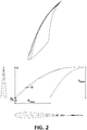
Figure 2 shows the profile, elevational, perspective, and side views of a surface according to the invention. - The leading edge is designed in several iterative steps. First, a coordinate system is established with an "x"-axis in the base of the profile of the lifting structure and a "y"-axis orthogonal thereto and extending from the midpoint of the base of the profile to the vertex of the structure. The curve starts at point (0,0), the length "L1" of which, according to the maximum thickness "Ho" in the base, is defined by the equation L1 = 0.0510H0 2 - 0.0790H0 + 15.5790.
- The shape of the curve is obtained by means of the equation:

- The maximum height on the "x"-axis of said curve is reached at point "y1/2" and has a value of x = 0.0137(L1)1.4144.
- This polynomial function is obtained from studying the caudal fins of sharks in 3D format with the help of Plot Digitizer software, obtaining the values of the points on the "x"-axis and "y"-axis of a graph from the image of the curve. The inventors then performed fitting with respect to the polynomial function which better assured a reduction in the coefficient of friction (see below).
- Once the first segment of the curve has been calculated, the second one is calculated in a similar manner, where "H1" is the thickness of the profile at the height "y1" at which the first curve ends, such that L2 = 0.0510H1 2- 0.0790H1 + 15.5790.
- The shape of the curve being that indicated by the equation:

- The maximum height on the "x"-axis in that second segment, which is reached at point "L1+L2/2", has a value of x = 0.0137(L2)1.4944
- As can be seen in
Figure 2 , the elevation of the lifting structure is not modified, although a transverse sectioning thereof will obviously show the difference in depth between different segments. - The depth of impact "D" measured with respect to the leading edge of the profile is dynamically calculated from a maximum value at point y = 0 to a value equal to zero at point "ymax". The maximum value of "D", i.e., "Do", is in the range of 0.25% to 0.31% of the chord length of the first NACA section "Pmax" of the structure to be modified. Said range is obtained from the most preferred "Pmax" value of 0.28% to which a correction factor of ±10% is applied.
- The edge is scalable to any size and can be applied to airborne or waterborne lifting structures.
- In the experimental results shown below, the edge of the invention applied to a hydrodynamic stabilizer has shown a reduction in the drag coefficient of 1% compared with an identical model with the smooth leading edge (see Table 1 below).
- The hydrodynamic efficiency of the models has been evaluated as follows: a model with an edge according to the aforementioned invention and a model with a smooth edge were reconstructed by means of software. Next, by means of a computational fluid dynamics (CFD) analysis using the ANSYS Fluent software, the drag coefficients (Cd), velocity field, and pressures were compared with the surface the leading edge of which is smooth. The comparison was carried out for two velocities (2 and 5 m/s) and three different angles of attack (0°, 15°, and 45°).
- To that end, the CAD file of the hydrodynamic stabilizer was supplied in the IGS/STEP format and the CFD model was generated based on said file. The CAD of the geometry was also supplied in the same format with the smooth leading edge.
- The study conditions were first established, defining: a) the geometry of the virtual control volume in which analyses were performed (7 meters long, 3 meters wide, and 1.5 meters tall; b) the most suitable meshing characteristics to be used in the models. In this last case, a mesh sensitivity analysis was included for selecting the ideal number of cells for the purpose of optimizing computational effort.
- Thereafter, a layer of cells was established around the hydrodynamic stabilizer which allows capturing the boundary layer around same (with special care in the area of the leading edge) and moderate mesh growth towards the outside was then applied.
- Three parameters were analyzed for the influence thereof on the drag coefficient "Cd": the velocity, the angle of attack, and the profile of the leading edge. The drag coefficient is defined as:

- The results of the CFD analysis indicate that the proposed leading edge has a smaller drag coefficient than its smooth counterpart in all the studied configurations and that the average reduction in the resistance of the leading model with a curved edge is 1.1%. Table 1 shows the percentage of reduction in the drag coefficient (Cd) of the stabilizer with a curved profile with respect to the wing with a smooth profile (1-(Cd of curved profile/Cd of smooth profile) x 100) in the different cases of study: two velocities (2 and 5 m/s) and three different angles of attack (0°, 15°, and 45°).
Angle v (m/s) 0° 15° 45° 1-(Cd of curved profile/Cd of smooth profile) x 100 2 3.7% 1.0% 0.6% 5 0.2% 0.9% 0.2% - On the other hand, the velocity fields for the type of curved profile are also more developed and have less impact on the downstream flow than in the case of a smooth profile.
Claims (3)
- Method for producing or designing a leading edge of a lifting structure comprising the following steps:a. establishing a coordinate system with an "x"-axis in the base of the profile of the lifting structure and a "y"-axis orthogonal thereto and extending from the midpoint of the base to the vertex of the structure;b. identifying the maximum thickness of the NACA section in the base of the profile "Ho" and starting to modify the surface profile at coordinate (0,0) by applying a curve, the length "L1" of which, according to the maximum thickness "Ho" in the base, is defined by the equation L1 = 0.0510H0 2 - 0.0790H0 + 15.5790, and the maximum height of which on the "x"-axis, which is located at point "y1/2", is defined by means of the relationship x = 0.0137(L1)1.4944, the shape of said curve being defined by means of the equation: (y-yo) = 0.0000000107x6 + 0.0000016382x5 - 0.0000794412x4 + 0.0010194142x3 + 0.0097205322x2 + 0.0136993913x;c. repeating step b using the thickness "H1" of the profile at the height "y1" to calculate the new length "L2" -such that y2 = L1+L2-, the maximum height on the "x"-axis, which is located at point "L1+L2/2", being defined by means of the relationship x = 0.0137(L2)1.4944, the shape of said curve being defined by means of the equation: (y-y1) = 0.0000000107x6 + 0.0000016382x5 - 0.0000794412x4 + 0.0010194142x3 + 0.0097205322x2 + 0.0136993913x; and so on and so forth.
- Method for producing or designing a leading edge of a lifting structure according to claim 1, wherein the depth of impact "D", calculated from the leading edge of the profile, ranges from a maximum value at point y = 0 to a value equal to zero at point "ymax"; and wherein "Do" is in the range of 0.25% to 0.31 % of the chord length of the first NACA section "Pmax" of the structure to be modified.
- Aero/hydrodynamic lifting structure provided with a leading edge designed according to the method of any of the preceding claims.
Applications Claiming Priority (1)
| Application Number | Priority Date | Filing Date | Title |
|---|---|---|---|
| PCT/ES2015/070960 WO2017114981A1 (en) | 2015-12-29 | 2015-12-29 | Method for designing leading edges and supporting structure provided with said edge |
Publications (3)
| Publication Number | Publication Date |
|---|---|
| EP3399181A1 true EP3399181A1 (en) | 2018-11-07 |
| EP3399181A4 EP3399181A4 (en) | 2019-12-11 |
| EP3399181B1 EP3399181B1 (en) | 2021-11-24 |
Family
ID=59225891
Family Applications (1)
| Application Number | Title | Priority Date | Filing Date |
|---|---|---|---|
| EP15912053.4A Active EP3399181B1 (en) | 2015-12-29 | 2015-12-29 | Method for designing leading edges and supporting structure provided with said edge |
Country Status (4)
| Country | Link |
|---|---|
| US (1) | US10746156B2 (en) |
| EP (1) | EP3399181B1 (en) |
| ES (1) | ES2906635T3 (en) |
| WO (1) | WO2017114981A1 (en) |
Family Cites Families (8)
| Publication number | Priority date | Publication date | Assignee | Title |
|---|---|---|---|---|
| GB791563A (en) * | 1955-05-02 | 1958-03-05 | Joseph Vaghi | Improvements relating to structures for use as an airplane wing, a propeller blade, a blower or fan blade |
| US6431498B1 (en) * | 2000-06-30 | 2002-08-13 | Philip Watts | Scalloped wing leading edge |
| EP1805412B1 (en) * | 2004-10-18 | 2016-03-02 | Whalepower Corporation | Turbine and compressor employing tubercle leading edge rotor design |
| KR101016010B1 (en) * | 2009-04-08 | 2011-02-23 | 건국대학교 산학협력단 | Rotor blade for rotary wing aircraft having deformable protrusions to reduce BVI Noiseblade vortex interaction noise |
| JP5386433B2 (en) * | 2010-05-10 | 2014-01-15 | 株式会社日立製作所 | Blade design device, blade design method, blade designed using the blade design method, and turbomachine using the blade |
| US8789793B2 (en) * | 2011-09-06 | 2014-07-29 | Airbus Operations S.L. | Aircraft tail surface with a leading edge section of undulated shape |
| US9249666B2 (en) * | 2011-12-22 | 2016-02-02 | General Electric Company | Airfoils for wake desensitization and method for fabricating same |
| EP2885206A4 (en) * | 2012-08-16 | 2016-03-16 | Adelaide Res &Innovation Pty Ltd | Improved wing configuration |
-
2015
- 2015-12-29 WO PCT/ES2015/070960 patent/WO2017114981A1/en active Application Filing
- 2015-12-29 EP EP15912053.4A patent/EP3399181B1/en active Active
- 2015-12-29 ES ES15912053T patent/ES2906635T3/en active Active
- 2015-12-29 US US16/067,175 patent/US10746156B2/en active Active
Also Published As
| Publication number | Publication date |
|---|---|
| US20190093626A1 (en) | 2019-03-28 |
| WO2017114981A1 (en) | 2017-07-06 |
| EP3399181A4 (en) | 2019-12-11 |
| EP3399181B1 (en) | 2021-11-24 |
| ES2906635T3 (en) | 2022-04-19 |
| US10746156B2 (en) | 2020-08-18 |
Similar Documents
| Publication | Publication Date | Title |
|---|---|---|
| Xiao et al. | Flow control for VATT by fixed and oscillating flap | |
| US20120166148A1 (en) | Method of designing natural laminar flow wing for reynolds numbers equivalent to actual supersonic aircraft | |
| EP2275671A1 (en) | System and method for designing airfoils | |
| CN104843173A (en) | Design method of low-noise aircraft propeller | |
| Abbaspour et al. | Unsteady flow over offshore wind turbine airfoils and aerodynamic loads with computational fluid dynamic simulations | |
| Crippa | Improvement of unstructured computational fluid dynamics simulations through novel mesh generation methodologies | |
| Kondo et al. | Large-eddy simulations of owl-like wing under low Reynolds number conditions | |
| CN113602473A (en) | Inflatable wing based on obliquely swept gas beam | |
| Hasnaoui et al. | Asymptotic Modeling the Aerodynamic Coefficients of The NACA Airfoil | |
| Ivanov et al. | Application of the controlled boundary layer concept for the wall interference reduction | |
| EP3399181B1 (en) | Method for designing leading edges and supporting structure provided with said edge | |
| Zahle et al. | Design of the LRP airfoil series using 2D CFD | |
| Bliamisa et al. | Modeling Surface Riblets Skin Friction Reduction Effect with the Use of Computational Fluid Dynamics. | |
| Morton | Detached-eddy simulations of vortex breakdown over a 70-degree delta wing | |
| CN105787217B (en) | A kind of optimum design method of aircraft ripple aerofoil profile | |
| EP3470329B1 (en) | Wing and aircraft | |
| Schirra et al. | Highly non-planar Lifting Systems: A relative assessment of existing Potential-Methodologies to accurately estimate the Induced Drag | |
| Ghoreyshi et al. | NATO AVT--316, Multi-Swept Combat Wing Design–Aerodynamic Ways Towards a Robust Flight Envelope | |
| CN113353285B (en) | Method and system for determining rotor wing profile | |
| JP7015582B2 (en) | Wings and aircraft | |
| Da Ronch et al. | A preliminary investigation into icing accretion around a wavy leading-edge wing | |
| Isaev et al. | Optimization of the slot suction of air from a circular vortex cell on a thick NACA0022 airfoil with a maximum lift–drag ratio | |
| Körpe et al. | Multi-objective morphing wing optimization for an Unmanned Air Vehicle | |
| Rodi | An examination of crossflow between waverider flowfield planes | |
| Hussain | Computational Analysis of Aerodynamic Effects on Commercial and Delta Wing at Various Twist |
Legal Events
| Date | Code | Title | Description |
|---|---|---|---|
| STAA | Information on the status of an ep patent application or granted ep patent |
Free format text: STATUS: THE INTERNATIONAL PUBLICATION HAS BEEN MADE |
|
| PUAI | Public reference made under article 153(3) epc to a published international application that has entered the european phase |
Free format text: ORIGINAL CODE: 0009012 |
|
| STAA | Information on the status of an ep patent application or granted ep patent |
Free format text: STATUS: REQUEST FOR EXAMINATION WAS MADE |
|
| 17P | Request for examination filed |
Effective date: 20180727 |
|
| AK | Designated contracting states |
Kind code of ref document: A1 Designated state(s): AL AT BE BG CH CY CZ DE DK EE ES FI FR GB GR HR HU IE IS IT LI LT LU LV MC MK MT NL NO PL PT RO RS SE SI SK SM TR |
|
| AX | Request for extension of the european patent |
Extension state: BA ME |
|
| DAV | Request for validation of the european patent (deleted) | ||
| DAX | Request for extension of the european patent (deleted) | ||
| A4 | Supplementary search report drawn up and despatched |
Effective date: 20191112 |
|
| RIC1 | Information provided on ipc code assigned before grant |
Ipc: B63B 1/00 20060101ALI20191106BHEP Ipc: F03B 3/12 20060101ALI20191106BHEP Ipc: F03D 1/06 20060101AFI20191106BHEP |
|
| STAA | Information on the status of an ep patent application or granted ep patent |
Free format text: STATUS: EXAMINATION IS IN PROGRESS |
|
| 17Q | First examination report despatched |
Effective date: 20200529 |
|
| STAA | Information on the status of an ep patent application or granted ep patent |
Free format text: STATUS: EXAMINATION IS IN PROGRESS |
|
| GRAP | Despatch of communication of intention to grant a patent |
Free format text: ORIGINAL CODE: EPIDOSNIGR1 |
|
| STAA | Information on the status of an ep patent application or granted ep patent |
Free format text: STATUS: GRANT OF PATENT IS INTENDED |
|
| INTG | Intention to grant announced |
Effective date: 20210611 |
|
| GRAS | Grant fee paid |
Free format text: ORIGINAL CODE: EPIDOSNIGR3 |
|
| GRAA | (expected) grant |
Free format text: ORIGINAL CODE: 0009210 |
|
| STAA | Information on the status of an ep patent application or granted ep patent |
Free format text: STATUS: THE PATENT HAS BEEN GRANTED |
|
| AK | Designated contracting states |
Kind code of ref document: B1 Designated state(s): AL AT BE BG CH CY CZ DE DK EE ES FI FR GB GR HR HU IE IS IT LI LT LU LV MC MK MT NL NO PL PT RO RS SE SI SK SM TR |
|
| REG | Reference to a national code |
Ref country code: GB Ref legal event code: FG4D |
|
| REG | Reference to a national code |
Ref country code: AT Ref legal event code: REF Ref document number: 1450053 Country of ref document: AT Kind code of ref document: T Effective date: 20211215 |
|
| REG | Reference to a national code |
Ref country code: DE Ref legal event code: R096 Ref document number: 602015075328 Country of ref document: DE |
|
| REG | Reference to a national code |
Ref country code: IE Ref legal event code: FG4D |
|
| REG | Reference to a national code |
Ref country code: SE Ref legal event code: TRGR |
|
| REG | Reference to a national code |
Ref country code: NL Ref legal event code: FP |
|
| REG | Reference to a national code |
Ref country code: LT Ref legal event code: MG9D |
|
| REG | Reference to a national code |
Ref country code: AT Ref legal event code: MK05 Ref document number: 1450053 Country of ref document: AT Kind code of ref document: T Effective date: 20211124 |
|
| REG | Reference to a national code |
Ref country code: ES Ref legal event code: FG2A Ref document number: 2906635 Country of ref document: ES Kind code of ref document: T3 Effective date: 20220419 |
|
| PG25 | Lapsed in a contracting state [announced via postgrant information from national office to epo] |
Ref country code: RS Free format text: LAPSE BECAUSE OF FAILURE TO SUBMIT A TRANSLATION OF THE DESCRIPTION OR TO PAY THE FEE WITHIN THE PRESCRIBED TIME-LIMIT Effective date: 20211124 Ref country code: LT Free format text: LAPSE BECAUSE OF FAILURE TO SUBMIT A TRANSLATION OF THE DESCRIPTION OR TO PAY THE FEE WITHIN THE PRESCRIBED TIME-LIMIT Effective date: 20211124 Ref country code: FI Free format text: LAPSE BECAUSE OF FAILURE TO SUBMIT A TRANSLATION OF THE DESCRIPTION OR TO PAY THE FEE WITHIN THE PRESCRIBED TIME-LIMIT Effective date: 20211124 Ref country code: BG Free format text: LAPSE BECAUSE OF FAILURE TO SUBMIT A TRANSLATION OF THE DESCRIPTION OR TO PAY THE FEE WITHIN THE PRESCRIBED TIME-LIMIT Effective date: 20220224 Ref country code: AT Free format text: LAPSE BECAUSE OF FAILURE TO SUBMIT A TRANSLATION OF THE DESCRIPTION OR TO PAY THE FEE WITHIN THE PRESCRIBED TIME-LIMIT Effective date: 20211124 |
|
| PG25 | Lapsed in a contracting state [announced via postgrant information from national office to epo] |
Ref country code: IS Free format text: LAPSE BECAUSE OF FAILURE TO SUBMIT A TRANSLATION OF THE DESCRIPTION OR TO PAY THE FEE WITHIN THE PRESCRIBED TIME-LIMIT Effective date: 20220324 Ref country code: PT Free format text: LAPSE BECAUSE OF FAILURE TO SUBMIT A TRANSLATION OF THE DESCRIPTION OR TO PAY THE FEE WITHIN THE PRESCRIBED TIME-LIMIT Effective date: 20220324 Ref country code: PL Free format text: LAPSE BECAUSE OF FAILURE TO SUBMIT A TRANSLATION OF THE DESCRIPTION OR TO PAY THE FEE WITHIN THE PRESCRIBED TIME-LIMIT Effective date: 20211124 Ref country code: NO Free format text: LAPSE BECAUSE OF FAILURE TO SUBMIT A TRANSLATION OF THE DESCRIPTION OR TO PAY THE FEE WITHIN THE PRESCRIBED TIME-LIMIT Effective date: 20220224 Ref country code: LV Free format text: LAPSE BECAUSE OF FAILURE TO SUBMIT A TRANSLATION OF THE DESCRIPTION OR TO PAY THE FEE WITHIN THE PRESCRIBED TIME-LIMIT Effective date: 20211124 Ref country code: HR Free format text: LAPSE BECAUSE OF FAILURE TO SUBMIT A TRANSLATION OF THE DESCRIPTION OR TO PAY THE FEE WITHIN THE PRESCRIBED TIME-LIMIT Effective date: 20211124 Ref country code: GR Free format text: LAPSE BECAUSE OF FAILURE TO SUBMIT A TRANSLATION OF THE DESCRIPTION OR TO PAY THE FEE WITHIN THE PRESCRIBED TIME-LIMIT Effective date: 20220225 |
|
| PG25 | Lapsed in a contracting state [announced via postgrant information from national office to epo] |
Ref country code: SM Free format text: LAPSE BECAUSE OF FAILURE TO SUBMIT A TRANSLATION OF THE DESCRIPTION OR TO PAY THE FEE WITHIN THE PRESCRIBED TIME-LIMIT Effective date: 20211124 Ref country code: SK Free format text: LAPSE BECAUSE OF FAILURE TO SUBMIT A TRANSLATION OF THE DESCRIPTION OR TO PAY THE FEE WITHIN THE PRESCRIBED TIME-LIMIT Effective date: 20211124 Ref country code: RO Free format text: LAPSE BECAUSE OF FAILURE TO SUBMIT A TRANSLATION OF THE DESCRIPTION OR TO PAY THE FEE WITHIN THE PRESCRIBED TIME-LIMIT Effective date: 20211124 Ref country code: EE Free format text: LAPSE BECAUSE OF FAILURE TO SUBMIT A TRANSLATION OF THE DESCRIPTION OR TO PAY THE FEE WITHIN THE PRESCRIBED TIME-LIMIT Effective date: 20211124 Ref country code: DK Free format text: LAPSE BECAUSE OF FAILURE TO SUBMIT A TRANSLATION OF THE DESCRIPTION OR TO PAY THE FEE WITHIN THE PRESCRIBED TIME-LIMIT Effective date: 20211124 Ref country code: CZ Free format text: LAPSE BECAUSE OF FAILURE TO SUBMIT A TRANSLATION OF THE DESCRIPTION OR TO PAY THE FEE WITHIN THE PRESCRIBED TIME-LIMIT Effective date: 20211124 |
|
| REG | Reference to a national code |
Ref country code: CH Ref legal event code: PL |
|
| REG | Reference to a national code |
Ref country code: DE Ref legal event code: R097 Ref document number: 602015075328 Country of ref document: DE |
|
| PG25 | Lapsed in a contracting state [announced via postgrant information from national office to epo] |
Ref country code: MC Free format text: LAPSE BECAUSE OF FAILURE TO SUBMIT A TRANSLATION OF THE DESCRIPTION OR TO PAY THE FEE WITHIN THE PRESCRIBED TIME-LIMIT Effective date: 20211124 |
|
| REG | Reference to a national code |
Ref country code: BE Ref legal event code: MM Effective date: 20211231 |
|
| PLBE | No opposition filed within time limit |
Free format text: ORIGINAL CODE: 0009261 |
|
| STAA | Information on the status of an ep patent application or granted ep patent |
Free format text: STATUS: NO OPPOSITION FILED WITHIN TIME LIMIT |
|
| PG25 | Lapsed in a contracting state [announced via postgrant information from national office to epo] |
Ref country code: LU Free format text: LAPSE BECAUSE OF NON-PAYMENT OF DUE FEES Effective date: 20211229 Ref country code: IE Free format text: LAPSE BECAUSE OF NON-PAYMENT OF DUE FEES Effective date: 20211229 Ref country code: AL Free format text: LAPSE BECAUSE OF FAILURE TO SUBMIT A TRANSLATION OF THE DESCRIPTION OR TO PAY THE FEE WITHIN THE PRESCRIBED TIME-LIMIT Effective date: 20211124 |
|
| 26N | No opposition filed |
Effective date: 20220825 |
|
| PG25 | Lapsed in a contracting state [announced via postgrant information from national office to epo] |
Ref country code: SI Free format text: LAPSE BECAUSE OF FAILURE TO SUBMIT A TRANSLATION OF THE DESCRIPTION OR TO PAY THE FEE WITHIN THE PRESCRIBED TIME-LIMIT Effective date: 20211124 Ref country code: BE Free format text: LAPSE BECAUSE OF NON-PAYMENT OF DUE FEES Effective date: 20211231 |
|
| PG25 | Lapsed in a contracting state [announced via postgrant information from national office to epo] |
Ref country code: LI Free format text: LAPSE BECAUSE OF NON-PAYMENT OF DUE FEES Effective date: 20211231 Ref country code: CH Free format text: LAPSE BECAUSE OF NON-PAYMENT OF DUE FEES Effective date: 20211231 |
|
| PGFP | Annual fee paid to national office [announced via postgrant information from national office to epo] |
Ref country code: NL Payment date: 20221226 Year of fee payment: 8 |
|
| PG25 | Lapsed in a contracting state [announced via postgrant information from national office to epo] |
Ref country code: CY Free format text: LAPSE BECAUSE OF FAILURE TO SUBMIT A TRANSLATION OF THE DESCRIPTION OR TO PAY THE FEE WITHIN THE PRESCRIBED TIME-LIMIT Effective date: 20211124 |
|
| PG25 | Lapsed in a contracting state [announced via postgrant information from national office to epo] |
Ref country code: HU Free format text: LAPSE BECAUSE OF FAILURE TO SUBMIT A TRANSLATION OF THE DESCRIPTION OR TO PAY THE FEE WITHIN THE PRESCRIBED TIME-LIMIT; INVALID AB INITIO Effective date: 20151229 |
|
| REG | Reference to a national code |
Ref country code: DE Ref legal event code: R082 Ref document number: 602015075328 Country of ref document: DE Representative=s name: KRAUS & LEDERER PARTGMBB, DE |
|
| PGFP | Annual fee paid to national office [announced via postgrant information from national office to epo] |
Ref country code: GB Payment date: 20231227 Year of fee payment: 9 |
|
| PGFP | Annual fee paid to national office [announced via postgrant information from national office to epo] |
Ref country code: SE Payment date: 20231227 Year of fee payment: 9 Ref country code: IT Payment date: 20231220 Year of fee payment: 9 Ref country code: FR Payment date: 20231227 Year of fee payment: 9 |
|
| PGFP | Annual fee paid to national office [announced via postgrant information from national office to epo] |
Ref country code: ES Payment date: 20240105 Year of fee payment: 9 |
|
| PG25 | Lapsed in a contracting state [announced via postgrant information from national office to epo] |
Ref country code: MK Free format text: LAPSE BECAUSE OF FAILURE TO SUBMIT A TRANSLATION OF THE DESCRIPTION OR TO PAY THE FEE WITHIN THE PRESCRIBED TIME-LIMIT Effective date: 20211124 |
|
| PGFP | Annual fee paid to national office [announced via postgrant information from national office to epo] |
Ref country code: DE Payment date: 20231229 Year of fee payment: 9 |