EP3399113A1 - Plumbing unit - Google Patents
Plumbing unit Download PDFInfo
- Publication number
- EP3399113A1 EP3399113A1 EP17169696.6A EP17169696A EP3399113A1 EP 3399113 A1 EP3399113 A1 EP 3399113A1 EP 17169696 A EP17169696 A EP 17169696A EP 3399113 A1 EP3399113 A1 EP 3399113A1
- Authority
- EP
- European Patent Office
- Prior art keywords
- plumbing
- plumbing element
- conduit
- waste conduit
- waste
- Prior art date
- Legal status (The legal status is an assumption and is not a legal conclusion. Google has not performed a legal analysis and makes no representation as to the accuracy of the status listed.)
- Pending
Links
Images


Classifications
-
- E—FIXED CONSTRUCTIONS
- E03—WATER SUPPLY; SEWERAGE
- E03C—DOMESTIC PLUMBING INSTALLATIONS FOR FRESH WATER OR WASTE WATER; SINKS
- E03C1/00—Domestic plumbing installations for fresh water or waste water; Sinks
- E03C1/12—Plumbing installations for waste water; Basins or fountains connected thereto; Sinks
- E03C1/122—Pipe-line systems for waste water in building
-
- F—MECHANICAL ENGINEERING; LIGHTING; HEATING; WEAPONS; BLASTING
- F16—ENGINEERING ELEMENTS AND UNITS; GENERAL MEASURES FOR PRODUCING AND MAINTAINING EFFECTIVE FUNCTIONING OF MACHINES OR INSTALLATIONS; THERMAL INSULATION IN GENERAL
- F16L—PIPES; JOINTS OR FITTINGS FOR PIPES; SUPPORTS FOR PIPES, CABLES OR PROTECTIVE TUBING; MEANS FOR THERMAL INSULATION IN GENERAL
- F16L41/00—Branching pipes; Joining pipes to walls
- F16L41/02—Branch units, e.g. made in one piece, welded, riveted
- F16L41/023—Y- pieces
Definitions
- the invention relates to a plumbing element, a plumbing element system and a building.
- sanitary rooms including bathrooms, lavatories or washrooms, of buildings with several floors and several apartments have water and sewage installations arranged into vertical shafts running inside structural walls, and into horizontal lines inside the floor/ceiling structures between the floors.
- the pipes and other conducting elements for water and waste (sewage) installations are often embedded within structures of stone, concrete, tile or other such building material.
- a plumbing element configured to conduct grey water is disclosed.
- the plumbing element may be configured to be mounted to a structure of a building.
- the building may comprise a vertical waste pipe system.
- the plumbing element may comprise a frame structure.
- the plumbing element may further comprise a waste conduit assembly for conducting grey water from a trap, the waste conduit assembly having an upper end and a lower end, wherein the lower end is connectable to the vertical waste pipe system of the building or to the upper end of the waste conduit assembly of a second plumbing element below the plumbing element and the upper end is connectable to the vertical waste pipe system of the building or to a lower end of the waste conduit assembly of a third plumbing element above the plumbing element.
- the waste conduit assembly may comprise a vertical waste conduit and a branch conduit, wherein the branch conduit opening to the vertical waste conduit and extending therefrom has an inlet for connecting to an outlet of the trap.
- a plumbing element configured to be mounted to a structure of a building.
- the plumbing element may be configured to conduct grey water.
- the building may comprise a vertical waste pipe system.
- the plumbing element may comprise a frame structure.
- the plumbing element may further comprise a waste conduit assembly for conducting grey water from a trap.
- the waste conduit assembly may have an upper end and a lower end, wherein the lower end is connectable to the vertical waste pipe system of the building or to the upper end of the waste conduit assembly of a second plumbing element below the plumbing element and the upper end is connectable to the vertical waste pipe system of the building or to a lower end of the waste conduit assembly of a third plumbing element above the plumbing element.
- the waste conduit assembly may comprise a vertical waste conduit and a branch conduit, wherein the branch conduit opening to the vertical waste conduit and extending therefrom has an inlet for connecting to an outlet of the trap.
- the plumbing element may be configured to be mounted to a wall of the building, to a floor of the building, to a ceiling of the building, or to two or more thereof.
- the frame structure may be self-supporting.
- the plumbing element may be a prefabricated plumbing element.
- prefabricated may refer to an element that is assembled in a factory as opposed to the installation site (i.e. the building, the structures of which the plumbing element is to be mounted to), and thus the element is provided to the installation site while already containing all the components of the element.
- the prefabricated element may comprise frame structure(s), and a waste conduit assembly according to one or more embodiments described in this specification.
- the prefabricated element may, in some embodiments, comprise a trap and/or a floor drain.
- grey water may refer to wastewater generated e.g. in households or office buildings from streams without fecal contamination, i.e. any or all streams except for the wastewater from toilets.
- Sources of greywater may include, e.g. sinks, showers, baths, washing machines for clothes or dish washers.
- greywater may contain fewer pathogens than domestic wastewater, it is generally safer to handle and easier to treat and reuse onsite for toilet flushing, landscape or crop irrigation, and other non-potable uses.
- trap may refer to a water trap or a water lock.
- a trap as known in the art, is a plumbing component which, due to its shape, is capable of retaining an amount of water, e.g. grey water, after the water has passed through it, so that the retained water creates a seal that prevents gas, e.g. sewer gas, from passing through the trap.
- Components such as floor drains, but also other plumbing components, may comprise a trap.
- the trap is comprised by a floor drain (i.e. the trap is a part of a floor drain), the waste conduit assembly thereby being suitable for conducting grey water from the floor drain, and the branch conduit has an inlet for connecting to an outlet of the floor drain.
- the plumbing element is an element for forming a shower area (i.e. a shower element). In an embodiment, the plumbing element is an element for forming a bath area. The bath area may be used as an installation area of a bathtub. In an embodiment, the plumbing element is an element for forming a home utility room area. In an embodiment, the plumbing element is an element for forming an installation area of a washing machine.
- the vertical waste conduit may have a longitudinal central axis, and the inlet of the branch conduit may be disposed within a distance (D i ) of up to 650 mm, or up to 400 mm, of the longitudinal central axis of the vertical waste conduit.
- the distance D i may be up to 600 mm, or up to 550 mm, or up to 500 mm, or up to 450 mm.
- the height (h) of the branch conduit may be up to 400 mm, or in the range of 150 mm to 400 mm. In an embodiment, the height h may be up to 350 mm, or up to 300 mm, or up to 250 mm, or up to 200 mm. In an embodiment, the height h may be in the range of 200 mm to 400 mm, or 250 to 400 mm.
- the lower end and the upper end of the waste conduit assembly may have longitudinal central axes that are are essentially in alignment.
- the vertical waste conduit may have a longitudinal central axis
- the branch conduit may have, at its end that opens to the vertical waste conduit, an inclined portion disposed at an angle of about 30° - 90°, or at an angle of about 30° - 60°, or at an angle of about 35° - 55°, or at an angle of about 45°, with respect to the longitudinal central axis of the vertical waste conduit.
- the waste conduit assembly may comprise a vertical waste pipe and a Y-shaped branch pipe fitting for connecting the vertical waste pipe to the outlet of the floor drain, wherein the Y-shaped branch pipe fitting is connected to the lower end of the vertical waste pipe, such that the branch of the Y-shaped branch pipe fitting forms at least a part of the branch conduit and the Y-shaped branch pipe fitting and the vertical waste pipe form at least a part of the vertical waste conduit.
- the Y-shaped branch pipe fitting may be a 30° - 90°, or a 30° - 60°, or a 35°-55°, or a 45° Y-shaped branch pipe fitting.
- the plumbing element may have an outlet opening configured to be connected to an inlet of the floor drain.
- the vertical waste conduit may have a longitudinal central axis, and the centre point of the outlet opening or the entire area of the outlet opening may be disposed within a distance of up to 700 mm, or up to 600 mm, or up to 400 mm of the longitudinal central axis of the vertical waste conduit.
- the plumbing element may comprise a collar plate, the collar plate comprising a plate having an outlet opening configured to be connected to an inlet of the floor drain and an edge defining the outlet opening.
- the collar plate may further comprise a collar surrounding the edge defining the outlet opening, the collar configured to extend into the inlet of the floor drain.
- the plate may be configured to be connectively sealed to at least one other horizontal structure, such as to a floor structure and/or to a horizontal building structure.
- horizontal may refer to a level that is perpendicular to the vertical direction.
- horizontal or essentially horizontal may refer to a level that is horizontal or at an angle of -5° to 5° of -2° to 2° of the horizontal level.
- the plumbing element may further comprise a vertical partition wall extending (or configured to extend) between the vertical waste conduit and a shower area, a bath area, a home utility room area, or an installation area of a washing machine formed by the plumbing element.
- the collar plate may further comprise a flange extending upwards from an edge of the plate, such that the flange is configured to rest against the vertical partition wall.
- the trap and/or floor drain may have a horizontal outlet.
- the trap and/or floor drain may have an inclined outlet.
- the trap and/or floor drain may have an outlet disposed at an angle of about 30 - 90°, or at an angle of about 35° - 55°, or at an angle of about 45° .
- the outlet of the trap and/or floor drain may be aligned with the inclined portion at the end of the branch conduit.
- the plumbing element may further comprise a conduit or pipelines for fresh water, an arrangement for connecting a tap assembly, a water meter, a sensor for monitoring water quality, automation cabling for the water meter and/or the sensor, and/or telecommunications cabling.
- a plumbing element system comprising a first plumbing element and a second plumbing element, wherein the first and second plumbing elements are located in two vertically adjoining spaces.
- the first and second plumbing elements may independently be any plumbing elements described in this specification.
- the first plumbing element comprises a first waste conduit assembly having an upper end and a lower end
- the second plumbing arrangement comprises a second waste conduit assembly having an upper end and a lower end.
- the lower end of the first waste conduit assembly is connected or connectable to the upper end of the second waste conduit assembly, such that the first and second plumbing elements are configured to form a continuous vertical waste conduit line between the vertically adjoining spaces.
- the continuous vertical waste conduit line may be configured to conduct grey water.
- a building comprising a plumbing element system according to one or more embodiments described in this specification is disclosed.
- the building may further comprise a second continuous vertical waste conduit line between the vertically adjoining spaces for conducting waste other than grey water conducted by the plumbing element system.
- waste water may be understood as referring to water, possibly containing other components, such as washing agents, that may be collected by a trap connected to or comprised by the plumbing element and that are to be conducted or conveyed away from the plumbing element. It may also, at least in some embodiments, be understood as encompassing or being grey water.
- the plumbing element may be prefabricated, less work at the installation site may be required to set up the waste conduit assembly required for the functioning of the area formed with the element.
- the plumbing element may be fast and easy to install, in particular when compared to assembling the waste conduit assembly required from individual components provided separately, and thus there may be less room for installation errors. Further, the quality of the plumbing element and its components may be improved, in particular when compared to setting up the waste conduit assembly required from individual components provided separately.
- the plumbing element requires a relatively small installation surface area, i.e. footprint. Servicing and replacing the components of the plumbing element may be relatively easy.
- the plumbing element may be stackable, e.g. a stackable module.
- the plumbing element allows installing two or more plumbing elements vertically in alignment into a continuous structure extending to two or more vertically adjoining spaces, thereby forming a continuous vertical waste conduit line and plumbing element system.
- stackable does not imply that the elements or modules, and in particular their frame structures, would necessarily be stacked directly on top of each other.
- a vertical waste conduit line may be separate from other vertical waste conduit lines e.g. for waste water originating from toilet fixtures and/or other fixtures, the amount of pipe conduits extending in the horizontal direction connecting the floor drain installed in connection with the plumbing element to the vertical waste conduit line may be significantly reduced.
- the plumbing element may also exhibit relatively low levels of noise caused by waste water flowing in the waste conduit assembly.
- the maximum noise levels allowed in habitable rooms, caused by waste water plumbing arrangements in use may be as low as 33 dB.
- minimizing noise levels may not be a trivial task; the mechanisms of noise generation and sound propagation through structures are not well known and may be quite complex.
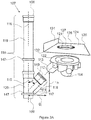
- Fig. 1A shows an overview of a plumbing element 100, in this embodiment an element for forming a shower area 130, i.e. a shower element.
- the plumbing element 100 of Fig. 1A shown in a perspective view, comprises a frame structure 105, which in this embodiment comprises one or more walls.
- the plumbing element 100 is shown as mounted inside a building 103; specifically, it is mounted against the wall 101 of the building 103.
- the frame structure 105 may rest on a horizontal building structure 102.
- the horizontal building structure 102 may be e.g. an intermediate floor or a concrete floor slab, or a floor/ceiling structure.
- the frame structure 105 and thereby the whole plumbing element 100, may be attached to the wall 101 of the building 103 using a suitable attachment arrangement, e.g. nuts and bolts.
- Any floor structures 106 (not shown in this Fig. but described in more detail below) that may be a part of the element or that are formed e.g. by casting during the installation of the plumbing element may be attached to the horizontal building structure 102 and/or to the wall 101.
- the frame structure 105 of the plumbing element 100 may be attached to a ceiling 140 and/or to the wall 101 of the building 103. In this schematic Fig., only sections of the horizontal building structure 102 and of the ceiling 140 are shown.
- the frame structure 105 may be constructed e.g. from suitable board or sheet materials and may comprise a steel frame. Gypsum board or rock material based boards may be used for the surfaces of the frame structure or any parts thereof. It may be at least partially covered by a waterproofing membrane, when the element is in use. The waterproofing membrane may be added on site after the plumbing element 100 is mounted to a structure 101, 102 of the building 103.
- the frame structure 105 may comprise or be, but not necessarily, a continuous and/or monolithic structure.
- the plumbing element 100 comprises a waste conduit assembly 107, only a part of which is visible in this Fig.
- the waste conduit assembly 107 configured to conduct grey water is described in more detail below e.g. in the context of Figs. 2 to 4 .
- the plumbing element 100 can therefore, when in use, conduct grey water to the vertical waste pipe system of the building in which it is mounted.
- a vertical partition wall 129 may be disposed in front of the waste conduit assembly 107 for hiding the waste conduit assembly 107.
- Components of the plumbing element 100 that are disposed behind the vertical partition wall 129 in this Fig. are illustrated using dash lines.
- the frame structure 105, the horizontal building structure 102 and the vertical partition wall 129 define a shower area 130; the element thus forms the shower area.
- the floor 141 of the shower area 130 may be built or be prefabricated on the horizontal building structure 102 and optionally on any other floor structure 106.
- the waste conduit assembly 107 may also be supported to the horizontal building structure 102 e.g. via suitable support members.
- the vertical partition wall 129 may be made e.g. of a gypsum board.
- the vertical partition wall 129 may be mounted in place after the plumbing element 100 is mounted to the structures 101, 102 of the building 103.
- the exterior of the vertical partition wall 129 may be water resistant or wet sealing, but it is also possible to add a waterproofing membrane or tape 142 to the plumbing element, the waterproofing membrane or tape sealingly extending at least partially to the vertical partition wall 129 on its side facing the shower area 130.
- the plumbing element 100 comprises a collar plate 124 having an outlet opening 121.
- the outlet opening 121 is configured to be connected to and to open to an inlet 122 of a floor drain 114 comprising a trap for collecting waste water from the shower area 130; the floor drain is however not visible in this Fig., but examples thereof can be seen e.g. in Figs. 2 to 4 .
- the floor drain 114 may or may not be comprised by the plumbing element 100, as it may be provided separately.
- the collar plate 124 when installed and in use, may be generally horizontal or generally essentially horizontal.
- the collar plate 124 may be generally horizontal or generally essentially horizontal; however, the upper side of the collar plate 124 may be at least partially tilted, in particular tilted towards the outlet opening 121, so that when the shower is in use, water splashed on the floor 141 of the shower area 130 may flow towards the outlet opening 121.
- the outlet opening 121 is disposed at or near a corner of the plumbing element 100 according to this embodiment, other geometries are also possible.
- the element 100 is, in this embodiment, a shower element, i.e. an element for forming the shower area 130
- the element could alternatively be for forming a bath area (e.g. for installing a bathtub), a home utility room area, or an installation area of a washing machine.
- a bath area e.g. for installing a bathtub
- a home utility room area e.g. for installing a bathtub
- Any grey water obtainable from the shower area, bath area, home utility room area or installation area of a washing machine e.g. shower or bath water or water released by a washing machine, may be collected to a trap, for instance to a trap to which the outlet opening 121 shown in this Fig. opens.
- the collar plate 124 may assist in waterproofing the plumbing element 100. However, the collar plate 124 may also be omitted in some embodiments, e.g. such that the floor structure 106, which may be a part of the plumbing element 100 or constructed on site after the plumbing element 100 has been mounted, or possibly the horizontal building structure 102 has an outlet opening 121.
- the collar plate 124 may be, when mounted in place, connectively sealed with the horizontal building structure 102 and/or with the floor structure 106.
- the sealing may be provided e.g. with a waterproofing membrane or tape 142.
- the waterproofing membrane or tape 142 may extend at least partially to the frame structure 105 and/or to the vertical partition wall 129.
- the waterproofing membrane or tape 142 may be added before surfaces of the shower area (floor 141, surface cladding 144, tiling etc. shown in Fig. 1B ) are laid or otherwise installed.
- the plumbing element 100 may further comprise other plumbing components and/or other components.
- the plumbing element 100 may comprise one or more conduits or pipelines 133 for fresh water, although these are not necessarily included but may be installed on site.
- the conduits or pipelines 133 may be attached to the frame structure 105 and/or to the vertical partition wall 129 with suitable support members 143, such as brackets or clamps.
- suitable conduits or pipelines 133 may be e.g. cross-linked polyethylene (PEX) pipes for cold and hot water.
- PEX polyethylene
- the plumbing element may also comprise an arrangement 134 for connecting a tap assembly, e.g. a termination box and/or a tap fitting.
- the conduits or pipelines 133 may be connected to the arrangement 134 for connecting a tap assembly.
- the plumbing element 100 may further comprise e.g. a water meter, a sensor for monitoring water quality, automation cabling for the water meter and/or the sensor, and/or telecommunications cabling (not shown in this Fig.).
- the plumbing element 100 shown in Fig. 1B differs from that shown in Fig. 1A at least in that at least a part of the frame structure 105 and at least a part of the horizontal building structure 102 are covered by surface cladding 144, such as tiling or other suitable cladding material, and by the floor 141 of the shower area 130.
- the floor 141 may also be surface cladded e.g. by tiling.
- the floor 141, the surface cladding 144 and/or any other surfaces may be prefabricated, i.e. they may be provided as a part of the prefabricated plumbing element 100. However, alternatively or additionally, they may also be built on site when the plumbing element 100, e.g. the plumbing element as shown in Fig.
- the plumbing element 100 in Fig. 1B forms, when in use, a part of a shower that may include other components, e.g. a tap assembly (not shown).
- Other aspects of the embodiment shown in Fig. 1B are generally similar to those of the embodiment shown in Fig. 1A .
- Fig. 2A shows a part of an embodiment of a plumbing element 100 mounted on a horizontal structure 102, in this embodiment a floor/ceiling structure or an intermediate floor, when in use.
- Fig. 2 is intended as a schematic representation rather than an actual sectional view through the entire plumbing element, as the floor/ceiling structure 102 and certain parts of the plumbing element 100 are shown as a sectional view while certain other parts of the plumbing element 100 are shown as a side view.
- the plumbing element 100 again comprises a vertical frame structure 105, which may be self-supporting.
- An opening 145 for example a single opening or two separate openings, is provided in the floor/ceiling structure 102 for leading the lower end 109 of the waste conduit assembly 107 through the floor/ceiling structure 102 and optionally for providing room for the floor drain 114.
- the floor drain 114 when installed, may be held in place by a floor structure 106 formed of casting or floor mass (not shown in this Fig. for clarity but described in more detail in the context of Fig. 2B ).
- the waste conduit assembly 107 comprises a vertical waste conduit 110 and a branch conduit 111.
- the waste conduit assembly 107 may be at least partially preinsulated.
- the vertical waste conduit 110 may be at least partially surrounded by insulation 146.
- other parts of the waste conduit assembly 107 may also be provided with (pre)insulation for reducing noise caused by waste water flow in the waste conduit assembly 107.
- the plumbing element 100 further comprises a pipe support member 147 for supporting the waste conduit assembly 107, such as a bracket or a clamp.
- the pipe support member 147 is attached to the horizontal floor structure 102 in this embodiment, but one or more pipe support members 147 may, alternatively or additionally, be attached to the frame structure 105 and/or to the vertical partition wall 129.
- the plumbing element 100 may further comprise a fire collar (not shown for clarity) for preventing the spread of fire through the lead-through.
- the vertical waste conduit 110 is continuous.
- the branch conduit 111 extends from the vertical waste conduit 110 towards the shower area 130 and the floor drain 114 comprising a trap.
- the trap is not shown in the Figs. for clarity, but it is a part of the floor drain 114.
- the floor drain 114 could, in other embodiments, be replaced by another type of trap or another plumbing component comprising a trap.
- the branch conduit 111 opens to the vertical waste conduit 110 and has an inlet 112 to which an outlet 113 of the floor drain 114 may be directly connected, such that the outlet 113 of the floor drain 114 opens to the branch conduit 111.
- the inlet 112 of the branch conduit 111 may be standardized, such that it is configured to be attached to a floor drain 114 having a standardized outlet 113.
- the outlet 113 of the floor drain 114 and the inlet 112 of the branch conduit 111 may both have a diameter of 30 - 110 mm, e.g. 75 mm, such that they can be attached to each other directly. It may also be possible to attach the outlet 113 of the floor drain 114 to the inlet 112 of the branch conduit 111 via a suitable fitting.
- the floor drain 114 is thus in fluid connection with the vertical waste conduit 110. Should the floor drain 114 be replaced by another type of trap or another component comprising a trap, the inlet 112 of the branch conduit 111 could be connected to the outlet 113 of the trap or the component, either directly or via one or more suitable fittings or further components.
- noise levels caused by waste water flowing in the waste conduit assembly 107, when in use, may be relatively low.
- the plumbing element 100 comprises, in this embodiment, a collar plate 124.
- the plumbing element 100 may be provided with the collar plate 124 being separate from other components of the plumbing element 100, so that the collar plate 124 may be mounted in place after the floor drain 114 is installed and connected to the plumbing element 100.
- the collar plate 124 may improve the wet sealing of the plumbing element 100.
- the collar plate 124 is disposed at least partially on the horizontal building structure 102 and/or on the floor structure 106 and is, when mounted in place, connectively sealed with the horizontal building structure 102 and/or the floor structure 106.
- the sealing may be provided e.g. with a waterproofing membrane or tape 142.
- the collar plate 124 comprises a plate 126 having an outlet opening 121.
- the plate 126 may be essentially horizontal or horizontal, when the collar plate 124 is mounted in place. However, the plate 126 may be at least partially tilted, in particular towards the outlet opening 121 so that when the shower is in use, water splashed on the shower area 130 may flow towards the outlet opening 121.
- the outlet opening 121 is connected to and opens to an inlet 122 of the floor drain 114.
- the outlet opening 121 and the collar plate 124 may be configured to fit a predetermined trap or floor drain 114, e.g. a trap or floor drain of predetermined or standardized dimensions.
- the plate 126 has an edge 127 defining the outlet opening 121.
- the collar plate 124 comprises a collar 128 around the edge 127. The collar 128 extends from the plate 126 so that when the collar plate 124 is in place, the collar 128 extends downwards. The collar 128 thus extends into the inlet 122 of the trap or floor drain 114.
- the collar 128 may e.g.
- the collar plate 124 may be attached to the floor drain 114 e.g. by a thread or by screws.
- the collar plate 124 may further comprise a flange 131 extending upwards from an edge 132 of the plate 126. However, in other embodiments, the flange 131 may be omitted. Further, the collar plate 124 may comprise one or more flanges 131 at one or more edges 132 of the plate. The flange 131 may, when the collar plate 124 is mounted in place, be disposed on either side of the vertical partition wall 129 and may rest against the vertical partition wall 129. One or more flanges 131 may, additionally or alternatively, be arranged to rest against the frame structure 105 of the plumbing element 100.
- the vertical partition wall 129 extends along a face of the flange 131 so that the bottom edge of the vertical partition wall 129 rests against the upper side of the plate 126.
- the flange 131 rests against the side facing towards the vertical waste conduit 110, but the flange 131 may, in other embodiments, be disposed on the side of the vertical partition wall 129 facing the shower area 130.
- the collar plate 124 e.g. either the plate 126 and/or the flange 131, may be sealingly connected to the vertical partition wall 129.
- the main material of the collar plate 124 may be e.g. steel plate (zinc electroplated or hot galvanised), a plastic material, or a composite material, or any suitable material that is resistant to water.
- Fig. 2B shows the same part of the embodiment of the plumbing element 100 mounted on the horizontal structure 102, in this embodiment a floor/ceiling structure, as Fig. 2A , when in use.
- Fig. 2B differs from Fig. 2A at least in that the floor structure 106 holding the floor drain 114 in place is shown, again in a schematic partially cross-sectional view.
- the floor structure 106 may be formed e.g. of casting or a floor mass and may be constructed when installing the plumbing element 100, i.e. after the waste conduit assembly 107 is connected to the trap or floor drain 114, so it is not necessarily a part of the plumbing element.
- other types of floor structures could be a part of the plumbing element.
- FIG. 2A and 2B may be generally similar to those of the embodiment shown in Figs. 1A and 1B .
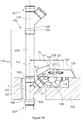
- Fig. 3A shows an embodiment of the waste conduit assembly 107, the floor drain 114 and the collar plate 124 of the plumbing element as an exploded view. Again, it should be understood that he floor drain 114 may or may not be a part of the plumbing element.
- the vertical waste conduit 110 is the vertical portion of the waste conduit assembly 107.
- the vertical waste conduit 110 may be straight or essentially straight.
- Pipe support members 147 may be provided for attaching the waste conduit assembly 107 to the frame structure 105 and/or to the floor structure 106. For clarity, the frame structure 105 and the floor structure 106 are not shown in this Fig.
- the vertical waste conduit 110 has an upper end 108 and a lower end 109.
- the lower end 109 has a longitudinal central axis 115.
- the upper end 108 has a longitudinal central axis 116.
- the longitudinal central axes 115 and 116 are central axes in the longitudinal direction of the vertical waste conduit 110.
- the longitudinal central axes 115, 116 may be essentially in alignment or in alignment. In an embodiment, the longitudinal central axes 115, 116 are essentially in alignment when the distance between them is at most 100 mm, or at most 50 mm, or at most 20 mm.
- the branch conduit 111 is the portion of the waste conduit assembly 107 extending from the vertical waste conduit 110.
- the inlet 112 of the branch conduit 111 is disposed within a distance D i of the longitudinal central axis 115 of the vertical waste conduit 110.
- the distance D i may be relatively small.
- the distance D i may be up to 650 mm, or up to 400 mm. With longer distances, and in particular relatively long horizontal portions of the branch conduit 111, noise levels may be higher.
- the distance D i may be measured from the furthermost edge of the inlet 112 as shown in this Fig. or, in some embodiments, from the central axis or centre point of the inlet 112.
- the floor drain 114 comprising a trap, which may or may not be a part of the plumbing element, has an outlet 113, the direction of which is not particularly limited.
- the inlet 112 of the branch conduit 111 may be configured to fit the outlet 113 of a predetermined floor drain 114.
- the inlet 112 may be be dimensioned such that it can be sealingly connected to a standard outlet 113 or to an outlet 113 of a standardized diameter or to an outlet 113 of predetermined dimensions.
- the branch conduit 111 has, at its end 117 that opens to the vertical waste conduit 110, an inclined portion 118.
- the inclined portion 118 may be straight or essentially straight.
- the inclined portion 118 may be disposed at an angle ⁇ of about 30° - 90° with respect to the longitudinal central axis 115 of the vertical waste conduit 110.
- the inclined portion 118 may be disposed at an angle ⁇ of about 30 - 89°, or at an angle ⁇ of about 30°-60°, or at an angle ⁇ of about 35° - 55°, or at an angle ⁇ of about 40° - 50°, or at an angle ⁇ of about 45°.
- Such angles of the inclined portion 118 may be associated with particularly low noise levels caused by waste water flowing in the waste conduit assembly 107, when in use.
- the branch conduit 111 does not have any essentially horizontal or horizontal portions, i.e. portions in which, when in use, water would flow essentially horizontally or horizontally.
- the waste conduit assembly 107 comprises a vertical waste pipe 119 and a Y-shaped branch pipe fitting 120 for connecting the vertical waste pipe 119 to the outlet 113 of the floor drain 114.
- the Y-shaped branch pipe fitting 120 may be removably connected to the lower end of the vertical waste pipe 119.
- the branch of the Y-shaped branch pipe fitting forms at least a part of the branch conduit 111, and the Y-shaped branch pipe fitting and the vertical waste pipe form at least a part of the vertical waste conduit 110.
- the Y-shaped branch pipe fitting 120 may be integral, i.e. monolithic. Instead of being a Y-shaped branch fitting, the branch fitting 120 may be T-shaped.
- the Y-shaped branch pipe fitting 120 may be a 30° - 90° Y-shaped branch pipe fitting, or a 30° - 89°, or a 30°-60°, or a 35° - 55°, or a 40 - 50°, or a 45° Y-shaped branch pipe fitting.
- the waste conduit assembly 107 may comprise further components, e.g. further fittings at the upper and/or lower end of the vertical waste pipe 119 or between the Y-shaped branch pipe fitting 120 and the inlet 112 of the branch conduit 111.
- the height h of the branch conduit 111 may be e.g. up to 400 mm, or in the range of 150 mm to 400 mm.
- the height h of the branch conduit 111 may be understood, in this embodiment, as the distance between the lowest edge of the end 117 of the branch conduit 111 and the topmost edge 149 of the branch conduit 111 in the vertical direction.
- the floor drain 114 further has an inlet 122 for collecting waste water from the shower area 130 (the shower area not shown in this Fig.).
- the dimensions, such as diameters, of individual conduits and fittings may be selected according to various factors, such as local regulations and requirements.
- FIG. 3A Other aspects of the embodiment shown in Fig. 3A may be generally similar to those of the embodiments shown in Figs. 1A to 2 .
- Fig. 3B differs from Fig. 3A at least in that the waste conduit assembly 107, the floor drain 114 and the collar plate 124 are shown as as perspective view when connected to each other.
- Fig. 3B also differs from Fig. 3A at least in that the lower end 109 of the waste conduit assembly 107, which in this embodiment is also the lower end of the Y-shaped branch pipe fitting 120, is connected to the upper end 108' of a waste conduit assembly 107' of a second plumbing element (other parts of the second plumbing element are omitted from the Fig. for clarity).
- the upper end 108 of the vertical waste conduit 110 which is also the upper end of the vertical waste pipe 119, is connected to the lower end 109" of a waste conduit assembly 107" of a third plumbing element (other parts of the third plumbing element are also omitted from the Fig. for clarity). They may be directly connected or connected via suitable fittings, e.g. via suitable joint fittings.
- the three waste conduit assemblies 107, 107', 107" of the three stacked plumbing elements thus form a continuous vertical waste conduit line.
- the vertical waste conduit 110 is not in scale in this schematic Fig.
- the central longitudinal axis 115' of the second waste conduit assembly 107', and in particular of its vertical waste conduit, of the second plumbing element may be essentially in alignment with or in alignment with the central longitudinal axis 115 of the vertical waste conduit 110.
- the outlet 113 of the floor drain 114 is disposed at an angle ⁇ of about 30 - 90°, or at an angle of about 35° - 89°, or at an angle of about 35° - 55°, or at an angle of about 40° - 50°. In this exemplary embodiment, the outlet 113 is disposed at an angle of about 45°.
- the angle ⁇ may be understood as the angle between the central axis 148 of the outlet 113 and the horizontal level.
- the outlet 113 of the floor drain 114 may be aligned with the inclined portion 118 at the end 117 of the branch conduit 111.
- the outlet opening 121 of the collar plate 124 is essentially round.
- the entire area of the outlet opening 121 is disposed within a distance D a from the longitudinal central axis 115 of the vertical waste conduit 110.
- the entire area of the inlet 122 of the floor drain 114 is disposed within a distance D a from the longitudinal central axis 115 of the vertical waste conduit 110.
- the distance D a may be up to 700 mm, or up to 600 mm, or up to 550 mm, or up to 500 mm, or up to 450 mm, or up to 400 mm.
- the collar 128 With the collar plate 124 attached to the floor drain 114, the collar 128 extends into the inlet 122 of the floor drain 114.
- the height of the collar 128 may be e.g. 15 - 25 mm.
- the collar 128 may rest against a seal of the inlet 122 so that it sealingly connects the collar plate 124 and thereby the entire the floor/ceiling structure 102 to the floor drain 114.
- Fig. 3B differs from Fig. 3A also in that the floor/ceiling structure 102 is shown schematically in sectional view.
- the floor structure 106 which may be constructed later, is not shown for clarity.
- An opening 145 is provided in the floor/ceiling structure 102 for leading the lower end 109 of the waste conduit assembly 107 through the floor/ceiling structure 102 through.
- the opening 145 (and also the floor/ceiling structure 102) has a height h o .
- the height h (not shown for clarity in this Fig.) of the branch conduit 111 may be equal to or smaller than the height h o of the opening 145.
- a height e.g. a height in the range of 150 mm to 400 mm, may allow for the branch conduit 111 to fit within the height h o of the opening 145; depending on the particular horizontal structure 102, the height thereof may be as low as 150 - 400 mm, for example, so that the vertical space in which the branch conduit 111 must be fitted in order to connect the floor drain 114 to the vertical waste conduit 110 may be quite limited.
- the casting or floor mass may thus form a floor structure 106.
- the floor drain 114 or other type of trap can be disposed, mainly or entirely, within the height h o , i.e. it can be disposed, mainly or entirely, within the floor structure 106.
- lowering the ceiling of the space below the floor/ceiling structure may be minimized or even avoided, so that room height does not necessarily have to be reduced.
- the useful height and volume of the space below the floor/ceiling structure e.g. the height and volume of a sanitary room below the floor/ceiling structure, can be maximized. Constructing costs may also be significantly reduced.
- FIG. 3B Other aspects of the embodiment shown in Fig. 3B may be generally similar to those of the embodiments shown in Figs. 1A to 3A .
- Fig. 4 illustrates another embodiment of the waste conduit assembly 107 and the floor drain 114 in an exploded view.
- the embodiment of Fig. 4 differs from the embodiment shown in Fig. 3A at least in that the floor drain 114 has a horizontal outlet 113.
- the branch conduit 111 has, at its end 117 that opens to the vertical waste conduit 110, an inclined portion 118.
- the inclined portion 118 may be straight or essentially straight.
- the inclined portion 118 may be disposed at an angle ⁇ of about 30° - 90° with respect to the longitudinal central axis 115 of the vertical waste conduit 110.
- the inclined portion 118 may be disposed at an angle ⁇ of about 30 - 89°, or at an angle ⁇ of about 30°-60°, or at an angle ⁇ of about 35° - 55°, or at an angle ⁇ of about 40° - 50°, or at an angle ⁇ of about 45°.
- the branch conduit 111 further comprises a bend portion 150.
- the bend portion 150 is formed at least partially by a bend pipe fitting, one end of which opens to the Y-shaped branch fitting 120 and the other end of which has an inlet 112 for connecting the branch conduit 111 to the outlet 113 of the floor drain 114 (or, in other embodiments, to an outlet of another type of trap).
- the bend portion may have a bend of about 30° - 90°, or about 30° - 60°, or about 35° - 55°, or about 40°-50°, or about 45°.
- the height h of the branch conduit 111 is measured as the distance between the lowest edge of the end 117 of the branch conduit 111 and the central axis 139 of the inlet 112 of the branch conduit 111 in the vertical direction.
- the height h may be e.g. up to 400 mm, or in the range of 150 mm to 400 mm, or any other height described in this specification. However, height h may be greater than 400 mm.
- the height h may be measured as the distance between the central axis 139 of the inlet 112 of the branch conduit 111 in the vertical direction and the central axis of the end 117 of the branch conduit 111.
- a height may be e.g. at least 10 mm, or up to 400 mm, or in the range of 10 mm to 400 mm.
- the inlet 112 of the branch conduit 111 is disposed within a distance D i of the longitudinal central axis 115 of the vertical waste conduit 110.
- the distance D i may be up to 650 mm, or up to 400 mm, or any other value for D i described in this specification.
- adding more parts to the waste conduit assembly 107, in particular to the branch conduit 111 may increase the distance D i undesirably, so that the floor drain 114 will be disposed further away from the vertical conduit 110.
- FIG. 4 Other aspects of the embodiment shown in Fig. 4 may be generally similar to those of the embodiments shown in Figs. 1A to 3B .
- the end 117 of the branch conduit 111 that opens to the vertical waste conduit 110 is not inclined but may be, for example, horizontal (i.e. the angle ⁇ may be substantially 90°, e.g. 89 - 91°). Other parts of such a branch conduit 111 may, however, be inclined.
- the branch conduit 111 may be provided by a swept or curved fitting instead of the Y-shaped branch fitting 120.
- the outlet 113 of the floor drain 114 may be vertical.
- the height h may be greater, so that the branch conduit 111 may take up more vertical space and may be difficult to fit in the space provided, in particular when the horizontal structure 102 of the building 103 is relatively thin.
- Custom fittings may be provided for providing a desired geometry for the waste conduit assembly 107.
- Fig. 5 shows an embodiment of the plumbing element 100 as a top view.
- the plumbing element 100 in particular a frame structure 105, is mounted in place and disposed against a wall 101 of a building.
- This exemplary embodiment differs from those shown in Figs. 1A to 4 at least in that the vertical waste conduit 110 is not arranged at or near a corner of the plumbing element 100 but near the midpoint of the portion of the frame structure 105 facing the wall 101.
- the plumbing element 100 also does not comprise a collar plate.
- a floor drain 114 or other trap (not shown), which may be a part of the plumbing element 100 or provided separately, has been connected to the plumbing element 100, the floor drain having an inlet 122, the entire area of which is disposed within a distance D a of the longitudinal central axis 115 of the vertical waste conduit 110.
- the distance D a may be e.g. up to 700 mm, or up to 650 mm, or up to 600 mm, or up to 550 mm, or up to 500 mm, or up to 450 mm, or up to 400 mm of the longitudinal central axis 115.
- the inlet 122 is round, although other shapes may also be contemplated.
- Other aspects of the embodiment shown in Fig. 5 may be generally similar to those of the embodiments shown in Figs. 1A to 4 .
- the embodiment of the plumbing element 100 illustrated in Fig. 6 differs from that shown in Fig. 5 at least in that the inlet 122 of the floor drain 114 (again not shown) is not round but rectangular and elongated.
- the inlet 122 has a centre point (midpoint) 123.
- the centre point 123 of the inlet 122 is disposed within a distance D c of the longitudinal central axis 115 of the vertical waste conduit 110.
- the distance D c may be e.g. up to 700 mm, or up to 650 mm, or up to 600 mm, or up to 550 mm, or up to 500 mm, or up to 450 mm, or up to 400 mm of the longitudinal central axis 115.
- Other aspects of the embodiment shown in Fig. 6 may be generally similar to those of the embodiments shown in Figs. 1A to 5 .
- Fig. 7 illustrates a plumbing element 100 for forming a shower area 130.
- the frame structure 105 is relatively small and has a rectangular or square cross-section. Such an element may take up relatively little space.
- the frame structure 105 is arranged against a wall 101 of a building and may hide the vertical waste conduit 110. Other parts of the waste conduit assembly 107 are not shown.
- the inlet 122 of a floor drain 114 or other type of trap is disposed within the shower area 130.
- An optional shower screen 125 may be provided, either as a part of the plumbing element 100 or installed on site, for preventing splashing of water outside of the shower area 130.
- the plumbing element 100 could be used to form e.g. a bath area, a home utility room area, or an installation area of a washing machine.
- Fig. 8 illustrates an embodiment in which the plumbing element 100, i.e. the frame structure 105, functions as a room divider.
- a short end of a longitudinal frame structure 105 is mounted against a wall 101 of the building.
- the plumbing element 100 may further comprise conduits or pipelines 133 for fresh water.
- the plumbing element 100 further comprises an additional component 154, such as a water meter, a sensor for monitoring water quality, automation cabling for the water meter and/or the sensor, and/or telecommunications cabling.
- inlets 122 of floor drains 114 or other types of traps are disposed on opposite sides of the longitudinal rectangular frame structure 105, so that the plumbing element 100 forms shower areas 130 on opposite sides of the frame structure 105.
- Such an embodiment may be useful in particular in sanitary rooms that are intended for the use of a large number of people, e.g. sanitary rooms in connection with locker rooms.
- One or more of the shower areas 130 could, in some embodiments, be e.g. a bath area, a home utility room area, or an installation area of a washing machine instead.
- Fig. 9 illustrates schematically a plumbing element system 135 and a building 103 comprising the system.
- Fig. 9 is intended as a schematic representation of the system rather than an actual sectional view through the entire system, as the horizontal structures, e.g. floor/ceiling structures 102, 102', 102" of the building 103 are shown as a sectional view while parts of the plumbing and other plumbing elements are shown as a side view.
- the plumbing element system 135 comprises a first plumbing element 100 and a second plumbing element 100' located in two vertically adjoining spaces 136 and 137, respectively.
- the two vertically adjoining spaces may be rooms, for instance toilets, bathrooms, washrooms or lavatories, separated by the floor/ceiling structure 102, the second plumbing element 100' located below the first plumbing element 100.
- the aspects of the embodiment of the plumbing elements shown in Fig. 9 may be generally similar to those of the embodiments shown in Figs. 1A to 8 .
- the plumbing elements 100, 100' and 100" may be prefabricated.
- the lower end 109 of the first waste conduit assembly 107 is, when in use, connected to the upper end 108' of the second waste conduit assembly 107', so that the first 100 and second 100' plumbing elements form a continuous vertical plumbing element system 135 and a continuous vertical waste conduit line 107, 107' between (and within) the vertically adjoining spaces 136, 137.
- the upper end 108 of the first plumbing element 100 is connected to the vertical waste pipe system 104b of the building 103.
- the lower end 109' of the second plumbing element 100' is connected to the vertical waste pipe system 104a of the building 103.
- Openings 145, 145' may be provided in the floor/ceiling structures 102, 102', 140 for leading the lower ends 109, 109' of the waste conduit assemblies 107, 107' through the floor/ceiling structures 102, 102'.
- the first and second waste conduit assemblies 107, 107' may be connected directly or via one or more suitable fittings.
- the plumbing element system 135 and the continuous vertical waste conduit line 107, 107' are configured to conduct grey water.
- the parts of the vertical waste pipe system 104a, 104b above and below the plumbing elements 100, 100' are thus in fluid connection via the continuous vertical waste conduit line 107, 107'.
- the first and second waste conduit assemblies 107, 107' may be essentially in alignment. However, as in any construction, there may be deviations from vertical alignment, as long as the vertical waste conduit line 107, 107' can be constructed using suitable fittings and is functional. For example, deviations of up to 100 mm, or up to 50 mm, may be tolerated. If necessary, waste conduit assemblies 107, 107' can still be connected in the presence of deviations from vertical alignment using suitable fittings, e.g. within horizontal building structures.
- the building 103 further comprises a second continuous vertical waste conduit line 138 between, and within, the vertically adjoining spaces 136, 137 for conducting waste other than waste water from the plumbing element system 135.
- the vertically adjoining spaces 136, 137 may contain suitable structures 151, 151' supporting toilet fixtures 152, 152'.
- the toilet fixtures 152, 152' may be in fluid connection with the second continuous vertical waste conduit line 138 via toilet waste conduits 153, 153', such that waste water (blackwater) from the toilet fixtures 152, 152' and possibly from other fixtures, such as sinks, may be conducted via the second continuous vertical waste conduit line 138.
- the second continuous vertical waste conduit line 138 is thus configured to conduct waste other than the grey water conducted by the plumbing element system 135.
- the waste other than the grey water conducted by the plumbing element system 135 may contain blackwater (sewage).
- the plumbing element system 135 forms its own separate continuous vertical waste conduit line 107, 107', there is no need to provide long horizontal runs of waste conduits from the plumbing elements 100, 100' to the second continuous vertical waste conduit line 138. It is also possible to collect or otherwise utilize the grey water conducted by the plumbing element system 135 separately for further use, because it does not contain any blackwater (sewage).
- lowering the ceiling of the space 137 below the floor/ceiling structure may be minimized or even avoided, so that room height does not necessarily have to be reduced.
- the useful height and volume of the space 137 below the floor/ceiling structure e.g. the height and volume of a sanitary room below the floor/ceiling structure, can be maximized. Constructing costs may also be significantly reduced.
- the embodiments described hereinbefore may be used in any combination with each other. Several of the embodiments may be combined together to form a further embodiment.
- a product, a system, a method or a use described in this specification may comprise at least one of the embodiments described hereinbefore. It will be understood that the benefits and advantages described above may relate to one embodiment or may relate to several embodiments. The embodiments are not limited to those that solve any or all of the stated problems or those that have any or all of the stated benefits and advantages. It will further be understood that reference to 'an' item refers to one or more of those items.
- the term "comprising" is used in this specification to mean including the feature(s) or act(s) followed thereafter, without excluding the presence of one or more additional features or acts.
Abstract
Description
- The invention relates to a plumbing element, a plumbing element system and a building.
- Historically, sanitary rooms, including bathrooms, lavatories or washrooms, of buildings with several floors and several apartments have water and sewage installations arranged into vertical shafts running inside structural walls, and into horizontal lines inside the floor/ceiling structures between the floors. In other words, the pipes and other conducting elements for water and waste (sewage) installations are often embedded within structures of stone, concrete, tile or other such building material. When renovations need to be done and the water and sewage installations need to be replaced, costly and time-consuming cutting-in operations may be needed to access the pipes.
- In newer buildings, modern constructions rules and building codes may require that all such pipelines should be installed so that they are accessible for maintenance, repair and future renovations without breaking the wall or floor/ceiling structures of the building. For example, water conduits leading fresh water from a mains line to a shower, a toilet or a washbasin must be surface-installed on the walls. Naturally, there are lead-through points for the pipes between floors and walls. In addition, modern building codes have strict requirements for wet sealing and water proofing, as well for constructions that allow possible leaks to be detected by leading the leaking water/liquid outside any closed structures where they become visible. Modern building codes also have requirements for noise levels, i.e. acceptable levels of sound coming from pipelines and conduits.
- These kinds of installations may be time-consuming and may require great precision from the persons conducting the installations to avoid any mistakes that could lead to water or moisture damages within the sanitary rooms or building structures. Further, long horizontal lines inside the floor/ceiling structures may be required to connect different sources of waste water into the vertical shafts running inside structural walls. Constructing such horizontal lines and connections typically requires space in the vertical direction and may increase the thickness of horizontal building structures, such as floor/ceiling structures or intermediate floors, which may require lowering of the ceiling and thereby diminished room height.
- This Summary is provided to introduce a selection of concepts in a simplified form that are further described below in the Detailed Description. This Summary is not intended to identify key features or essential features of the claimed subject matter, nor is it intended to be used to limit the scope of the claimed subject matter.
- A plumbing element configured to conduct grey water is disclosed. The plumbing element may be configured to be mounted to a structure of a building. The building may comprise a vertical waste pipe system. The plumbing element may comprise a frame structure. The plumbing element may further comprise a waste conduit assembly for conducting grey water from a trap, the waste conduit assembly having an upper end and a lower end, wherein the lower end is connectable to the vertical waste pipe system of the building or to the upper end of the waste conduit assembly of a second plumbing element below the plumbing element and the upper end is connectable to the vertical waste pipe system of the building or to a lower end of the waste conduit assembly of a third plumbing element above the plumbing element. The waste conduit assembly may comprise a vertical waste conduit and a branch conduit, wherein the branch conduit opening to the vertical waste conduit and extending therefrom has an inlet for connecting to an outlet of the trap.
- The accompanying drawings, which are included to provide a further understanding of the embodiments and constitute a part of this specification, illustrate various embodiments. In the drawings:
-
Fig. 1A is a perspective view of a plumbing element according to an embodiment; -
Fig. 1B illustrates a perspective view of a plumbing element according to another embodiment; -
Fig. 2A shows an embodiment of a plumbing element as a schematic view; -
Fig. 2B shows an embodiment of a plumbing element as a further schematic view; -
Fig. 3A illustrates an exploded view of an embodiment of a waste conduit assembly, a floor drain and a collar plate of a plumbing element; -
Fig. 3B illustrates a perspective view of an embodiment of a waste conduit assembly, a floor drain and a collar plate of a plumbing element; -
Fig. 4 shows another embodiment of a waste conduit assembly and a floor drain in an exploded view; -
Fig. 5 shows an embodiment of a plumbing element as a top view; -
Fig. 6 shows another embodiment of a plumbing element as a top view; -
Fig. 7 shows yet another embodiment of a plumbing element as a top view; -
Fig. 8 shows yet another embodiment of a plumbing element as a top view; and -
Fig. 9 illustrates an exemplary embodiment of a plumbing element system and a building. - A plumbing element configured to be mounted to a structure of a building is disclosed. The plumbing element may be configured to conduct grey water. The building may comprise a vertical waste pipe system. The plumbing element may comprise a frame structure. The plumbing element may further comprise a waste conduit assembly for conducting grey water from a trap. The waste conduit assembly may have an upper end and a lower end, wherein the lower end is connectable to the vertical waste pipe system of the building or to the upper end of the waste conduit assembly of a second plumbing element below the plumbing element and the upper end is connectable to the vertical waste pipe system of the building or to a lower end of the waste conduit assembly of a third plumbing element above the plumbing element. The waste conduit assembly may comprise a vertical waste conduit and a branch conduit, wherein the branch conduit opening to the vertical waste conduit and extending therefrom has an inlet for connecting to an outlet of the trap.
- The plumbing element may be configured to be mounted to a wall of the building, to a floor of the building, to a ceiling of the building, or to two or more thereof. The frame structure may be self-supporting.
- The plumbing element may be a prefabricated plumbing element. In the context of this specification, the term "prefabricated" may refer to an element that is assembled in a factory as opposed to the installation site (i.e. the building, the structures of which the plumbing element is to be mounted to), and thus the element is provided to the installation site while already containing all the components of the element. In particular, the prefabricated element may comprise frame structure(s), and a waste conduit assembly according to one or more embodiments described in this specification. The prefabricated element may, in some embodiments, comprise a trap and/or a floor drain.
- In the context of this specification, the term "grey water" (also spelled graywater, greywater, gray water) may refer to wastewater generated e.g. in households or office buildings from streams without fecal contamination, i.e. any or all streams except for the wastewater from toilets. Sources of greywater may include, e.g. sinks, showers, baths, washing machines for clothes or dish washers. As greywater may contain fewer pathogens than domestic wastewater, it is generally safer to handle and easier to treat and reuse onsite for toilet flushing, landscape or crop irrigation, and other non-potable uses.
- In the context of this specification, the term "trap" may refer to a water trap or a water lock. A trap, as known in the art, is a plumbing component which, due to its shape, is capable of retaining an amount of water, e.g. grey water, after the water has passed through it, so that the retained water creates a seal that prevents gas, e.g. sewer gas, from passing through the trap. Components such as floor drains, but also other plumbing components, may comprise a trap.
- In an embodiment, the trap is comprised by a floor drain (i.e. the trap is a part of a floor drain), the waste conduit assembly thereby being suitable for conducting grey water from the floor drain, and the branch conduit has an inlet for connecting to an outlet of the floor drain.
- In an embodiment, the plumbing element is an element for forming a shower area (i.e. a shower element). In an embodiment, the plumbing element is an element for forming a bath area. The bath area may be used as an installation area of a bathtub. In an embodiment, the plumbing element is an element for forming a home utility room area. In an embodiment, the plumbing element is an element for forming an installation area of a washing machine.
- The vertical waste conduit may have a longitudinal central axis, and the inlet of the branch conduit may be disposed within a distance (Di) of up to 650 mm, or up to 400 mm, of the longitudinal central axis of the vertical waste conduit. In an embodiment, the distance Di may be up to 600 mm, or up to 550 mm, or up to 500 mm, or up to 450 mm.
- The height (h) of the branch conduit may be up to 400 mm, or in the range of 150 mm to 400 mm. In an embodiment, the height h may be up to 350 mm, or up to 300 mm, or up to 250 mm, or up to 200 mm. In an embodiment, the height h may be in the range of 200 mm to 400 mm, or 250 to 400 mm.
- The lower end and the upper end of the waste conduit assembly may have longitudinal central axes that are are essentially in alignment.
- The vertical waste conduit may have a longitudinal central axis, and the branch conduit may have, at its end that opens to the vertical waste conduit, an inclined portion disposed at an angle of about 30° - 90°, or at an angle of about 30° - 60°, or at an angle of about 35° - 55°, or at an angle of about 45°, with respect to the longitudinal central axis of the vertical waste conduit.
- The waste conduit assembly may comprise a vertical waste pipe and a Y-shaped branch pipe fitting for connecting the vertical waste pipe to the outlet of the floor drain, wherein the Y-shaped branch pipe fitting is connected to the lower end of the vertical waste pipe, such that the branch of the Y-shaped branch pipe fitting forms at least a part of the branch conduit and the Y-shaped branch pipe fitting and the vertical waste pipe form at least a part of the vertical waste conduit. The Y-shaped branch pipe fitting may be a 30° - 90°, or a 30° - 60°, or a 35°-55°, or a 45° Y-shaped branch pipe fitting.
- The plumbing element may have an outlet opening configured to be connected to an inlet of the floor drain.
- The vertical waste conduit may have a longitudinal central axis, and the centre point of the outlet opening or the entire area of the outlet opening may be disposed within a distance of up to 700 mm, or up to 600 mm, or up to 400 mm of the longitudinal central axis of the vertical waste conduit.
- The plumbing element may comprise a collar plate, the collar plate comprising a plate having an outlet opening configured to be connected to an inlet of the floor drain and an edge defining the outlet opening. The collar plate may further comprise a collar surrounding the edge defining the outlet opening, the collar configured to extend into the inlet of the floor drain. The plate may be configured to be connectively sealed to at least one other horizontal structure, such as to a floor structure and/or to a horizontal building structure.
- In the context of this specification, the term "horizontal" may refer to a level that is perpendicular to the vertical direction. The term "horizontal" or "essentially horizontal" may refer to a level that is horizontal or at an angle of -5° to 5° of -2° to 2° of the horizontal level.
- The plumbing element may further comprise a vertical partition wall extending (or configured to extend) between the vertical waste conduit and a shower area, a bath area, a home utility room area, or an installation area of a washing machine formed by the plumbing element. The collar plate may further comprise a flange extending upwards from an edge of the plate, such that the flange is configured to rest against the vertical partition wall.
- The trap and/or floor drain may have a horizontal outlet. The trap and/or floor drain may have an inclined outlet.
- The trap and/or floor drain may have an outlet disposed at an angle of about 30 - 90°, or at an angle of about 35° - 55°, or at an angle of about 45° . The outlet of the trap and/or floor drain may be aligned with the inclined portion at the end of the branch conduit.
- The plumbing element may further comprise a conduit or pipelines for fresh water, an arrangement for connecting a tap assembly, a water meter, a sensor for monitoring water quality, automation cabling for the water meter and/or the sensor, and/or telecommunications cabling.
- A plumbing element system is also disclosed, comprising a first plumbing element and a second plumbing element, wherein the first and second plumbing elements are located in two vertically adjoining spaces. The first and second plumbing elements may independently be any plumbing elements described in this specification. The first plumbing element comprises a first waste conduit assembly having an upper end and a lower end, and the second plumbing arrangement comprises a second waste conduit assembly having an upper end and a lower end. The lower end of the first waste conduit assembly is connected or connectable to the upper end of the second waste conduit assembly, such that the first and second plumbing elements are configured to form a continuous vertical waste conduit line between the vertically adjoining spaces. The continuous vertical waste conduit line may be configured to conduct grey water.
- A building comprising a plumbing element system according to one or more embodiments described in this specification is disclosed. The building may further comprise a second continuous vertical waste conduit line between the vertically adjoining spaces for conducting waste other than grey water conducted by the plumbing element system.
- In the context of this specification, the term "waste water" may be understood as referring to water, possibly containing other components, such as washing agents, that may be collected by a trap connected to or comprised by the plumbing element and that are to be conducted or conveyed away from the plumbing element. It may also, at least in some embodiments, be understood as encompassing or being grey water.
- As the plumbing element may be prefabricated, less work at the installation site may be required to set up the waste conduit assembly required for the functioning of the area formed with the element. The plumbing element may be fast and easy to install, in particular when compared to assembling the waste conduit assembly required from individual components provided separately, and thus there may be less room for installation errors. Further, the quality of the plumbing element and its components may be improved, in particular when compared to setting up the waste conduit assembly required from individual components provided separately. The plumbing element requires a relatively small installation surface area, i.e. footprint. Servicing and replacing the components of the plumbing element may be relatively easy.
- The plumbing element may be stackable, e.g. a stackable module. In other words, the plumbing element allows installing two or more plumbing elements vertically in alignment into a continuous structure extending to two or more vertically adjoining spaces, thereby forming a continuous vertical waste conduit line and plumbing element system. However, the term stackable does not imply that the elements or modules, and in particular their frame structures, would necessarily be stacked directly on top of each other. As such a vertical waste conduit line may be separate from other vertical waste conduit lines e.g. for waste water originating from toilet fixtures and/or other fixtures, the amount of pipe conduits extending in the horizontal direction connecting the floor drain installed in connection with the plumbing element to the vertical waste conduit line may be significantly reduced.
- The plumbing element, at least according to certain embodiments, may also exhibit relatively low levels of noise caused by waste water flowing in the waste conduit assembly. For example, in some countries, the maximum noise levels allowed in habitable rooms, caused by waste water plumbing arrangements in use, may be as low as 33 dB. Thus minimizing noise levels may not be a trivial task; the mechanisms of noise generation and sound propagation through structures are not well known and may be quite complex.
- Reference will now be made in detail to embodiments, examples of which are illustrated in the accompanying drawings.
- The description below discloses some embodiments in such a detail that a person skilled in the art is able to utilize the embodiments based on the disclosure. Not all steps of the embodiments are discussed in detail, as many of the steps will be obvious for the person skilled in the art based on this specification.
- For reasons of simplicity, item numbers will be maintained in the following exemplary embodiments in the case of repeating components.
-
Fig. 1A shows an overview of aplumbing element 100, in this embodiment an element for forming ashower area 130, i.e. a shower element. Theplumbing element 100 ofFig. 1A , shown in a perspective view, comprises aframe structure 105, which in this embodiment comprises one or more walls. Theplumbing element 100 is shown as mounted inside abuilding 103; specifically, it is mounted against thewall 101 of thebuilding 103. Theframe structure 105 may rest on ahorizontal building structure 102. Thehorizontal building structure 102 may be e.g. an intermediate floor or a concrete floor slab, or a floor/ceiling structure. Theframe structure 105, and thereby thewhole plumbing element 100, may be attached to thewall 101 of thebuilding 103 using a suitable attachment arrangement, e.g. nuts and bolts. Any floor structures 106 (not shown in this Fig. but described in more detail below) that may be a part of the element or that are formed e.g. by casting during the installation of the plumbing element may be attached to thehorizontal building structure 102 and/or to thewall 101. Theframe structure 105 of theplumbing element 100 may be attached to aceiling 140 and/or to thewall 101 of thebuilding 103. In this schematic Fig., only sections of thehorizontal building structure 102 and of theceiling 140 are shown. - The
frame structure 105 may be constructed e.g. from suitable board or sheet materials and may comprise a steel frame. Gypsum board or rock material based boards may be used for the surfaces of the frame structure or any parts thereof. It may be at least partially covered by a waterproofing membrane, when the element is in use. The waterproofing membrane may be added on site after theplumbing element 100 is mounted to astructure building 103. Theframe structure 105 may comprise or be, but not necessarily, a continuous and/or monolithic structure. - The
plumbing element 100 comprises awaste conduit assembly 107, only a part of which is visible in this Fig. Thewaste conduit assembly 107 configured to conduct grey water is described in more detail below e.g. in the context ofFigs. 2 to 4 . Theplumbing element 100 can therefore, when in use, conduct grey water to the vertical waste pipe system of the building in which it is mounted. Avertical partition wall 129 may be disposed in front of thewaste conduit assembly 107 for hiding thewaste conduit assembly 107. Components of theplumbing element 100 that are disposed behind thevertical partition wall 129 in this Fig. are illustrated using dash lines. Theframe structure 105, thehorizontal building structure 102 and thevertical partition wall 129 define ashower area 130; the element thus forms the shower area. When theplumbing element 100 is mounted in place, the surfaces of theplumbing element 100 are finished and the shower is in use, a person taking a shower may stand and take a shower in theshower area 130. Thefloor 141 of the shower area 130 (shown inFig. 1B ) may be built or be prefabricated on thehorizontal building structure 102 and optionally on anyother floor structure 106. Thewaste conduit assembly 107 may also be supported to thehorizontal building structure 102 e.g. via suitable support members. - The
vertical partition wall 129 may be made e.g. of a gypsum board. Thevertical partition wall 129 may be mounted in place after theplumbing element 100 is mounted to thestructures building 103. The exterior of thevertical partition wall 129 may be water resistant or wet sealing, but it is also possible to add a waterproofing membrane ortape 142 to the plumbing element, the waterproofing membrane or tape sealingly extending at least partially to thevertical partition wall 129 on its side facing theshower area 130. - The
plumbing element 100 comprises acollar plate 124 having anoutlet opening 121. Theoutlet opening 121 is configured to be connected to and to open to aninlet 122 of afloor drain 114 comprising a trap for collecting waste water from theshower area 130; the floor drain is however not visible in this Fig., but examples thereof can be seen e.g. inFigs. 2 to 4 . Thefloor drain 114 may or may not be comprised by theplumbing element 100, as it may be provided separately. Thecollar plate 124, when installed and in use, may be generally horizontal or generally essentially horizontal. It should be understood that thecollar plate 124 may be generally horizontal or generally essentially horizontal; however, the upper side of thecollar plate 124 may be at least partially tilted, in particular tilted towards theoutlet opening 121, so that when the shower is in use, water splashed on thefloor 141 of theshower area 130 may flow towards theoutlet opening 121. Although theoutlet opening 121 is disposed at or near a corner of theplumbing element 100 according to this embodiment, other geometries are also possible. - Although the
element 100 is, in this embodiment, a shower element, i.e. an element for forming theshower area 130, the element could alternatively be for forming a bath area (e.g. for installing a bathtub), a home utility room area, or an installation area of a washing machine. Any grey water obtainable from the shower area, bath area, home utility room area or installation area of a washing machine, e.g. shower or bath water or water released by a washing machine, may be collected to a trap, for instance to a trap to which theoutlet opening 121 shown in this Fig. opens. - The
collar plate 124 may assist in waterproofing theplumbing element 100. However, thecollar plate 124 may also be omitted in some embodiments, e.g. such that thefloor structure 106, which may be a part of theplumbing element 100 or constructed on site after theplumbing element 100 has been mounted, or possibly thehorizontal building structure 102 has anoutlet opening 121. Thecollar plate 124 may be, when mounted in place, connectively sealed with thehorizontal building structure 102 and/or with thefloor structure 106. The sealing may be provided e.g. with a waterproofing membrane ortape 142. The waterproofing membrane ortape 142 may extend at least partially to theframe structure 105 and/or to thevertical partition wall 129. The waterproofing membrane ortape 142 may be added before surfaces of the shower area (floor 141,surface cladding 144, tiling etc. shown inFig. 1B ) are laid or otherwise installed. - The
plumbing element 100 may further comprise other plumbing components and/or other components. For example, theplumbing element 100 may comprise one or more conduits orpipelines 133 for fresh water, although these are not necessarily included but may be installed on site. The conduits orpipelines 133 may be attached to theframe structure 105 and/or to thevertical partition wall 129 withsuitable support members 143, such as brackets or clamps. Suitable conduits orpipelines 133 may be e.g. cross-linked polyethylene (PEX) pipes for cold and hot water. The plumbing element may also comprise anarrangement 134 for connecting a tap assembly, e.g. a termination box and/or a tap fitting. The conduits orpipelines 133 may be connected to thearrangement 134 for connecting a tap assembly. Such anarrangement 134 may be attached to theframe structure 105 and/or to thevertical partition wall 129. Theplumbing element 100 may further comprise e.g. a water meter, a sensor for monitoring water quality, automation cabling for the water meter and/or the sensor, and/or telecommunications cabling (not shown in this Fig.). - The
plumbing element 100 shown inFig. 1B differs from that shown inFig. 1A at least in that at least a part of theframe structure 105 and at least a part of thehorizontal building structure 102 are covered bysurface cladding 144, such as tiling or other suitable cladding material, and by thefloor 141 of theshower area 130. Thefloor 141 may also be surface cladded e.g. by tiling. Thefloor 141, thesurface cladding 144 and/or any other surfaces may be prefabricated, i.e. they may be provided as a part of theprefabricated plumbing element 100. However, alternatively or additionally, they may also be built on site when theplumbing element 100, e.g. the plumbing element as shown inFig. 1A , is mounted in place. In other words, thefloor 141 and thesurface cladding 144 are not necessarily, but may be, a part of theplumbing element 100. Theoutlet opening 121 may be covered by a cover or grating for allowing water to flow into the trap orfloor drain 114, to which theoutlet opening 121 opens. Theplumbing element 100 inFig. 1B forms, when in use, a part of a shower that may include other components, e.g. a tap assembly (not shown). Other aspects of the embodiment shown inFig. 1B are generally similar to those of the embodiment shown inFig. 1A . -
Fig. 2A shows a part of an embodiment of aplumbing element 100 mounted on ahorizontal structure 102, in this embodiment a floor/ceiling structure or an intermediate floor, when in use.Fig. 2 is intended as a schematic representation rather than an actual sectional view through the entire plumbing element, as the floor/ceiling structure 102 and certain parts of theplumbing element 100 are shown as a sectional view while certain other parts of theplumbing element 100 are shown as a side view. Theplumbing element 100 again comprises avertical frame structure 105, which may be self-supporting. Anopening 145, for example a single opening or two separate openings, is provided in the floor/ceiling structure 102 for leading thelower end 109 of thewaste conduit assembly 107 through the floor/ceiling structure 102 and optionally for providing room for thefloor drain 114. Thefloor drain 114, when installed, may be held in place by afloor structure 106 formed of casting or floor mass (not shown in this Fig. for clarity but described in more detail in the context ofFig. 2B ). - The
waste conduit assembly 107 comprises avertical waste conduit 110 and abranch conduit 111. Thewaste conduit assembly 107 may be at least partially preinsulated. Thevertical waste conduit 110 may be at least partially surrounded byinsulation 146. Although not shown, other parts of thewaste conduit assembly 107 may also be provided with (pre)insulation for reducing noise caused by waste water flow in thewaste conduit assembly 107. Theplumbing element 100 further comprises apipe support member 147 for supporting thewaste conduit assembly 107, such as a bracket or a clamp. Thepipe support member 147 is attached to thehorizontal floor structure 102 in this embodiment, but one or morepipe support members 147 may, alternatively or additionally, be attached to theframe structure 105 and/or to thevertical partition wall 129. Theplumbing element 100 may further comprise a fire collar (not shown for clarity) for preventing the spread of fire through the lead-through. - The
vertical waste conduit 110 is continuous. Thebranch conduit 111 extends from thevertical waste conduit 110 towards theshower area 130 and thefloor drain 114 comprising a trap. The trap is not shown in the Figs. for clarity, but it is a part of thefloor drain 114. Thefloor drain 114 could, in other embodiments, be replaced by another type of trap or another plumbing component comprising a trap. Thebranch conduit 111 opens to thevertical waste conduit 110 and has aninlet 112 to which anoutlet 113 of thefloor drain 114 may be directly connected, such that theoutlet 113 of thefloor drain 114 opens to thebranch conduit 111. Theinlet 112 of thebranch conduit 111 may be standardized, such that it is configured to be attached to afloor drain 114 having astandardized outlet 113. For example, theoutlet 113 of thefloor drain 114 and theinlet 112 of thebranch conduit 111 may both have a diameter of 30 - 110 mm, e.g. 75 mm, such that they can be attached to each other directly. It may also be possible to attach theoutlet 113 of thefloor drain 114 to theinlet 112 of thebranch conduit 111 via a suitable fitting. Thefloor drain 114 is thus in fluid connection with thevertical waste conduit 110. Should thefloor drain 114 be replaced by another type of trap or another component comprising a trap, theinlet 112 of thebranch conduit 111 could be connected to theoutlet 113 of the trap or the component, either directly or via one or more suitable fittings or further components. - As the
outlet opening 121 and thefloor drain 114 can be placed near thevertical waste conduit 111, noise levels caused by waste water flowing in thewaste conduit assembly 107, when in use, may be relatively low. - The
plumbing element 100 comprises, in this embodiment, acollar plate 124. Theplumbing element 100 may be provided with thecollar plate 124 being separate from other components of theplumbing element 100, so that thecollar plate 124 may be mounted in place after thefloor drain 114 is installed and connected to theplumbing element 100. Thecollar plate 124 may improve the wet sealing of theplumbing element 100. Thecollar plate 124 is disposed at least partially on thehorizontal building structure 102 and/or on thefloor structure 106 and is, when mounted in place, connectively sealed with thehorizontal building structure 102 and/or thefloor structure 106. The sealing may be provided e.g. with a waterproofing membrane ortape 142. Thecollar plate 124 comprises aplate 126 having anoutlet opening 121. Theplate 126 may be essentially horizontal or horizontal, when thecollar plate 124 is mounted in place. However, theplate 126 may be at least partially tilted, in particular towards theoutlet opening 121 so that when the shower is in use, water splashed on theshower area 130 may flow towards theoutlet opening 121. - The
outlet opening 121 is connected to and opens to aninlet 122 of thefloor drain 114. As thefloor drain 114 may or may not be comprised in theplumbing element 100 and may be provided separately, theoutlet opening 121 and thecollar plate 124 may configured to fit a predetermined trap orfloor drain 114, e.g. a trap or floor drain of predetermined or standardized dimensions. Theplate 126 has anedge 127 defining theoutlet opening 121. Thecollar plate 124 comprises acollar 128 around theedge 127. Thecollar 128 extends from theplate 126 so that when thecollar plate 124 is in place, thecollar 128 extends downwards. Thecollar 128 thus extends into theinlet 122 of the trap orfloor drain 114. Thecollar 128 may e.g. rest against a seal of theinlet 122 so that it sealingly connects thecollar plate 124 and thereby thehorizontal floor structure 102 and/or thefloor structure 106 to thefloor drain 114. The lower side of theplate 126 may rest at least partially on thefloor drain 114. Thecollar plate 124 may be attached to thefloor drain 114 e.g. by a thread or by screws. - The
collar plate 124 may further comprise aflange 131 extending upwards from anedge 132 of theplate 126. However, in other embodiments, theflange 131 may be omitted. Further, thecollar plate 124 may comprise one ormore flanges 131 at one ormore edges 132 of the plate. Theflange 131 may, when thecollar plate 124 is mounted in place, be disposed on either side of thevertical partition wall 129 and may rest against thevertical partition wall 129. One ormore flanges 131 may, additionally or alternatively, be arranged to rest against theframe structure 105 of theplumbing element 100. Thevertical partition wall 129 extends along a face of theflange 131 so that the bottom edge of thevertical partition wall 129 rests against the upper side of theplate 126. In this exemplary embodiment, theflange 131 rests against the side facing towards thevertical waste conduit 110, but theflange 131 may, in other embodiments, be disposed on the side of thevertical partition wall 129 facing theshower area 130. Thecollar plate 124, e.g. either theplate 126 and/or theflange 131, may be sealingly connected to thevertical partition wall 129. The main material of thecollar plate 124 may be e.g. steel plate (zinc electroplated or hot galvanised), a plastic material, or a composite material, or any suitable material that is resistant to water. -
Fig. 2B shows the same part of the embodiment of theplumbing element 100 mounted on thehorizontal structure 102, in this embodiment a floor/ceiling structure, asFig. 2A , when in use.Fig. 2B differs fromFig. 2A at least in that thefloor structure 106 holding thefloor drain 114 in place is shown, again in a schematic partially cross-sectional view. Thefloor structure 106 may be formed e.g. of casting or a floor mass and may be constructed when installing theplumbing element 100, i.e. after thewaste conduit assembly 107 is connected to the trap orfloor drain 114, so it is not necessarily a part of the plumbing element. However, in other embodiments, other types of floor structures could be a part of the plumbing element. - Other aspects of the embodiment shown in
Figs. 2A and 2B may be generally similar to those of the embodiment shown inFigs. 1A and 1B . -
Fig. 3A shows an embodiment of thewaste conduit assembly 107, thefloor drain 114 and thecollar plate 124 of the plumbing element as an exploded view. Again, it should be understood that hefloor drain 114 may or may not be a part of the plumbing element. Thevertical waste conduit 110 is the vertical portion of thewaste conduit assembly 107. Thevertical waste conduit 110 may be straight or essentially straight.Pipe support members 147 may be provided for attaching thewaste conduit assembly 107 to theframe structure 105 and/or to thefloor structure 106. For clarity, theframe structure 105 and thefloor structure 106 are not shown in this Fig. - The
vertical waste conduit 110 has anupper end 108 and alower end 109. Thelower end 109 has a longitudinalcentral axis 115. Theupper end 108 has a longitudinalcentral axis 116. The longitudinalcentral axes vertical waste conduit 110. The longitudinalcentral axes central axes - The
branch conduit 111 is the portion of thewaste conduit assembly 107 extending from thevertical waste conduit 110. Theinlet 112 of thebranch conduit 111 is disposed within a distance Di of the longitudinalcentral axis 115 of thevertical waste conduit 110. In order to minimize the level of noise caused by waste water flowing in the waste conduit assembly, the distance Di may be relatively small. In an embodiment, the distance Di may be up to 650 mm, or up to 400 mm. With longer distances, and in particular relatively long horizontal portions of thebranch conduit 111, noise levels may be higher. The distance Di may be measured from the furthermost edge of theinlet 112 as shown in this Fig. or, in some embodiments, from the central axis or centre point of theinlet 112. - The
floor drain 114 comprising a trap, which may or may not be a part of the plumbing element, has anoutlet 113, the direction of which is not particularly limited. As thefloor drain 114 may or may not be comprised in theplumbing element 100 and may be provided separately, theinlet 112 of thebranch conduit 111 may configured to fit theoutlet 113 of apredetermined floor drain 114. For example, theinlet 112 may be be dimensioned such that it can be sealingly connected to astandard outlet 113 or to anoutlet 113 of a standardized diameter or to anoutlet 113 of predetermined dimensions. - The
branch conduit 111 has, at itsend 117 that opens to thevertical waste conduit 110, aninclined portion 118. Theinclined portion 118 may be straight or essentially straight. Theinclined portion 118 may be disposed at an angle α of about 30° - 90° with respect to the longitudinalcentral axis 115 of thevertical waste conduit 110. In other embodiments, theinclined portion 118 may be disposed at an angle α of about 30 - 89°, or at an angle α of about 30°-60°, or at an angle α of about 35° - 55°, or at an angle α of about 40° - 50°, or at an angle α of about 45°. Such angles of theinclined portion 118 may be associated with particularly low noise levels caused by waste water flowing in thewaste conduit assembly 107, when in use. - In an embodiment, the
branch conduit 111 does not have any essentially horizontal or horizontal portions, i.e. portions in which, when in use, water would flow essentially horizontally or horizontally. - In this exemplary embodiment, the
waste conduit assembly 107 comprises avertical waste pipe 119 and a Y-shaped branch pipe fitting 120 for connecting thevertical waste pipe 119 to theoutlet 113 of thefloor drain 114. The Y-shaped branch pipe fitting 120 may be removably connected to the lower end of thevertical waste pipe 119. The branch of the Y-shaped branch pipe fitting forms at least a part of thebranch conduit 111, and the Y-shaped branch pipe fitting and the vertical waste pipe form at least a part of thevertical waste conduit 110. The Y-shaped branch pipe fitting 120 may be integral, i.e. monolithic. Instead of being a Y-shaped branch fitting, the branch fitting 120 may be T-shaped. The Y-shaped branch pipe fitting 120 may be a 30° - 90° Y-shaped branch pipe fitting, or a 30° - 89°, or a 30°-60°, or a 35° - 55°, or a 40 - 50°, or a 45° Y-shaped branch pipe fitting. However, thewaste conduit assembly 107 may comprise further components, e.g. further fittings at the upper and/or lower end of thevertical waste pipe 119 or between the Y-shaped branch pipe fitting 120 and theinlet 112 of thebranch conduit 111. - The height h of the
branch conduit 111 may be e.g. up to 400 mm, or in the range of 150 mm to 400 mm. The height h of thebranch conduit 111 may be understood, in this embodiment, as the distance between the lowest edge of theend 117 of thebranch conduit 111 and thetopmost edge 149 of thebranch conduit 111 in the vertical direction. - The
floor drain 114 further has aninlet 122 for collecting waste water from the shower area 130 (the shower area not shown in this Fig.). - The dimensions, such as diameters, of individual conduits and fittings may be selected according to various factors, such as local regulations and requirements.
- Other aspects of the embodiment shown in
Fig. 3A may be generally similar to those of the embodiments shown inFigs. 1A to 2 . -
Fig. 3B differs fromFig. 3A at least in that thewaste conduit assembly 107, thefloor drain 114 and thecollar plate 124 are shown as as perspective view when connected to each other.Fig. 3B also differs fromFig. 3A at least in that thelower end 109 of thewaste conduit assembly 107, which in this embodiment is also the lower end of the Y-shaped branch pipe fitting 120, is connected to the upper end 108' of a waste conduit assembly 107' of a second plumbing element (other parts of the second plumbing element are omitted from the Fig. for clarity). Theupper end 108 of thevertical waste conduit 110, which is also the upper end of thevertical waste pipe 119, is connected to thelower end 109" of awaste conduit assembly 107" of a third plumbing element (other parts of the third plumbing element are also omitted from the Fig. for clarity). They may be directly connected or connected via suitable fittings, e.g. via suitable joint fittings. The threewaste conduit assemblies vertical waste conduit 110 is not in scale in this schematic Fig. The central longitudinal axis 115' of the second waste conduit assembly 107', and in particular of its vertical waste conduit, of the second plumbing element may be essentially in alignment with or in alignment with the centrallongitudinal axis 115 of thevertical waste conduit 110. - In an embodiment, the
outlet 113 of thefloor drain 114 is disposed at an angle β of about 30 - 90°, or at an angle of about 35° - 89°, or at an angle of about 35° - 55°, or at an angle of about 40° - 50°. In this exemplary embodiment, theoutlet 113 is disposed at an angle of about 45°. The angle β may be understood as the angle between thecentral axis 148 of theoutlet 113 and the horizontal level. In a further embodiment, theoutlet 113 of thefloor drain 114 may be aligned with theinclined portion 118 at theend 117 of thebranch conduit 111. - Further, in this embodiment, the outlet opening 121 of the
collar plate 124 is essentially round. The entire area of theoutlet opening 121 is disposed within a distance Da from the longitudinalcentral axis 115 of thevertical waste conduit 110. The entire area of theinlet 122 of thefloor drain 114, is disposed within a distance Da from the longitudinalcentral axis 115 of thevertical waste conduit 110. In an embodiment, the distance Da may be up to 700 mm, or up to 600 mm, or up to 550 mm, or up to 500 mm, or up to 450 mm, or up to 400 mm. - With the
collar plate 124 attached to thefloor drain 114, thecollar 128 extends into theinlet 122 of thefloor drain 114. The height of thecollar 128 may be e.g. 15 - 25 mm. Thecollar 128 may rest against a seal of theinlet 122 so that it sealingly connects thecollar plate 124 and thereby the entire the floor/ceiling structure 102 to thefloor drain 114. -
Fig. 3B differs fromFig. 3A also in that the floor/ceiling structure 102 is shown schematically in sectional view. Thefloor structure 106, which may be constructed later, is not shown for clarity. Anopening 145 is provided in the floor/ceiling structure 102 for leading thelower end 109 of thewaste conduit assembly 107 through the floor/ceiling structure 102 through. The opening 145 (and also the floor/ceiling structure 102) has a height ho. - The height h (not shown for clarity in this Fig.) of the
branch conduit 111 may be equal to or smaller than the height ho of theopening 145. Such a height, e.g. a height in the range of 150 mm to 400 mm, may allow for thebranch conduit 111 to fit within the height ho of theopening 145; depending on the particularhorizontal structure 102, the height thereof may be as low as 150 - 400 mm, for example, so that the vertical space in which thebranch conduit 111 must be fitted in order to connect thefloor drain 114 to thevertical waste conduit 110 may be quite limited. It may be desirable to have a height h that allows for thebranch conduit 111 to be submerged in a casting or floor mass that may be used to fill in theopening 145 after connecting thefloor drain 114 to thebranch conduit 111 and to hold thefloor drain 114 in place. The casting or floor mass may thus form afloor structure 106. Thefloor drain 114 or other type of trap can be disposed, mainly or entirely, within the height ho, i.e. it can be disposed, mainly or entirely, within thefloor structure 106. Thus lowering the ceiling of the space below the floor/ceiling structure may be minimized or even avoided, so that room height does not necessarily have to be reduced. Thus the useful height and volume of the space below the floor/ceiling structure, e.g. the height and volume of a sanitary room below the floor/ceiling structure, can be maximized. Constructing costs may also be significantly reduced. - Other aspects of the embodiment shown in
Fig. 3B may be generally similar to those of the embodiments shown inFigs. 1A to 3A . -
Fig. 4 illustrates another embodiment of thewaste conduit assembly 107 and thefloor drain 114 in an exploded view. The embodiment ofFig. 4 differs from the embodiment shown inFig. 3A at least in that thefloor drain 114 has ahorizontal outlet 113. - The
branch conduit 111 has, at itsend 117 that opens to thevertical waste conduit 110, aninclined portion 118. Theinclined portion 118 may be straight or essentially straight. Theinclined portion 118 may be disposed at an angle α of about 30° - 90° with respect to the longitudinalcentral axis 115 of thevertical waste conduit 110. In other embodiments, theinclined portion 118 may be disposed at an angle α of about 30 - 89°, or at an angle α of about 30°-60°, or at an angle α of about 35° - 55°, or at an angle α of about 40° - 50°, or at an angle α of about 45°. However, thebranch conduit 111 further comprises abend portion 150. In this embodiment, thebend portion 150 is formed at least partially by a bend pipe fitting, one end of which opens to the Y-shaped branch fitting 120 and the other end of which has aninlet 112 for connecting thebranch conduit 111 to theoutlet 113 of the floor drain 114 (or, in other embodiments, to an outlet of another type of trap). The bend portion may have a bend of about 30° - 90°, or about 30° - 60°, or about 35° - 55°, or about 40°-50°, or about 45°. In this embodiment, the height h of thebranch conduit 111 is measured as the distance between the lowest edge of theend 117 of thebranch conduit 111 and thecentral axis 139 of theinlet 112 of thebranch conduit 111 in the vertical direction. The height h may be e.g. up to 400 mm, or in the range of 150 mm to 400 mm, or any other height described in this specification. However, height h may be greater than 400 mm. - In another embodiment, the height h may be measured as the distance between the
central axis 139 of theinlet 112 of thebranch conduit 111 in the vertical direction and the central axis of theend 117 of thebranch conduit 111. Such a height may be e.g. at least 10 mm, or up to 400 mm, or in the range of 10 mm to 400 mm. - Again, in this embodiment, the
inlet 112 of thebranch conduit 111 is disposed within a distance Di of the longitudinalcentral axis 115 of thevertical waste conduit 110. In an embodiment, the distance Di may be up to 650 mm, or up to 400 mm, or any other value for Di described in this specification. In some embodiments, adding more parts to thewaste conduit assembly 107, in particular to thebranch conduit 111, may increase the distance Di undesirably, so that thefloor drain 114 will be disposed further away from thevertical conduit 110. - Other aspects of the embodiment shown in
Fig. 4 may be generally similar to those of the embodiments shown inFigs. 1A to 3B . - Further embodiments may also be contemplated. For example, in an embodiment, the
end 117 of thebranch conduit 111 that opens to thevertical waste conduit 110 is not inclined but may be, for example, horizontal (i.e. the angle α may be substantially 90°, e.g. 89 - 91°). Other parts of such abranch conduit 111 may, however, be inclined. Various other geometries for thewaste conduit assembly 107 may also be contemplated. For example, thebranch conduit 111 may be provided by a swept or curved fitting instead of the Y-shaped branch fitting 120. Theoutlet 113 of thefloor drain 114 may be vertical. However, in such an embodiment, the height h may be greater, so that thebranch conduit 111 may take up more vertical space and may be difficult to fit in the space provided, in particular when thehorizontal structure 102 of thebuilding 103 is relatively thin. Custom fittings may be provided for providing a desired geometry for thewaste conduit assembly 107. -
Fig. 5 shows an embodiment of theplumbing element 100 as a top view. Theplumbing element 100, in particular aframe structure 105, is mounted in place and disposed against awall 101 of a building. This exemplary embodiment differs from those shown inFigs. 1A to 4 at least in that thevertical waste conduit 110 is not arranged at or near a corner of theplumbing element 100 but near the midpoint of the portion of theframe structure 105 facing thewall 101. Theplumbing element 100 also does not comprise a collar plate. Afloor drain 114 or other trap (not shown), which may be a part of theplumbing element 100 or provided separately, has been connected to theplumbing element 100, the floor drain having aninlet 122, the entire area of which is disposed within a distance Da of the longitudinalcentral axis 115 of thevertical waste conduit 110. The distance Da may be e.g. up to 700 mm, or up to 650 mm, or up to 600 mm, or up to 550 mm, or up to 500 mm, or up to 450 mm, or up to 400 mm of the longitudinalcentral axis 115. In this embodiment, theinlet 122 is round, although other shapes may also be contemplated. Other aspects of the embodiment shown inFig. 5 may be generally similar to those of the embodiments shown inFigs. 1A to 4 . - The embodiment of the
plumbing element 100 illustrated inFig. 6 differs from that shown inFig. 5 at least in that theinlet 122 of the floor drain 114 (again not shown) is not round but rectangular and elongated. Theinlet 122 has a centre point (midpoint) 123. Thecentre point 123 of theinlet 122 is disposed within a distance Dc of the longitudinalcentral axis 115 of thevertical waste conduit 110. The distance Dc may be e.g. up to 700 mm, or up to 650 mm, or up to 600 mm, or up to 550 mm, or up to 500 mm, or up to 450 mm, or up to 400 mm of the longitudinalcentral axis 115. Other aspects of the embodiment shown inFig. 6 may be generally similar to those of the embodiments shown inFigs. 1A to 5 . -
Fig. 7 illustrates aplumbing element 100 for forming ashower area 130. In this embodiment, theframe structure 105 is relatively small and has a rectangular or square cross-section. Such an element may take up relatively little space. Theframe structure 105 is arranged against awall 101 of a building and may hide thevertical waste conduit 110. Other parts of thewaste conduit assembly 107 are not shown. Theinlet 122 of afloor drain 114 or other type of trap is disposed within theshower area 130. Anoptional shower screen 125 may be provided, either as a part of theplumbing element 100 or installed on site, for preventing splashing of water outside of theshower area 130. Instead of forming ashower area 130, theplumbing element 100 could be used to form e.g. a bath area, a home utility room area, or an installation area of a washing machine. -
Fig. 8 illustrates an embodiment in which theplumbing element 100, i.e. theframe structure 105, functions as a room divider. A short end of alongitudinal frame structure 105 is mounted against awall 101 of the building. Theplumbing element 100 may further comprise conduits orpipelines 133 for fresh water. Theplumbing element 100 further comprises anadditional component 154, such as a water meter, a sensor for monitoring water quality, automation cabling for the water meter and/or the sensor, and/or telecommunications cabling. - Two, or in further embodiments more,
inlets 122 of floor drains 114 or other types of traps are disposed on opposite sides of the longitudinalrectangular frame structure 105, so that theplumbing element 100 forms showerareas 130 on opposite sides of theframe structure 105. Such an embodiment may be useful in particular in sanitary rooms that are intended for the use of a large number of people, e.g. sanitary rooms in connection with locker rooms. One or more of theshower areas 130 could, in some embodiments, be e.g. a bath area, a home utility room area, or an installation area of a washing machine instead. -
Fig. 9 illustrates schematically aplumbing element system 135 and abuilding 103 comprising the system.Fig. 9 is intended as a schematic representation of the system rather than an actual sectional view through the entire system, as the horizontal structures, e.g. floor/ceiling structures building 103 are shown as a sectional view while parts of the plumbing and other plumbing elements are shown as a side view. Theplumbing element system 135 comprises afirst plumbing element 100 and a second plumbing element 100' located in two vertically adjoiningspaces ceiling structure 102, the second plumbing element 100' located below thefirst plumbing element 100. For clarity, only a part of both elements is shown. The aspects of the embodiment of the plumbing elements shown inFig. 9 may be generally similar to those of the embodiments shown inFigs. 1A to 8 . Theplumbing elements - The
lower end 109 of the firstwaste conduit assembly 107 is, when in use, connected to the upper end 108' of the second waste conduit assembly 107', so that the first 100 and second 100' plumbing elements form a continuous verticalplumbing element system 135 and a continuous verticalwaste conduit line 107, 107' between (and within) the vertically adjoiningspaces upper end 108 of thefirst plumbing element 100 is connected to the verticalwaste pipe system 104b of thebuilding 103. The lower end 109' of the second plumbing element 100' is connected to the verticalwaste pipe system 104a of thebuilding 103.Openings 145, 145' may be provided in the floor/ceiling structures waste conduit assemblies 107, 107' through the floor/ceiling structures 102, 102'. - The first and second
waste conduit assemblies 107, 107' may be connected directly or via one or more suitable fittings. Theplumbing element system 135 and the continuous verticalwaste conduit line 107, 107' are configured to conduct grey water. The parts of the verticalwaste pipe system plumbing elements 100, 100' are thus in fluid connection via the continuous verticalwaste conduit line 107, 107'. The first and secondwaste conduit assemblies 107, 107' may be essentially in alignment. However, as in any construction, there may be deviations from vertical alignment, as long as the verticalwaste conduit line 107, 107' can be constructed using suitable fittings and is functional. For example, deviations of up to 100 mm, or up to 50 mm, may be tolerated. If necessary,waste conduit assemblies 107, 107' can still be connected in the presence of deviations from vertical alignment using suitable fittings, e.g. within horizontal building structures. - The
building 103 further comprises a second continuous verticalwaste conduit line 138 between, and within, the vertically adjoiningspaces plumbing element system 135. For example, the vertically adjoiningspaces suitable structures 151, 151' supportingtoilet fixtures 152, 152'. Thetoilet fixtures 152, 152' may be in fluid connection with the second continuous verticalwaste conduit line 138 viatoilet waste conduits 153, 153', such that waste water (blackwater) from thetoilet fixtures 152, 152' and possibly from other fixtures, such as sinks, may be conducted via the second continuous verticalwaste conduit line 138. The second continuous verticalwaste conduit line 138 is thus configured to conduct waste other than the grey water conducted by theplumbing element system 135. The waste other than the grey water conducted by theplumbing element system 135 may contain blackwater (sewage). As theplumbing element system 135 forms its own separate continuous verticalwaste conduit line 107, 107', there is no need to provide long horizontal runs of waste conduits from theplumbing elements 100, 100' to the second continuous verticalwaste conduit line 138. It is also possible to collect or otherwise utilize the grey water conducted by theplumbing element system 135 separately for further use, because it does not contain any blackwater (sewage). - Further, with
plumbing elements 100 according to one or more embodiments described in this specification, lowering the ceiling of thespace 137 below the floor/ceiling structure may be minimized or even avoided, so that room height does not necessarily have to be reduced. Thus the useful height and volume of thespace 137 below the floor/ceiling structure, e.g. the height and volume of a sanitary room below the floor/ceiling structure, can be maximized. Constructing costs may also be significantly reduced. - The embodiments described hereinbefore may be used in any combination with each other. Several of the embodiments may be combined together to form a further embodiment. A product, a system, a method or a use described in this specification may comprise at least one of the embodiments described hereinbefore. It will be understood that the benefits and advantages described above may relate to one embodiment or may relate to several embodiments. The embodiments are not limited to those that solve any or all of the stated problems or those that have any or all of the stated benefits and advantages. It will further be understood that reference to 'an' item refers to one or more of those items. The term "comprising" is used in this specification to mean including the feature(s) or act(s) followed thereafter, without excluding the presence of one or more additional features or acts.
Claims (15)
- A plumbing element (100) configured to conduct grey water, wherein the plumbing element is configured to be mounted to a structure (101, 102) of a building (103), the building comprising a vertical waste pipe system (104a, 104b), wherein the plumbing element comprises a frame structure (105);
characterized in that the plumbing element further comprises a waste conduit assembly (107) for conducting grey water from a trap (114), the waste conduit assembly having an upper end (108) and a lower end (109), wherein the lower end is connectable to the vertical waste pipe system (104a) of the building or to the upper end (108') of the waste conduit assembly (107') of a second plumbing element (100') below the plumbing element (100) and the upper end is connectable to the vertical waste pipe system (104b) of the building or to a lower end (109") of the waste conduit assembly (107") of a third plumbing element (100") above the plumbing element (100); and
the waste conduit assembly comprises a vertical waste conduit (110) and a branch conduit (111), wherein the branch conduit opening to the vertical waste conduit and extending therefrom has an inlet (112) for connecting to an outlet (113) of the trap (114). - The plumbing element according to claim 1, wherein the plumbing element (100) is a prefabricated plumbing element.
- The plumbing element according to claim 1 or 2, wherein the plumbing element is an element for forming a shower area (130), a bath area, a home utility room area, or an installation area of a washing machine.
- The plumbing element according to any one of claims 1 - 3, wherein a floor drain comprises the trap, the waste conduit assembly (107) being for conducting grey water from the floor drain, and the branch conduit has an inlet (112) for connecting to an outlet (113) of the floor drain (114).
- The plumbing element according to any one of claims 1 - 4, wherein the vertical waste conduit (110) has a longitudinal central axis (115), and the inlet (112) of the branch conduit (111) is disposed within a distance (Di) of up to 650 mm, or up to 400 mm, of the longitudinal central axis of the vertical waste conduit.
- The plumbing element according to any one of claims 1 - 5, wherein the height (h) of the branch conduit (111) is up to 400 mm, or in the range of 10 mm to 400 mm, or in the range of 150 mm to 400 mm.
- The plumbing element according to any one of claims 1 - 6, wherein the lower end (109) and the upper end (108) of the waste conduit assembly (107) have longitudinal central axes (115, 116) that are essentially in alignment.
- The plumbing element according to any one of claims 1 - 7, wherein the vertical waste conduit (110) has a longitudinal central axis (115), and the branch conduit (111) has, at its end (117) that opens to the vertical waste conduit (110), an inclined portion (118) disposed at an angle (α) of about 30° - 90°, or at an angle of about 30° - 60°, or at an angle of about 35° - 55°, or at an angle of about 45°, with respect to the longitudinal central axis of the vertical waste conduit.
- The plumbing element according to any one of claims 1 - 8, wherein the waste conduit assembly (107) comprises a vertical waste pipe (119) and a Y-shaped branch pipe fitting (120) for connecting the vertical waste pipe (119) to the outlet (113) of the trap (114), wherein the Y-shaped branch pipe fitting is connected to the lower end of the vertical waste pipe, such that the branch of the Y-shaped branch pipe fitting forms at least a part of the branch conduit (111) and the Y-shaped branch pipe fitting and the vertical waste pipe form at least a part of the vertical waste conduit (110); and wherein the Y-shaped branch pipe fitting is a 30° - 90°, or a 30° - 60°, or a 35° - 55°, or a 45° Y-shaped branch pipe fitting.
- The plumbing element according to any one of claims 4 - 9, wherein the vertical waste conduit (110) has a longitudinal central axis (115), and the centre point (123) of an inlet (122) of the floor drain (114) or the entire area of the inlet (122) of the floor drain (114) is disposed within a distance (Dc, Da) of up to 700 mm, or up to 600 mm, or up to 400 mm of the longitudinal central axis of the vertical waste conduit.
- The plumbing element according to any one of claims 4 - 10, wherein the plumbing element comprises a collar plate (124), the collar plate comprising
a plate (126) having an outlet opening (121) configured to be connected to an inlet (122) of the floor drain (114), and an edge (127) defining the outlet opening, and
a collar (128) surrounding the edge (127) of the outlet opening, such that the collar is configured to extend into the inlet (122) of the floor drain (114). - The plumbing element according to any one of claims 1 - 11, wherein the trap or the floor drain (114) comprising the trap has a horizontal outlet (113), or wherein the trap or the floor drain comprising the trap has an outlet (113) disposed at an angle (β) of about 30 - 90°, or at an angle of about 35° - 55°, or at an angle of about 45°, and wherein the outlet of the trap or the floor drain comprising the trap is optionally aligned with the inclined portion (118) at the end (117) of the branch conduit (111).
- The plumbing element according to any one of claims 1 - 12, wherein the plumbing element further comprises a conduit or pipelines (133) for fresh water, an arrangement (134) for connecting a tap assembly, a water meter, a sensor for monitoring water quality, automation cabling for the water meter and/or the sensor, and/or telecommunications cabling (154).
- A plumbing element system (135), comprising a first plumbing element (100) and a second plumbing element (100'), wherein the first and second plumbing elements are located in two vertically adjoining spaces (136, 137); wherein
the first and second plumbing elements are plumbing elements according to any one of claims 1 - 13;
the first plumbing element comprises a first waste conduit assembly (107) having an upper end (108) a lower end (109), and the second plumbing arrangement comprises a second waste conduit assembly (107') having an upper end (108') and a lower end (109'); and
the lower end (109) of the first waste conduit assembly is connected or connectable to the upper end (108') of the second waste conduit assembly, such that the first and second plumbing elements are configured to form a continuous vertical waste conduit line (107, 107') between the vertically adjoining spaces. - A building (103), comprising the plumbing element system (135) according to claim 14 and a second continuous vertical waste conduit line (138) between the vertically adjoining spaces (136, 137) configured to conduct waste other than grey water conducted by the plumbing element system.
Priority Applications (1)
| Application Number | Priority Date | Filing Date | Title |
|---|---|---|---|
| EP17169696.6A EP3399113A1 (en) | 2017-05-05 | 2017-05-05 | Plumbing unit |
Applications Claiming Priority (1)
| Application Number | Priority Date | Filing Date | Title |
|---|---|---|---|
| EP17169696.6A EP3399113A1 (en) | 2017-05-05 | 2017-05-05 | Plumbing unit |
Publications (1)
| Publication Number | Publication Date |
|---|---|
| EP3399113A1 true EP3399113A1 (en) | 2018-11-07 |
Family
ID=58698966
Family Applications (1)
| Application Number | Title | Priority Date | Filing Date |
|---|---|---|---|
| EP17169696.6A Pending EP3399113A1 (en) | 2017-05-05 | 2017-05-05 | Plumbing unit |
Country Status (1)
| Country | Link |
|---|---|
| EP (1) | EP3399113A1 (en) |
Cited By (1)
| Publication number | Priority date | Publication date | Assignee | Title |
|---|---|---|---|---|
| EP4191113A1 (en) * | 2021-12-06 | 2023-06-07 | Goodrich Corporation | Assembly for connecting a wye fitting |
Citations (3)
| Publication number | Priority date | Publication date | Assignee | Title |
|---|---|---|---|---|
| US1201081A (en) * | 1916-06-02 | 1916-10-10 | Gustaf Albin Nilson | Plumbing system. |
| FR2639417A1 (en) * | 1988-11-23 | 1990-05-25 | Pont A Mousson | PIPING DEVICE FOR BUILDING |
| DE29610493U1 (en) * | 1996-06-04 | 1996-10-24 | Osternack Karl Heinz | Trousers for drain pipes |
-
2017
- 2017-05-05 EP EP17169696.6A patent/EP3399113A1/en active Pending
Patent Citations (3)
| Publication number | Priority date | Publication date | Assignee | Title |
|---|---|---|---|---|
| US1201081A (en) * | 1916-06-02 | 1916-10-10 | Gustaf Albin Nilson | Plumbing system. |
| FR2639417A1 (en) * | 1988-11-23 | 1990-05-25 | Pont A Mousson | PIPING DEVICE FOR BUILDING |
| DE29610493U1 (en) * | 1996-06-04 | 1996-10-24 | Osternack Karl Heinz | Trousers for drain pipes |
Cited By (1)
| Publication number | Priority date | Publication date | Assignee | Title |
|---|---|---|---|---|
| EP4191113A1 (en) * | 2021-12-06 | 2023-06-07 | Goodrich Corporation | Assembly for connecting a wye fitting |
Similar Documents
| Publication | Publication Date | Title |
|---|---|---|
| US3221454A (en) | Pre-fabricated utility building assembly | |
| US5724773A (en) | Building module providing readily accessible utility connections | |
| US4919164A (en) | Method of installing piping, ducts and conduits in a prefabricated framed wall for a building structure and partition made thereby | |
| US5076310A (en) | Framed wall with a prefabricated underfloor drain line and method of manufacture | |
| US4341052A (en) | Building utility core | |
| KR101218810B1 (en) | Structure of prefabricated bathroom | |
| US4574533A (en) | Portable home | |
| US3774631A (en) | Prefabricated modular rough plumbing | |
| KR20100070745A (en) | Structure of prefabricated bathroom | |
| GB2552206A (en) | Modular prefabricated bathroom | |
| EP3399113A1 (en) | Plumbing unit | |
| EP3220032B1 (en) | Lead-through element | |
| KR101219145B1 (en) | Piping System For Bathroom Having Double Pipe Structure | |
| KR101064614B1 (en) | Structure of prefabricated bathroom | |
| US4860503A (en) | Plumbing apparatus | |
| KR20080017112A (en) | Korea ko total toilet sleeve system (kkttss) | |
| KR101135564B1 (en) | Structure of prefabricated bathroom | |
| KR101236143B1 (en) | Layered drainage and construction methods | |
| KR100703626B1 (en) | A cool water and hot water piping combination unit of bathroom | |
| US20230240479A1 (en) | Prefabricated shower pan | |
| JP6399277B2 (en) | How to replace the common drain pipe | |
| FI128158B (en) | Piping element | |
| JP4238149B2 (en) | Water collection in drainage system | |
| JP2023045530A (en) | Water supply and discharge system | |
| JP2001123681A (en) | Unit type kitchen and sanitary space facility |
Legal Events
| Date | Code | Title | Description |
|---|---|---|---|
| PUAI | Public reference made under article 153(3) epc to a published international application that has entered the european phase |
Free format text: ORIGINAL CODE: 0009012 |
|
| STAA | Information on the status of an ep patent application or granted ep patent |
Free format text: STATUS: THE APPLICATION HAS BEEN PUBLISHED |
|
| AK | Designated contracting states |
Kind code of ref document: A1 Designated state(s): AL AT BE BG CH CY CZ DE DK EE ES FI FR GB GR HR HU IE IS IT LI LT LU LV MC MK MT NL NO PL PT RO RS SE SI SK SM TR |
|
| AX | Request for extension of the european patent |
Extension state: BA ME |
|
| STAA | Information on the status of an ep patent application or granted ep patent |
Free format text: STATUS: REQUEST FOR EXAMINATION WAS MADE |
|
| 17P | Request for examination filed |
Effective date: 20190506 |
|
| RBV | Designated contracting states (corrected) |
Designated state(s): AL AT BE BG CH CY CZ DE DK EE ES FI FR GB GR HR HU IE IS IT LI LT LU LV MC MK MT NL NO PL PT RO RS SE SI SK SM TR |
|
| STAA | Information on the status of an ep patent application or granted ep patent |
Free format text: STATUS: EXAMINATION IS IN PROGRESS |
|
| 17Q | First examination report despatched |
Effective date: 20200520 |
|
| STAA | Information on the status of an ep patent application or granted ep patent |
Free format text: STATUS: EXAMINATION IS IN PROGRESS |
|
| STAA | Information on the status of an ep patent application or granted ep patent |
Free format text: STATUS: EXAMINATION IS IN PROGRESS |
|
| P01 | Opt-out of the competence of the unified patent court (upc) registered |
Effective date: 20230602 |