EP3398884B1 - Frame for conveyor belts - Google Patents
Frame for conveyor belts Download PDFInfo
- Publication number
- EP3398884B1 EP3398884B1 EP18180401.4A EP18180401A EP3398884B1 EP 3398884 B1 EP3398884 B1 EP 3398884B1 EP 18180401 A EP18180401 A EP 18180401A EP 3398884 B1 EP3398884 B1 EP 3398884B1
- Authority
- EP
- European Patent Office
- Prior art keywords
- conveyor belt
- frame
- bearings
- supporting
- coupled
- Prior art date
- Legal status (The legal status is an assumption and is not a legal conclusion. Google has not performed a legal analysis and makes no representation as to the accuracy of the status listed.)
- Active
Links
- 230000007246 mechanism Effects 0.000 claims description 29
- 230000000903 blocking effect Effects 0.000 description 10
- 238000012423 maintenance Methods 0.000 description 10
- 230000015556 catabolic process Effects 0.000 description 8
- 230000010355 oscillation Effects 0.000 description 8
- 230000008439 repair process Effects 0.000 description 6
- 230000008878 coupling Effects 0.000 description 5
- 238000010168 coupling process Methods 0.000 description 5
- 238000005859 coupling reaction Methods 0.000 description 5
- 238000010521 absorption reaction Methods 0.000 description 2
- 238000009434 installation Methods 0.000 description 2
- 230000014759 maintenance of location Effects 0.000 description 2
- 230000007257 malfunction Effects 0.000 description 2
- 238000003825 pressing Methods 0.000 description 2
- 208000012661 Dyskinesia Diseases 0.000 description 1
- 238000005452 bending Methods 0.000 description 1
- 230000008901 benefit Effects 0.000 description 1
- 230000005540 biological transmission Effects 0.000 description 1
- 230000000295 complement effect Effects 0.000 description 1
- 125000004122 cyclic group Chemical group 0.000 description 1
- 230000002950 deficient Effects 0.000 description 1
- 238000009826 distribution Methods 0.000 description 1
- 230000000694 effects Effects 0.000 description 1
- 238000010348 incorporation Methods 0.000 description 1
- 238000003780 insertion Methods 0.000 description 1
- 230000037431 insertion Effects 0.000 description 1
- 238000007689 inspection Methods 0.000 description 1
- 238000005304 joining Methods 0.000 description 1
- 238000004519 manufacturing process Methods 0.000 description 1
- 238000004806 packaging method and process Methods 0.000 description 1
- 230000002035 prolonged effect Effects 0.000 description 1
- 230000001681 protective effect Effects 0.000 description 1
- 230000001012 protector Effects 0.000 description 1
- 230000009467 reduction Effects 0.000 description 1
- 230000003014 reinforcing effect Effects 0.000 description 1
- 238000005096 rolling process Methods 0.000 description 1
- 230000000007 visual effect Effects 0.000 description 1
- 238000011179 visual inspection Methods 0.000 description 1
Images


Classifications
-
- B—PERFORMING OPERATIONS; TRANSPORTING
- B65—CONVEYING; PACKING; STORING; HANDLING THIN OR FILAMENTARY MATERIAL
- B65G—TRANSPORT OR STORAGE DEVICES, e.g. CONVEYORS FOR LOADING OR TIPPING, SHOP CONVEYOR SYSTEMS OR PNEUMATIC TUBE CONVEYORS
- B65G15/00—Conveyors having endless load-conveying surfaces, i.e. belts and like continuous members, to which tractive effort is transmitted by means other than endless driving elements of similar configuration
- B65G15/02—Conveyors having endless load-conveying surfaces, i.e. belts and like continuous members, to which tractive effort is transmitted by means other than endless driving elements of similar configuration for conveying in a circular arc
-
- B—PERFORMING OPERATIONS; TRANSPORTING
- B65—CONVEYING; PACKING; STORING; HANDLING THIN OR FILAMENTARY MATERIAL
- B65G—TRANSPORT OR STORAGE DEVICES, e.g. CONVEYORS FOR LOADING OR TIPPING, SHOP CONVEYOR SYSTEMS OR PNEUMATIC TUBE CONVEYORS
- B65G15/00—Conveyors having endless load-conveying surfaces, i.e. belts and like continuous members, to which tractive effort is transmitted by means other than endless driving elements of similar configuration
- B65G15/30—Belts or like endless load-carriers
- B65G15/56—Belts or like endless load-carriers with edge-protecting or reinforcing means
-
- B—PERFORMING OPERATIONS; TRANSPORTING
- B65—CONVEYING; PACKING; STORING; HANDLING THIN OR FILAMENTARY MATERIAL
- B65G—TRANSPORT OR STORAGE DEVICES, e.g. CONVEYORS FOR LOADING OR TIPPING, SHOP CONVEYOR SYSTEMS OR PNEUMATIC TUBE CONVEYORS
- B65G21/00—Supporting or protective framework or housings for endless load-carriers or traction elements of belt or chain conveyors
- B65G21/02—Supporting or protective framework or housings for endless load-carriers or traction elements of belt or chain conveyors consisting essentially of struts, ties, or like structural elements
-
- B—PERFORMING OPERATIONS; TRANSPORTING
- B65—CONVEYING; PACKING; STORING; HANDLING THIN OR FILAMENTARY MATERIAL
- B65G—TRANSPORT OR STORAGE DEVICES, e.g. CONVEYORS FOR LOADING OR TIPPING, SHOP CONVEYOR SYSTEMS OR PNEUMATIC TUBE CONVEYORS
- B65G21/00—Supporting or protective framework or housings for endless load-carriers or traction elements of belt or chain conveyors
- B65G21/20—Means incorporated in, or attached to, framework or housings for guiding load-carriers, traction elements or loads supported on moving surfaces
- B65G21/22—Rails or the like engaging sliding elements or rollers attached to load-carriers or traction elements
Definitions
- the present invention relates to a frame for conveyor belts.
- a supporting and guiding assembly comprising such a frame is applicable in the transport and logistics industry, and more particularly it is aimed at the transport of luggage between different areas of airports; allowing considerably simplifying the maintenance, repair and replacement of all the elements forming the assembly, minimizing the downtimes and saving in waiting costs and costs of parts to be replaced.
- this supporting and guiding assembly for conveyor belts is normally used in installations, such as airports or logistic centers for goods, in which they are constantly operating, therefore the management of their maintenance and the repair of breakdowns must be very quick in order to reduce the downtime of the respective transport line.
- the replacement of the actual conveyor belt gives rise to a stop in the operation of the transport line for a considerable time, since many of its components must be disassembled in order to be able to access and remove said conveyor belt.
- the latter is generally assembled on a frame provided with two live rollers arranged on the ends thereof, and on which the conveyor belt slides. These rollers are fastened, from both ends, to the frame of the conveyor belt, so in order to be able to remove it, it is previously necessary to disassemble all the protective, guiding and tensioning elements, and thus the fasteners of the rollers can be accessed. Once the end live rollers are released, the conveyor belt can be removed.
- Patent US 2008/0041702 is known in the state of the art and describes a pivotable support for conveyor belts which allows reducing the belt replacement times as a result of the articulation of such support with respect to at least one of its ends. This solution reduces the conveyor belt replacement time but it also entails a high complexity, since it is still necessary to disassemble a large amount of components to be able to pivot the conveyor belt, because the latter is still supported on both ends of the frame.
- Patents EP 0 706 489 , EP 0 716 034 , DE 29502064 and DE 19535757 are known in the state of the art and describe supporting and guiding mechanisms like those described above, which are installed at the outside of the curve through the outer surface of the frame.
- patent US 2006/108207 describes a supporting and guiding device comprising a pair of bearings located symmetrically with respect to the conveyor belt, but which has the great drawback that the device must be disassembled for the location of the malfunction, for its repair or simply for its visual maintenance, giving rise to a long stop and a prolonged maintenance time.
- the guiding devices additionally comprise a plurality of bearings retaining and guiding the conveyor belt through the contact with a protrusion comprised in the aforementioned perimetric profile.
- European patent EP 0 349 830 is already known in the state of the art and describes a guide profile for conveyor belts, comprising a protrusion which is driven between the guide bearings, which protrusion is provided with a radial appendage provided with a conduit for housing the end of the conveyor belt.
- the drawback of the profile described in said patent is that it is excessively rigid, which causes vibrations, noise and breakdowns in the conveyor belts.
- Radial oscillations occur in curved conveyor belts due to: The impossibility of making a completely circular section of the perimeter of the belt. The constitution of the belt itself, since the latter is obtained from a structure with crosslinked reinforcing strands, which causes a different radial behavior according to the distribution of said internal structure.
- Patent DE 4412931 is also known, in which the perimetric profile comprises an elastic area which is capable of absorbing part of the vibrations caused, but even so it experiences the radial oscillations and, additionally, said elastic area, in contact with the bearings, experiences high wearing, causing a very reduced service life.
- EP 599 134 A2 discloses a frame for conveyor belts according to the preamble of claim 1, it also relates to a conveyor for sorting generic products to packaging or cartoning machines.
- the frame for conveyor belts proposed by the invention, and as defined in claim 1, fully and satisfactorily solves the problems set forth above, such that it allows considerably simplifying the maintenance, repair and replacement of all the elements forming the assembly, minimizing the downtimes and saving in waiting costs and costs of parts to be replaced.
- the frame for conveyor belts object of the invention comprises at least one base element, and at least one substantially flat structure supported by said at least one base element; such that said at least one substantially flat structure is projecting with respect to said at least one base element and is open on one of its sides through which said at least one conveyor belt can be introduced/removed, and wherein said at least one conveyor belt is close to at least one of the flat faces of said at least one substantially flat structure in the service position.
- the service position is understood as the one in which said at least one conveyor belt is moving and located close to at least one of the flat faces of the flat structure, such that it allows moving luggage or similar objects.
- the substantially flat structure is projecting and therefore comprises a laterally accessible area for the inclusion/removal of said conveyor belt, with the consequent advantage of not requiring the disassembly of multiple additional elements (for example, without the removal of the rollers) from the entire assembly, reducing the inspection and replacement times of the actual belt and of the elements associated with it.
- Said frame can adopt various configurations, but all of them comprise the technical feature of having a projecting substantially flat structure, close to which the conveyor belt is located and which allows a simple handling thereof.
- said substantially flat structure comprises at least one laminar cover on which said conveyor belt slides; since the insertion/removal of the conveyor belt does not require disassembling its components, the laminar cover does not need to be removed to access the inner retaining components of said conveyor belt.
- At least one enveloping cover is located on an upper side of the substantially flat structure, and wherein said at least one enveloping cover comprises a lifting device for said at least one enveloping cover, allowing the placement/removal of said at least one conveyor belt; i.e., without needing to remove said at least one enveloping cover.
- said conveyed items are thus prevented from hitting the lower elements, such as bearings, for example, especially in curved segments (although without excluding straight segments); said at least one enveloping cover additionally forms as such a protector against blows which furthermore prevents the inclusion of foreign elements inside the entire assembly. Furthermore, since said lifting device is provided, it allows the placement/removal of said at least one conveyor belt or, for example, the passage for the placement/removal of a perimetric guiding profile.
- Said at least one lifting device optionally comprises a plurality of springs coupled on one hand to the upper part of the projecting upper sub-structure and on the other hand to said at least one enveloping cover, and a plurality of retaining elements of the plurality of springs which allow blocking/unblocking said springs.
- the retaining elements can be retaining pins such that they comprise at least one inclined side flange, which pin penetrates the frame through at least one corresponding hole provided with at least one notch, such that it allows the passage of said at least one pin and can pass through said notch for the subsequent retention.
- each pin is introduced in its respective hole, and by rotating them through their outer head, the enveloping cover is fastened against said frame.
- the frame further comprises a plurality of upper transverse elements and a plurality of lower transverse elements located perpendicular to the direction of movement at each point of said conveyor belt and at two height levels, a plurality of vertical elements coupled respectively at the end of each pair of transverse elements, located in one and the same vertical plane, such that they define a C-shaped sub-structure open at one of its ends through which said at least one conveyor belt can be introduced/removed, wherein the upper transverse elements coupled at the upper end of said vertical elements allow the sliding of said at least one conveyor belt over them and define the projecting substantially flat structure, and wherein the lower transverse elements coupled at the lower end of said vertical elements allow supporting the sliding of said at least one conveyor belt over them and define a lower sub-structure.
- the substantially flat structure together with the lower sub-structure thus define the space through which said at least one conveyor belt can be removed/inserted in a simple manner without needing to disassemble a large number of elements comprised in the entire supporting and guiding assembly, simplifying the replacement and maintenance tasks as has been mentioned above.
- each upper transverse element attaching each upper transverse element with each lower transverse element, comprise two parallel parts between which there is arranged a bracket in the upper area, and a lower flat bar in the lower area is contemplated.
- the lower sub-structure comprises a plurality of bearings, located such that they allow the sliding of said at least one conveyor belt.
- the bearings can be coupled to a plurality of arms respectively comprising a rotating shaft; and wherein said arms are collapsible with respect to an axis of rotation, allowing the handling of said at least one conveyor belt for its maintenance.
- the frame optionally comprises at least one supporting and guiding mechanism linked thereto, wherein each supporting and guiding mechanism has coupled thereto at least one pair of bearings, such that in a service position of the supporting and guiding assembly, in the two bearings of a pair of bearings their axes of rotation are convergent towards the frame and perpendicular to a perimetric guiding profile.
- said at least one conveyor belt slides with the aid of said at least one pair of bearings since they come into contact with the perimetric guiding profile, which is coupled to said conveyor belt.
- the spatial configuration of the position of the bearings is such that the axes of rotation of each bearing converge towards the frame and are perpendicular to the perimetric guiding profile, such that they adapt perfectly to the geometric configuration of said perimetric guiding profile.
- said at least one supporting and guiding mechanism is coupled to at least one of the surfaces of the projecting substantially flat structure.
- bearings are coupled to each supporting and guiding mechanism on an inner side, close to the frame, such that said bearings allow their viewing and handling from an outer side, far from the frame. Since upon being coupled to an inner side of the actual supporting and guiding mechanism, this side being close to the frame, it allows the bearings to be viewed from an outer area and from which the operator is located for their visual inspection and possible maintenance.
- the lower sub-structure comprises a plurality of holes intended for the coupling of supporting elements of the frame, such supporting elements being able to be, for example, supporting legs for support on the floor.
- a supporting and guiding mechanism comprises a central fastening base comprising two inclined surfaces convergent towards said frame and perpendicular to a perimetric guiding profile, wherein central bearings are coupled to said inclined surfaces in the area opposite the frame, such that they allow their viewing and handling from the exterior, and two side extensions which are pivoting with respect to the central fastening base, wherein each side extension has coupled thereto an outer bearing, such that: a pair of upper bearings is formed by a central bearing and an upper bearing closer to a side extension, and a pair of lower bearings is formed by a central bearing and an upper bearing closer to the other side extension, each pair of bearings being located symmetrically with respect to said conveyor belt.
- the supporting and guiding mechanism comprises two clearly differentiated parts:
- Each pair of (upper and lower) bearings comprises a certain angle, such that the bearings forming a pair are symmetrical with respect to the conveyor belt sliding through them.
- At least one central fastening base forms part of the frame; such that said central base is shaped in said frame, and the side extensions are directly coupled thereto.
- At least one central fastening base is coupled to a rear part of the frame; said central fastening base therefore being an element independent from the frame, being able to be configured from the same material as the side extensions.
- the supporting and guiding mechanism is fastened to the frame through at least two securing elements coupled to the central fastening base, such securing elements being screws, for example, and being able to be accessed and handled directly from the exterior of said supporting and guiding mechanism, is contemplated.
- the frame to which said at least one supporting and guiding mechanism is coupled, or of which at least each central fastening base forms a part is a frame comprising at least one substantially flat structure which is projecting with respect to said at least one base element and is open on one of its sides through which said at least one conveyor belt can be introduced/removed.
- each side extension comprises two curved flat elements parallel to one another, attached by means of an attachment element located at ends of both curved elements farthest from the central fastening base, such that each outer bearing is coupled at an outer surface to each attachment element which allows its viewing and handling from the outer area opposite the frame.
- Each side extension is thus defined by two curved elements attached by means of a bridge type attachment element, being able to contemplate a double C-shaped geometry, and wherein the most outstanding technical feature is the position of the bearings in the outer area of the respective attachment elements, since upon being located respectively in an outer surface, they may be easily handled or observed by the operator, without needing to disassemble the supporting and guiding mechanism.
- each side extension is articulated at articulation points located at ends of both curved elements closest to the central fastening base such that each side extension can pivot with respect to the central fastening base and can be removed when the operator wishes to do so, and the articulation points are located in the interior of each curved element such that the torque applied on each pair of bearings by the movement of said at least one conveyor belt causes a moment of forces assuring the guiding geometry of said conveyor belt without needing additional fastening elements for each side extension.
- both side extensions can pivot substantially facilitates the replacement of the bearings included therein, as well as the possible replacement of the side extension itself.
- the position of the articulation points with respect to the position of each pair of (upper and lower) bearings gives rise to forcing the closing/service position of the supporting and guiding mechanism when the latter is operating, since the sliding of the conveyor belt generates a torque which, aided by the axis of rotation of the side extensions, gives rise to a moment of forces in the closing/service direction of each side extension without needing additional fastening elements for each side extension.
- each side extension comprising two curved flat elements parallel to one another is open, allowing the viewing and handling of the bearings from the exterior.
- Said at least one supporting and guiding mechanism preferably comprises means for fixing the blocking in a determined position of the side extensions with respect to the central fastening base.
- the operator can thus handle the means for the positioning and blocking to move each side extension according to the desired maintenance task, without needing to disassemble the entire supporting and guiding mechanism.
- the means for the positioning and blocking comprise a slide device which positions and blocks the side extensions in three operating positions with respect to the central fastening base:
- a side extension which can be, for example, the upper side extension, such that it is not necessary to unblock the other side extension and it can be removed without causing abnormal movements or forces to the blocked side extension.
- the slide device comprises a part having a U-shaped geometry located coplanar with respect to a larger surface of said at least one conveyor belt such that side branches of the slide device are coupled to the central fastening base through cavities shaped in said central fastening base, a base branch of the slide device is located such that it allows the operator to handle it from the exterior and define the three operating positions, and each side branch of the slide device comprises two holes for the coupling of the side extensions, wherein two first holes corresponding to a side extension comprise a greater length with respect to the other two second holes corresponding to the other side extension, such that it allows the sequential blocking of the side extensions defined in operating positions a) and b).
- a perimetric guiding profile, not part of the claimed invention, of those which are coupled to the side perimeter of a conveyor belt, and of those which are in contact with at least one pair of bearings, comprises a protrusion on which at least one pair of bearings contact; and wherein said protrusion comprises a symmetrical through hole with respect to a transverse axis of symmetry of said at least one perimetric guiding profile, an elastic area located after said protrusion, a U-shaped extension located after said elastic area and wherein the perimetric edge of a conveyor belt is coupled at said extension.
- Said perimetric guiding profile is thus different from the state of the art because even though it comprises an elastic area absorbing the radial oscillations and the vibrations caused by the conveyor belt, it comprises a through hole, being able to have a circular configuration, which is capable of being deformed and of absorbing to a greater extent the mentioned oscillations/vibrations caused by said conveyor belt, in addition to allowing the reduction of the stresses caused by the bending during the passage of the perimetric guiding profile over the respective rollers (in the changes of direction of the movement), thus increasing its life under fatigue, reducing the possibility of breakage and reducing the radii of the movement transmission rollers.
- Said perimetric guiding profile is preferably connected with a frame comprising at least one base element, and at least one substantially flat structure supported by said at least one base element; wherein said at least one substantially flat structure is projecting with respect to said at least one base element and is open on one of its sides through which said at least one conveyor belt can be introduced/removed.
- the area existing between said protrusion and the elastic area comprises respective grooves defining a contact-free space between the bearings and the elastic area, such that contact of the bearings with said elastic area is prevented, assuring the contact of the cylindrical surface of each bearing with the protrusion, is contemplated.
- Said technical feature grants a high degree of security since it provides a space which hinders the contact of the bearings with the elastic area, which is not very resistant to the contact of the sharp edges of the bearings themselves, improving both the service life of said perimetric guiding profile and the performance of the guiding, and therefore the power consumption of the entire supporting and guiding assembly is minimized with said grooves.
- the U-shaped extension comprises two branches inclined with respect to one another, which allows securing the perimetric edge of said conveyor belt, assuring that it will not become detached and service malfunctions will not occur is additionally contemplated.
- the elastic area optionally comprises a segment having a length equal to or greater than the equivalent mean thickness of said segment, the length of the segment of elastic area in a preferred embodiment being comprised between 5 and 30 mm.
- the elasticity (K linear ) of said elastic area will basically depend on three parameters: on the modulus of elasticity (E) of the material used for obtaining the profile, on the equivalent mean thickness (G ME ) and on the length (L) of the segment forming the elastic area.
- the material used for manufacturing the profile, and the equivalent mean thickness (G ME ) of the elastic segment will be determined by the stressing by forces in the system of the conveyor belt.
- the length (L) thereof will be equal to or greater than the equivalent mean thickness (G ME ) of said segment.
- said protrusion and the U-shaped extension of the perimetric guiding profile are made, said protrusion and U-shaped extension are provided with certain elasticity which can absorb a small part of the radial oscillations.
- the capacity for the absorption thereof is variable and difficult to quantify because it depends on many circumstances, such as the geometric deformation of the protrusion, as well as the exact joining point between the branches and the end of the conveyor belt.
- the incorporation of said elastic segment allows accurately determining and calculating the elastic capacity for the absorption of the radial oscillations since it is not affected by other circumstantial factors.
- the frame for conveyor belts proposed by the invention is an advance in the frames used up until now, and fully and satisfactorily solves the problems set forth above in line with considerably simplifying the maintenance, repair and replacement of all the elements forming the assembly, minimizing the downtimes and saving in waiting costs and costs of parts to be replaced.
- said frame (1) comprises a base element (1a), a pair of rollers (3) wherein one of them is driven by means of an electric motor (4) a plurality of upper transverse elements (32a) and a plurality of lower transverse elements (32b) located perpendicular to the direction of movement at each point of said conveyor belt (2) and at two height levels, a plurality of vertical elements (31) coupled respectively at the end of each pair of transverse elements (32a, 32b), each pair located in one and the same vertical plane such that it defines a C-shaped sub-structure open at one of its ends through which said at least one conveyor belt (2) can be introduced/removed, wherein the upper transverse elements (32a) coupled at the upper end of said vertical elements (31) allow the sliding of said conveyor belt (2) over them and define a substantially flat structure (33a), and wherein the lower transverse elements (32b) coupled at the lower end of said vertical elements
- said substantially flat structure (33a) comprises a laminar cover (34) on which said conveyor belt (2) slides.
- an enveloping cover (35) is located on an upper side of the substantially flat structure (33a), such that the enveloping cover (35) comprises a lifting device for said enveloping cover (35), allowing the placement/removal of said conveyor belt (2).
- the lifting device comprises a plurality of springs (36) coupled on one hand to the upper part of the substantially flat structure (33a) and on the other hand to the enveloping cover (35), and a plurality of retaining pins (37) of the plurality of springs (36) which allow blocking/unblocking said springs.
- the retaining pins (37) comprise an inclined side flange (41), which pin penetrates the frame through a corresponding hole (42) provided with a notch (43), such that it allows the passage of the pin (37) and can pass through said notch (43) for the subsequent retention.
- each pin (37) is introduced in its respective hole (42), and by rotating them through their outer head (44), the enveloping cover (35) is fastened against said frame (1).
- the lower sub-structure (33b) comprises a plurality of bearings (38) which are coupled to a plurality of arms (39) respectively comprising a rotating shaft (40); and wherein said arms (39) are collapsible with respect to an axis of rotation allowing the handling of said conveyor belt (2).
- the lower sub-structure (33b) comprises a plurality of holes (25) intended for the coupling of supporting elements for the frame, such supporting elements being able to be, for example, supporting legs (19) for support on the floor.
- the vertical elements (31), attaching each upper transverse element (32a) with each lower transverse element (32b), comprise two parallel parts (46a, 46b) between which there is arranged a bracket (47) in the upper area, and a lower flat bar (48) in the lower area.
- a supporting and guiding mechanism (5) comprises a central fastening base (6) coupled to the rear part of the frame (1), wherein said central fastening base (6) comprises two inclined surfaces (17) convergent towards said frame (1) and perpendicular to a perimetric guiding profile, wherein two central bearings (8b, 9b) are coupled to said inclined surfaces (17) in the area opposite the frame (1), such that they allow their viewing and handling from the exterior, and two side extensions (7a, 7b) which are pivoting with respect to the central fastening base (6), wherein each side extension (7a, 7b) has coupled thereto an outer bearing (8a, 9a) such that:
- Each side extension (7a, 7b) comprises two curved flat elements (12) parallel to one another, attached by means of an attachment element (13) located at ends of both curved elements (12) farthest from the central fastening base (6), such that each outer bearing (8a, 9a) is coupled at an outer surface (11) to each attachment element (13) which allows its viewing and handling from the outer area opposite the frame (1).
- each side extension (7a, 7b) is articulated at articulation points (16) located at ends (15) of both curved elements (12) closest to the central fastening base (6) such that each side extension (7a, 7b) can pivot with respect to the central fastening base (6) and can be removed when the operator wishes to do so.
- Each supporting and guiding mechanism (5) comprises means for fixing the blocking in a determined position of the side extensions (7a, 7b) with respect to the central fastening base (6); wherein the means for the positioning and blocking comprise a slide device (20) which positions and blocks the side extensions (7a, 7b) in three operating positions with respect to the central fastening base (6):
- the slide device (20) comprises a part having a U-shaped geometry located coplanar with respect to a larger surface of said at least one conveyor belt (2) such that side branches (21) of the slide device (20) are coupled to the central fastening base (6) through cavities (22) shaped in said central fastening base (6), a base branch (10) of the slide device (20) is located such that it allows the operator to handle it from the exterior and define the three operating positions, and each side branch (21) of the slide device (20) comprises two holes (23) for the coupling of the side extensions (7a, 7b), wherein two first holes (23a) corresponding to a side extension (7a, 7b) comprise a greater length with respect to the other two second holes (23b) corresponding to the other side extension (7a, 7b), such that it allows the sequential blocking of the side extensions (7a, 7b) defined in operating positions a) and b).
- a perimetric guiding profile comprises a protrusion (14) on which the respective pairs of bearings (8a, 8b) (9a, 9b) contact; and wherein said protrusion (14) comprises a symmetrical through hole (28) with respect to a transverse axis of symmetry (29) of said at least one perimetric guiding profile, an elastic area (27) located after said protrusion (14), a U-shaped extension (26) located after said elastic area (27) and wherein the perimetric edge of a conveyor belt (2) is coupled at said extension (26); wherein the U-shaped extension (26) comprises two branches (26a, 26b) inclined with respect to one another, which allows securing the perimetric edge of said conveyor belt (2).
- the elastic area (27) comprises a segment having a length equal to or greater than the equivalent mean thickness of said segment, the length of the segment of elastic area (27) being comprised between 5 and 30 mm.
- the area existing between said protrusion (14) and the elastic area (27) comprises respective grooves (30) defining a contact-free space between the bearings (8a, 8b, 9a, 9b) and the elastic area (27), such that the bearings (8a, 8b, 9a, 9b) do not come into contact with said elastic area (27).
Description
- The present invention relates to a frame for conveyor belts.
- A supporting and guiding assembly comprising such a frame is applicable in the transport and logistics industry, and more particularly it is aimed at the transport of luggage between different areas of airports; allowing considerably simplifying the maintenance, repair and replacement of all the elements forming the assembly, minimizing the downtimes and saving in waiting costs and costs of parts to be replaced.
- The installation of conveyor belts for moving parcels, packages or luggage from one point to another requires straight/curved segments to configure the path from the point of origin to the point of destination of the mentioned goods.
- As has been mentioned; this supporting and guiding assembly for conveyor belts is normally used in installations, such as airports or logistic centers for goods, in which they are constantly operating, therefore the management of their maintenance and the repair of breakdowns must be very quick in order to reduce the downtime of the respective transport line.
- Firstly, the replacement of the actual conveyor belt, either due to wearing or due to a breakage, gives rise to a stop in the operation of the transport line for a considerable time, since many of its components must be disassembled in order to be able to access and remove said conveyor belt. The latter is generally assembled on a frame provided with two live rollers arranged on the ends thereof, and on which the conveyor belt slides. These rollers are fastened, from both ends, to the frame of the conveyor belt, so in order to be able to remove it, it is previously necessary to disassemble all the protective, guiding and tensioning elements, and thus the fasteners of the rollers can be accessed. Once the end live rollers are released, the conveyor belt can be removed.
- Therefore, the replacement of the conveyor belt represents a complex and laborious task which requires the intervention of several qualified operators and considerable time, with the consequent economic loss that this means.
- Patent
US 2008/0041702 is known in the state of the art and describes a pivotable support for conveyor belts which allows reducing the belt replacement times as a result of the articulation of such support with respect to at least one of its ends. This solution reduces the conveyor belt replacement time but it also entails a high complexity, since it is still necessary to disassemble a large amount of components to be able to pivot the conveyor belt, because the latter is still supported on both ends of the frame. - As has been mentioned, most problems and breakdowns occur in the curved segments, without excluding the straight segments but to a lesser extent, since the latter require perimetric supporting and guiding mechanisms for the curved conveyor belt to work correctly. These mechanisms comprise bearing type rolling means which retain and guide the curved conveyor belt through a perimetric guiding profile arranged to that effect in the outer perimeter of the conveyor belt and which comes into contact with the mentioned bearings.
- Patents
EP 0 706 489 ,EP 0 716 034 ,DE 29502064 andDE 19535757 are known in the state of the art and describe supporting and guiding mechanisms like those described above, which are installed at the outside of the curve through the outer surface of the frame. - In supporting and guiding devices of this type, due to the radial oscillations typical of the belt, overstresses are generated thereon which cause constant breakdowns, vibrations and seizing of the bearings.
- In the event of a breakdown it is necessary, for the conveyor belt, to locate the supporting and guiding device which has broken down, disassemble it, replace it and start up the conveyor belt again, with the consequent downtime.
- Additionally, patent
US 2006/108207 describes a supporting and guiding device comprising a pair of bearings located symmetrically with respect to the conveyor belt, but which has the great drawback that the device must be disassembled for the location of the malfunction, for its repair or simply for its visual maintenance, giving rise to a long stop and a prolonged maintenance time. - Since the devices described in the aforementioned patents are installed at the outside of the curve and the inner bearings are concealed by the conveyor belt itself, the location of the breakdown and its repair forces disassembling many of its components, with the increase of time that this entails. The downtimes for checking for and repairing breakdowns in curved conveyor belts with supporting and guiding devices of this type are excessively high, which generates considerable economic losses.
- The guiding devices additionally comprise a plurality of bearings retaining and guiding the conveyor belt through the contact with a protrusion comprised in the aforementioned perimetric profile.
- European patent
EP 0 349 830 is already known in the state of the art and describes a guide profile for conveyor belts, comprising a protrusion which is driven between the guide bearings, which protrusion is provided with a radial appendage provided with a conduit for housing the end of the conveyor belt. The drawback of the profile described in said patent is that it is excessively rigid, which causes vibrations, noise and breakdowns in the conveyor belts. - Radial oscillations occur in curved conveyor belts due to: The impossibility of making a completely circular section of the perimeter of the belt. The constitution of the belt itself, since the latter is obtained from a structure with crosslinked reinforcing strands, which causes a different radial behavior according to the distribution of said internal structure.
- These radial oscillations cause on the different supporting and guiding elements for the belt cyclic overstresses which generate unpleasant noise, vibrations and fatigue, with the consequent machine breakdowns and stops.
- Patent
DE 4412931 is also known, in which the perimetric profile comprises an elastic area which is capable of absorbing part of the vibrations caused, but even so it experiences the radial oscillations and, additionally, said elastic area, in contact with the bearings, experiences high wearing, causing a very reduced service life. -
EP 599 134 A2 - The frame for conveyor belts proposed by the invention, and as defined in claim 1, fully and satisfactorily solves the problems set forth above, such that it allows considerably simplifying the maintenance, repair and replacement of all the elements forming the assembly, minimizing the downtimes and saving in waiting costs and costs of parts to be replaced.
- The frame for conveyor belts object of the invention comprises at least one base element, and
at least one substantially flat structure supported by said at least one base element;
such that said at least one substantially flat structure is projecting with respect to said at least one base element and is open on one of its sides through which said at least one conveyor belt can be introduced/removed, and wherein
said at least one conveyor belt is close to at least one of the flat faces of said at least one substantially flat structure in the service position. - The service position is understood as the one in which said at least one conveyor belt is moving and located close to at least one of the flat faces of the flat structure, such that it allows moving luggage or similar objects.
- With this geometric arrangement of the frame, it can be observed how the substantially flat structure is projecting and therefore comprises a laterally accessible area for the inclusion/removal of said conveyor belt, with the consequent advantage of not requiring the disassembly of multiple additional elements (for example, without the removal of the rollers) from the entire assembly, reducing the inspection and replacement times of the actual belt and of the elements associated with it.
- Said frame can adopt various configurations, but all of them comprise the technical feature of having a projecting substantially flat structure, close to which the conveyor belt is located and which allows a simple handling thereof.
- The possibility is contemplated that said substantially flat structure comprises at least one laminar cover on which said conveyor belt slides; since the insertion/removal of the conveyor belt does not require disassembling its components, the laminar cover does not need to be removed to access the inner retaining components of said conveyor belt.
- In accordance with the invention, at least one enveloping cover is located on an upper side of the substantially flat structure,
and wherein said at least one enveloping cover comprises a lifting device for said at least one enveloping cover, allowing the placement/removal of said at least one conveyor belt; i.e., without needing to remove said at least one enveloping cover. - The conveyed items are thus prevented from hitting the lower elements, such as bearings, for example, especially in curved segments (although without excluding straight segments); said at least one enveloping cover additionally forms as such a protector against blows which furthermore prevents the inclusion of foreign elements inside the entire assembly. Furthermore, since said lifting device is provided, it allows the placement/removal of said at least one conveyor belt or, for example, the passage for the placement/removal of a perimetric guiding profile.
- Said at least one lifting device optionally comprises a plurality of springs coupled on one hand to the upper part of the projecting upper sub-structure and on the other hand to said at least one enveloping cover, and a plurality of retaining elements of the plurality of springs which allow blocking/unblocking said springs.
- The retaining elements can be retaining pins such that they comprise at least one inclined side flange, which pin penetrates the frame through at least one corresponding hole provided with at least one notch, such that it allows the passage of said at least one pin and can pass through said notch for the subsequent retention. Thus, by pressing on the enveloping cover, each pin is introduced in its respective hole, and by rotating them through their outer head, the enveloping cover is fastened against said frame.
- In accordance with the invention, the frame further comprises
a plurality of upper transverse elements and a plurality of lower transverse elements located perpendicular to the direction of movement at each point of said conveyor belt and at two height levels,
a plurality of vertical elements coupled respectively at the end of each pair of transverse elements, located in one and the same vertical plane, such that they define a C-shaped sub-structure open at one of its ends through which said at least one conveyor belt can be introduced/removed,
wherein the upper transverse elements coupled at the upper end of said vertical elements allow the sliding of said at least one conveyor belt over them and define the projecting substantially flat structure,
and wherein the lower transverse elements coupled at the lower end of said vertical elements allow supporting the sliding of said at least one conveyor belt over them and define a lower sub-structure. - The substantially flat structure together with the lower sub-structure thus define the space through which said at least one conveyor belt can be removed/inserted in a simple manner without needing to disassemble a large number of elements comprised in the entire supporting and guiding assembly, simplifying the replacement and maintenance tasks as has been mentioned above.
- Based on the previous C-shaped configuration, the possibility that the vertical elements, attaching each upper transverse element with each lower transverse element, comprise two parallel parts between which there is arranged a bracket in the upper area, and a lower flat bar in the lower area is contemplated.
- The possibility, not part of the claimed invention, is contemplated that at the ends of the frame, the vertical elements together with the upper and lower transverse elements, there is coupled at least one stringer with a geometric configuration according to the geometry of the segment of said conveyor belt.
- The possibility that the lower sub-structure comprises a plurality of bearings, located such that they allow the sliding of said at least one conveyor belt is additionally contemplated. The bearings can be coupled to a plurality of arms respectively comprising a rotating shaft; and wherein said arms are collapsible with respect to an axis of rotation, allowing the handling of said at least one conveyor belt for its maintenance.
- The frame optionally comprises at least one supporting and guiding mechanism linked thereto, wherein each supporting and guiding mechanism has coupled thereto at least one pair of bearings, such that in a service position of the supporting and guiding assembly, in the two bearings of a pair of bearings their axes of rotation are convergent towards the frame and perpendicular to a perimetric guiding profile.
- Upon performing the inclusion of at least one supporting and guiding mechanism, which is linked to the actual frame, said at least one conveyor belt slides with the aid of said at least one pair of bearings since they come into contact with the perimetric guiding profile, which is coupled to said conveyor belt.
- The spatial configuration of the position of the bearings is such that the axes of rotation of each bearing converge towards the frame and are perpendicular to the perimetric guiding profile, such that they adapt perfectly to the geometric configuration of said perimetric guiding profile.
- The possibility, not part of the claimed invention, that said at least one supporting and guiding mechanism is coupled to at least one of the surfaces of the projecting substantially flat structure is contemplated.
- One of the options is that said bearings are coupled to each supporting and guiding mechanism on an inner side, close to the frame, such that said bearings allow their viewing and handling from an outer side, far from the frame. Since upon being coupled to an inner side of the actual supporting and guiding mechanism, this side being close to the frame, it allows the bearings to be viewed from an outer area and from which the operator is located for their visual inspection and possible maintenance.
- The possibility, not part of the claimed invention, is contemplated that the lower sub-structure comprises a plurality of holes intended for the coupling of supporting elements of the frame, such supporting elements being able to be, for example, supporting legs for support on the floor.
- A supporting and guiding mechanism, not part of the claimed invention, comprises a central fastening base comprising two inclined surfaces convergent towards said frame and perpendicular to a perimetric guiding profile, wherein central bearings are coupled to said inclined surfaces in the area opposite the frame, such that they allow their viewing and handling from the exterior, and
two side extensions which are pivoting with respect to the central fastening base, wherein each side extension has coupled thereto an outer bearing, such that: a pair of upper bearings is formed by a central bearing and an upper bearing closer to a side extension, and
a pair of lower bearings is formed by a central bearing and an upper bearing closer to the other side extension, each pair of bearings being located symmetrically with respect to said conveyor belt. - Thus, and unlike the state of the art, the supporting and guiding mechanism comprises two clearly differentiated parts:
- The central fastening base comprises two bearings which can be handled from the exterior without needing to completely disassemble the mechanism, being able to remove the defective bearings since they are coupled to said central fastening base part and allowing their removal in the outer direction, i.e., towards the position of the operator.
- The side extensions are coupled to the central fastening base, and wherein each side extension comprises a bearing which can also be removed from the exterior, facilitating the assembly, disassembly and viewing thereof.
- With the bearings arranged in the mechanism, it is observed how they form two pairs of bearings, the upper pair normally being intended for the outgoing direction of the conveyor belt, and respectively the upper pair for the return of said conveyor belt.
- Each pair of (upper and lower) bearings comprises a certain angle, such that the bearings forming a pair are symmetrical with respect to the conveyor belt sliding through them.
- One of the embodiment options, not part of the claimed invention, is that at least one central fastening base forms part of the frame; such that said central base is shaped in said frame, and the side extensions are directly coupled thereto.
- Another embodiment option, which can be combined with the previous embodiment option, is that at least one central fastening base is coupled to a rear part of the frame; said central fastening base therefore being an element independent from the frame, being able to be configured from the same material as the side extensions.
according to the second option, the possibility that the supporting and guiding mechanism is fastened to the frame through at least two securing elements coupled to the central fastening base, such securing elements being screws, for example, and being able to be accessed and handled directly from the exterior of said supporting and guiding mechanism, is contemplated. - The possibility, not part of the claimed invention, is contemplated that the frame to which said at least one supporting and guiding mechanism is coupled, or of which at least each central fastening base forms a part, is a frame comprising at least one substantially flat structure which is projecting with respect to said at least one base element and is open on one of its sides through which said at least one conveyor belt can be introduced/removed.
- The possibility, not part of the claimed invention, is contemplated that each side extension comprises two curved flat elements parallel to one another, attached by means of an attachment element located at ends of both curved elements farthest from the central fastening base, such that each outer bearing is coupled at an outer surface to each attachment element which allows its viewing and handling from the outer area opposite the frame.
- Each side extension is thus defined by two curved elements attached by means of a bridge type attachment element, being able to contemplate a double C-shaped geometry, and wherein the most outstanding technical feature is the position of the bearings in the outer area of the respective attachment elements, since upon being located respectively in an outer surface, they may be easily handled or observed by the operator, without needing to disassemble the supporting and guiding mechanism.
- The possibility, not part of the claimed invention, is additionally contemplated that each side extension is articulated at articulation points located at ends of both curved elements closest to the central fastening base such that each side extension can pivot with respect to the central fastening base and can be removed when the operator wishes to do so, and the articulation points are located in the interior of each curved element such that the torque applied on each pair of bearings by the movement of said at least one conveyor belt causes a moment of forces assuring the guiding geometry of said conveyor belt without needing additional fastening elements for each side extension.
- The possibility, not part of the claimed invention, that both side extensions can pivot substantially facilitates the replacement of the bearings included therein, as well as the possible replacement of the side extension itself. Likewise, the position of the articulation points with respect to the position of each pair of (upper and lower) bearings gives rise to forcing the closing/service position of the supporting and guiding mechanism when the latter is operating, since the sliding of the conveyor belt generates a torque which, aided by the axis of rotation of the side extensions, gives rise to a moment of forces in the closing/service direction of each side extension without needing additional fastening elements for each side extension.
- It is observed that the central space of the structure of each side extension comprising two curved flat elements parallel to one another is open, allowing the viewing and handling of the bearings from the exterior.
- Said at least one supporting and guiding mechanism preferably comprises means for fixing the blocking in a determined position of the side extensions with respect to the central fastening base.
- The operator can thus handle the means for the positioning and blocking to move each side extension according to the desired maintenance task, without needing to disassemble the entire supporting and guiding mechanism.
- The possibility, not part of the claimed invention, is contemplated that the means for the positioning and blocking comprise a slide device which positions and blocks the side extensions in three operating positions with respect to the central fastening base:
- a) a first position in which both side extensions can freely pivot,
- b) a second position in which one of the side extensions is blocked in the service position and the other one can freely pivot, and
- c) a third position in which the two side extensions are blocked in the service position.
- It is therefore possible to free a side extension, which can be, for example, the upper side extension, such that it is not necessary to unblock the other side extension and it can be removed without causing abnormal movements or forces to the blocked side extension.
- The possibility, not part of the claimed invention, is additionally contemplated that the slide device comprises a part having a U-shaped geometry located coplanar with respect to a larger surface of said at least one conveyor belt such that
side branches of the slide device are coupled to the central fastening base through cavities shaped in said central fastening base,
a base branch of the slide device is located such that it allows the operator to handle it from the exterior and define the three operating positions, and
each side branch of the slide device comprises two holes for the coupling of the side extensions, wherein two first holes corresponding to a side extension comprise a greater length with respect to the other two second holes corresponding to the other side extension, such that it allows the sequential blocking of the side extensions defined in operating positions a) and b). - In other words, since there are two holes in which a side extension is coupled, and these holes have a greater length with respect to the holes of the other side extension, it is possible to block the first side extension and define the three operating positions:
- a) the first position in which both side extensions can freely pivot,
- b) the second position in which one of the side extensions is blocked in the service position and the other one can freely pivot, and
- c) the third position in which the two side extensions are blocked in the service position, and all this by means of a configuration which is simple, robust and easy to maintain.
- A perimetric guiding profile, not part of the claimed invention, of those which are coupled to the side perimeter of a conveyor belt, and of those which are in contact with at least one pair of bearings, comprises
a protrusion on which at least one pair of bearings contact; and wherein said protrusion comprises a symmetrical through hole with respect to a transverse axis of symmetry of said at least one perimetric guiding profile,
an elastic area located after said protrusion,
a U-shaped extension located after said elastic area and wherein the perimetric edge of a conveyor belt is coupled at said extension. - Said perimetric guiding profile is thus different from the state of the art because even though it comprises an elastic area absorbing the radial oscillations and the vibrations caused by the conveyor belt, it comprises a through hole, being able to have a circular configuration, which is capable of being deformed and of absorbing to a greater extent the mentioned oscillations/vibrations caused by said conveyor belt, in addition to allowing the reduction of the stresses caused by the bending during the passage of the perimetric guiding profile over the respective rollers (in the changes of direction of the movement), thus increasing its life under fatigue, reducing the possibility of breakage and reducing the radii of the movement transmission rollers.
- Said perimetric guiding profile is preferably connected with a frame comprising
at least one base element, and
at least one substantially flat structure supported by said at least one base element; wherein said at least one substantially flat structure is projecting with respect to said at least one base element and is open on one of its sides through which said at least one conveyor belt can be introduced/removed. - The possibility, not part of the claimed invention, that the area existing between said protrusion and the elastic area comprises respective grooves defining a contact-free space between the bearings and the elastic area, such that contact of the bearings with said elastic area is prevented, assuring the contact of the cylindrical surface of each bearing with the protrusion, is contemplated. Said technical feature grants a high degree of security since it provides a space which hinders the contact of the bearings with the elastic area, which is not very resistant to the contact of the sharp edges of the bearings themselves, improving both the service life of said perimetric guiding profile and the performance of the guiding, and therefore the power consumption of the entire supporting and guiding assembly is minimized with said grooves.
- The possibility, not part of the claimed invention, that the U-shaped extension comprises two branches inclined with respect to one another, which allows securing the perimetric edge of said conveyor belt, assuring that it will not become detached and service malfunctions will not occur is additionally contemplated.
- The elastic area optionally comprises a segment having a length equal to or greater than the equivalent mean thickness of said segment, the length of the segment of elastic area in a preferred embodiment being comprised between 5 and 30 mm.
- The elasticity (Klinear) of said elastic area will basically depend on three parameters: on the modulus of elasticity (E) of the material used for obtaining the profile, on the equivalent mean thickness (GME) and on the length (L) of the segment forming the elastic area.
- The material used for manufacturing the profile, and the equivalent mean thickness (GME) of the elastic segment, will be determined by the stressing by forces in the system of the conveyor belt. The length (L) thereof will be equal to or greater than the equivalent mean thickness (GME) of said segment.
- Due to the nature of the material from which the protrusion and the U-shaped extension of the perimetric guiding profile are made, said protrusion and U-shaped extension are provided with certain elasticity which can absorb a small part of the radial oscillations. The capacity for the absorption thereof is variable and difficult to quantify because it depends on many circumstances, such as the geometric deformation of the protrusion, as well as the exact joining point between the branches and the end of the conveyor belt. The incorporation of said elastic segment allows accurately determining and calculating the elastic capacity for the absorption of the radial oscillations since it is not affected by other circumstantial factors.
- Therefore, according to the scope of the invention as defined by the appended claims, the frame for conveyor belts proposed by the invention is an advance in the frames used up until now, and fully and satisfactorily solves the problems set forth above in line with considerably simplifying the maintenance, repair and replacement of all the elements forming the assembly, minimizing the downtimes and saving in waiting costs and costs of parts to be replaced.
- Description of the Drawings
- To complement the description being made and for the purpose of aiding to better understand the features of the invention according to a preferred practical embodiment thereof, a set of drawings is attached as an integral part of said description in which the following has been depicted with an illustrative and nonlimiting character:
-
Figure 1 shows a perspective view of a frame for a curved conveyor belt, in which part of the elements forming it can be seen, further including the guiding rollers of said conveyor belt. -
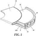
Figure 2 shows a perspective view of the coupling/removal of a conveyor belt with respect to the projecting substantially flat structure. -
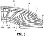
Figure 3 shows a perspective view of a preferred embodiment with the C-shaped profile and in which the projecting substantially flat structure and the lower sub-structure are observed. -
Figure 4 shows a perspective view of the frame with the laminar cover fastened on the projecting substantially flat structure, on which the conveyor belt slides. -
Figure 5 shows a partial perspective view of the frame, with the conveyor belt placed in the service position, and the enveloping cover closed in the working position. -
Figure 6 shows a partial perspective view of the frame, with the conveyor belt partially removed, and the enveloping cover raised. -
Figure 7 shows a detailed perspective view of the retaining pin of the lifting device of the enveloping cover, in the raised position. -
Figure 8 shows a detailed perspective view of the retaining pin of the lifting device of the enveloping cover in the retaining position. -
Figure 9 shows a perspective view of the frame in which the arrangement of the collapsible bearings for supporting and guiding the conveyor belt can be seen. -
Figure 10 shows a perspective view of a curved conveyor belt in which all the elements integrating it, including a plurality of supporting and guiding mechanisms object of the present invention, can be seen. -
Figure 11 shows an exploded perspective view of the different elements comprised in the supporting and of guiding mechanism. -
Figure 12 shows a partial radial section of the curved conveyor belt in which the outer placement of the supporting and guiding assembly on the chassis can be seen, with the outgoing and return segments of the conveyor belt duly guided by the respective bearings. -
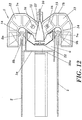
Figure 13 shows a central longitudinal section of the supporting and guiding mechanism, in which the location of the bearings and their accessibility from the exterior can be seen. -
Figure 14 shows a central longitudinal section similar to the previous one, in which the area of the location of the articulation point of the side extensions has been depicted. -
Figure 15 shows a sequence of the supporting and guiding mechanism in its three operating positions, with its respective detailed views of the slide device for the sequential blocking thereof. -
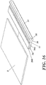
Figure 16 shows a perspective view of a segment of the perimetric guiding profile of the conveyor belts in which the elastic area and the axial hole of the protrusion can be seen. -
Figure 17 shows a cross-section of an embodiment of the profile, with the elastic segment duly sized. -
Figure 18 shows a cross-section of the profile in which the guiding bearings have been depicted to show their operation. -
Figure 19 shows a perspective view of the conveyor belt, with the perimetric profile duly assembled, in which its geometric configuration can be seen. - In view of the discussed figures, it can be observed how a preferred embodiment of the frame (1) for conveyor belts (2) object of invention is described; wherein said frame (1) comprises
a base element (1a),
a pair of rollers (3) wherein one of them is driven by means of an electric motor (4)
a plurality of upper transverse elements (32a) and a plurality of lower transverse elements (32b) located perpendicular to the direction of movement at each point of said conveyor belt (2) and at two height levels,
a plurality of vertical elements (31) coupled respectively at the end of each pair of transverse elements (32a, 32b), each pair located in one and the same vertical plane such that it defines a C-shaped sub-structure open at one of its ends through which said at least one conveyor belt (2) can be introduced/removed, wherein the upper transverse elements (32a) coupled at the upper end of said vertical elements (31) allow the sliding of said conveyor belt (2) over them and define a substantially flat structure (33a),
and wherein the lower transverse elements (32b) coupled at the lower end of said vertical elements (31) allow supporting the sliding of said conveyor belt (2) over them and define a lower sub-structure (33b). - Wherein said substantially flat structure (33a) comprises a laminar cover (34) on which said conveyor belt (2) slides.
- And wherein an enveloping cover (35) is located on an upper side of the substantially flat structure (33a), such that the enveloping cover (35) comprises a lifting device for said enveloping cover (35), allowing the placement/removal of said conveyor belt (2).
- The lifting device comprises a plurality of springs (36) coupled on one hand to the upper part of the substantially flat structure (33a) and on the other hand to the enveloping cover (35), and
a plurality of retaining pins (37) of the plurality of springs (36) which allow blocking/unblocking said springs. - The retaining pins (37) comprise an inclined side flange (41), which pin penetrates the frame through a corresponding hole (42) provided with a notch (43), such that it allows the passage of the pin (37) and can pass through said notch (43) for the subsequent retention. Thus, by pressing on the enveloping cover (35), each pin (37) is introduced in its respective hole (42), and by rotating them through their outer head (44), the enveloping cover (35) is fastened against said frame (1).
- Additionally the lower sub-structure (33b) comprises a plurality of bearings (38) which are coupled to a plurality of arms (39) respectively comprising a rotating shaft (40); and wherein said arms (39) are collapsible with respect to an axis of rotation allowing the handling of said conveyor belt (2).
- The lower sub-structure (33b) comprises a plurality of holes (25) intended for the coupling of supporting elements for the frame, such supporting elements being able to be, for example, supporting legs (19) for support on the floor.
- Additionally, at the ends of the frame (1), the vertical elements (31) together with the upper and lower transverse elements (32a, 32b), there is coupled at least one stringer (45) with a geometric configuration according to the geometry of the segment of said conveyor belt (2).
- Based on the C-shaped configuration, the vertical elements (31), attaching each upper transverse element (32a) with each lower transverse element (32b), comprise two parallel parts (46a, 46b) between which there is arranged a bracket (47) in the upper area, and a lower flat bar (48) in the lower area.
- Complementarily, a supporting and guiding mechanism (5) comprises a central fastening base (6) coupled to the rear part of the frame (1), wherein said central fastening base (6) comprises two inclined surfaces (17) convergent towards said frame (1) and perpendicular to a perimetric guiding profile, wherein two central bearings (8b, 9b) are coupled to said inclined surfaces (17) in the area opposite the frame (1), such that they allow their viewing and handling from the exterior, and
two side extensions (7a, 7b) which are pivoting with respect to the central fastening base (6), wherein each side extension (7a, 7b) has coupled thereto an outer bearing (8a, 9a) such that: - a pair of upper bearings (8a, 8b) is formed by a central bearing (8b) and an upper bearing (8a) closer to a side extension (7a), and
- a pair of lower bearings (9a, 9b) is formed by a central bearing (9b) and an upper bearing (9a) closer to the other side extension (7b),each pair of bearings (8a, 8b) (9a, 9b) being located symmetrically with respect to said conveyor belt (2).
- Each side extension (7a, 7b) comprises two curved flat elements (12) parallel to one another, attached by means of an attachment element (13) located at ends of both curved elements (12) farthest from the central fastening base (6), such that each outer bearing (8a, 9a) is coupled at an outer surface (11) to each attachment element (13) which allows its viewing and handling from the outer area opposite the frame (1).
- Additionally, each side extension (7a, 7b) is articulated at articulation points (16) located at ends (15) of both curved elements (12) closest to the central fastening base (6) such that each side extension (7a, 7b) can pivot with respect to the central fastening base (6) and can be removed when the operator wishes to do so.
- Each supporting and guiding mechanism (5) comprises means for fixing the blocking in a determined position of the side extensions (7a, 7b) with respect to the central fastening base (6); wherein the means for the positioning and blocking comprise a slide device (20) which positions and blocks the side extensions (7a, 7b) in three operating positions with respect to the central fastening base (6):
- a) a first position in which both side extensions (7a, 7b) can freely pivot,
- b) a second position in which one of the side extensions (7a, 7b) is blocked in the service position and the other one can freely pivot, and
- c) a third position in which the two side extensions (7a, 7b) are blocked in the service position.
- And the slide device (20) comprises a part having a U-shaped geometry located coplanar with respect to a larger surface of said at least one conveyor belt (2) such that
side branches (21) of the slide device (20) are coupled to the central fastening base (6) through cavities (22) shaped in said central fastening base (6), a base branch (10) of the slide device (20) is located such that it allows the operator to handle it from the exterior and define the three operating positions, and each side branch (21) of the slide device (20) comprises two holes (23) for the coupling of the side extensions (7a, 7b), wherein two first holes (23a) corresponding to a side extension (7a, 7b) comprise a greater length with respect to the other two second holes (23b) corresponding to the other side extension (7a, 7b), such that it allows the sequential blocking of the side extensions (7a, 7b) defined in operating positions a) and b). - A perimetric guiding profile comprises a protrusion (14) on which the respective pairs of bearings (8a, 8b) (9a, 9b) contact; and wherein said protrusion (14) comprises a symmetrical through hole (28) with respect to a transverse axis of symmetry (29) of said at least one perimetric guiding profile,
an elastic area (27) located after said protrusion (14),
a U-shaped extension (26) located after said elastic area (27) and wherein the perimetric edge of a conveyor belt (2) is coupled at said extension (26); wherein the U-shaped extension (26) comprises two branches (26a, 26b) inclined with respect to one another, which allows securing the perimetric edge of said conveyor belt (2). - The elastic area (27) comprises a segment having a length equal to or greater than the equivalent mean thickness of said segment, the length of the segment of elastic area (27) being comprised between 5 and 30 mm.
- Finally, the area existing between said protrusion (14) and the elastic area (27) comprises respective grooves (30) defining a contact-free space between the bearings (8a, 8b, 9a, 9b) and the elastic area (27), such that the bearings (8a, 8b, 9a, 9b) do not come into contact with said elastic area (27).
- In view of this description and set of drawings, the person skilled in the art could understand that the embodiments of the invention which have been described can be combined in many ways within the object of the invention. The invention has been described according to several preferred embodiments thereof, but it will be evident for the person skilled in the art that many variations can be introduced in said preferred embodiments without exceeding the object of the claimed invention.
Claims (6)
- Frame (1) for conveyor belts (2) comprising at least one base element (1a), and
at least one substantially flat structure (33a) supported by said at least one base element (1a);
wherein said at least one substantially flat structure (33a) is projecting with respect to said at least one base element (1a) and is open on one of its sides through which said at least one conveyor belt (2) can be introduced/removed, and wherein said at least one conveyor belt (2) is close to at least one of the flat faces of said at least one substantially flat structure (33a) in the service position,
wherein the frame comprises a plurality of upper transverse elements (32a) and a plurality of lower transverse elements (32b) located perpendicular to the direction of movement at each point of said conveyor belt (2) and at two height levels,
a plurality of vertical elements (31) coupled respectively at the end of each pair of transverse elements (32a, 32b), located in one and the same vertical plane such that they define a C-shaped sub-structure open at one of its ends through which said at least one conveyor belt (2) can be introduced/removed,
wherein the upper transverse elements (32a) coupled at the upper end of said vertical elements (31) allow the sliding of said at least one conveyor belt (2) over them and define the substantially flat structure (33a),
and wherein the lower transverse elements (32b) coupled at the lower end of said vertical elements allow supporting the sliding of said at least one conveyor belt (2) over them and define a lower sub-structure (33b),
characterized in that at least one enveloping cover (35) is located on an upper side of the substantially flat structure (33a),
and wherein said at least one enveloping cover (35) comprises a lifting device for said at least one enveloping cover (35), allowing the placement/removal of said at least one conveyor belt (2) without needing to remove said at least one enveloping cover (35). - Frame (1) according to claim 1, characterized in that said substantially flat structure (33a) comprises at least one laminar cover (34) on which said conveyor belt (2) slides.
- Frame (1) according to claim 1 or 2, characterized in that the lower sub-structure (33b) comprises a plurality of bearings (38).
- Frame (1) according to claim 3, characterized in that the bearings (38) are coupled to a plurality of arms (39) respectively comprising a rotating shaft (40); and wherein said arms (39) are collapsible with respect to an axis of rotation, allowing the handling of said conveyor belt (2).
- Frame (1) according to any of the previous claims, characterized in that it comprises at least one supporting and guiding mechanism (5) linked to said frame (1), wherein each supporting and guiding mechanism (5) has coupled thereto at least one pair of bearings (8, 9), such that in a service position of the supporting and guiding assembly, in the two bearings (8a, 8b, 9a, 9b) of a pair of bearings (8, 9) their axes of rotation are convergent towards the frame (1) and perpendicular to a perimetric guiding profile.
- Frame (1) according to claim 5, characterized in that said bearings (8a, 8b, 9a, 9b) are coupled to each supporting and guiding mechanism (5) on an inner side, close to the frame (1), such that said bearings (8a, 8b, 9a, 9b) allow their viewing and handling from an outer side, far from the frame (1).
Applications Claiming Priority (5)
| Application Number | Priority Date | Filing Date | Title |
|---|---|---|---|
| EP09165764A EP2275364A1 (en) | 2009-07-17 | 2009-07-17 | Guide means fixed to curved conveyor belts |
| EP09165774A EP2275365A1 (en) | 2009-07-17 | 2009-07-17 | Support and guiding system for curved conveyor belts |
| EP09179053A EP2332860A1 (en) | 2009-12-14 | 2009-12-14 | Self- supporting frame for removable conveyor belts |
| EP10799475.8A EP2455308B1 (en) | 2009-07-17 | 2010-07-15 | Assembly for supporting and guiding conveyor belts |
| PCT/ES2010/070491 WO2011007040A2 (en) | 2009-07-17 | 2010-07-15 | Assembly for supporting and guiding conveyor belts |
Related Parent Applications (1)
| Application Number | Title | Priority Date | Filing Date |
|---|---|---|---|
| EP10799475.8A Division EP2455308B1 (en) | 2009-07-17 | 2010-07-15 | Assembly for supporting and guiding conveyor belts |
Publications (2)
| Publication Number | Publication Date |
|---|---|
| EP3398884A1 EP3398884A1 (en) | 2018-11-07 |
| EP3398884B1 true EP3398884B1 (en) | 2021-03-03 |
Family
ID=43449894
Family Applications (2)
| Application Number | Title | Priority Date | Filing Date |
|---|---|---|---|
| EP18180401.4A Active EP3398884B1 (en) | 2009-07-17 | 2010-07-15 | Frame for conveyor belts |
| EP10799475.8A Active EP2455308B1 (en) | 2009-07-17 | 2010-07-15 | Assembly for supporting and guiding conveyor belts |
Family Applications After (1)
| Application Number | Title | Priority Date | Filing Date |
|---|---|---|---|
| EP10799475.8A Active EP2455308B1 (en) | 2009-07-17 | 2010-07-15 | Assembly for supporting and guiding conveyor belts |
Country Status (6)
| Country | Link |
|---|---|
| US (1) | US8997976B2 (en) |
| EP (2) | EP3398884B1 (en) |
| CN (1) | CN102625774B (en) |
| BR (1) | BR112012001158B1 (en) |
| ES (2) | ES2867861T3 (en) |
| WO (1) | WO2011007040A2 (en) |
Families Citing this family (10)
| Publication number | Priority date | Publication date | Assignee | Title |
|---|---|---|---|---|
| ITMI20121515A1 (en) * | 2012-09-14 | 2014-03-15 | Rexnord Marbett Srl | APPARATUS FOR ASSISTING THE SLIDING OF A CHAIN |
| NL2009721C2 (en) * | 2012-10-29 | 2014-05-01 | Rexnord Flattop Europe Bv | FINAL DRIVE FOR A TRANSPORTER, TRANSPORTED WITH AN END DRIVE, AND DRIVE GEAR FOR AN END DRIVE. |
| CN104261051A (en) * | 2014-09-16 | 2015-01-07 | 潍坊盛丰包装制品有限公司 | Ball type clamp for conveying belt |
| CN104355040A (en) * | 2014-10-13 | 2015-02-18 | 苏州艾斯特工业设备有限公司 | 90-degree turning belt conveyer |
| CN106494822B (en) * | 2016-11-28 | 2019-05-10 | 浙江品创知识产权服务有限公司 | A kind of adjustable turning conveying equipment of angle of turn |
| CN107185862B (en) * | 2017-07-14 | 2019-05-28 | 安徽中科光电色选机械有限公司 | Conveying device based on color sorting machine equipment |
| CN109969686B (en) * | 2019-05-15 | 2021-03-16 | 枣庄学院 | Automatic conveying device of production line |
| CN112758608B (en) * | 2019-11-05 | 2022-11-18 | 隆回县好树衣柜制造有限公司 | Transmission device with protection function for furniture production conveyor belt |
| CN112678418B (en) * | 2020-12-31 | 2022-08-23 | 南通嘉浩自动化设备有限公司 | Turning roller line mechanism and application process thereof |
| IT202200007400A1 (en) * | 2022-04-13 | 2023-10-13 | Mech Sistemi S R L | CURVED CONVEYOR BELT |
Family Cites Families (13)
| Publication number | Priority date | Publication date | Assignee | Title |
|---|---|---|---|---|
| DE3822824A1 (en) | 1988-07-06 | 1990-02-01 | Transnorm System Gmbh | BELT CURVE FOR CONVEYOR BELT SYSTEMS |
| FR2663309B1 (en) * | 1990-06-15 | 1994-06-17 | Rozier Jean Michel | CONVEYOR WITH CONVEYOR BELT WITH RAPID DISASSEMBLY AND REASSEMBLY OF THE BELT. |
| IT227686Y1 (en) * | 1992-11-20 | 1997-12-15 | Hitech Systems Srl | CONVEYOR FOR THE DISPOSAL OF GENERIC PRODUCTS WITH PACKAGING OR BOXING MACHINES |
| US5394977A (en) * | 1993-07-08 | 1995-03-07 | Portec, Inc. | Apparatus and method for use in replacing conveyor belts |
| DE4412931A1 (en) | 1994-04-15 | 1995-10-19 | Transnorm System Gmbh | Curve guide for conveyor |
| NL9402081A (en) | 1994-12-09 | 1996-07-01 | Vanderlande Ind Nederland | Transport device. |
| DE29502064U1 (en) | 1995-02-10 | 1995-06-01 | Transnorm System Gmbh | Cam belt conveyor |
| DE19535757A1 (en) | 1995-09-26 | 1997-03-27 | Transnorm System Gmbh | Flat conveyor belt transporter system |
| US5722531A (en) * | 1996-02-13 | 1998-03-03 | Mannesmann Dematic Rapistan Corp. | Belt turn conveyor |
| JPH10181821A (en) * | 1996-12-21 | 1998-07-07 | Temusu:Kk | Curved conveyor |
| US7232030B2 (en) | 2004-11-24 | 2007-06-19 | Transnorm System Inc. | Quick release holder for a beading of a conveyor belt and method of using quick release holder |
| DE102006024536C5 (en) * | 2006-05-23 | 2012-10-18 | Logcomp Gmbh | Curve |
| US7497326B2 (en) | 2006-08-15 | 2009-03-03 | Transnorm System, Inc. | Pivotable support for a conveyor and method of replacing a damaged conveyor belt |
-
2010
- 2010-07-15 ES ES18180401T patent/ES2867861T3/en active Active
- 2010-07-15 ES ES10799475.8T patent/ES2685897T3/en active Active
- 2010-07-15 EP EP18180401.4A patent/EP3398884B1/en active Active
- 2010-07-15 WO PCT/ES2010/070491 patent/WO2011007040A2/en active Application Filing
- 2010-07-15 CN CN201080037779.4A patent/CN102625774B/en active Active
- 2010-07-15 BR BR112012001158A patent/BR112012001158B1/en active IP Right Grant
- 2010-07-15 EP EP10799475.8A patent/EP2455308B1/en active Active
- 2010-07-15 US US13/384,409 patent/US8997976B2/en active Active
Non-Patent Citations (1)
| Title |
|---|
| None * |
Also Published As
| Publication number | Publication date |
|---|---|
| CN102625774A (en) | 2012-08-01 |
| BR112012001158A2 (en) | 2018-03-13 |
| US8997976B2 (en) | 2015-04-07 |
| BR112012001158B1 (en) | 2020-04-07 |
| WO2011007040A3 (en) | 2011-07-21 |
| WO2011007040A2 (en) | 2011-01-20 |
| US20120125740A1 (en) | 2012-05-24 |
| EP2455308A4 (en) | 2016-12-28 |
| EP2455308A2 (en) | 2012-05-23 |
| EP3398884A1 (en) | 2018-11-07 |
| ES2867861T3 (en) | 2021-10-21 |
| CN102625774B (en) | 2016-03-16 |
| WO2011007040A8 (en) | 2011-11-10 |
| ES2685897T3 (en) | 2018-10-15 |
| EP2455308B1 (en) | 2018-07-04 |
Similar Documents
| Publication | Publication Date | Title |
|---|---|---|
| EP3398884B1 (en) | Frame for conveyor belts | |
| EP2858928B1 (en) | Roller-way conveyor | |
| US20090242360A1 (en) | End protector link for conveyor chain | |
| US11299359B2 (en) | Lapper assembly | |
| US10899570B2 (en) | Systems, devices and methods for receiving an item | |
| KR20060081662A (en) | Door interlocking system | |
| CN104696459A (en) | Chain drive unit | |
| ITBO20080259A1 (en) | ROTATING CONVEYOR FOR OPERATING MACHINES TO MANIPULATE CONTAINERS, IN PARTICULAR FOR CAPPING MACHINES, AND CAPPING MACHINE PROVIDED WITH THIS ROTATING CONVEYOR. | |
| EP3145841A1 (en) | Sorting system having cover plates closing gaps between support structures | |
| EP2275365A1 (en) | Support and guiding system for curved conveyor belts | |
| US20060054472A1 (en) | End protector link for conveyor chain | |
| WO2017131508A1 (en) | Former holder locking mechanism | |
| CN105270829A (en) | Belt conveyer | |
| KR101166934B1 (en) | Semi-Auto APC door device | |
| KR101143822B1 (en) | Apparatus to load glass panels | |
| KR20200137823A (en) | Adhesive apparatus of tape for box package | |
| EP2762411B1 (en) | Thermoforming machine | |
| CN107580667B (en) | Protective housing for a test device, measuring device or production device | |
| EP2554931A1 (en) | Support and movement equipment | |
| JP2015020842A (en) | Conveyor apparatus | |
| JP6284702B2 (en) | Slide shoe sliding abnormality detection device | |
| CN207952174U (en) | Attachment device and cleaning machine | |
| KR200270502Y1 (en) | Carriage roller structure for gantry robot | |
| JP2021107084A (en) | Crusher | |
| JP2008094533A (en) | Slat conveyor |
Legal Events
| Date | Code | Title | Description |
|---|---|---|---|
| PUAI | Public reference made under article 153(3) epc to a published international application that has entered the european phase |
Free format text: ORIGINAL CODE: 0009012 |
|
| STAA | Information on the status of an ep patent application or granted ep patent |
Free format text: STATUS: THE APPLICATION HAS BEEN PUBLISHED |
|
| AC | Divisional application: reference to earlier application |
Ref document number: 2455308 Country of ref document: EP Kind code of ref document: P |
|
| AK | Designated contracting states |
Kind code of ref document: A1 Designated state(s): AL AT BE BG CH CY CZ DE DK EE ES FI FR GB GR HR HU IE IS IT LI LT LU LV MC MK MT NL NO PL PT RO SE SI SK SM TR |
|
| STAA | Information on the status of an ep patent application or granted ep patent |
Free format text: STATUS: REQUEST FOR EXAMINATION WAS MADE |
|
| 17P | Request for examination filed |
Effective date: 20190506 |
|
| RBV | Designated contracting states (corrected) |
Designated state(s): AL AT BE BG CH CY CZ DE DK EE ES FI FR GB GR HR HU IE IS IT LI LT LU LV MC MK MT NL NO PL PT RO SE SI SK SM TR |
|
| GRAP | Despatch of communication of intention to grant a patent |
Free format text: ORIGINAL CODE: EPIDOSNIGR1 |
|
| STAA | Information on the status of an ep patent application or granted ep patent |
Free format text: STATUS: GRANT OF PATENT IS INTENDED |
|
| INTG | Intention to grant announced |
Effective date: 20200622 |
|
| GRAJ | Information related to disapproval of communication of intention to grant by the applicant or resumption of examination proceedings by the epo deleted |
Free format text: ORIGINAL CODE: EPIDOSDIGR1 |
|
| STAA | Information on the status of an ep patent application or granted ep patent |
Free format text: STATUS: REQUEST FOR EXAMINATION WAS MADE |
|
| GRAP | Despatch of communication of intention to grant a patent |
Free format text: ORIGINAL CODE: EPIDOSNIGR1 |
|
| STAA | Information on the status of an ep patent application or granted ep patent |
Free format text: STATUS: GRANT OF PATENT IS INTENDED |
|
| INTC | Intention to grant announced (deleted) | ||
| INTG | Intention to grant announced |
Effective date: 20201103 |
|
| RIN1 | Information on inventor provided before grant (corrected) |
Inventor name: GAVALDA MONEDERO, JORDI |
|
| GRAS | Grant fee paid |
Free format text: ORIGINAL CODE: EPIDOSNIGR3 |
|
| STAA | Information on the status of an ep patent application or granted ep patent |
Free format text: STATUS: GRANT OF PATENT IS INTENDED |
|
| GRAA | (expected) grant |
Free format text: ORIGINAL CODE: 0009210 |
|
| STAA | Information on the status of an ep patent application or granted ep patent |
Free format text: STATUS: THE PATENT HAS BEEN GRANTED |
|
| AC | Divisional application: reference to earlier application |
Ref document number: 2455308 Country of ref document: EP Kind code of ref document: P |
|
| AK | Designated contracting states |
Kind code of ref document: B1 Designated state(s): AL AT BE BG CH CY CZ DE DK EE ES FI FR GB GR HR HU IE IS IT LI LT LU LV MC MK MT NL NO PL PT RO SE SI SK SM TR |
|
| REG | Reference to a national code |
Ref country code: GB Ref legal event code: FG4D |
|
| REG | Reference to a national code |
Ref country code: AT Ref legal event code: REF Ref document number: 1366987 Country of ref document: AT Kind code of ref document: T Effective date: 20210315 Ref country code: CH Ref legal event code: EP |
|
| REG | Reference to a national code |
Ref country code: DE Ref legal event code: R096 Ref document number: 602010066553 Country of ref document: DE |
|
| REG | Reference to a national code |
Ref country code: IE Ref legal event code: FG4D |
|
| REG | Reference to a national code |
Ref country code: NL Ref legal event code: FP |
|
| REG | Reference to a national code |
Ref country code: LT Ref legal event code: MG9D |
|
| PG25 | Lapsed in a contracting state [announced via postgrant information from national office to epo] |
Ref country code: LT Free format text: LAPSE BECAUSE OF FAILURE TO SUBMIT A TRANSLATION OF THE DESCRIPTION OR TO PAY THE FEE WITHIN THE PRESCRIBED TIME-LIMIT Effective date: 20210303 Ref country code: NO Free format text: LAPSE BECAUSE OF FAILURE TO SUBMIT A TRANSLATION OF THE DESCRIPTION OR TO PAY THE FEE WITHIN THE PRESCRIBED TIME-LIMIT Effective date: 20210603 Ref country code: BG Free format text: LAPSE BECAUSE OF FAILURE TO SUBMIT A TRANSLATION OF THE DESCRIPTION OR TO PAY THE FEE WITHIN THE PRESCRIBED TIME-LIMIT Effective date: 20210603 Ref country code: HR Free format text: LAPSE BECAUSE OF FAILURE TO SUBMIT A TRANSLATION OF THE DESCRIPTION OR TO PAY THE FEE WITHIN THE PRESCRIBED TIME-LIMIT Effective date: 20210303 Ref country code: FI Free format text: LAPSE BECAUSE OF FAILURE TO SUBMIT A TRANSLATION OF THE DESCRIPTION OR TO PAY THE FEE WITHIN THE PRESCRIBED TIME-LIMIT Effective date: 20210303 Ref country code: GR Free format text: LAPSE BECAUSE OF FAILURE TO SUBMIT A TRANSLATION OF THE DESCRIPTION OR TO PAY THE FEE WITHIN THE PRESCRIBED TIME-LIMIT Effective date: 20210604 |
|
| REG | Reference to a national code |
Ref country code: AT Ref legal event code: MK05 Ref document number: 1366987 Country of ref document: AT Kind code of ref document: T Effective date: 20210303 |
|
| PG25 | Lapsed in a contracting state [announced via postgrant information from national office to epo] |
Ref country code: LV Free format text: LAPSE BECAUSE OF FAILURE TO SUBMIT A TRANSLATION OF THE DESCRIPTION OR TO PAY THE FEE WITHIN THE PRESCRIBED TIME-LIMIT Effective date: 20210303 Ref country code: PL Free format text: LAPSE BECAUSE OF FAILURE TO SUBMIT A TRANSLATION OF THE DESCRIPTION OR TO PAY THE FEE WITHIN THE PRESCRIBED TIME-LIMIT Effective date: 20210303 Ref country code: SE Free format text: LAPSE BECAUSE OF FAILURE TO SUBMIT A TRANSLATION OF THE DESCRIPTION OR TO PAY THE FEE WITHIN THE PRESCRIBED TIME-LIMIT Effective date: 20210303 |
|
| REG | Reference to a national code |
Ref country code: ES Ref legal event code: FG2A Ref document number: 2867861 Country of ref document: ES Kind code of ref document: T3 Effective date: 20211021 |
|
| PG25 | Lapsed in a contracting state [announced via postgrant information from national office to epo] |
Ref country code: CZ Free format text: LAPSE BECAUSE OF FAILURE TO SUBMIT A TRANSLATION OF THE DESCRIPTION OR TO PAY THE FEE WITHIN THE PRESCRIBED TIME-LIMIT Effective date: 20210303 Ref country code: EE Free format text: LAPSE BECAUSE OF FAILURE TO SUBMIT A TRANSLATION OF THE DESCRIPTION OR TO PAY THE FEE WITHIN THE PRESCRIBED TIME-LIMIT Effective date: 20210303 Ref country code: AT Free format text: LAPSE BECAUSE OF FAILURE TO SUBMIT A TRANSLATION OF THE DESCRIPTION OR TO PAY THE FEE WITHIN THE PRESCRIBED TIME-LIMIT Effective date: 20210303 Ref country code: SM Free format text: LAPSE BECAUSE OF FAILURE TO SUBMIT A TRANSLATION OF THE DESCRIPTION OR TO PAY THE FEE WITHIN THE PRESCRIBED TIME-LIMIT Effective date: 20210303 |
|
| PG25 | Lapsed in a contracting state [announced via postgrant information from national office to epo] |
Ref country code: PT Free format text: LAPSE BECAUSE OF FAILURE TO SUBMIT A TRANSLATION OF THE DESCRIPTION OR TO PAY THE FEE WITHIN THE PRESCRIBED TIME-LIMIT Effective date: 20210705 Ref country code: SK Free format text: LAPSE BECAUSE OF FAILURE TO SUBMIT A TRANSLATION OF THE DESCRIPTION OR TO PAY THE FEE WITHIN THE PRESCRIBED TIME-LIMIT Effective date: 20210303 Ref country code: RO Free format text: LAPSE BECAUSE OF FAILURE TO SUBMIT A TRANSLATION OF THE DESCRIPTION OR TO PAY THE FEE WITHIN THE PRESCRIBED TIME-LIMIT Effective date: 20210303 Ref country code: IS Free format text: LAPSE BECAUSE OF FAILURE TO SUBMIT A TRANSLATION OF THE DESCRIPTION OR TO PAY THE FEE WITHIN THE PRESCRIBED TIME-LIMIT Effective date: 20210703 |
|
| REG | Reference to a national code |
Ref country code: DE Ref legal event code: R097 Ref document number: 602010066553 Country of ref document: DE |
|
| PLBE | No opposition filed within time limit |
Free format text: ORIGINAL CODE: 0009261 |
|
| STAA | Information on the status of an ep patent application or granted ep patent |
Free format text: STATUS: NO OPPOSITION FILED WITHIN TIME LIMIT |
|
| PG25 | Lapsed in a contracting state [announced via postgrant information from national office to epo] |
Ref country code: DK Free format text: LAPSE BECAUSE OF FAILURE TO SUBMIT A TRANSLATION OF THE DESCRIPTION OR TO PAY THE FEE WITHIN THE PRESCRIBED TIME-LIMIT Effective date: 20210303 Ref country code: AL Free format text: LAPSE BECAUSE OF FAILURE TO SUBMIT A TRANSLATION OF THE DESCRIPTION OR TO PAY THE FEE WITHIN THE PRESCRIBED TIME-LIMIT Effective date: 20210303 |
|
| 26N | No opposition filed |
Effective date: 20211206 |
|
| PG25 | Lapsed in a contracting state [announced via postgrant information from national office to epo] |
Ref country code: SI Free format text: LAPSE BECAUSE OF FAILURE TO SUBMIT A TRANSLATION OF THE DESCRIPTION OR TO PAY THE FEE WITHIN THE PRESCRIBED TIME-LIMIT Effective date: 20210303 |
|
| REG | Reference to a national code |
Ref country code: CH Ref legal event code: PL |
|
| PG25 | Lapsed in a contracting state [announced via postgrant information from national office to epo] |
Ref country code: MC Free format text: LAPSE BECAUSE OF FAILURE TO SUBMIT A TRANSLATION OF THE DESCRIPTION OR TO PAY THE FEE WITHIN THE PRESCRIBED TIME-LIMIT Effective date: 20210303 |
|
| REG | Reference to a national code |
Ref country code: BE Ref legal event code: MM Effective date: 20210731 |
|
| PG25 | Lapsed in a contracting state [announced via postgrant information from national office to epo] |
Ref country code: LI Free format text: LAPSE BECAUSE OF NON-PAYMENT OF DUE FEES Effective date: 20210731 Ref country code: IT Free format text: LAPSE BECAUSE OF FAILURE TO SUBMIT A TRANSLATION OF THE DESCRIPTION OR TO PAY THE FEE WITHIN THE PRESCRIBED TIME-LIMIT Effective date: 20210303 Ref country code: CH Free format text: LAPSE BECAUSE OF NON-PAYMENT OF DUE FEES Effective date: 20210731 |
|
| PG25 | Lapsed in a contracting state [announced via postgrant information from national office to epo] |
Ref country code: IS Free format text: LAPSE BECAUSE OF FAILURE TO SUBMIT A TRANSLATION OF THE DESCRIPTION OR TO PAY THE FEE WITHIN THE PRESCRIBED TIME-LIMIT Effective date: 20210703 Ref country code: LU Free format text: LAPSE BECAUSE OF NON-PAYMENT OF DUE FEES Effective date: 20210715 |
|
| PG25 | Lapsed in a contracting state [announced via postgrant information from national office to epo] |
Ref country code: IE Free format text: LAPSE BECAUSE OF NON-PAYMENT OF DUE FEES Effective date: 20210715 Ref country code: BE Free format text: LAPSE BECAUSE OF NON-PAYMENT OF DUE FEES Effective date: 20210731 |
|
| PG25 | Lapsed in a contracting state [announced via postgrant information from national office to epo] |
Ref country code: CY Free format text: LAPSE BECAUSE OF FAILURE TO SUBMIT A TRANSLATION OF THE DESCRIPTION OR TO PAY THE FEE WITHIN THE PRESCRIBED TIME-LIMIT Effective date: 20210303 |
|
| P01 | Opt-out of the competence of the unified patent court (upc) registered |
Effective date: 20230525 |
|
| PG25 | Lapsed in a contracting state [announced via postgrant information from national office to epo] |
Ref country code: HU Free format text: LAPSE BECAUSE OF FAILURE TO SUBMIT A TRANSLATION OF THE DESCRIPTION OR TO PAY THE FEE WITHIN THE PRESCRIBED TIME-LIMIT; INVALID AB INITIO Effective date: 20100715 |
|
| PGFP | Annual fee paid to national office [announced via postgrant information from national office to epo] |
Ref country code: NL Payment date: 20230719 Year of fee payment: 14 |
|
| PGFP | Annual fee paid to national office [announced via postgrant information from national office to epo] |
Ref country code: GB Payment date: 20230721 Year of fee payment: 14 Ref country code: ES Payment date: 20230926 Year of fee payment: 14 |
|
| PGFP | Annual fee paid to national office [announced via postgrant information from national office to epo] |
Ref country code: FR Payment date: 20230726 Year of fee payment: 14 Ref country code: DE Payment date: 20230719 Year of fee payment: 14 |
|
| PG25 | Lapsed in a contracting state [announced via postgrant information from national office to epo] |
Ref country code: MK Free format text: LAPSE BECAUSE OF FAILURE TO SUBMIT A TRANSLATION OF THE DESCRIPTION OR TO PAY THE FEE WITHIN THE PRESCRIBED TIME-LIMIT Effective date: 20210303 |