EP3398779B1 - Düsenanordnung für biologischen drucker sowie biologischer drucker - Google Patents
Düsenanordnung für biologischen drucker sowie biologischer drucker Download PDFInfo
- Publication number
- EP3398779B1 EP3398779B1 EP15911815.7A EP15911815A EP3398779B1 EP 3398779 B1 EP3398779 B1 EP 3398779B1 EP 15911815 A EP15911815 A EP 15911815A EP 3398779 B1 EP3398779 B1 EP 3398779B1
- Authority
- EP
- European Patent Office
- Prior art keywords
- spray head
- flow channel
- bioprinter
- printing unit
- outlet
- Prior art date
- Legal status (The legal status is an assumption and is not a legal conclusion. Google has not performed a legal analysis and makes no representation as to the accuracy of the status listed.)
- Active
Links
Images
Classifications
-
- B—PERFORMING OPERATIONS; TRANSPORTING
- B29—WORKING OF PLASTICS; WORKING OF SUBSTANCES IN A PLASTIC STATE IN GENERAL
- B29C—SHAPING OR JOINING OF PLASTICS; SHAPING OF MATERIAL IN A PLASTIC STATE, NOT OTHERWISE PROVIDED FOR; AFTER-TREATMENT OF THE SHAPED PRODUCTS, e.g. REPAIRING
- B29C64/00—Additive manufacturing, i.e. manufacturing of three-dimensional [3D] objects by additive deposition, additive agglomeration or additive layering, e.g. by 3D printing, stereolithography or selective laser sintering
- B29C64/20—Apparatus for additive manufacturing; Details thereof or accessories therefor
- B29C64/205—Means for applying layers
- B29C64/209—Heads; Nozzles
-
- A—HUMAN NECESSITIES
- A61—MEDICAL OR VETERINARY SCIENCE; HYGIENE
- A61F—FILTERS IMPLANTABLE INTO BLOOD VESSELS; PROSTHESES; DEVICES PROVIDING PATENCY TO, OR PREVENTING COLLAPSING OF, TUBULAR STRUCTURES OF THE BODY, e.g. STENTS; ORTHOPAEDIC, NURSING OR CONTRACEPTIVE DEVICES; FOMENTATION; TREATMENT OR PROTECTION OF EYES OR EARS; BANDAGES, DRESSINGS OR ABSORBENT PADS; FIRST-AID KITS
- A61F2/00—Filters implantable into blood vessels; Prostheses, i.e. artificial substitutes or replacements for parts of the body; Appliances for connecting them with the body; Devices providing patency to, or preventing collapsing of, tubular structures of the body, e.g. stents
- A61F2/02—Prostheses implantable into the body
-
- B—PERFORMING OPERATIONS; TRANSPORTING
- B05—SPRAYING OR ATOMISING IN GENERAL; APPLYING FLUENT MATERIALS TO SURFACES, IN GENERAL
- B05B—SPRAYING APPARATUS; ATOMISING APPARATUS; NOZZLES
- B05B7/00—Spraying apparatus for discharge of liquids or other fluent materials from two or more sources, e.g. of liquid and air, of powder and gas
- B05B7/02—Spray pistols; Apparatus for discharge
- B05B7/04—Spray pistols; Apparatus for discharge with arrangements for mixing liquids or other fluent materials before discharge
- B05B7/0408—Spray pistols; Apparatus for discharge with arrangements for mixing liquids or other fluent materials before discharge with arrangements for mixing two or more liquids
-
- B—PERFORMING OPERATIONS; TRANSPORTING
- B33—ADDITIVE MANUFACTURING TECHNOLOGY
- B33Y—ADDITIVE MANUFACTURING, i.e. MANUFACTURING OF THREE-DIMENSIONAL [3-D] OBJECTS BY ADDITIVE DEPOSITION, ADDITIVE AGGLOMERATION OR ADDITIVE LAYERING, e.g. BY 3-D PRINTING, STEREOLITHOGRAPHY OR SELECTIVE LASER SINTERING
- B33Y30/00—Apparatus for additive manufacturing; Details thereof or accessories therefor
-
- A—HUMAN NECESSITIES
- A61—MEDICAL OR VETERINARY SCIENCE; HYGIENE
- A61F—FILTERS IMPLANTABLE INTO BLOOD VESSELS; PROSTHESES; DEVICES PROVIDING PATENCY TO, OR PREVENTING COLLAPSING OF, TUBULAR STRUCTURES OF THE BODY, e.g. STENTS; ORTHOPAEDIC, NURSING OR CONTRACEPTIVE DEVICES; FOMENTATION; TREATMENT OR PROTECTION OF EYES OR EARS; BANDAGES, DRESSINGS OR ABSORBENT PADS; FIRST-AID KITS
- A61F2/00—Filters implantable into blood vessels; Prostheses, i.e. artificial substitutes or replacements for parts of the body; Appliances for connecting them with the body; Devices providing patency to, or preventing collapsing of, tubular structures of the body, e.g. stents
- A61F2/02—Prostheses implantable into the body
- A61F2/30—Joints
- A61F2/3094—Designing or manufacturing processes
- A61F2002/30985—Designing or manufacturing processes using three dimensional printing [3DP]
-
- B—PERFORMING OPERATIONS; TRANSPORTING
- B05—SPRAYING OR ATOMISING IN GENERAL; APPLYING FLUENT MATERIALS TO SURFACES, IN GENERAL
- B05B—SPRAYING APPARATUS; ATOMISING APPARATUS; NOZZLES
- B05B7/00—Spraying apparatus for discharge of liquids or other fluent materials from two or more sources, e.g. of liquid and air, of powder and gas
- B05B7/0012—Apparatus for achieving spraying before discharge from the apparatus
-
- B—PERFORMING OPERATIONS; TRANSPORTING
- B29—WORKING OF PLASTICS; WORKING OF SUBSTANCES IN A PLASTIC STATE IN GENERAL
- B29C—SHAPING OR JOINING OF PLASTICS; SHAPING OF MATERIAL IN A PLASTIC STATE, NOT OTHERWISE PROVIDED FOR; AFTER-TREATMENT OF THE SHAPED PRODUCTS, e.g. REPAIRING
- B29C64/00—Additive manufacturing, i.e. manufacturing of three-dimensional [3D] objects by additive deposition, additive agglomeration or additive layering, e.g. by 3D printing, stereolithography or selective laser sintering
- B29C64/10—Processes of additive manufacturing
- B29C64/106—Processes of additive manufacturing using only liquids or viscous materials, e.g. depositing a continuous bead of viscous material
-
- B—PERFORMING OPERATIONS; TRANSPORTING
- B41—PRINTING; LINING MACHINES; TYPEWRITERS; STAMPS
- B41J—TYPEWRITERS; SELECTIVE PRINTING MECHANISMS, i.e. MECHANISMS PRINTING OTHERWISE THAN FROM A FORME; CORRECTION OF TYPOGRAPHICAL ERRORS
- B41J2/00—Typewriters or selective printing mechanisms characterised by the printing or marking process for which they are designed
- B41J2/005—Typewriters or selective printing mechanisms characterised by the printing or marking process for which they are designed characterised by bringing liquid or particles selectively into contact with a printing material
- B41J2/01—Ink jet
- B41J2/135—Nozzles
- B41J2/14—Structure thereof only for on-demand ink jet heads
- B41J2/1433—Structure of nozzle plates
-
- B—PERFORMING OPERATIONS; TRANSPORTING
- B41—PRINTING; LINING MACHINES; TYPEWRITERS; STAMPS
- B41J—TYPEWRITERS; SELECTIVE PRINTING MECHANISMS, i.e. MECHANISMS PRINTING OTHERWISE THAN FROM A FORME; CORRECTION OF TYPOGRAPHICAL ERRORS
- B41J2/00—Typewriters or selective printing mechanisms characterised by the printing or marking process for which they are designed
- B41J2/005—Typewriters or selective printing mechanisms characterised by the printing or marking process for which they are designed characterised by bringing liquid or particles selectively into contact with a printing material
- B41J2/01—Ink jet
- B41J2/135—Nozzles
- B41J2/14—Structure thereof only for on-demand ink jet heads
- B41J2002/14475—Structure thereof only for on-demand ink jet heads characterised by nozzle shapes or number of orifices per chamber
Definitions
- the present disclosure relates to the field of bioprinting, and especially relates to a bioprinter spray head assembly and a bioprinter.
- 3D bioprinting refers to the printing of biological materials (including natural biological materials and synthetic biological materials or cellular solutions) into a designed three-dimensional structure through the principles and methods of 3D printing. Differing from those printed by ordinary 3D printing technology, the biological tissues or organs produced by 3D bioprinting technology have certain biological functions and need to provide conditions for the further growth of cells and tissues. Exactly due to the aforementioned characteristics, the 3D bioprinting technology is confronted with many specific technical problems in development.
- the print technique of taking cells as a printing material is referred to as cell three-dimensional printing technology.
- People may utilize cells and biocompatible materials to make bio-ink.
- the spray head moves and sprays the bio-ink, and the movement of the spray head is controlled by a program to print the bio-ink.
- the bio-ink is printed and molded according to a three-dimensionally constructed digital model of a preset target print object.
- CN105167879A provides a spray nozzle with double flow channels.
- the spray nozzle with the double flow channels has the advantages that the two different materials are respectively arranged in the inner flow channel and the outer flow channel by the aid of inner and outer double-flow-channel technologies, accordingly, the spinneret structure with the corresponding material in the center and the other material uniformly arranged on the periphery can be formed by means of squeezing, the central material can be effectively protected, and cell substances in the center of the spray nozzle can be protected when the spray nozzle is applied to 3D (three-dimensional) biological printing; nutrients can be provided, so that the survival rate of printed biological cells can be increased.
- US6267266B1 provides an apparatus for dispensing a small amount of a viscous liquid material onto a substrate.
- the apparatus comprises a housing and piston positioned within the housing and having a lower surface and a flow bore extending therein, the flow bore having an inlet for receiving the viscous liquid material and an outlet.
- the apparatus further includes a compressible dispensing element positioned within the housing below and in liquid tight sealing engagement with the lower surface of the piston and having a passage extending therethrough, the passage having an inlet in liquid communication with the outlet of the flow bore and an outlet.
- the lower surface of the piston is capable of applying a force to compress the dispensing element causing the passage to at least partially close expelling a small amount of the viscous liquid material from the outlet of the passage.
- the apparatus has a nozzle in liquid communication with the outlet of the passage for guiding the small amount of viscous liquid material expelled from the outlet of the passage onto the substrate.
- US5074443A provides an adaptor for liquid dispensing of precisely controlled amounts through an outlet of a liquid filled syringe.
- the adaptor includes a valve shaft extended through an inlet of the syringe, along the syringe and seated against a valve seat assembly at the outlet of the syringe.
- the valve seat assembly and a cylindrical casing cooperatively mount the syringe to a housing assembly.
- a spring within the housing assembly biases the valve shaft to a normally closed position against the valve seat assembly.
- timer actuation of a solenoid within the housing assembly retracts the valve shaft away from the valve seat assembly to an open position to force the pressurized liquid through the outlet and out of the syringe.
- the technical problem solved by the present disclosure is to provide a bioprinter spray head assembly and a bioprinter, which are capable of preventing clogging of the biological printing material.
- the present disclosure provides a bioprinter spray head assembly according to claim 1.
- a fluid print unit serving as a biological printing material is orientedly sprayed through the flow channel by providing an extension rod having an elongated flow channel adjacent to the outlet of the spray head.
- the flow channel can perform an oriented sequence of the fluid printing unit, so as to reduce the possibility of clogging.
- the flow channel is tapered from its inlet to outlet.
- the flow channel is designed in a structural form tapered from its inlet to outlet.
- the fluid printing unit travels progressively in the flow channel, which facilitates raising the flow velocity of the fluid printing unit at the outlet of the flow channel, and further reducing the possibility of its clogging.
- the flow channel has a conical section taken along a flow direction of the fluid printing unit.
- the flow channel is further designed in a conical structural form, which makes a more uniform distribution of the fluid printing unit in the flow channel, and further reduces the possibility of its clogging.
- the conical flow channel is easy to process.
- the outlet of the flow channel is sized to be 1-1.5 times the size of the fluid printing unit.
- the outlet of the flow channel is sized to be 1.2 times the size of the fluid printing unit.
- the size of the outlet of the flow channel is designed in such a structural form as to be 1.2 times the size of the fluid printing unit, which not only facilitates the spray of the fluid printing units in a single row, but also can avoid that the second material wraps the first material in an excessive thickness in the case of ensuring that the first material is not damaged, and facilitate further raising the flow rate of the fluid printing units at the outlet of the flow channel, and ensure a single-row and uniform spray of the fluid sprinting units.
- the inlet of the flow channel is sized to be 2 times the size of the fluid printing unit.
- the size of the inlet of the flow channel is designed in such a structural form as to be multiple times the size of the fluid printing unit.
- a plurality of fluid printing units preferably two fluid printing units, may enter side by side at the inlet of the flow channel.
- an open recess is provided on an end surface of the extension rod adjacent to the spray head.
- An outlet of the open recess communicates with the flow channel, and the spray head extends into the open recess.
- the open recess is tapered toward the flow channel, and a second material flow channel is formed between an outer wall of the spray head and the open recess, forming a chamber between the outlet of the spray head and the outlet of the open recess.
- the second material passing through the second material flow channel wraps a first material sprayed from the spray head in the chamber, so as to form a fluid printing unit.
- a second material flow channel is formed between an outer wall of the spray head and the open recess, and a chamber is formed between the outlet of the spray head and the outlet of the open recess.
- the second material passes through the second material flow channel to enter the chamber and wraps the first material sprayed from the spray head, so as to form a mixed fluid printing unit which flows within the open recess.
- the open recess which is favorable for the convergence of the mixed fluid, ensures a more stable flow direction of the mixed fluid within the chamber and avoids its diffusion in the second material flow channel.
- a gap between the outlet of the spray head and the open recess is smaller than the size of the fluid printing unit.
- the gap between the outlet of the spray head and the open recess is designed to be smaller than the size of the fluid printing unit, which prevents the fluid printing unit from flowing toward the second material flow channel, and ensures that the fluid printing unit within the chamber flows stably to the flow channel of the extension rod.
- the open recess has a conical section taken along a flow direction of the fluid printing unit.
- the open recess is further designed in a conical structural form, so that the second material can more uniformly wrap the first material. Moreover, the conical flow channel is easy to process.
- bioprinter spray head assembly further comprises a thermal insulation member on an outer periphery of the extension rod.
- the thermal insulation member on the outer periphery of the extension rod can ensure that the fluid printing unit keeps a desired temperature in the flow channel and maintains the activity of the fluid printing unit.
- the flow channel is straight or curved.
- the straight flow channel or the curved flow channel can both enable the fluid printing unit to reduce the influence of the mechanical force in the printing process, and provide options in various spray directions.
- the present disclosure further provides a bioprinter, which comprises the aforementioned bioprinter spray head assembly.
- bioprinter comprising the aforementioned bioprinter spray head assembly also presents the aforementioned advantageous technical effect.
- the bioprinter is a 3D bioprinter.
- the bioprinter spray head assembly is especially suitable for a 3D bioprinter.
- the present disclosure provides a bioprinter spray head assembly, which is configured such that a fluid print unit serving as a biological printing material is orientedly sprayed through the flow channel by providing an extension rod having an elongated flow channel adjacent to the outlet of the spray head.
- the elongated flow channel can sequence the fluid printing units and guide the fluid printing units to spray.
- the fluid printing unit is subjected to a more uniform pressure in the draining and spraying process, and easily maintains a favorable flow ability.
- the flow direction of the biological printing material is more stable, which relieves the condition of mutual crowd and compression between the fluid printing units, and reduces the damage of the fluid printing unit by the mechanical force in the printing process.
- the existing bioprinter spray head assembly directly sprays the cells to a printing platform at the spray head, and a fluid as a printing material may be subjected to the damage caused by the mechanical force in the printing process
- the present disclosure designs a bioprinter spray head assembly, which is configured such that a fluid print unit serving as a biological printing material is orientedly sprayed through the flow channel by providing an extension rod having an elongated flow channel adjacent to the outlet of the spray head.
- the flow channel can protect the fluid printing unit and reduce the damage of the fluid printing unit by the mechanical force in the printing process, so that it presents a high reliability.
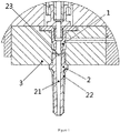
- the bioprinter spray head assembly comprises a spray head 1 and an extension rod 2 spaced from the spray head 1 and disposed adjacent to an outlet of the spray head 1, wherein an elongated flow channel 21 is provided in the extension rod 2 to guide a fluid printing unit serving as a biological printing material in the flow channel 21 to be orientedly sprayed.
- the extension rod 2 having a flow channel 21 may be disposed at a position adjacent to the outlet of the spray head 1 by means of a mounting block 3, and the fluid printing unit serving as a biological printing material is guided by the flow channel 21 such as to be orientedly sprayed.
- the fluid printing unit is subjected to a more uniform pressure in the draining and spraying process, and easily maintains a favorable flow ability.
- the flow direction of the biological printing material is more stable, which relieves the condition of mutual crowd and compression between the fluid printing units, and reduces the damage of the fluid printing unit by the mechanical force in the printing process.
- the fluid printing unit refers to a printing unit of a biological printing material, which may be a unit composed of a single first material (for example bio-ink), and may also be a unit of mixed fluids consisting of a first material wrapped with a second material (for example hydrogel).
- the extension rod 2 may also spray a strip-like continuous or non-continuous substance mixed with a fluid printing unit.
- the fluid printing unit may also be an elongated mixture, the overall structure of which is similar to sandwich noodles.
- the flow channel 21 can perform an oriented sequence of the fluid printing unit, so as to reduce the possibility of clogging.
- the flow channel 21 also facilitates the second material to uniformly wrap and protect the first material.
- the flow channel 21 which presents an elongated shape can prevent the damage produced by the friction between the biological printing material and the metal material in the printing process, the flow channel 21 can protect the fluid printing unit and reduce the influence of the damage of the fluid printing unit by the mechanical force in the printing process.
- the flow channel 21 may be straight as shown in the drawing so that the fluid printing unit is sprayed downwards, and may also be arranged in a curved structural form according to the printing requirements, so as to provide more options in the spray direction.
- a thermal insulation member 22 may also be provided on the outer periphery of the extension rod 2.
- the thermal insulation member 22 can ensure that the fluid printing unit keeps a desired temperature in the flow channel 21 and maintains the activity of the fluid printing unit.
- the thermal insulation member 22 is disposed lateral to a flow path of the fluid printing unit, and the thermal insulation member 22 is wrapped at a periphery along a movement path of the fluid printing unit, so as to achieve thermal insulation.
- such structural form overcomes the technical drawback that the spray head has to project certain length so as to facilitate applying a sprayed material in the case without an extension rod while thermal insulation is not available.
- the flow channel 21 is tapered from its inlet to outlet.
- the flow channel 21 is designed such that the fluid printing unit travels in the flow channel 21 to facilitate raising the flow rate of the fluid printing unit at the outlet of the flow channel 21 and reduce the possibility of its clogging.
- the cross section of the flow channel 21 taken along the flow direction of the fluid printing unit is conical.
- the conical flow channel 21 in a structural form similar to a funnel or a subway gate makes a more uniform distribution of the fluid printing unit in the flow channel 21, and further reduces the possibility of its clogging.
- the conical flow channel which is easy to process, presents a favorable implementability.
- the inlet of the flow channel 21 is sized to be 2 times the size of the fluid printing unit so that the inlet of the flow channel 21 is only accessible for two fluid printing units side by side at most. Since the flow channel 21 is a tapered flow channel, it is only possible to flow out a single row of fluid printing units reaching the outlet of the flow channel 21, such as to enable further reducing the possibility of the clogging of the fluid printing unit, and facilitating the spray of the fluid printing units in a single row.
- the inlet of the flow channel 21 described in the present embodiment may be a circular hole channel, and thus the fluid printing unit recited in the present embodiment may be in the shape of a sphere.
- the size of the inlet of the flow channel 21 recited in the present embodiment is the diameter at the inlet of the flow channel 21, and the size of the fluid printing unit is the diameter of the fluid printing unit.
- the outlet of the flow channel 21 is sized to be 1-1.5 times, preferably 1.2 times the size of the fluid printing unit.
- the flow channel 21 not only facilitates the spray of the fluid printing units in a single row, but also can avoid that the second material wraps the first material in an excessive thickness in the case of ensuring that the first material is not damaged, and facilitate further raising the flow rate of the fluid printing unit at the outlet of the flow channel, and ensuring the continuity and uniformity of the spray of the fluid printing unit in a single row.
- an open recess 23 is provided on an end surface of the extension rod 2 adjacent to the spray head 1.
- An outlet of the open recess 23 communicates with the flow channel 21, and the spray head 1 extends into the open recess 23.
- the cross section of the open recess 23 is tapered toward the flow channel 21, and a second material flow channel is formed between an outer wall of the spray head 1 and the open recess 23, forming a chamber between the outlet of the spray head 1 and the outlet of the open recess 23.
- the second material passing through the second material flow channel wraps a first material sprayed from the outlet of the spray head 1 in the chamber, so as to form a fluid printing unit.
- a second material flow channel is formed between an outer wall of the spray head 1 and the open recess 23, and a chamber is formed between the outlet of the spray head 1 and the outlet of the open recess 23.
- the second material passes through the second material flow channel to enter the chamber and wraps the first material sprayed from the spray head, so as to form a mixed fluid printing unit.
- the first material is a printing material containing cells (for example bio-ink), and the second material is a printing material that does not contain cells.
- the second material is a material with temperature-sensitive properties, especially a biocompatible material with temperature-sensitive properties and certain viscosity (for example hydrogels).
- the first material is a printing material that does not contain cells
- the second material is a printing material that contains cells.
- the first material and the second material may also be printing materials that both contain cells, or may also be printing materials that do not contain cells.
- first material and the second material are one of the following several morphologies: homogeneous, non-homogeneous (e.g., granular mixture), continuous or discontinuous fluid.
- the second material flow channel since a second material flow channel is formed between the outer wall of the spray head 1 and the tapered open recess 23, the second material flow channel has the function of a uniform pressure. Even if the second material enters the second material flow channel from one side as shown in Figure 1 , it still presents a uniform pressure intensity within the second material flow channel, thereby ensuring that the biological material presents a uniform wrapping effect at one side adjacent to or far from the second material inlet.
- the section of the open recess 23 taken along the flow direction of the fluid printing unit is preferably conical, and the open recess 23 presenting a conical structure allows the second material to flow along a conical face of the open recess 23, which produces the effect of converging towards the outlet of the spray head 1, and facilitates the uniform wrapping of the first material unit by the second material unit.
- the open recess 23 of the structural form can also ensure a more stable flow direction within the chamber.
- the mixed fluid printing unit flows within the open recess 23, and the open recess 23 facilitates the convergence of the fluid printing unit toward the flow channel 21 of the extension rod 2, so as to ensure that the flow direction of the mixed fluid printing unit within the chamber is more stable, and avoid its diffusion in the second material flow channel.
- the gap between the outlet of the spray head 1 and the open recess 23 is smaller than the size of the fluid printing unit, which can prevent the fluid printing unit from reversely flowing toward the second material flow channel, and ensure that the fluid printing unit within the chamber flows stably to the flow channel 21.
- the process of wrapping the first material with the second material is as follows:
- the second material enters the chamber through the second material flow channel formed between the outer wall of the spray head 1 and the open recess 23.
- the second material in the chamber has certain pressure, and the second material is compressed such as to be adhered to a portion of the first material unit projecting from the spray head 1. Until the entire first material unit is sprayed, the second material completely wraps the first material unit, to form a mixed fluid printing unit.
- the first material unit enters the flow channel 21 of the extension rod 2 under the continuous wrapping of the second material, and the first material unit surrounded by the second material orientedly flows within the flow channel 21, and is uniformly wrapped, and sequentially sprayed.
- the first material is adequately and uniformly wrapped by the second material, and the second material which is wrapped around the first material to form a protective structure before the first material is sprayed from the outlet of the flow channel 21, further reduces the influence of the printing process over the first material.
- the present disclosure further provides a bioprinter, which comprises the aforementioned bioprinter spray head assembly.
- a bioprinter spray head assembly of the present disclosure can prevent clogging of the biological printing material
- the bioprinter according to the present disclosure also correspondingly has the advantageous technical effects described above.
- the bioprinter is a 3D bioprinter
- the bioprinter spray head assembly of the present disclosure is especially suitable for a 3D bioprinter.
- extension rod 2 may be integrated with the spray head 1 without needing to provide the mounting block 3.
- multiple changes, modifications, equivalent replacements, and variations made to such embodiments still fall within the protection scope of the present disclosure.
Landscapes
- Engineering & Computer Science (AREA)
- Chemical & Material Sciences (AREA)
- Materials Engineering (AREA)
- Health & Medical Sciences (AREA)
- Manufacturing & Machinery (AREA)
- Optics & Photonics (AREA)
- Mechanical Engineering (AREA)
- Physics & Mathematics (AREA)
- Biomedical Technology (AREA)
- Heart & Thoracic Surgery (AREA)
- General Health & Medical Sciences (AREA)
- Public Health (AREA)
- Veterinary Medicine (AREA)
- Life Sciences & Earth Sciences (AREA)
- Vascular Medicine (AREA)
- Animal Behavior & Ethology (AREA)
- Transplantation (AREA)
- Oral & Maxillofacial Surgery (AREA)
- Cardiology (AREA)
- Apparatus Associated With Microorganisms And Enzymes (AREA)
- Coating Apparatus (AREA)
- Prostheses (AREA)
- Nozzles (AREA)
Claims (13)
- Biodrucker-Sprühkopfanordnung, einen Sprühkopf (1) und einen Verlängerungsstab (2) umfassend, der von dem Sprühkopf (1) beabstandet und angrenzend an einen Auslass des Sprühkopfes (1) angeordnet ist, wobei in dem Verlängerungsstab (2) ein länglicher Strömungskanal (21) vorgesehen ist, um eine Fluiddruckeinheit, die als ein biologisches Druckmaterial dient, welche ausgerichtet zu sprühen ist, in dem Strömungskanal (21) zu führen, dadurch gekennzeichnet, dass an einer Endseite des Verlängerungsstabes (2), angrenzend an den Sprühkopf (1), eine offene Vertiefung (23) bereitgestellt ist, wobei ein Auslass der offenen Vertiefung (23) mit dem Strömungskanal (21) in Verbindung steht, wobei sich der Sprühkopf (1) in die offene Vertiefung (23) erstreckt, die sich hin zum Strömungskanal (21) verjüngt, wobei zwischen einer Außenwand des Sprühkopfes (1) und der offenen Vertiefung (23) ein zweiter Materialströmungskanal gebildet ist, wobei zwischen dem Auslass des Sprühkopfes (1) und dem Auslass der offenen Vertiefung (23) eine Kammer gebildet ist, so dass ein zweites Material, das durch den zweiten Materialströmungskanal strömt, ein erstes Material umhüllt, das aus dem Auslass des Sprühkopfes (1) in die Kammer gesprüht wird, um so die Fluiddruckeinheit zu bilden.
- Biodrucker-Sprühkopfanordnung nach Anspruch 1, wobei der Strömungskanal (21) sich von seinem Einlass zu seinem Auslass verjüngt.
- Biodrucker-Sprühkopfanordnung nach Anspruch 2, wobei der Strömungskanal (21) einen konischen Querschnitt, entlang einer Strömungsrichtung der Fluiddruckeinheit genommen, aufweist.
- Biodrucker-Sprühkopfanordnung nach Anspruch 2, wobei der Auslass des Strömungskanals (21) derart bemessen ist, dass er die 1- bis 1,5-fache Größe der Fluiddruckeinheit aufweist.
- Biodrucker-Sprühkopfanordnung nach Anspruch 4, wobei der Auslass des Strömungskanals (21) derart bemessen ist, dass er die 1,2-fache Größe der Fluiddruckeinheit aufweist.
- Biodrucker-Sprühkopfanordnung nach Anspruch 2, wobei der Einlass des Strömungskanals (21) derart bemessen ist, dass er die 2- bis 5-fache Größe der Fluiddruckeinheit aufweist.
- Biodrucker-Sprühkopfanordnung nach Anspruch 6, wobei der Einlass des Strömungskanals (21) derart bemessen ist, dass er die 2-fache Größe der Fluiddruckeinheit aufweist.
- Biodrucker-Sprühkopfanordnung nach Anspruch 1, wobei ein Spalt zwischen dem Auslass des Sprühkopfes (1) und der offenen Vertiefung (23) kleiner als die Größe der Fluiddruckeinheit ist.
- Biodrucker-Sprühkopfanordnung nach Anspruch 1, wobei die offene Vertiefung (23) einen konischen Querschnitt, entlang einer Strömungsrichtung der Fluiddruckeinheit genommen, aufweist.
- Biodrucker-Sprühkopfanordnung nach Anspruch 1, ferner ein Wärmeisolationselement (22) an einem Außenumfang des Verlängerungsstabes (2) umfassend.
- Biodrucker-Sprühkopfanordnung nach Anspruch 1, wobei der Strömungskanal (21) gerade oder gekrümmt ist.
- Biodrucker, die Biodrucker-Sprühkopfanordnung nach Anspruch 1 umfassend.
- Biodrucker nach Anspruch 12, wobei der Biodrucker ein 3D-Biodrucker ist.
Applications Claiming Priority (1)
| Application Number | Priority Date | Filing Date | Title |
|---|---|---|---|
| PCT/CN2015/099855 WO2017113186A1 (zh) | 2015-12-30 | 2015-12-30 | 生物打印机喷头组件及生物打印机 |
Publications (3)
| Publication Number | Publication Date |
|---|---|
| EP3398779A1 EP3398779A1 (de) | 2018-11-07 |
| EP3398779A4 EP3398779A4 (de) | 2019-07-31 |
| EP3398779B1 true EP3398779B1 (de) | 2020-08-26 |
Family
ID=59224060
Family Applications (1)
| Application Number | Title | Priority Date | Filing Date |
|---|---|---|---|
| EP15911815.7A Active EP3398779B1 (de) | 2015-12-30 | 2015-12-30 | Düsenanordnung für biologischen drucker sowie biologischer drucker |
Country Status (4)
| Country | Link |
|---|---|
| US (1) | US10744715B2 (de) |
| EP (1) | EP3398779B1 (de) |
| JP (1) | JP6781260B2 (de) |
| WO (1) | WO2017113186A1 (de) |
Families Citing this family (3)
| Publication number | Priority date | Publication date | Assignee | Title |
|---|---|---|---|---|
| CN109968667B (zh) * | 2019-03-05 | 2021-05-11 | 苏州知云创宇信息科技有限公司 | 一种生物打印机用的喷头组件 |
| CN110253881B (zh) * | 2019-06-26 | 2021-05-28 | 太原理工大学 | 一种多喷头3d生物打印装置及打印方法 |
| CN113524675A (zh) * | 2020-04-14 | 2021-10-22 | 昆山博力迈三维打印科技有限公司 | 一种多流道3d打印机喷头 |
Family Cites Families (13)
| Publication number | Priority date | Publication date | Assignee | Title |
|---|---|---|---|---|
| JPS57120482A (en) | 1981-01-20 | 1982-07-27 | Matsushita Electric Ind Co Ltd | Fluid supplying element |
| US5074443A (en) * | 1989-12-20 | 1991-12-24 | Nordson Corporation | Adaptor for liquid dispensing syringe |
| US6267266B1 (en) | 1995-11-16 | 2001-07-31 | Nordson Corporation | Non-contact liquid material dispenser having a bellows valve assembly and method for ejecting liquid material onto a substrate |
| TW200500160A (en) * | 2003-03-28 | 2005-01-01 | Japan Science & Tech Agency | Device and method of injecting metal |
| US7938341B2 (en) | 2004-12-13 | 2011-05-10 | Optomec Design Company | Miniature aerosol jet and aerosol jet array |
| US10119107B2 (en) | 2013-05-30 | 2018-11-06 | The University Of Akron | Automated cell and tissue bioprinter |
| CN203665960U (zh) * | 2013-07-26 | 2014-06-25 | 周文 | 一种防堵塞的3d打印机打印头 |
| CN104742366B (zh) | 2013-12-31 | 2018-06-22 | 王盘龙 | 一种3d打印机喷头装置 |
| CN203994731U (zh) | 2014-08-19 | 2014-12-10 | 深圳森工科技有限公司 | 3d打印机的打印头喷头组件 |
| CN204382664U (zh) | 2014-10-23 | 2015-06-10 | 成都金采科技有限公司 | 一种3d打印喷头 |
| CN104441654B (zh) | 2014-10-27 | 2016-08-24 | 清华大学深圳研究生院 | 一种三维生物打印装置及方法 |
| CN105167879B (zh) * | 2015-06-25 | 2017-08-22 | 南京律动生物科技有限公司 | 一种双流道喷嘴 |
| CN204894532U (zh) * | 2015-08-14 | 2015-12-23 | 深圳市优特打印耗材有限公司 | 一种防堵型3d打印机喷嘴结构 |
-
2015
- 2015-12-30 WO PCT/CN2015/099855 patent/WO2017113186A1/zh active Application Filing
- 2015-12-30 US US16/067,566 patent/US10744715B2/en active Active
- 2015-12-30 EP EP15911815.7A patent/EP3398779B1/de active Active
- 2015-12-30 JP JP2018534119A patent/JP6781260B2/ja active Active
Non-Patent Citations (1)
| Title |
|---|
| None * |
Also Published As
| Publication number | Publication date |
|---|---|
| EP3398779A1 (de) | 2018-11-07 |
| JP2019503289A (ja) | 2019-02-07 |
| JP6781260B2 (ja) | 2020-11-04 |
| EP3398779A4 (de) | 2019-07-31 |
| US20190009467A1 (en) | 2019-01-10 |
| US10744715B2 (en) | 2020-08-18 |
| WO2017113186A1 (zh) | 2017-07-06 |
Similar Documents
| Publication | Publication Date | Title |
|---|---|---|
| EP3398779B1 (de) | Düsenanordnung für biologischen drucker sowie biologischer drucker | |
| EP3056284B1 (de) | Klebstoffabgabemodul und verfahren zum sprühen einer vielzahl von tropfen eines flüssigklebstoffs | |
| EP3398777B1 (de) | Biodruckerdüsenanordnung und biodrucker | |
| US11465346B2 (en) | Bioprinter spray head assembly and bioprinter | |
| EP2163314A3 (de) | Flüssigmaterialspender | |
| RU2012112219A (ru) | Дозирующее устройство и способ дозирования продукта | |
| CA2640881A1 (en) | Drug delivery device and method | |
| EP2536635A4 (de) | Direktfüllungs-trockenpulversysteme mit für ein- und ausschaltbaren durchfluss konfigurierten dosierungsköpfen | |
| DE14853999T1 (de) | Verwirbelungsdüse mit steuerbarer geschwindigkeit | |
| MY192610A (en) | Discharge device and discharge method for liquid material containing solid particles, and coating device | |
| JP2009262946A (ja) | 定量注出容器 | |
| WO2013052734A3 (en) | Direct dispense device and method | |
| KR102228891B1 (ko) | 도징 시스템, 도징 방법, 및 제조 방법 | |
| US8640641B2 (en) | Multi-slot applicator with automatic closing function | |
| US9567117B2 (en) | Device and method for filling a container | |
| WO2011117730A3 (en) | Liquid dispensing system for use in the formation of a tobacco pouch product | |
| JP2017509482A5 (de) | ||
| US10828830B2 (en) | Bioprinter | |
| CN105670918B (zh) | 生物打印机喷头组件及生物打印机 | |
| DE102014117390B3 (de) | Vorrichtung zum Ausbringen eines flüssigen Mediums in Tropfenform | |
| RU2015134331A (ru) | Управляющее устройство и устройство выдачи | |
| CN205313573U (zh) | 生物打印机喷头组件及生物打印机 | |
| RU39049U1 (ru) | Контейнер для хранения и выдачи препарата (варианты) | |
| JP2001068092A (ja) | 間欠的に高速注液するのに適した注液ノズル | |
| PL239020B1 (pl) | Aplikator cieczy |
Legal Events
| Date | Code | Title | Description |
|---|---|---|---|
| STAA | Information on the status of an ep patent application or granted ep patent |
Free format text: STATUS: THE INTERNATIONAL PUBLICATION HAS BEEN MADE |
|
| PUAI | Public reference made under article 153(3) epc to a published international application that has entered the european phase |
Free format text: ORIGINAL CODE: 0009012 |
|
| STAA | Information on the status of an ep patent application or granted ep patent |
Free format text: STATUS: REQUEST FOR EXAMINATION WAS MADE |
|
| 17P | Request for examination filed |
Effective date: 20180726 |
|
| AK | Designated contracting states |
Kind code of ref document: A1 Designated state(s): AL AT BE BG CH CY CZ DE DK EE ES FI FR GB GR HR HU IE IS IT LI LT LU LV MC MK MT NL NO PL PT RO RS SE SI SK SM TR |
|
| AX | Request for extension of the european patent |
Extension state: BA ME |
|
| DAV | Request for validation of the european patent (deleted) | ||
| DAX | Request for extension of the european patent (deleted) | ||
| A4 | Supplementary search report drawn up and despatched |
Effective date: 20190703 |
|
| RIC1 | Information provided on ipc code assigned before grant |
Ipc: B05B 7/00 20060101ALI20190627BHEP Ipc: B41J 2/14 20060101ALN20190627BHEP Ipc: A61F 2/30 20060101ALN20190627BHEP Ipc: B33Y 40/00 20150101ALI20190627BHEP Ipc: B29C 64/209 20170101AFI20190627BHEP Ipc: B05B 7/04 20060101ALI20190627BHEP Ipc: B33Y 30/00 20150101ALI20190627BHEP Ipc: A61F 2/02 20060101ALI20190627BHEP |
|
| RIC1 | Information provided on ipc code assigned before grant |
Ipc: B33Y 40/00 20200101ALI20200205BHEP Ipc: B33Y 30/00 20150101ALI20200205BHEP Ipc: B41J 2/14 20060101ALN20200205BHEP Ipc: B05B 7/00 20060101ALI20200205BHEP Ipc: A61F 2/30 20060101ALN20200205BHEP Ipc: B29C 64/209 20170101AFI20200205BHEP Ipc: B05B 7/04 20060101ALI20200205BHEP Ipc: A61F 2/02 20060101ALI20200205BHEP |
|
| GRAP | Despatch of communication of intention to grant a patent |
Free format text: ORIGINAL CODE: EPIDOSNIGR1 |
|
| STAA | Information on the status of an ep patent application or granted ep patent |
Free format text: STATUS: GRANT OF PATENT IS INTENDED |
|
| RIC1 | Information provided on ipc code assigned before grant |
Ipc: B05B 7/00 20060101ALI20200305BHEP Ipc: B05B 7/04 20060101ALI20200305BHEP Ipc: B41J 2/14 20060101ALN20200305BHEP Ipc: B33Y 40/00 20200101ALI20200305BHEP Ipc: A61F 2/30 20060101ALN20200305BHEP Ipc: B33Y 30/00 20150101ALI20200305BHEP Ipc: B29C 64/209 20170101AFI20200305BHEP Ipc: A61F 2/02 20060101ALI20200305BHEP |
|
| INTG | Intention to grant announced |
Effective date: 20200317 |
|
| GRAJ | Information related to disapproval of communication of intention to grant by the applicant or resumption of examination proceedings by the epo deleted |
Free format text: ORIGINAL CODE: EPIDOSDIGR1 |
|
| STAA | Information on the status of an ep patent application or granted ep patent |
Free format text: STATUS: REQUEST FOR EXAMINATION WAS MADE |
|
| REG | Reference to a national code |
Ref country code: DE Ref legal event code: R079 Ref document number: 602015058213 Country of ref document: DE Free format text: PREVIOUS MAIN CLASS: B33Y0030000000 Ipc: B29C0064209000 |
|
| INTC | Intention to grant announced (deleted) | ||
| GRAR | Information related to intention to grant a patent recorded |
Free format text: ORIGINAL CODE: EPIDOSNIGR71 |
|
| GRAS | Grant fee paid |
Free format text: ORIGINAL CODE: EPIDOSNIGR3 |
|
| STAA | Information on the status of an ep patent application or granted ep patent |
Free format text: STATUS: GRANT OF PATENT IS INTENDED |
|
| GRAA | (expected) grant |
Free format text: ORIGINAL CODE: 0009210 |
|
| STAA | Information on the status of an ep patent application or granted ep patent |
Free format text: STATUS: THE PATENT HAS BEEN GRANTED |
|
| RIC1 | Information provided on ipc code assigned before grant |
Ipc: B41J 2/14 20060101ALN20200629BHEP Ipc: B05B 7/04 20060101ALI20200629BHEP Ipc: B33Y 40/00 20200101ALI20200629BHEP Ipc: B05B 7/00 20060101ALI20200629BHEP Ipc: B33Y 30/00 20150101ALI20200629BHEP Ipc: A61F 2/02 20060101ALI20200629BHEP Ipc: B29C 64/209 20170101AFI20200629BHEP Ipc: A61F 2/30 20060101ALN20200629BHEP |
|
| AK | Designated contracting states |
Kind code of ref document: B1 Designated state(s): AL AT BE BG CH CY CZ DE DK EE ES FI FR GB GR HR HU IE IS IT LI LT LU LV MC MK MT NL NO PL PT RO RS SE SI SK SM TR |
|
| INTG | Intention to grant announced |
Effective date: 20200721 |
|
| REG | Reference to a national code |
Ref country code: GB Ref legal event code: FG4D |
|
| REG | Reference to a national code |
Ref country code: CH Ref legal event code: EP |
|
| REG | Reference to a national code |
Ref country code: AT Ref legal event code: REF Ref document number: 1305960 Country of ref document: AT Kind code of ref document: T Effective date: 20200915 |
|
| REG | Reference to a national code |
Ref country code: DE Ref legal event code: R082 Ref document number: 602015058213 Country of ref document: DE Representative=s name: LAVOIX MUNICH, DE Ref country code: IE Ref legal event code: FG4D |
|
| REG | Reference to a national code |
Ref country code: DE Ref legal event code: R096 Ref document number: 602015058213 Country of ref document: DE |
|
| REG | Reference to a national code |
Ref country code: CH Ref legal event code: NV Representative=s name: MICHELI AND CIE SA, CH |
|
| REG | Reference to a national code |
Ref country code: SE Ref legal event code: TRGR |
|
| REG | Reference to a national code |
Ref country code: FI Ref legal event code: FGE |
|
| REG | Reference to a national code |
Ref country code: NL Ref legal event code: FP |
|
| REG | Reference to a national code |
Ref country code: LT Ref legal event code: MG4D |
|
| PG25 | Lapsed in a contracting state [announced via postgrant information from national office to epo] |
Ref country code: BG Free format text: LAPSE BECAUSE OF FAILURE TO SUBMIT A TRANSLATION OF THE DESCRIPTION OR TO PAY THE FEE WITHIN THE PRESCRIBED TIME-LIMIT Effective date: 20201126 Ref country code: HR Free format text: LAPSE BECAUSE OF FAILURE TO SUBMIT A TRANSLATION OF THE DESCRIPTION OR TO PAY THE FEE WITHIN THE PRESCRIBED TIME-LIMIT Effective date: 20200826 Ref country code: PT Free format text: LAPSE BECAUSE OF FAILURE TO SUBMIT A TRANSLATION OF THE DESCRIPTION OR TO PAY THE FEE WITHIN THE PRESCRIBED TIME-LIMIT Effective date: 20201228 Ref country code: LT Free format text: LAPSE BECAUSE OF FAILURE TO SUBMIT A TRANSLATION OF THE DESCRIPTION OR TO PAY THE FEE WITHIN THE PRESCRIBED TIME-LIMIT Effective date: 20200826 Ref country code: GR Free format text: LAPSE BECAUSE OF FAILURE TO SUBMIT A TRANSLATION OF THE DESCRIPTION OR TO PAY THE FEE WITHIN THE PRESCRIBED TIME-LIMIT Effective date: 20201127 Ref country code: NO Free format text: LAPSE BECAUSE OF FAILURE TO SUBMIT A TRANSLATION OF THE DESCRIPTION OR TO PAY THE FEE WITHIN THE PRESCRIBED TIME-LIMIT Effective date: 20201126 |
|
| REG | Reference to a national code |
Ref country code: AT Ref legal event code: MK05 Ref document number: 1305960 Country of ref document: AT Kind code of ref document: T Effective date: 20200826 |
|
| PG25 | Lapsed in a contracting state [announced via postgrant information from national office to epo] |
Ref country code: PL Free format text: LAPSE BECAUSE OF FAILURE TO SUBMIT A TRANSLATION OF THE DESCRIPTION OR TO PAY THE FEE WITHIN THE PRESCRIBED TIME-LIMIT Effective date: 20200826 Ref country code: RS Free format text: LAPSE BECAUSE OF FAILURE TO SUBMIT A TRANSLATION OF THE DESCRIPTION OR TO PAY THE FEE WITHIN THE PRESCRIBED TIME-LIMIT Effective date: 20200826 Ref country code: LV Free format text: LAPSE BECAUSE OF FAILURE TO SUBMIT A TRANSLATION OF THE DESCRIPTION OR TO PAY THE FEE WITHIN THE PRESCRIBED TIME-LIMIT Effective date: 20200826 Ref country code: IS Free format text: LAPSE BECAUSE OF FAILURE TO SUBMIT A TRANSLATION OF THE DESCRIPTION OR TO PAY THE FEE WITHIN THE PRESCRIBED TIME-LIMIT Effective date: 20201226 |
|
| PG25 | Lapsed in a contracting state [announced via postgrant information from national office to epo] |
Ref country code: DK Free format text: LAPSE BECAUSE OF FAILURE TO SUBMIT A TRANSLATION OF THE DESCRIPTION OR TO PAY THE FEE WITHIN THE PRESCRIBED TIME-LIMIT Effective date: 20200826 Ref country code: CZ Free format text: LAPSE BECAUSE OF FAILURE TO SUBMIT A TRANSLATION OF THE DESCRIPTION OR TO PAY THE FEE WITHIN THE PRESCRIBED TIME-LIMIT Effective date: 20200826 Ref country code: RO Free format text: LAPSE BECAUSE OF FAILURE TO SUBMIT A TRANSLATION OF THE DESCRIPTION OR TO PAY THE FEE WITHIN THE PRESCRIBED TIME-LIMIT Effective date: 20200826 Ref country code: SM Free format text: LAPSE BECAUSE OF FAILURE TO SUBMIT A TRANSLATION OF THE DESCRIPTION OR TO PAY THE FEE WITHIN THE PRESCRIBED TIME-LIMIT Effective date: 20200826 Ref country code: EE Free format text: LAPSE BECAUSE OF FAILURE TO SUBMIT A TRANSLATION OF THE DESCRIPTION OR TO PAY THE FEE WITHIN THE PRESCRIBED TIME-LIMIT Effective date: 20200826 |
|
| REG | Reference to a national code |
Ref country code: DE Ref legal event code: R097 Ref document number: 602015058213 Country of ref document: DE |
|
| PG25 | Lapsed in a contracting state [announced via postgrant information from national office to epo] |
Ref country code: AL Free format text: LAPSE BECAUSE OF FAILURE TO SUBMIT A TRANSLATION OF THE DESCRIPTION OR TO PAY THE FEE WITHIN THE PRESCRIBED TIME-LIMIT Effective date: 20200826 Ref country code: AT Free format text: LAPSE BECAUSE OF FAILURE TO SUBMIT A TRANSLATION OF THE DESCRIPTION OR TO PAY THE FEE WITHIN THE PRESCRIBED TIME-LIMIT Effective date: 20200826 Ref country code: ES Free format text: LAPSE BECAUSE OF FAILURE TO SUBMIT A TRANSLATION OF THE DESCRIPTION OR TO PAY THE FEE WITHIN THE PRESCRIBED TIME-LIMIT Effective date: 20200826 |
|
| PG25 | Lapsed in a contracting state [announced via postgrant information from national office to epo] |
Ref country code: SK Free format text: LAPSE BECAUSE OF FAILURE TO SUBMIT A TRANSLATION OF THE DESCRIPTION OR TO PAY THE FEE WITHIN THE PRESCRIBED TIME-LIMIT Effective date: 20200826 |
|
| PLBE | No opposition filed within time limit |
Free format text: ORIGINAL CODE: 0009261 |
|
| STAA | Information on the status of an ep patent application or granted ep patent |
Free format text: STATUS: NO OPPOSITION FILED WITHIN TIME LIMIT |
|
| 26N | No opposition filed |
Effective date: 20210527 |
|
| PG25 | Lapsed in a contracting state [announced via postgrant information from national office to epo] |
Ref country code: SI Free format text: LAPSE BECAUSE OF FAILURE TO SUBMIT A TRANSLATION OF THE DESCRIPTION OR TO PAY THE FEE WITHIN THE PRESCRIBED TIME-LIMIT Effective date: 20200826 Ref country code: MC Free format text: LAPSE BECAUSE OF FAILURE TO SUBMIT A TRANSLATION OF THE DESCRIPTION OR TO PAY THE FEE WITHIN THE PRESCRIBED TIME-LIMIT Effective date: 20200826 |
|
| PG25 | Lapsed in a contracting state [announced via postgrant information from national office to epo] |
Ref country code: LU Free format text: LAPSE BECAUSE OF NON-PAYMENT OF DUE FEES Effective date: 20201230 |
|
| PG25 | Lapsed in a contracting state [announced via postgrant information from national office to epo] |
Ref country code: TR Free format text: LAPSE BECAUSE OF FAILURE TO SUBMIT A TRANSLATION OF THE DESCRIPTION OR TO PAY THE FEE WITHIN THE PRESCRIBED TIME-LIMIT Effective date: 20200826 Ref country code: MT Free format text: LAPSE BECAUSE OF FAILURE TO SUBMIT A TRANSLATION OF THE DESCRIPTION OR TO PAY THE FEE WITHIN THE PRESCRIBED TIME-LIMIT Effective date: 20200826 Ref country code: CY Free format text: LAPSE BECAUSE OF FAILURE TO SUBMIT A TRANSLATION OF THE DESCRIPTION OR TO PAY THE FEE WITHIN THE PRESCRIBED TIME-LIMIT Effective date: 20200826 |
|
| PG25 | Lapsed in a contracting state [announced via postgrant information from national office to epo] |
Ref country code: MK Free format text: LAPSE BECAUSE OF FAILURE TO SUBMIT A TRANSLATION OF THE DESCRIPTION OR TO PAY THE FEE WITHIN THE PRESCRIBED TIME-LIMIT Effective date: 20200826 |
|
| PGFP | Annual fee paid to national office [announced via postgrant information from national office to epo] |
Ref country code: SE Payment date: 20221110 Year of fee payment: 8 Ref country code: NL Payment date: 20221114 Year of fee payment: 8 Ref country code: IT Payment date: 20221111 Year of fee payment: 8 Ref country code: IE Payment date: 20221109 Year of fee payment: 8 Ref country code: GB Payment date: 20221110 Year of fee payment: 8 Ref country code: FR Payment date: 20221110 Year of fee payment: 8 Ref country code: FI Payment date: 20221209 Year of fee payment: 8 Ref country code: DE Payment date: 20221102 Year of fee payment: 8 |
|
| PGFP | Annual fee paid to national office [announced via postgrant information from national office to epo] |
Ref country code: BE Payment date: 20221118 Year of fee payment: 8 |
|
| PGFP | Annual fee paid to national office [announced via postgrant information from national office to epo] |
Ref country code: CH Payment date: 20230101 Year of fee payment: 8 |